Embed Size (px)
Citation preview
Study of Change in Resonance Characteristics for a Passive Bimorph
Damper
1SHANKER GANESH KRISHNAMOORTHY, 2INGA SKIEDRAITE, 3SYLVESTER SEDEM
DJOKOTO, 4EGIDIJUS DRAGASIUS, 5 RAMUNAS SKVIRECKAS
Faculty of Mechanical Engineering and Design
Kaunas University of Technology
Studentu Str. 56, Kaunas, LT–51424
LITHUANIA [email protected], [email protected], [email protected]
[email protected], [email protected]
Abstract: Piezo materials are widely used as dampers in smart systems due to their unique properties. Several
research was developed to understand the damping process strategy in piezoelectric dampers, but by giving less
consideration to the effect of directly shorting terminals between passive and active layers. This research work
aims to study the influence of shorting terminals of passive and active layers at the time of resonance. Simple
bimorph cantilever was used for the research study to illustrate the effectiveness of the proposed technique. The
experiment setup consists of input unit (wave generator amplifier, and shaker), and output unit (optical sensor,
vibrometer, picoscope, and computer). The PicoScope software was used to analyze the final result. The results
show that the new approach has a positive effect, where the amplitude of vibration at resonance can be reduced
up to 50 %.
Key-Words: Bimorph, piezoelectric damper, shunt damping, resonance damping, passive damping, active
damping.
1 Introduction Piezoelectric materials are widely used in multimodal
vibration damping [1] and resonant damping [2-6].
Unique properties of piezoelectric materials make it
easy to install, operate, and maintain it as a resonance
damper. The piezoelectric patches used for damping,
will not be sized, to actuate the structure nor
significantly change the stiffness of the structure to
which it is attached. Thus piezoelectric dampers can
be tuned to remove energy at time of resonance,
which results in reduced vibration amplitude.
Mechanical vibration can be dissipated through an
active or passive technique and also by combination
of both. The active technique consists of power
supplies and control system, where as in a passive
technique the physical characteristic of smart
materials determines the nature of damping [1].
The passive damping can be classified as
structural and embedded damping. Damping
obtained by friction of junctions, cable rubbing and
material damping are categorized as structural
damping. Embedded damping is achieved by adding
dissipation mechanism like: viscoelastic materials,
viscous devices, magnetic devices and passive
piezoelectric [1].
Existing research [1] focus on study of passive
damping systems for single mode or multiple modes,
where damping is achieved through piezoelectric
patches and resonant shunt circuits. Later this work
is followed by discussion of modelling of
piezoelectric patches coupled to shunt circuits
involving series and parallel connections. In other
research works [2-6] a combination of analytical and
experimental study was done to evaluate the
feasibility of passive and active approaches to
reduce high cycle fatigue in turbine engine fan,
compressor blades and also on other mechanical
structures.
Based on the shunt circuits the piezoelectric
dampers can be classified as [1, 2]:
1. resistive – here the system behaves similar to
viscoelastically damped systems;
2. resonant – the system is similar to classical
dynamic vibration absorber;
3. capacitive – circuit changes the stiffness of
piezoelectric element;
WSEAS TRANSACTIONS on APPLIED and THEORETICAL MECHANICS
Shanker Ganesh Krishnamoorthy, Inga Skiedraite, Sylvester Sedem Djokoto, Egidijus Dragasius, Ramunas Skvireckas
E-ISSN: 2224-3429 51 Volume 12, 2017
4. switched – there the behaviour of the circuit
in response can be adjusted with respect to
change in system.
The changes in resonance characteristics for a
bimorph cantilever setup, when the active-layer
terminals and passive-layer terminals of a bimorph
are shorted to one another without any shunt circuit
or an external power amplifier, are investigated in
this paper.
2 Electromechanical Characteristics
of Piezoelectric Damper The piezoelectric effect enables to transform a
portion of mechanical energy associated with
vibration, to electrical energy. The electrical energy
can be dissipated conveniently through a shunt circuit
[2-6].
The study of transient dynamic characteristics of
a PZT (Lead zirconate titanate) bender can be
performed using an electrical equivalent circuit.
Electrical equivalent circuit has been used in
previous research [9-10]. The voltage value obtained
for various conditions of mechanical stress were
fairly accurate. The understanding of an electrical
equivalent circuit is necessary to obtain the voltage to
strain relationship.
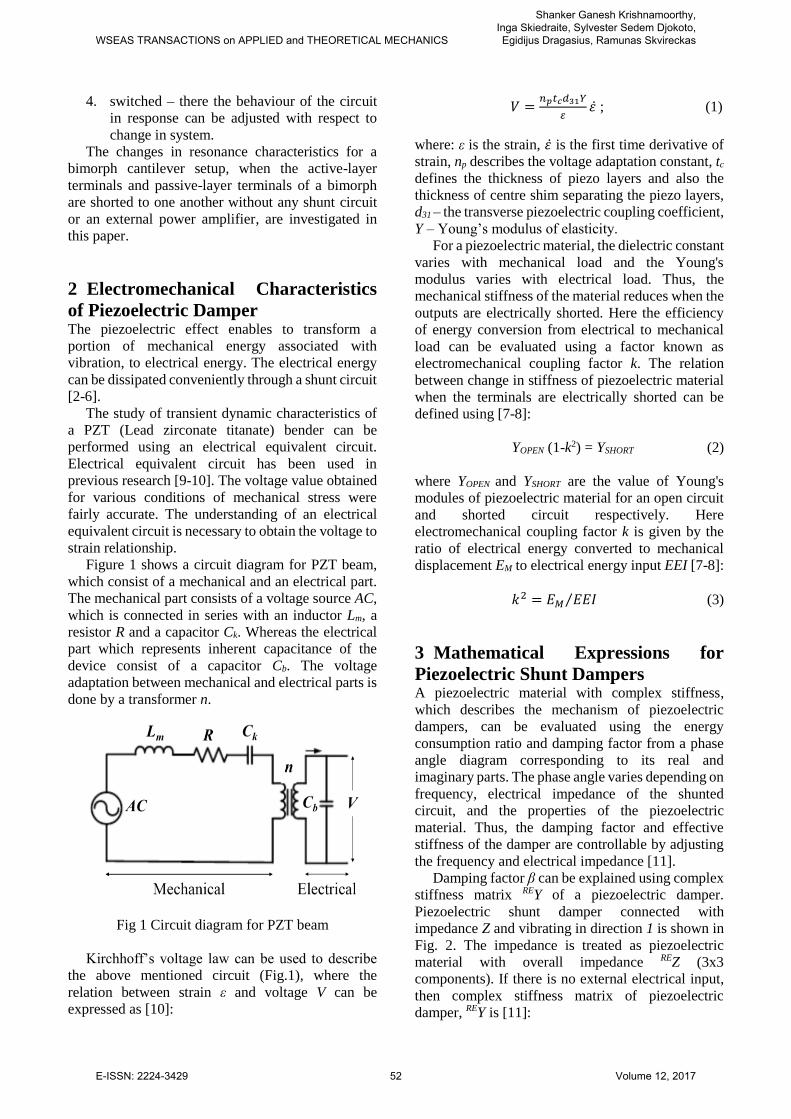
Figure 1 shows a circuit diagram for PZT beam,
which consist of a mechanical and an electrical part.
The mechanical part consists of a voltage source AC,
which is connected in series with an inductor Lm, a
resistor R and a capacitor Ck. Whereas the electrical
part which represents inherent capacitance of the
device consist of a capacitor Cb. The voltage
adaptation between mechanical and electrical parts is
done by a transformer n.
Fig 1 Circuit diagram for PZT beam
Kirchhoff’s voltage law can be used to describe
the above mentioned circuit (Fig.1), where the
relation between strain ε and voltage V can be
expressed as [10]:
𝑉 =𝑛𝑝𝑡𝑐𝑑31𝑌
𝜀𝜀̇ ; (1)
where: ε is the strain, 𝜀̇ is the first time derivative of
strain, np describes the voltage adaptation constant, tc
defines the thickness of piezo layers and also the
thickness of centre shim separating the piezo layers,
d31 – the transverse piezoelectric coupling coefficient,
Y – Young’s modulus of elasticity.
For a piezoelectric material, the dielectric constant
varies with mechanical load and the Young's
modulus varies with electrical load. Thus, the
mechanical stiffness of the material reduces when the
outputs are electrically shorted. Here the efficiency
of energy conversion from electrical to mechanical
load can be evaluated using a factor known as
electromechanical coupling factor k. The relation
between change in stiffness of piezoelectric material
when the terminals are electrically shorted can be
defined using [7-8]:
YOPEN (1-k2) = YSHORT (2)
where YOPEN and YSHORT are the value of Young's
modules of piezoelectric material for an open circuit
and shorted circuit respectively. Here
electromechanical coupling factor k is given by the
ratio of electrical energy converted to mechanical
displacement EM to electrical energy input EEI [7-8]:
𝑘2 = 𝐸𝑀 𝐸𝐸𝐼⁄ (3)
3 Mathematical Expressions for
Piezoelectric Shunt Dampers A piezoelectric material with complex stiffness,
which describes the mechanism of piezoelectric
dampers, can be evaluated using the energy
consumption ratio and damping factor from a phase
angle diagram corresponding to its real and
imaginary parts. The phase angle varies depending on
frequency, electrical impedance of the shunted
circuit, and the properties of the piezoelectric
material. Thus, the damping factor and effective
stiffness of the damper are controllable by adjusting
the frequency and electrical impedance [11].
Damping factor β can be explained using complex
stiffness matrix REY of a piezoelectric damper.
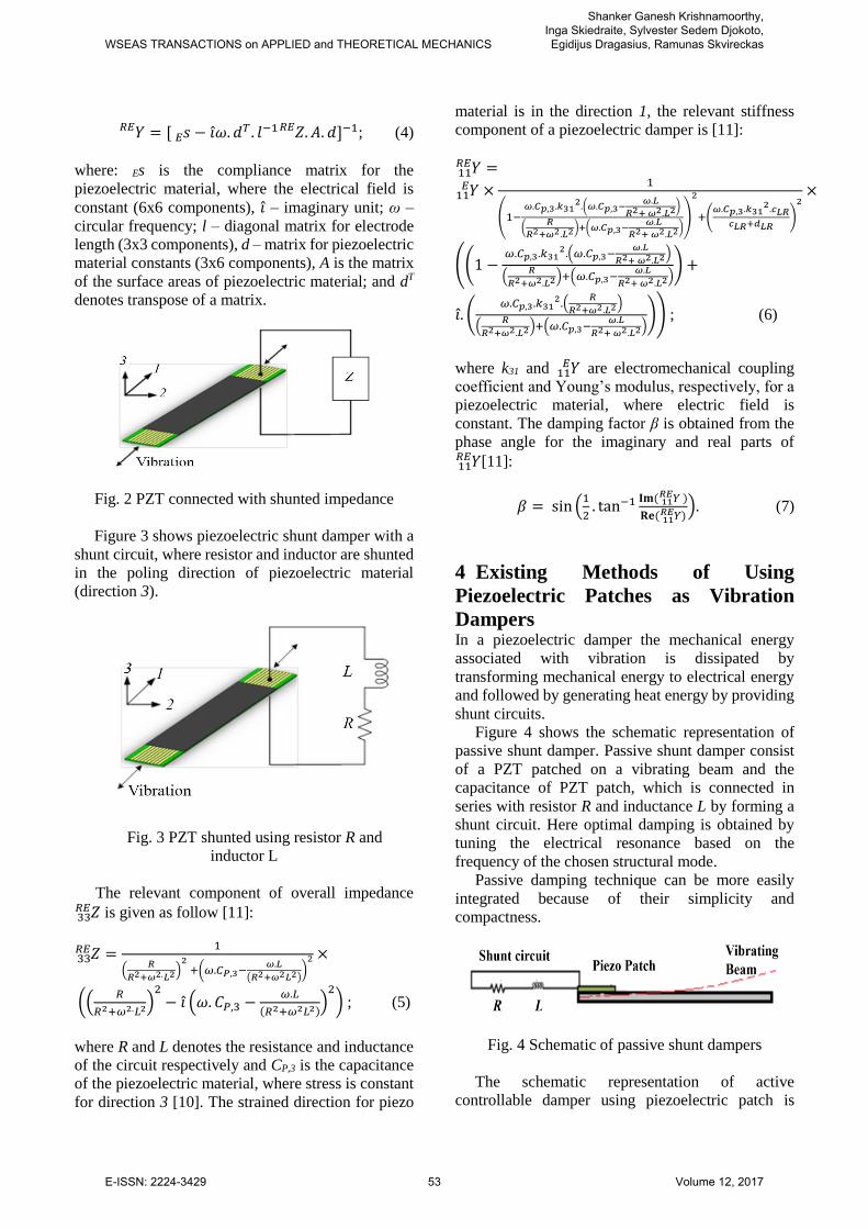
Piezoelectric shunt damper connected with
impedance Z and vibrating in direction 1 is shown in
Fig. 2. The impedance is treated as piezoelectric
material with overall impedance REZ (3x3
components). If there is no external electrical input,
then complex stiffness matrix of piezoelectric
damper, REY is [11]:
WSEAS TRANSACTIONS on APPLIED and THEORETICAL MECHANICS
Shanker Ganesh Krishnamoorthy, Inga Skiedraite, Sylvester Sedem Djokoto, Egidijus Dragasius, Ramunas Skvireckas
E-ISSN: 2224-3429 52 Volume 12, 2017
𝑌 = [ 𝑠𝐸 − 𝑖̂𝜔. 𝑑𝑇 . 𝑙−1 𝑍. 𝐴. 𝑑𝑅𝐸 ]−1𝑅𝐸 ; (4)
where: Es is the compliance matrix for the
piezoelectric material, where the electrical field is
constant (6x6 components), 𝑖 ̂– imaginary unit; ω –
circular frequency; l – diagonal matrix for electrode
length (3x3 components), d – matrix for piezoelectric
material constants (3x6 components), A is the matrix
of the surface areas of piezoelectric material; and dT
denotes transpose of a matrix.
Fig. 2 PZT connected with shunted impedance
Figure 3 shows piezoelectric shunt damper with a
shunt circuit, where resistor and inductor are shunted
in the poling direction of piezoelectric material
(direction 3).
Fig. 3 PZT shunted using resistor R and
inductor L
The relevant component of overall impedance
𝑍33𝑅𝐸 is given as follow [11]:
𝑍33𝑅𝐸 =
1
(𝑅
𝑅2+𝜔2.𝐿2)2
+(𝜔.𝐶𝑃,3−𝜔.𝐿
(𝑅2+𝜔2𝐿2))
2 ×
((𝑅
𝑅2+𝜔2.𝐿2)2
− 𝑖̂ (𝜔. 𝐶𝑃,3 −𝜔.𝐿
(𝑅2+𝜔2𝐿2))
2) ; (5)
where R and L denotes the resistance and inductance
of the circuit respectively and CP,3 is the capacitance
of the piezoelectric material, where stress is constant
for direction 3 [10]. The strained direction for piezo
material is in the direction 1, the relevant stiffness
component of a piezoelectric damper is [11]:
𝑌11𝑅𝐸 =
𝑌 ×11𝐸 1
(1−𝜔.𝐶𝑝,3.𝑘31
2.(𝜔.𝐶𝑝,3−𝜔.𝐿
𝑅2+ 𝜔2.𝐿2)
(𝑅
𝑅2+𝜔2.𝐿2)+(𝜔.𝐶𝑝,3−𝜔.𝐿
𝑅2+ 𝜔2.𝐿2))
2
+(𝜔.𝐶𝑝,3.𝑘31
2.𝑐𝐿𝑅𝑐𝐿𝑅+𝑑𝐿𝑅
)
2×
((1 −𝜔.𝐶𝑝,3.𝑘31
2.(𝜔.𝐶𝑝,3−𝜔.𝐿
𝑅2+ 𝜔2.𝐿2)
(𝑅
𝑅2+𝜔2.𝐿2)+(𝜔.𝐶𝑝,3−𝜔.𝐿
𝑅2+ 𝜔2.𝐿2)) +
𝑖.̂ (𝜔.𝐶𝑝,3.𝑘31
2.(𝑅
𝑅2+𝜔2.𝐿2)
(𝑅
𝑅2+𝜔2.𝐿2)+(𝜔.𝐶𝑝,3−𝜔.𝐿
𝑅2+ 𝜔2.𝐿2))) ; (6)
where k31 and 𝑌11𝐸 are electromechanical coupling
coefficient and Young’s modulus, respectively, for a
piezoelectric material, where electric field is
constant. The damping factor β is obtained from the
phase angle for the imaginary and real parts of
𝑌11𝑅𝐸 [11]:
𝛽 = sin (1
2. tan−1 𝐈𝐦( 𝑌11
𝑅𝐸 )
𝐑𝐞( 𝑌11𝑅𝐸 )
). (7)
4 Existing Methods of Using
Piezoelectric Patches as Vibration
Dampers In a piezoelectric damper the mechanical energy
associated with vibration is dissipated by
transforming mechanical energy to electrical energy
and followed by generating heat energy by providing
shunt circuits.
Figure 4 shows the schematic representation of
passive shunt damper. Passive shunt damper consist
of a PZT patched on a vibrating beam and the
capacitance of PZT patch, which is connected in
series with resistor R and inductance L by forming a
shunt circuit. Here optimal damping is obtained by
tuning the electrical resonance based on the
frequency of the chosen structural mode.
Passive damping technique can be more easily
integrated because of their simplicity and
compactness.
Fig. 4 Schematic of passive shunt dampers
The schematic representation of active
controllable damper using piezoelectric patch is
WSEAS TRANSACTIONS on APPLIED and THEORETICAL MECHANICS
Shanker Ganesh Krishnamoorthy, Inga Skiedraite, Sylvester Sedem Djokoto, Egidijus Dragasius, Ramunas Skvireckas
E-ISSN: 2224-3429 53 Volume 12, 2017
shown in Fig. 5. The active system consists of
piezoelectric patches in the form of sensors and
actuators, which are connected to each other through
a control system. Signals obtained from sensors are
filtered and used for communication with control
system. At a specific amplitude of vibration, the
control system will activate the actuator, thereby
providing the required damping effect for the
cantilever beam.
Fig. 5 Schematic of an active controlable damper
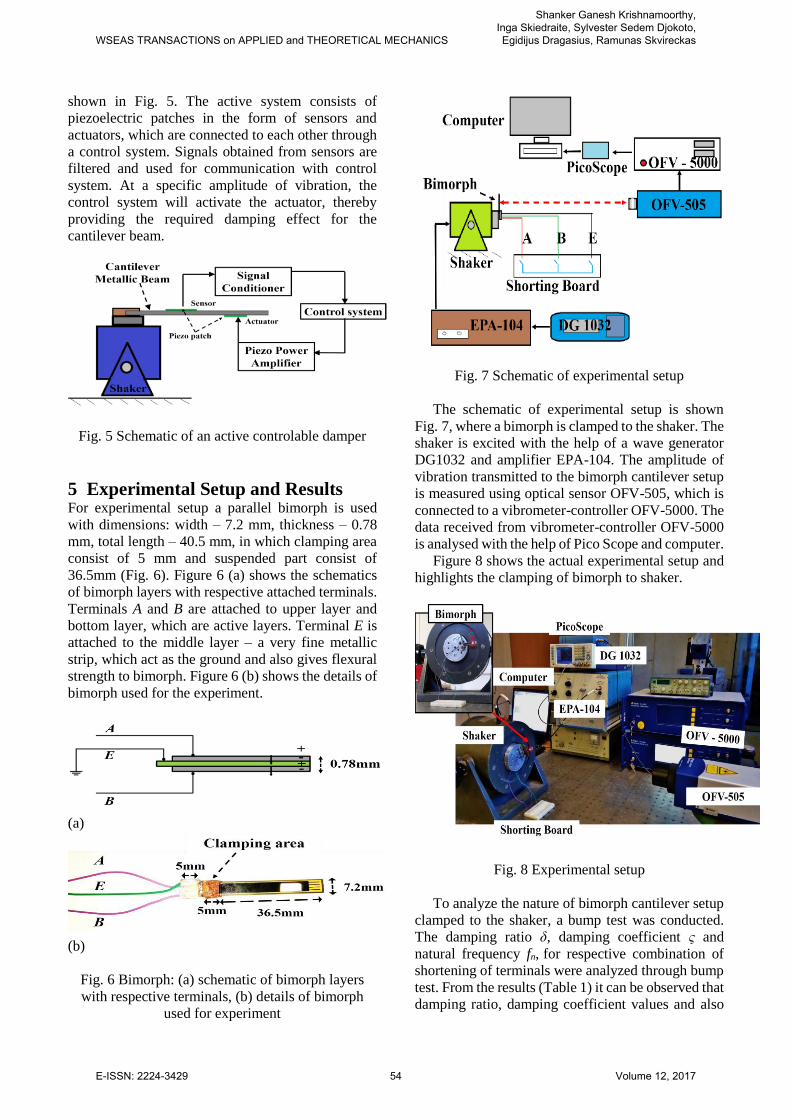
5 Experimental Setup and Results For experimental setup a parallel bimorph is used
with dimensions: width – 7.2 mm, thickness – 0.78
mm, total length – 40.5 mm, in which clamping area
consist of 5 mm and suspended part consist of
36.5mm (Fig. 6). Figure 6 (a) shows the schematics
of bimorph layers with respective attached terminals.
Terminals A and B are attached to upper layer and
bottom layer, which are active layers. Terminal E is
attached to the middle layer – a very fine metallic
strip, which act as the ground and also gives flexural
strength to bimorph. Figure 6 (b) shows the details of
bimorph used for the experiment.
(a)
(b)
Fig. 6 Bimorph: (a) schematic of bimorph layers
with respective terminals, (b) details of bimorph
used for experiment
Fig. 7 Schematic of experimental setup
The schematic of experimental setup is shown
Fig. 7, where a bimorph is clamped to the shaker. The
shaker is excited with the help of a wave generator
DG1032 and amplifier EPA-104. The amplitude of
vibration transmitted to the bimorph cantilever setup
is measured using optical sensor OFV-505, which is
connected to a vibrometer-controller OFV-5000. The
data received from vibrometer-controller OFV-5000
is analysed with the help of Pico Scope and computer.
Figure 8 shows the actual experimental setup and
highlights the clamping of bimorph to shaker.
Fig. 8 Experimental setup
To analyze the nature of bimorph cantilever setup
clamped to the shaker, a bump test was conducted.
The damping ratio δ, damping coefficient ς and
natural frequency fn, for respective combination of
shortening of terminals were analyzed through bump
test. From the results (Table 1) it can be observed that
damping ratio, damping coefficient values and also
WSEAS TRANSACTIONS on APPLIED and THEORETICAL MECHANICS
Shanker Ganesh Krishnamoorthy, Inga Skiedraite, Sylvester Sedem Djokoto, Egidijus Dragasius, Ramunas Skvireckas
E-ISSN: 2224-3429 54 Volume 12, 2017
the natural frequency varies with respect to the
terminals shorted. The results obtained can be
justified using equations (2) and (3), which describes
that the mechanical "stiffness" of the material reduces
when the output is electrically shorted.
Table 1 Results from bump test
Nature of
connection
Damping
ratio
δ
Damping
coefficient
ς
Natural
frequency
fn (Hz)
Free 0.181 0.0288 220
A+B 0.282 0.0398 221
A+E 0.123 0.0196 213.5
B+E 0.146 0.0233 213
A+B+E 0.1306 0.0208 208.5
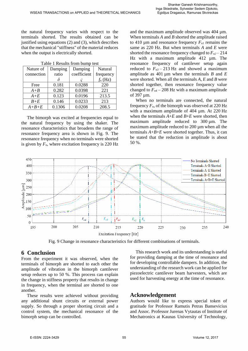
The bimorph was excited at frequencies equal to
the natural frequency by using the shaker. The
resonance characteristics that broadens the range of
resonance frequency area is shown in Fig. 9. The
resonance frequency when no terminals were shorted
is given by Fn, where excitation frequency is 220 Hz
and the maximum amplitude observed was 404 µm.
When terminals A and B shorted the amplitude raised
to 410 µm and resonance frequency Fn1 remains the
same as 220 Hz. But when terminals A and E were
shorted the resonance frequency changed to Fn2 – 214
Hz with a maximum amplitude 412 µm. The
resonance frequency of cantilever setup again
reduced to Fn3 – 213 Hz and showed a maximum
amplitude as 401 µm when the terminals B and E
were shorted. When all the terminals A, E and B were
shorted together, then resonance frequency value
changed to Fn4 – 208 Hz with a maximum amplitude
of 397 µm.
When no terminals are connected, the natural
frequency Fn, of the bimorph was observed at 220 Hz
with a maximum amplitude of 404 µm. At 220 Hz
when the terminals A+E and B+E were shorted, then
maximum amplitude reduced to 300 µm. The
maximum amplitude reduced to 200 µm when all the
terminals A+B+E were shorted together. Thus, it can
be stated that the reduction in amplitude is about
50 %.
Fig. 9 Change in resonance characteristics for different combinations of terminals.
6 Conclusion From the experiment it was observed, when the
terminals of bimorph are shorted to each other the
amplitude of vibration in the bimorph cantilever
setup reduces up to 50 %. This process can explain
the change in stiffness property that results in change
in frequency, when the terminal are shorted to one
another.
These results were achieved without providing
any additional shunt circuits or external power
supply. So through a proper shorting circuit and a
control system, the mechanical resonance of the
bimorph setup can be controlled.
This research work and its understanding is useful
for providing damping at the time of resonance and
for developing controllable dampers. In addition, the
understanding of the research work can be applied for
piezoelectric cantilever beam harvesters, which are
used for harvesting energy at the time of resonance.
Acknowledgement Authors would like to express special token of
gratitude for Professor Ramutis Petras Bansevicius
and Assoc. Professor Jurenas Vytautas of Institute of
Mechatronics at Kaunas University of Technology,
WSEAS TRANSACTIONS on APPLIED and THEORETICAL MECHANICS
Shanker Ganesh Krishnamoorthy, Inga Skiedraite, Sylvester Sedem Djokoto, Egidijus Dragasius, Ramunas Skvireckas
E-ISSN: 2224-3429 55 Volume 12, 2017
for their valuable guidance and providing with
required materials for this research work.
References:
[1] F. A. C. Viana and V. Steffen, Multimodal
Vibration Damping through Piezoelectric
Patches and optimal Resonant Shunt Circuits,
Journal of the Brazilian Society of Mechanical
Sciences and Engineering, Vol.28,
No.3,pp.293-210.
[2] Inderjit Chopra, Review of State of Art of Smart
Structures and Integrated Systems, AIAA
JOURNAL, Vol. 40, No. 11, 2002
[3] Moheimani, S, A Survey of Recent Innovations
in Vibration Damping and Control Using
Shunted Piezoelectric Transducers IEEE
Transaction on Control Systems Technology,
11(4), 2003, 482–494.
[4] N. W. Hagood, A. Von Flotow, Damping of
Structural Vibrations with Piezoelectric
Materials and Passive Electrical Networks, J. of
Sound and Vibration, 146(2),199, 1243-268.
[5] Davis, C.L., and Lesieutre, G.A, A Modal Strain
Energy Approach to the Prediction of Resistively
Shunted Piezoceramic Damping, Journal of
Sound and Vibration, Vol. 184, No.1, 1995,
pp.129-39,
[6] J. B. Min, K. P. Duffy, B. B. Choi, C. R.
Morrison, R. H. Jansen, A. J. Provenza, A
Resonant Damping Study Using Piezoelectric
Materials. NASA Glenn Research Center
Cleveland.
[7] K. Uchino, Piezoelectric/Electrostrictive
Actuators, Morikita Publishing, Tokyo, 1986.
[8] T. Ikeda, Fundamentals of Piezoelectric
Materials Science, Ohm Publishing Co, Tokyo,
1984.
[9] S. Roundy ; E.S. Leland ; J. Baker ; E.
Carleton ; E. Reilly ; E. Lai ; B. Otis ; J.M.
Rabaey ; P.K. Wright ; V. Sundararajan,
Improving power output for vibration-based
energy scavengers, IEEE Trans. Pervasive
Computing, Vol. 4, No1,pp.28-36
[10] J. Ajitsaria, S. Y. Choe, D. Shen and D. J. Kim,
Modeling and analysis of a bimorph
piezoelectric cantilever beam for voltage
generation, SMART MATERIALS AND
STRUCTURES, Vol.16, No. 2,pp. 447–454
[11] Y. Kitagawa, H. Tamai And M. Takeshita,
Characteristics of piezoelectric dampers and
their application to tall buildings as a smart
structural system, 13th World Conference on
Earthquake Engineering Vancouver, B.C.,
Canada, August 1-6, 2004 Paper No. 1885
WSEAS TRANSACTIONS on APPLIED and THEORETICAL MECHANICS
Shanker Ganesh Krishnamoorthy, Inga Skiedraite, Sylvester Sedem Djokoto, Egidijus Dragasius, Ramunas Skvireckas
E-ISSN: 2224-3429 56 Volume 12, 2017