Embed Size (px)
Citation preview
This article was downloaded by: [46.143.248.55]On: 22 April 2015, At: 20:52Publisher: Taylor & FrancisInforma Ltd Registered in England and Wales Registered Number: 1072954 Registeredoffice: Mortimer House, 37-41 Mortimer Street, London W1T 3JH, UK
Click for updates
Numerical Heat Transfer, Part B:Fundamentals: An International Journalof Computation and MethodologyPublication details, including instructions for authors andsubscription information:http://www.tandfonline.com/loi/unhb20
Study of Convergence Time for RarefiedGas Simulations Using an UnstructuredDSMC SolverHassan Akhlaghiaa Aviation Technology Research Institute, Ferdowsi University ofMashhad, Mashhad, IranPublished online: 22 Apr 2015.
To cite this article: Hassan Akhlaghi (2015) Study of Convergence Time for Rarefied Gas SimulationsUsing an Unstructured DSMC Solver, Numerical Heat Transfer, Part B: Fundamentals: An InternationalJournal of Computation and Methodology, 68:1, 75-91, DOI: 10.1080/10407790.2014.992061
To link to this article: http://dx.doi.org/10.1080/10407790.2014.992061
PLEASE SCROLL DOWN FOR ARTICLE
Taylor & Francis makes every effort to ensure the accuracy of all the information (the“Content”) contained in the publications on our platform. However, Taylor & Francis,our agents, and our licensors make no representations or warranties whatsoever as tothe accuracy, completeness, or suitability for any purpose of the Content. Any opinionsand views expressed in this publication are the opinions and views of the authors,and are not the views of or endorsed by Taylor & Francis. The accuracy of the Contentshould not be relied upon and should be independently verified with primary sourcesof information. Taylor and Francis shall not be liable for any losses, actions, claims,proceedings, demands, costs, expenses, damages, and other liabilities whatsoever orhowsoever caused arising directly or indirectly in connection with, in relation to or arisingout of the use of the Content.
This article may be used for research, teaching, and private study purposes. Anysubstantial or systematic reproduction, redistribution, reselling, loan, sub-licensing,systematic supply, or distribution in any form to anyone is expressly forbidden. Terms &

Conditions of access and use can be found at http://www.tandfonline.com/page/terms-and-conditions
Dow
nloa
ded
by [
46.1
43.2
48.5
5] a
t 20:
52 2
2 A
pril
2015
STUDY OF CONVERGENCE TIME FOR RAREFIEDGAS SIMULATIONS USING AN UNSTRUCTUREDDSMC SOLVER
Hassan AkhlaghiAviation Technology Research Institute, Ferdowsi University of Mashhad,Mashhad, Iran
This article studies the required convergence time for direct-simulation Monte Carlo
(DSMC) simulations of rarefied gas flows. An arbitrary-geometry DSMC solver (RGS2D)
with an efficient particle-tracking algorithm is introduced and employed for macro-/
micro-scale flow applications. Convergence time study is performed by tracing different heat
and flow parameters such as intermolecular collision rate, number of particles, drag coef-
ficient, inlet/outlet mass flow rate, and distributions over the wall, i.e., pressure coefficient,
skin friction coefficient, heat transfer coefficient, and wall collision rate. The results indicate
that the required simulation time depends on the capturing parameter.
1. INTRODUCTION
Once the gas flow rarefies, the Knudsen number, which is defined as the ratioof mean free path to the characteristic length, Kn¼ k=L, increases and the flowanalysis must be performed using accurate approaches based on the solution ofthe Boltzmann equation [1]. The direct-simulation Monte Carlo (DSMC) methodis a key tool to model gaseous flows at all degrees of rarefaction [2]. In this approach,the gas is modeled as a collection of moving particles which interact throughcollisions. Since the introduction of the DSMC by Bird [3], it has been widely usedfor different scientific and industrial applications during the past decades [4–7].In recent years, improvement of the DSMC algorithm and reduction of the computa-tional cost are the interesting topics for DSMC researchers. Stefanov et al. [8]suggested the idea of dynamic subdivision of collision cells in which the subcell sizeis kept smaller than the mean free path at every time step. Bird introduced the tran-sient adaptive subcell (TAS) strategy in which a constant number of particlesremains in the subcells during the simulation [9]. Extended TAS techniquefor unstructured mesh was presented by Su et al. [10]. It was shown that the TAS
Received 14 September 2014; accepted 6 November 2014.
The author would like to acknowledge Dr. Roohi (Ferdowsi University of Mashhad) for his useful
comments.
Address correspondence to Hassan Akhlaghi, Aviation Technology Research Institute, Ferdowsi
University of Mashhad, P.O. Box 917794-8974, Mashhad, Iran. E-mail: [email protected]
Color versions of one or more of the figures in the article can be found online at www.tandfonline.
com/unhb.
Numerical Heat Transfer, Part B, 68: 75–91, 2015
Copyright # Taylor & Francis Group, LLC
ISSN: 1040-7790 print=1521-0626 online
DOI: 10.1080/10407790.2014.992061
75
Dow
nloa
ded
by [
46.1
43.2
48.5
5] a
t 20:
52 2
2 A
pril
2015
algorithm reduces the computational cost [10] and improves the collision quality[11, 12]. Burt et al. [13] presented a nonuniform TAS procedure in which numberof subcells for different cells is not the same. Stefanov [14, 15] proposed a newsimplified Bernoulli trials (SBT) collision scheme which can provide accuratesolutions even using 2 and often less than 2 particles per cell. Su et al. [10]proposed a two-level virtual mesh refinement (VMR) algorithm for the unstructuredmesh. The virtual cells are used for particle collision and sampling. In VMR, thebackground mesh is refined based on an initial DSMC simulation and the refinedcells are arranged in a way similar to the structured grid. This leads to an efficientparticle tracing. Mohammadzadeh et al. [16] utilized a parallel DSMC algorithmwith variable time step to physically interpret the hydrodynamic and thermal beha-vior of the rarefied flow in a micro=nano lid-driven cavity. Amiri-Jaghargh et al. [17]used a combination of the SBT and TAS algorithms and demonstrated thatit reduces the total number of particles, the number of grid cells, and the computa-tional memory required for the simulation of low Knudsen number flows.
Estimation of required time for DSMC simulations is an important parameterwhich determines the computational cost of calculations. The current studyinvestigates the required convergence time for DSMC simulations based on thedifferent macroscopic=microscopic capturing parameters using a newly introducedarbitrary-geometry DSMC solver. Additionally, a modified particle-trackingalgorithm in an unstructured mesh is introduced. The article investigates the requiredconvergence time (or number of samplings) for different capturing parameters anddiscusses the results obtained. Capturing parameters are flow field parameters(e.g., inlet=outlet mass flow rates, intermolecular collision rate, number of simulatedparticles) and distributions over the wall (e.g., drag coefficient, wall collision rate,heat transfer coefficient, pressure coefficient, skin friction coefficient). The simula-tion results are presented for two different cases, hypersonic rarefied gas flow overa macro-scale cylinder and Poiseuille gas flow through a microchannel. The resultsobtained may be very useful for estimation of required time of DSMC simulations,depending on the desired capturing parameter.
NOMENCLATURE
Cp drag coefficient
Cp pressure coefficient
Cq heat transfer coefficient
Cs skin friction coefficient
H channel height, m
Kn Knudsen number
L flow length scale or channel length, m
NSamp number of samplings
NSamp number of simulated particles
P pressure, Pa
r position vector
S unit vector
s, t random numbers
U stream velocity, m=s
x, y Cartesian coordinates, m
K distance ratio
h angular position, deg
k mean free path, m
Subscripts
1, 2, 3 vertex IDs of the cell
c center
Cell cell center position
From initial position
mod modified value
n normal
Particle particle position
t tangential
To final position
I, II, III cell IDs
76 H. AKHLAGHI
Dow
nloa
ded
by [
46.1
43.2
48.5
5] a
t 20:
52 2
2 A
pril
2015
2. DSMC MODELING
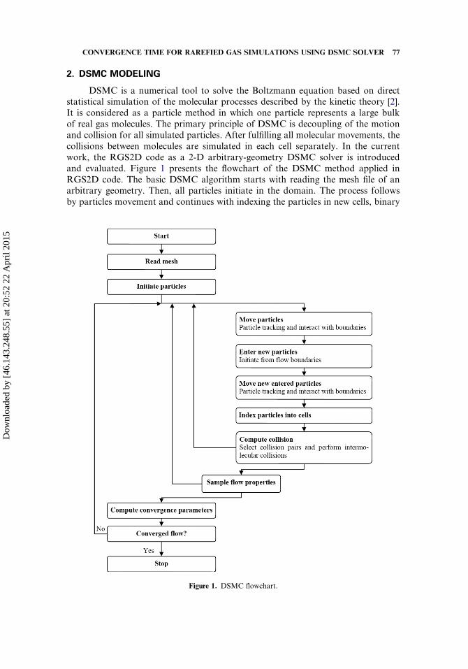
DSMC is a numerical tool to solve the Boltzmann equation based on directstatistical simulation of the molecular processes described by the kinetic theory [2].It is considered as a particle method in which one particle represents a large bulkof real gas molecules. The primary principle of DSMC is decoupling of the motionand collision for all simulated particles. After fulfilling all molecular movements, thecollisions between molecules are simulated in each cell separately. In the currentwork, the RGS2D code as a 2-D arbitrary-geometry DSMC solver is introducedand evaluated. Figure 1 presents the flowchart of the DSMC method applied inRGS2D code. The basic DSMC algorithm starts with reading the mesh file of anarbitrary geometry. Then, all particles initiate in the domain. The process followsby particles movement and continues with indexing the particles in new cells, binary
Figure 1. DSMC flowchart.
CONVERGENCE TIME FOR RAREFIED GAS SIMULATIONS USING DSMC SOLVER 77
Dow
nloa
ded
by [
46.1
43.2
48.5
5] a
t 20:
52 2
2 A
pril
2015
collisions, and flow field sampling. Flow sampling is done after severalmove-collision processes. After a number of flow samplings, convergence parameterscan be checked. In the following sections, details of the RGS2D code and its resultswill be presented.
3. UNSTRUCTURED-MESH DSMC SOLVER
DSMC simulation of rarefied gas subjected to arbitrary geometries with anunstructured mesh requires an efficient particle-tracking algorithm. The current sec-tion presents the details of the RGS2D solver, i.e., algorithms employed for particleinitialization, different boundary conditions implementation, and particle tacking inthe unstructured mesh.
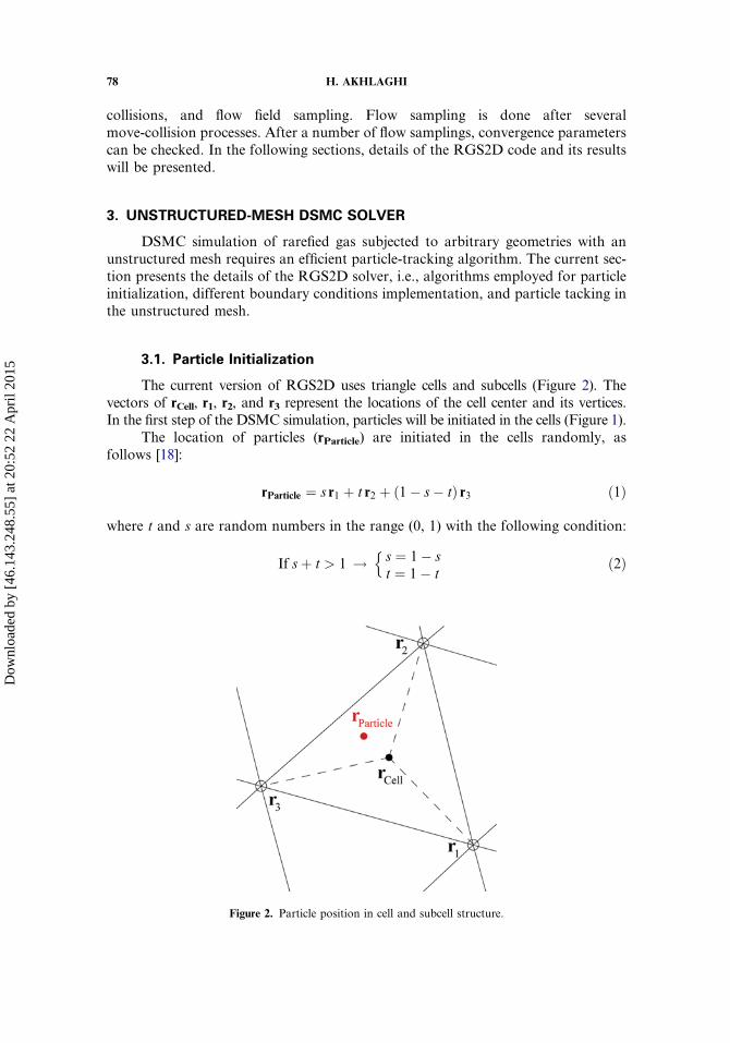
3.1. Particle Initialization
The current version of RGS2D uses triangle cells and subcells (Figure 2). Thevectors of rCell, r1, r2, and r3 represent the locations of the cell center and its vertices.In the first step of the DSMC simulation, particles will be initiated in the cells (Figure 1).
The location of particles (rParticle) are initiated in the cells randomly, asfollows [18]:
rParticle ¼ s r1 þ t r2 þ ð1� s� tÞ r3 ð1Þ
where t and s are random numbers in the range (0, 1) with the following condition:
If sþ t > 1 ! s ¼ 1� st ¼ 1� t
nð2Þ
Figure 2. Particle position in cell and subcell structure.
78 H. AKHLAGHI
Dow
nloa
ded
by [
46.1
43.2
48.5
5] a
t 20:
52 2
2 A
pril
2015
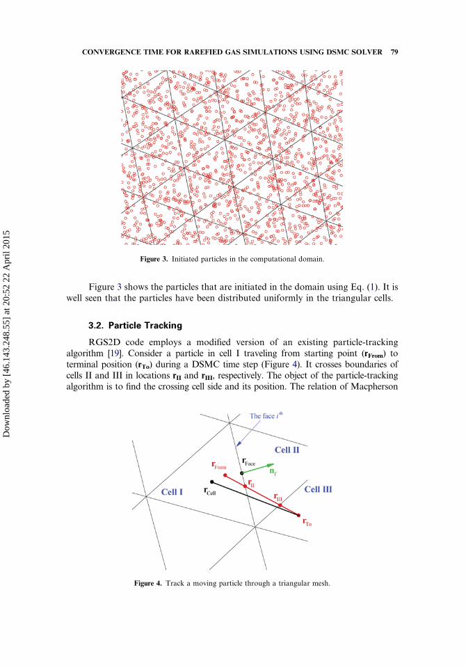
Figure 3 shows the particles that are initiated in the domain using Eq. (1). It iswell seen that the particles have been distributed uniformly in the triangular cells.
3.2. Particle Tracking
RGS2D code employs a modified version of an existing particle-trackingalgorithm [19]. Consider a particle in cell I traveling from starting point (rFrom) toterminal position (rTo) during a DSMC time step (Figure 4). It crosses boundaries ofcells II and III in locations rII and rIII, respectively. The object of the particle-trackingalgorithm is to find the crossing cell side and its position. The relation of Macpherson
Figure 3. Initiated particles in the computational domain.
Figure 4. Track a moving particle through a triangular mesh.
CONVERGENCE TIME FOR RAREFIED GAS SIMULATIONS USING DSMC SOLVER 79
Dow
nloa
ded
by [
46.1
43.2
48.5
5] a
t 20:
52 2
2 A
pril
2015
and Reese [19] for calculation of the crossing point in 2-D space is
rII ¼ rFrom þ K rTo � rFromð Þ ð3Þ
where K is a distance ratio and is defined as [19]
K ¼ rFace � rFromð Þ � nf
rTo � rFromð Þ � nfð4Þ
nf is the outward normal vector for the cell’s side. K is calculated for all sides of the cell.The particle crosses the side corresponding to the minimum value of K. Then, theparticle-tracking process is continued for the neighbor cell with replacement of the valueof rFrom by rII. Whenever the condition 0�K� 1 is not satisfied for each side of the cell,the particle reaches the terminal cell, i.e., cell III in Figure 4. Equation (4) dependson the initial and terminal positions of the particle. On the other hand, the particlesmay be located near the boundaries and corners, and these lead to some numericalproblems in calculation of Eq. (4). Therefore, in this work a modified distance ratiois defined as follows:
Kmod ¼rFace � rCellð Þ � nf
rTo � rCellð Þ � nfð5Þ
Equation (5) depends only on the terminal position of the particle.
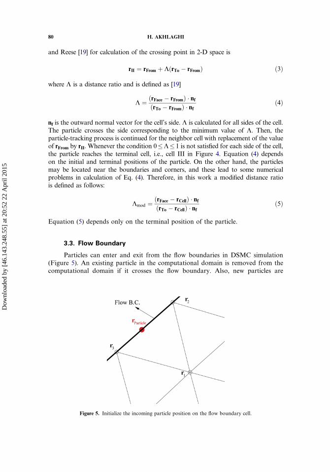
3.3. Flow Boundary
Particles can enter and exit from the flow boundaries in DSMC simulation(Figure 5). An existing particle in the computational domain is removed from thecomputational domain if it crosses the flow boundary. Also, new particles are
Figure 5. Initialize the incoming particle position on the flow boundary cell.
80 H. AKHLAGHI
Dow
nloa
ded
by [
46.1
43.2
48.5
5] a
t 20:
52 2
2 A
pril
2015
entered into the computational domain from the flow boundary based on the macro-scopic properties of the boundary cell. Bird proposed a density flux for incomingparticles based on a Maxwellian velocity distribution function [2, 20].
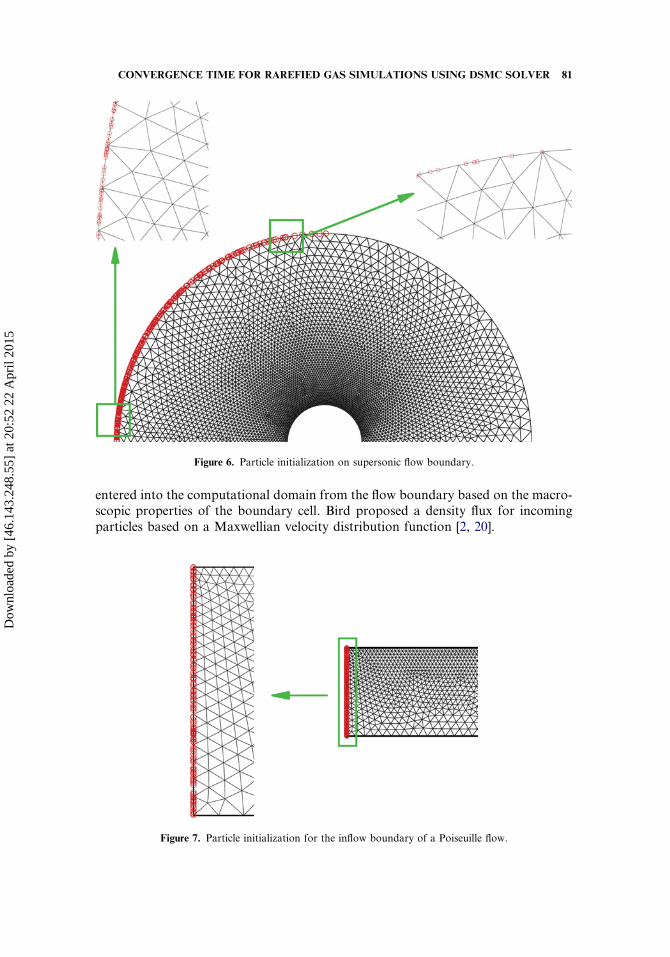
Figure 6. Particle initialization on supersonic flow boundary.
Figure 7. Particle initialization for the inflow boundary of a Poiseuille flow.
CONVERGENCE TIME FOR RAREFIED GAS SIMULATIONS USING DSMC SOLVER 81
Dow
nloa
ded
by [
46.1
43.2
48.5
5] a
t 20:
52 2
2 A
pril
2015
RGS2D code implements four different types of flow boundary treatment:vacuum [20, 21], supersonic flow [20, 21], pressure inlet [22–28], and pressure outlet[22–28]. Vacuum is a flow boundary for internal=external flows in which there is noincoming particle into the domain. In supersonic flow boundary, particles enterbased on the determined and unchanged properties of supersonic flow. Pressureinlet=outlet boundary treatments are applied using an implicit boundary condition[29, 30]. Using this technique, flow macroscopic properties of the boundary cellsare corrected during the simulation to reach specified inlet=outlet pressure values.
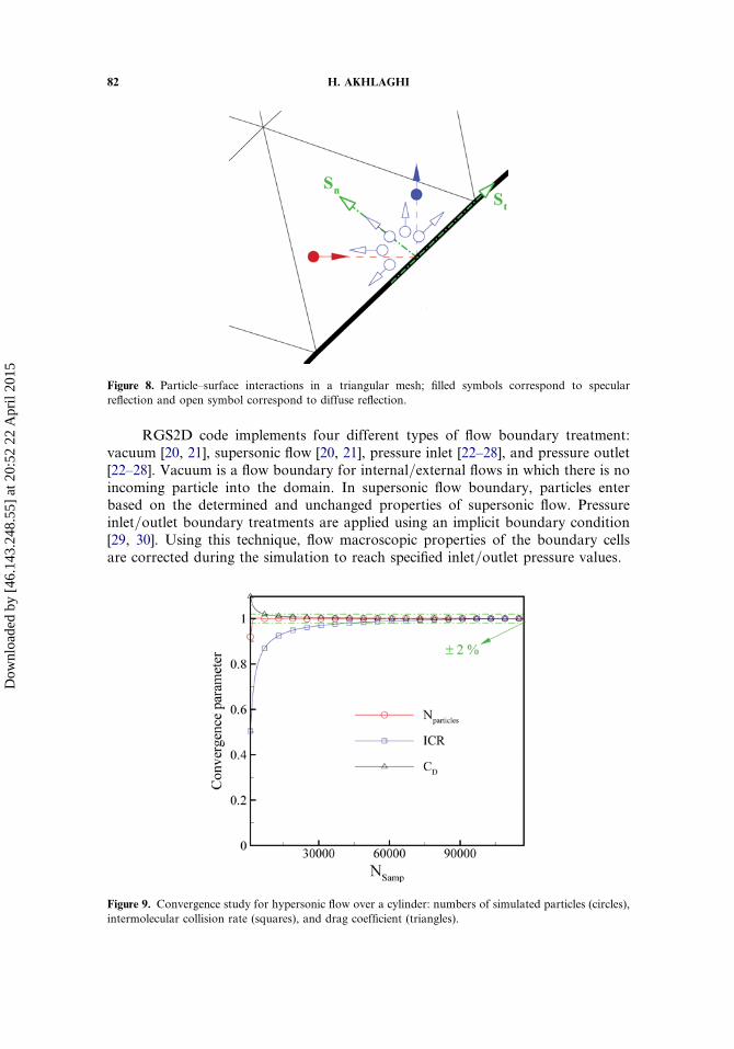
Figure 8. Particle–surface interactions in a triangular mesh; filled symbols correspond to specular
reflection and open symbol correspond to diffuse reflection.
Figure 9. Convergence study for hypersonic flow over a cylinder: numbers of simulated particles (circles),
intermolecular collision rate (squares), and drag coefficient (triangles).
82 H. AKHLAGHI
Dow
nloa
ded
by [
46.1
43.2
48.5
5] a
t 20:
52 2
2 A
pril
2015
After assigning velocity and internal energy values for incoming particles, it isrequired to initialize particles in the flow boundaries. This is done through Eq. (6):
rParticle ¼ sðr3 � r2Þ ð6Þ
where s is a random number between 0 and 1. r3 and r2 are position vectors ofboundary nodes. Figures 6 and 7 illustrate the particles initialized over the flowboundaries for two different cases. Figure 6 corresponds to hypersonic flow overa cylinder. As is seen, the particles have been uniformly distributed along eachboundary cell. But density flux is different for each boundary cell side due toboundary-side inclination with respect to the stream flow. Because of the hypersonicstream flow, there are approximately no incoming particles for boundary cells in theback side of the cylinder.
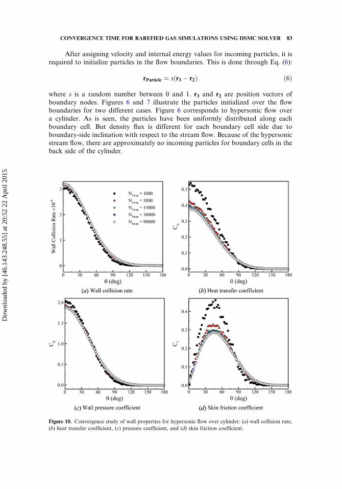
Figure 10. Convergence study of wall properties for hypersonic flow over cylinder: (a) wall collision rate,
(b) heat transfer coefficient, (c) pressure coefficient, and (d) skin friction coefficient.
CONVERGENCE TIME FOR RAREFIED GAS SIMULATIONS USING DSMC SOLVER 83
Dow
nloa
ded
by [
46.1
43.2
48.5
5] a
t 20:
52 2
2 A
pril
2015
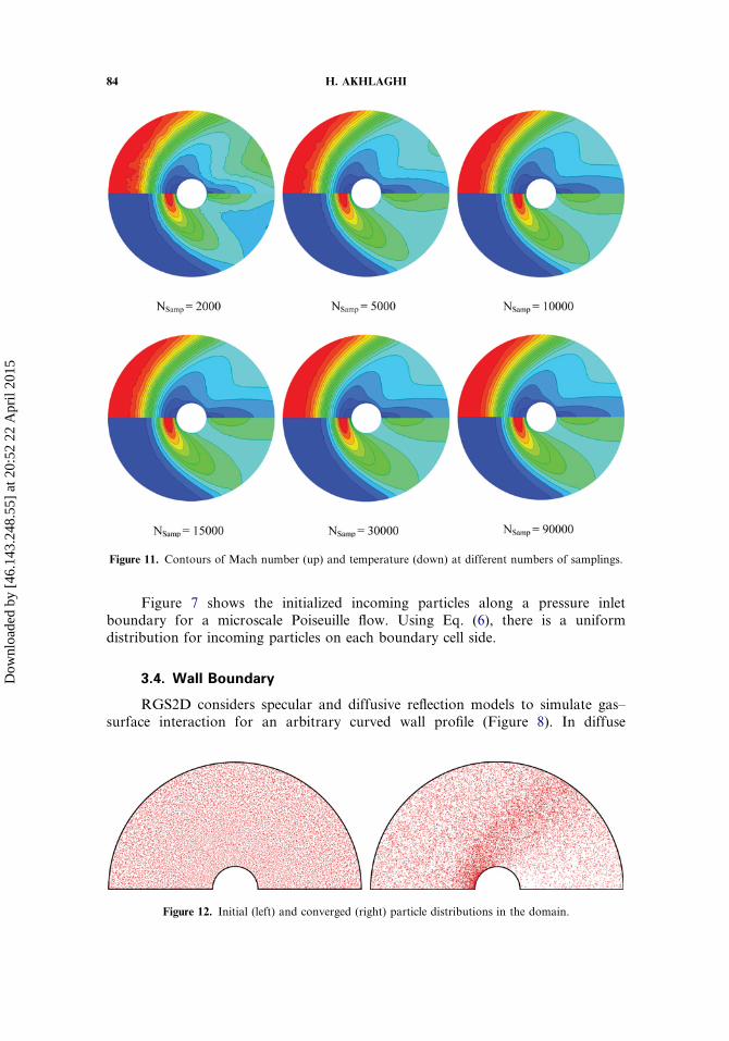
Figure 7 shows the initialized incoming particles along a pressure inletboundary for a microscale Poiseuille flow. Using Eq. (6), there is a uniformdistribution for incoming particles on each boundary cell side.
3.4. Wall Boundary
RGS2D considers specular and diffusive reflection models to simulate gas–surface interaction for an arbitrary curved wall profile (Figure 8). In diffuse
Figure 11. Contours of Mach number (up) and temperature (down) at different numbers of samplings.
Figure 12. Initial (left) and converged (right) particle distributions in the domain.
84 H. AKHLAGHI
Dow
nloa
ded
by [
46.1
43.2
48.5
5] a
t 20:
52 2
2 A
pril
2015
reflection, the emission of impinging molecules is not correlated with the pre-impingement state of the molecules [2]. According to Figure 8, in diffuse reflection,the outgoing velocity of a molecule is randomly assigned according to a half-rangeMaxwellian distribution determined by the wall temperature. For specular reflection,the incident angle is equal to the reflection angle and there is no loss in gas–surfaceinteraction. Diffusive and specular reflections in RGS2D code are performed basedon the tangential (St) and normal (Sn) vectors of the wall cell side. Classical DSMCsimulation is based on specified wall temperature (SWT) condition. RGS2D addition-ally can simulate the wall under specified wall heat flux (SWH) condition [21].
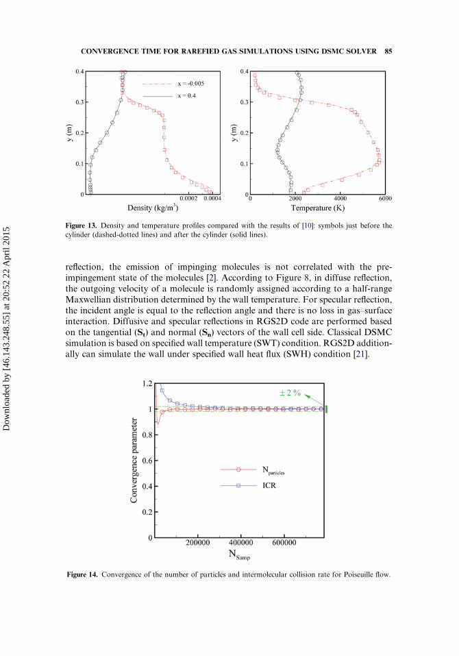
Figure 13. Density and temperature profiles compared with the results of [10]: symbols just before the
cylinder (dashed-dotted lines) and after the cylinder (solid lines).
Figure 14. Convergence of the number of particles and intermolecular collision rate for Poiseuille flow.
CONVERGENCE TIME FOR RAREFIED GAS SIMULATIONS USING DSMC SOLVER 85
Dow
nloa
ded
by [
46.1
43.2
48.5
5] a
t 20:
52 2
2 A
pril
2015
In the next sections the results of RGS2D for two different cases are presented.The results contain convergence time study of RGS2D code and some verificationfor hypersonic rarefied gas flow over a cylinder and Poiseuille flow througha microchannel. The variable hard sphere (VHS) model is applied as the intermole-cular collision model [2], and argon is used as the working gas in all simulations.
4. HYPERSONIC FLOW OVER A CYLINDER
In this section the results of RGS2D for hypersonic flow over a cylinder arepresented. The test case corresponds to [6], in which the flow Mach number is 10and the cylinder diameter is 12 in. (0.3048 m). Figure 9 shows the variations innumber of simulated particles (Nparticles), intermolecular collision rate (ICR), anddrag coefficient (CD) during the DSMC simulation as the number of samplingsincreases. The vertical axis is the convergence parameter, which is obtained fromnormalization with converged values. As is seen, the results approach to convergedvalues as the number of samplings increases. A convergence criterion is definedas �2% deviation from the final value of the capturing parameter. According toFigure 9, the convergence for Nparticles is the fastest and for ICR is the slowest.
Figure 10 investigates the convergence time for the properties distributions onthe wall. The wall distributions, i.e., particle–surface collision rate, heat transfercoefficient, wall pressure coefficient, and skin friction coefficient, are plottedrespectively in Figures 10a, 10b, 10c, and 10d at different numbers of samplingsituations, which correspond to different simulation times. According to the results,wall collision rate and pressure coefficient distributions converges for NSamp> 1,000.But convergence for heat transfer coefficient and skin friction coefficient distributions
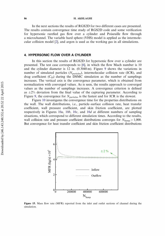
Figure 15. Mass flow rate (MFR) reported from the inlet and outlet sections of channel during the
simulation.
86 H. AKHLAGHI
Dow
nloa
ded
by [
46.1
43.2
48.5
5] a
t 20:
52 2
2 A
pril
2015
is achieved at larger number of samplings (NSamp> 15,000). Maximum values ofwall collision rate, heat transfer coefficient, and pressure coefficient occur at h¼ 0�
which corresponds to the stagnation point of the cylinder. Maximum value of skinfriction coefficient arises at h’ 45�. As flow approaches to the back side of thecylinder, particle–surface collision rate and consequently other wall propertiesapproach to zero.
Figure 11 shows the Mach (up) and temperature (down) fields during the simu-lation. There are big noises in the domain at the initial steps of simulation. As thenumber of samplings increases, the noises shrink and the contours become smoother.It is also well seen that the initial noises in Mach contours are more severe comparedto those of temperature. Convergence for the temperature field is faster. However,converged field results would be obtained for NSamp> 15,000. According toFigure 11, the flow in the front of the cylinder has crossed through strong shock
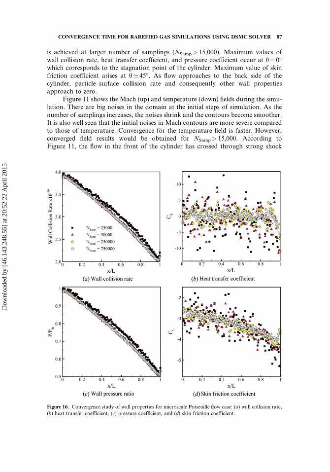
Figure 16. Convergence study of wall properties for microscale Poiseuille flow case: (a) wall collision rate,
(b) heat transfer coefficient, (c) pressure coefficient, and (d) skin friction coefficient.
CONVERGENCE TIME FOR RAREFIED GAS SIMULATIONS USING DSMC SOLVER 87
Dow
nloa
ded
by [
46.1
43.2
48.5
5] a
t 20:
52 2
2 A
pril
2015
and it becomes subsonic and its temperature increases. As the flow crosses over thecylinder, it decelerates and its temperature increases.
Figure 12 depicts the initial and converged particles distribution in the domain.It is seen that the particle density is higher at the shock location and it is lowerbehind the cylinder. Figure 13 compares the obtained density and temperatureprofiles with those of Su et al. [6]. There is good agreement between the resultsin high-density (front) and low-density (back) regions. In the front region, densityand temperature are higher near the wall because of shock effect. But in the backregion, density and temperature are lower near the wall because of the existenceof a low-density region.
5. POISEUILLE FLOW THROUGH A MICROCHANNEL
At this point, the ability of RGS2D in simulation of microscale flows will beevaluated. For this, Poiseuille flow through a microchannel has been considered.The channel width and length are 1 mm and 20 mm, respectively. A nonuniformtriangular mesh is employed (Figure 7).
Figure 14 demonstrates the variations of Nparticles (circles) and intermolecularcollision rate (squares) versus number of sampling (or simulation time). Similar tothe previous case, the convergence time for Nparticles is smaller than that of collisionrate. Figure 15 shows the convergence from balancing between inlet (solid lines) andoutlet (dashed lines) mass flow rates. According to the results, convergence for inletMFR is faster. One reason is that the flow field has been initiated based on the inflowcondition. Comparing Figures 14 and 15, one can conclude that balancing betweeninlet and outlet MFR values is achieved after intermolecular collision rate is reached.
Figure 16 investigates the convergence for the wall properties. The walldistributions, i.e., particle–surface collision rate, heat transfer coefficient, wallpressure ratio, and skin friction coefficient, are plotted respectively in Figures 16a,
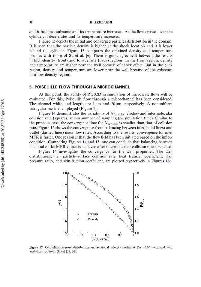
Figure 17. Centerline pressure distribution and sectional velocity profile at Kn¼ 0.05 compared with
analytical solutions (lines) [31, 32].
88 H. AKHLAGHI
Dow
nloa
ded
by [
46.1
43.2
48.5
5] a
t 20:
52 2
2 A
pril
2015
16b, 16c, and 16d at different simulation times. According to Figures 16a and 16c theconverged distributions for particle–surface collision rate and wall pressure ratio areachieved at NSamp> 25,000. Convergence for heat transfer coefficient (Figure 16b) andskin friction coefficient distributions (Figure 16d) is slower and occurs atNSamp> 50,000. It can be concluded that slower convergence in Figures 16b and16d is due to the existence of large scattering in the tangential velocity component.It is also well seen that for NSamp> 50,000, significant fluctuations in wall propertiesdistributions will be diminished.
As a validation of RGS2D code, Figure 17 compares the centerline pressuredistribution (squares) and velocity profile (circles) at a section corresponding toKn¼ 0.05, with analytical relations (lines) presented in [31] and [32]. As seen, thereis good agreement between the present results and the analytical relations. It can beconcluded that RGS2D code is reliable enough for future simulations of rarefied gasat macro-=microscale.
6. CONCLUSION
This article introduced and evaluated an arbitrary-geometry DSMC solvernamed RGS2D for rarefied gas simulation in micro-=macro-scale applications.The details of algorithms employed for particle initialization, modifiedparticle-tracking procedure in unstructured mesh, and implemented boundary con-ditions in RGS2D code were presented. The present work focused on the conver-gence time of DSMC simulations based on the different macroscopic=microscopiccapturing parameters. Captured parameters were number of simulated particles,intermolecular collision rate, drag coefficient, inlet=outlet mass flow rate, domaincontours, particle–surface collision rate, wall heat transfer collision rate, skin frictioncollision rate, and wall pressure distribution. The results indicated that convergencefor macroscopic properties occurs after the collision rate has converged. Number ofparticles is the parameter which has the lowest convergence time. Among wallproperties, the convergence is slower for which contains the tangential velocitycomponent. Comparison with benchmark and existing analytical relations showedthat RGS2D code is reliable enough for future simulations of rarefied gas at macro-and microscales.
REFERENCES
1. C. Cercignani, The Boltzmann Equation and its Applications, Springer-Verlag, New York,1988.
2. G. A. Bird, Molecular Gas Dynamics and the Direct Simulation of Gas Flows, Oxford
University Press, Oxford, UK, 1994.3. G. A. Bird, Monte Carlo Simulation of Gas Flows, Annu. Rev. Fluid Mech., vol. 10,
pp. 11–31, 1978.
4. T. Zhu and W. Ye, Theoretical and Numerical Studies of Noncontinuum Gas-Phase HeatConduction in Micro=Nano Devices, Num. Heat Transfer B, vol. 57, pp. 203–226, 2010.
5. F. B. Bao and J. Z. Lin, Continuum Simulation of the Microscale Backward-Facing StepFlow in a Transition Regime, Num. Heat Transfer A, vol. 59, pp. 616–632, 2011.
CONVERGENCE TIME FOR RAREFIED GAS SIMULATIONS USING DSMC SOLVER 89
Dow
nloa
ded
by [
46.1
43.2
48.5
5] a
t 20:
52 2
2 A
pril
2015
6. M. Roesle, P. Good, V. Coskun, and A. Steinfeld, Analysis of Conduction Heat Lossfrom a Parabolic Trough Solar Receiver with Active Vacuum by Direct Simulation MonteCarlo, Num. Heat Transfer A, vol. 62, pp. 432–444, 2012.
7. F. Memarian and K. J. Daun, Gas Dynamics of Sublimed Nanoclusters in High-Fluence Time-Resolved Laser-Induced Incandescence, Num. Heat Transfer B, vol. 65,pp. 393–409, 2014.
8. S. K. Stefanov, V. Roussinov, and C. Cercignani, Rayleigh–Benard Flow of a RarefiedGas and Its Attractors. I. Convection Regime, Phys. Fluids, vol. 14, pp. 2255–2269, 2002.
9. G. A. Bird, The DS2 V=3V Program Suite for DSMC Calculations, Rarefied GasDynamics, 24th International Symposium on Rarefied Gas Dynamics, Bari, Italy, vol. 762,pp. 541–546, American Institute of Physics, 2005.
10. C. C. Su, K. C. Tseng, J. S. Wu, H. M. Cave, M. C. Jermy, and Y. Y. Lian, Two-LevelVirtual Mesh Refinement Algorithm in a Parallelized DSMC Code Using UnstructuredGrids, Comput. Fluids, vol. 48, pp. 113–124, 2011.
11. M. A. Gallis, J. R. Torczynski, D. J. Rader, and G. A. Bird, Convergence Behavior ofa New DSMC Algorithm, J. Comput. Phys., vol. 228, pp. 4532–4548, 2009.
12. M. A. Gallis and J. R. Torczynski, Efficient DSMC Collision-Partner Selection Schemes,AIP Con. Proc., vol. 1333, pp. 248–254, 2011.
13. J. M. Burt and I. D. Boyd, Novel Cartesian Implementation of the Direct SimulationMonte Carlo Method, J. Thermophys. Heat Transfer, vol. 26, pp. 258–270, 2012.
14. S. K. Stefanov, On DSMC Calculation of Rarefied Gas Flows with Small Number ofParticles in Cells, SIAM J. Sci. Comput., vol. 33, pp. 677–702, 2011.
15. S. K. Stefanov, Particle Monte Carlo Algorithms with Small Number of Particles in GridCells, in I. Dimov (ed.), Numerical Methods and Applications, Lecture Notes in ComputerScience, vol. 6046, pp. 110–117, 2011.
16. A. Mohammadzadeh, E. Roohi, and H. Niazmand, A Parallel DSMC Investigationof Monatomic=Diatomic Gas Flows in a Micro=Nano Cavity, Num. Heat Transfer, A,vol. 63, pp. 305–325, 2013.
17. A. Amiri, E. Roohi, H. Nami, H. Niazmand, and S. K. Stefanov, DSMC Simulation ofMicro=Nano Flows Using SBT-TAS Technique, Comput. Fluids, vol. 102, pp. 266–276,2014.
18. A. S. Glassner, Graphics Gems, Academic Press, Orlando, FL, 1990.19. G. B. Macpherson and J. M. Reese, Molecular Dynamics in Arbitrary Geometries:
Parallel Evaluation of Pair Forces, Molec. Simul., vol. 34, pp. 97–115, 2008.20. A. Rangrazi, E. Roohi, and H. Akhlaghi, Study of Physical Aspects of Rarefied Gas Flow
through Micro=Nano Scale Channels Using DSMC, Arabian J. Sci. Eng., vol. 39, pp.2331–2338, 2014.
21. H. Akhlaghi, M. Balaj, and E. Roohi, Direct Simulation Monte Carlo Investigation ofMixed Supersonic–Subsonic Flow through Micro-=Nano-Scale Channels, PhysicaScripta, vol. 88, 015401-8, 2013.
22. H. Akhlaghi, E. Roohi, and S. K. Stefanov, A New Iterative Wall Heat Flux SpecifyingTechnique in DSMC for Heating=Cooling Simulations of MEMS=NEMS, Int. J. ThermalSci., vol. 59, pp. 111–125, 2012.
23. H. Akhlaghi, M. Balaj, and E. Roohi, Hydrodynamic Behavior of Micro=NanoscalePoiseuille Flow under Thermal Creep Condition, Appl. Phys. Lett., vol. 103, 073108-5, 2013.
24. H. Akhlaghi and E. Roohi, Mass Flow Rate Prediction of Pressure-Temperature-DrivenGas Flows through Micro=Nanoscale Channels, Continuum Mech. Thermodynam., vol. 26,pp. 67–78, 2014.
25. M. Balaj, E. Roohi, H. Akhlaghi, and R. S. Myong, Investigation of Convective HeatTransfer through Constant Wall Heat Flux Micro=Nano Channels Using DSMC, Int.J. Heat Mass Transfer, vol. 71, pp. 633–638, 2014.
90 H. AKHLAGHI
Dow
nloa
ded
by [
46.1
43.2
48.5
5] a
t 20:
52 2
2 A
pril
2015
26. H. Akhlaghi, E. Roohi, and M. Balaj, A Thorough Study on Thermal Mass Flux ofRarefied Flow through Micro=Nanochannels, Appl. Phys. Lett., vol. 104, 073109-5, 2014.
27. H. Akhlaghi, E. Roohi, M. Balaj, and K. S. Dadzie, Wall Heat Transfer Effectson the Hydro=Thermal Behavior of Poiseuille Flow in Micro=Nanochannels, Phys. Fluids,vol. 26, 092002-11, 2014.
28. A. M. Mahdavi, N. T. P. Le, E. Roohi, and C. White, Thermal Rarefied Gas FlowInvestigations through Micro=Nano Backward-Facing Step: Comparison of DSMC andCFD Subject to Hybrid Slip and Jump Boundary Conditions, Num. Heat Transfer A,
vol. 66, pp. 733–755, 2014.29. W. Liou and Y. Fang, Implicit Boundary Conditions for Direct Simulation Monte Carlo
Method in MEMS Flow Predictions, Comput. Model. Eng. Sci., vol. 1, pp. 119–128, 2000.30. M. Wang and Z. Li, Simulations for Gas Flows in Microgeometries Using the Direct
Simulation Monte Carlo Method, Int. J. Heat Fluid Flow, vol. 25, pp. 975–985, 2004.31. A. Beskok and G. E. Karniadakis, Report: A Model for Flows in Channels, Pipes, and
Ducts at Micro and Nano Scales, Nanoscale Microscale Thermophys. Eng., vol. 3,
pp. 43–77, 1999.32. N. Dongari, A. Agrawal, and A. Agrawal, Analytical Solution of Gaseous Slip Flow
in Long Microchannels, Int. J. Heat Mass Transfer, vol. 50, pp. 3411–3421, 2007.
CONVERGENCE TIME FOR RAREFIED GAS SIMULATIONS USING DSMC SOLVER 91
Dow
nloa
ded
by [
46.1
43.2
48.5
5] a
t 20:
52 2
2 A
pril
2015


![Reflecting Rarefied Wellness [Hotel Business Review, Jan-Feb 2016]](https://img.pdfslide.net/doc/110x75/58a5c8c51a28ab6c2a8b4eab/reflecting-rarefied-wellness-hotel-business-review-jan-feb-2016.jpg)

