Embed Size (px)
Citation preview
Kent Academic RepositoryFull text document (pdf)
Copyright & reuse
Content in the Kent Academic Repository is made available for research purposes. Unless otherwise stated all
content is protected by copyright and in the absence of an open licence (eg Creative Commons), permissions
for further reuse of content should be sought from the publisher, author or other copyright holder.
Versions of research
The version in the Kent Academic Repository may differ from the final published version.
Users are advised to check http://kar.kent.ac.uk for the status of the paper. Users should always cite the
published version of record.
Enquiries
For any further enquiries regarding the licence status of this document, please contact:
If you believe this document infringes copyright then please contact the KAR admin team with the take-down
information provided at http://kar.kent.ac.uk/contact.html
Citation for published version
Sanz-Izquierdo, Benito and Parker, Edward A. and Robertson, J.-B. and Batchelor, John C. (2010)Singly and Dual Polarized Convoluted Frequency Selective Structures. IEEE Transactions onAntennas and Propagation, 58 (3). pp. 690-696. ISSN 0018-926X.
DOI
http://doi.org/10.1109/TAP.2009.2039321
Link to record in KAR
http://kar.kent.ac.uk/24223/
Document Version
Author's Accepted Manuscript
Singly and Dual Polarised Convoluted Frequency Selective Structures B. Sanz-Izquierdo, E. A. Parker, J.-B. Robertson and J. C. Batchelor Department of Electronics, University of Kent, Canterbury CT2 7NT This is an accepted pre-published version of this paper. © 2010 IEEE. Personal use of this material is permitted. Permission from IEEE must be obtained for all other uses, in any current or future media, including reprinting/republishing this material for advertising or promotional purposes, creating new collective works, for resale or redistribution to servers or lists, or reuse of any copyrighted component of this work in other works. The link to this paper on IEEE Xplore® is http://ieeexplore.ieee.org/xpl/articleDetails.jsp?tp=&arnumber=5372013&queryText%3Dsingly+and+dual+polarised+convoluted+frequency+selective+structures The DOI is: http://dx.doi.10.1109/TAP.2009.2039321
Singly and Dual Polarised Convoluted Frequency Selective Structures
B. Sanz-Izquierdo, E. A. Parker, J.-B. Robertson and J. C. Batchelor Department of Electronics, University of Kent, Canterbury CT2 7NT
Abstract: Convoluting the elements of Frequency Selective Surfaces produces resonating structures with very small unit cell dimensions. This feature is attractive when the FSS is to be used at low frequencies, mounted on a curved surface, or when placed in the proximity of compact radiators. The characteristics of single and dual polarised convoluted FSS are analysed and measured. The development of novel convoluted elements derived from the square loop slot is traced and their performance is examined. A novel technique of interweaving convoluted loops allows for further cell size reduction, while increasing the passband width, introducing flexibility in wideband FSS design, particularly for tailoring the Electromagnetic Architecture of buildings, and mobile communications in the built environment. Simulated transmission responses of the convoluted structures are in good agreement with the measurements. Index Terms— Convoluted elements, fractals, frequency selective surfaces, Electromagnetic Architecture, built environment 1. Introduction There is an increasing interest in applying frequency selective surface to wireless communications systems with the purpose of controlling the Electromagnetic Architecture of Buildings (EAoB) [1-4]. One problem that FSS encounter when applied to buildings is that the wavelengths in the bands used by most of the mobile, radio and wireless technologies employed in indoor communications are not insignificant when compared with the size of an ordinary office room. For example, the 400 MHz band employed for general mobile radio systems (GMRS) in the USA and personal mobile radio systems (PMR446) and the emergency TETRA in Europe has a corresponding wavelength of 750mm, only 4 times smaller than the average floor-ceiling height in a building. Convoluting array the elements of an FSS [5] could play an important role in the future EAoB as they can considerably reduce the size of the unit cell and perform well when incorporated into curved surfaces. In addition, convoluting FSS elements improves the angular stability of the frequency responses of the surface, moving the operating bands away from the grating region determined by the periodicity of the array [5-8]. The Hilbert curves are a family of space filling curves that can be produced using simple mathematical formulation [9]. The Hilbert curve offers the attractive property of being able to compact an electrically long wire within a very small space. The geometry has been applied to produce compact antennas [10 – 12], frequency selective surfaces [5] and high impedance surfaces (HIP) [13].
Previous research studies of convoluted frequency selective surfaces [5-8] include single and dual polarised versions of these structures. It was in [5] where the term “convoluted” was first used to describe complex arrays of printed RF structures which exhibit long wavelength resonances in a surface with small periodicity. From simple arrays of linear dipoles [6], the concept was further developed using Hilbert curves in [5] and cross dipoles in [7]. The effectiveness of this process was judged by the figure of merit � 1/p and the ratio L/1, where 1 is the corresponding free space wavelength, p is the lattice periodicity and L is the total length of the conductor in the element. Recently, several papers [14], [15] have presented convoluted frequency selective surfaces whose elements extend beyond the unit cell into the neighbouring cells using a method termed as “interweaving” in [15]. The characteristics of these structures are similar to those exhibited by square spiral elements described in [16] which were developed in Mission Research Corporation, Dayton, Ohio. Interweaving was initially applied to high impedance surfaces (HIP) [17] in [18] using the convoluted cross dipoles of the type described in [7]. In [18], miniaturisation was achieved at the expense of a reduction in the bandwidth of the HIP. This is in contrast with the bandwidth enhancement properties of these configurations when employed as FSS [14, 15].
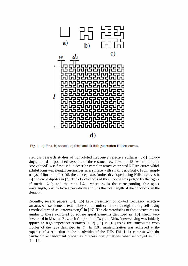
This paper studies the miniaturization of the unit cells of frequency selective surfaces and their transmission responses. The first section adds a further iteration of the Hilbert geometry to the sequence previously published in [5]. Note, though, that in this paper, the elements are in slot form, to give bandpass transmission responses. Later sections look at novel developments of convoluted loops, and interweaving. The paper ends with a case study of the application of interwoven elements. II. HIGHLY CONVOLUTED HILBERT CURVE STRUCTURES FOR UHF APPLICATIONS A. Hilbert geometry Fig. 1 illustrates the first, second, third and fifth generation of the Hilbert curve [8]. The curves are generated by way of Lindenmayer system [19] and each generation is composed of segments of length dn and 2dn, where the generation number n, dn and the side l of the square are related by
(2n-1) dn = l (1) Frequency selective surfaces based on the first, third and four generations in [5] were able to reduce sequentially the unit cell size to below 10 percent of the free space wavelength at resonance, illustrated by the figure of merit � 1/p. A slot version of the fifth generation (Fig.1d) has now been developed in order to achieve resonant frequencies below 1GHz, with higher figure of merit than reported in [5]. The dimensions chosen were d5 = 0.44 mm, l = 13.73 mm, and p = 14.3 mm, the periodicity of the regular square lattice. The width of the slot was w = 0.25 mm, the influence of the slot width is discussed later. The FSS was etched into a copper clad polyester supporting substrate 0.03mm thick, with � r = 3. This material was used throughout the work reported here. Simulated and measured transmission responses for an array of these fifth generation elements are shown in Figs. 2 and 3. Simulations were carried out using the frequency domain solver included in CST Microwave StudioTM. B. Measurements As the Hilbert curve begins and ends at adjacent corners, the element is not symmetrical and therefore is singly polarised. The frequency selective slot structure was placed in an aperture of approximately 200mm 200mm, surrounded by a high frequency absorbing board of 1.52m 1.95m for testing purposes. At the long wavelengths employed here, measured transmission levels are likely to be perturbed by scattered signals [4]. Two sets of independent measurements were therefore carried out and compared.
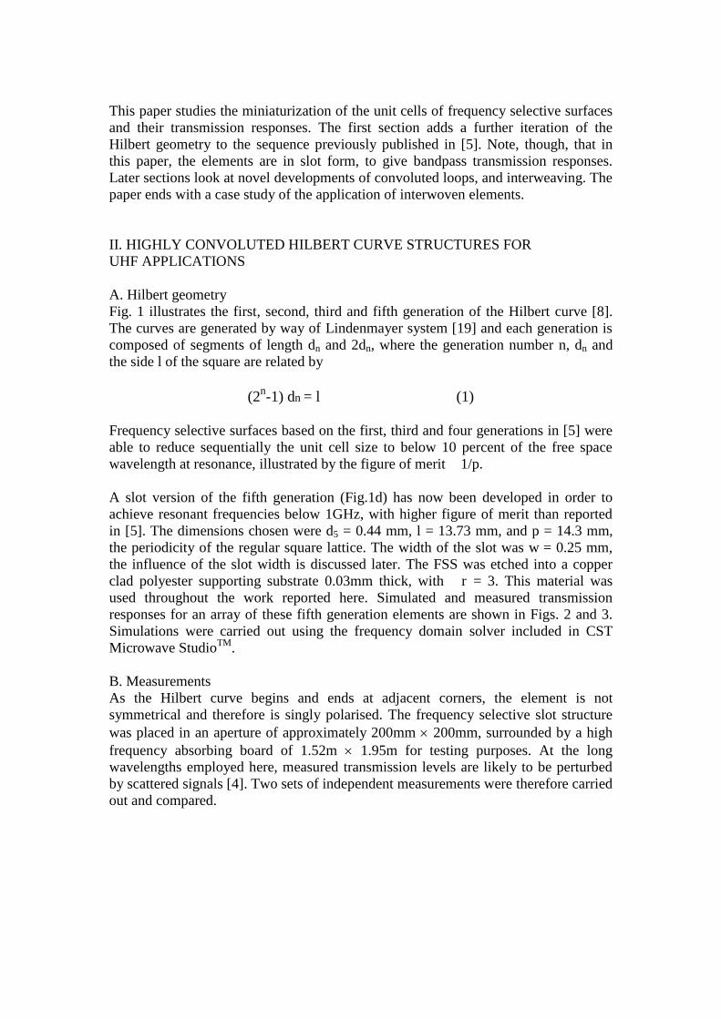
In the first, two log periodic antennas, the signal source and the receiver, were each placed 1 metre from the centre of the FSS. Transmission levels were calibrated relative to that of the open aperture. Below 1 GHz multipath and leakage problems were significant. So as a trial, the log periodic transmitter were replaced by a broadband biconical dipole antenna placed in close proximity to the array, at a distance of only 5 cm, while the log-periodic receiver remained at 1m from the FSS. Fig. 2 shows the transmission response when the electric field was aligned parallel to the open side of the element square (Fig.1d). There are resonances at about 1.6 GHz and 2.6 GHz, with measurements and plane wave simulations predicting well the behaviour of the FSS. There is very little difference between the two sets of measurements, although the frequencies of maximum transmission are marginally higher than predicted by the simulation. The subsequent measurements in this paper were all carried out with the biconical antenna. Fig. 3 shows the transmission curve when the electric field was perpendicular to the open side of the square. Resonances occur at 0.75GHz and 1.8GHz, with a very high figure of merit at the first resonance: 1/p = 28. Table I summarises the characteristics of singly polarised (SP) arrays presented in [5], with the addition of the fifth generation of the Hilbert curve for MHz applications. At the time that [5] was written, we were unable to make measurements at the very long wavelengths where the presence of the low frequency resonance for the fourth generation was suspected to exist, but that problem has been overcome and plane
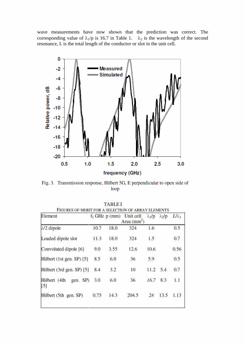
wave measurements have now shown that the prediction was correct. The corresponding value of 1/p is 16.7 in Table 1. �2 is the wavelength of the second resonance, L is the total length of the conductor or slot in the unit cell.
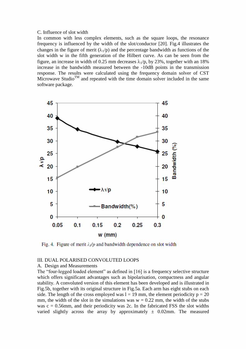
C. Influence of slot width In common with less complex elements, such as the square loops, the resonance frequency is influenced by the width of the slot/conductor [20]. Fig.4 illustrates the changes in the figure of merit (1/p) and the percentage bandwidth as functions of the slot width w in the fifth generation of the Hilbert curve. As can be seen from the figure, an increase in width of 0.25 mm decreases 1/p, by 23%, together with an 18% increase in the bandwidth measured between the -10dB points in the transmission response. The results were calculated using the frequency domain solver of CST Microwave StudioTM and repeated with the time domain solver included in the same software package.
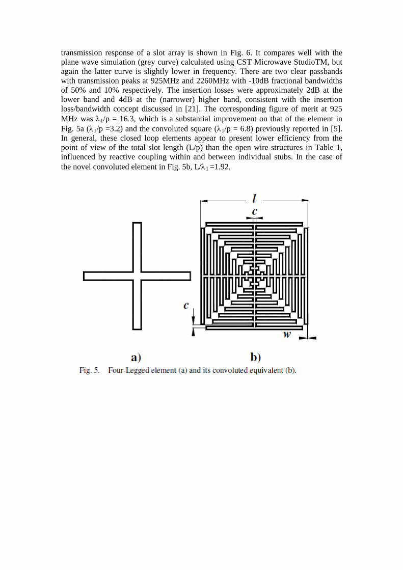
III. DUAL POLARISED CONVOLUTED LOOPS A. Design and Measurements The “four-legged loaded element” as defined in [16] is a frequency selective structure which offers significant advantages such as bipolarisation, compactness and angular stability. A convoluted version of this element has been developed and is illustrated in Fig.5b, together with its original structure in Fig.5a. Each arm has eight stubs on each side. The length of the cross employed was l = 19 mm, the element periodicity p = 20 mm, the width of the slot in the simulations was w = 0.22 mm, the width of the stubs was c = 0.56mm, and their periodicity was 2c. In the fabricated FSS the slot widths varied slightly across the array by approximately ± 0.02mm. The measured
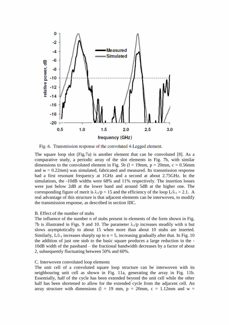
transmission response of a slot array is shown in Fig. 6. It compares well with the plane wave simulation (grey curve) calculated using CST Microwave StudioTM, but again the latter curve is slightly lower in frequency. There are two clear passbands with transmission peaks at 925MHz and 2260MHz with -10dB fractional bandwidths of 50% and 10% respectively. The insertion losses were approximately 2dB at the lower band and 4dB at the (narrower) higher band, consistent with the insertion loss/bandwidth concept discussed in [21]. The corresponding figure of merit at 925 MHz was 1/p = 16.3, which is a substantial improvement on that of the element in Fig. 5a (1/p =3.2) and the convoluted square (1/p = 6.8) previously reported in [5]. In general, these closed loop elements appear to present lower efficiency from the point of view of the total slot length (L/p) than the open wire structures in Table 1, influenced by reactive coupling within and between individual stubs. In the case of the novel convoluted element in Fig. 5b, L/1 =1.92.
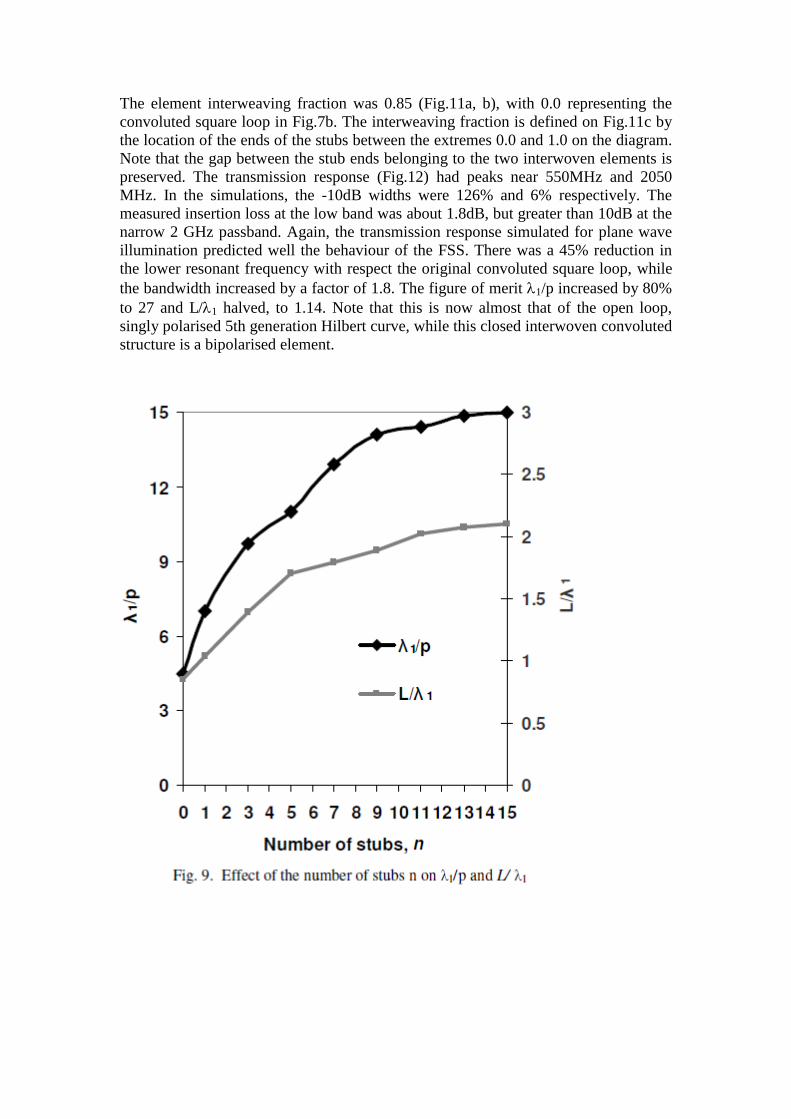
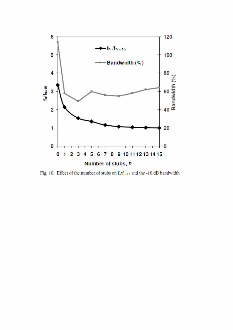
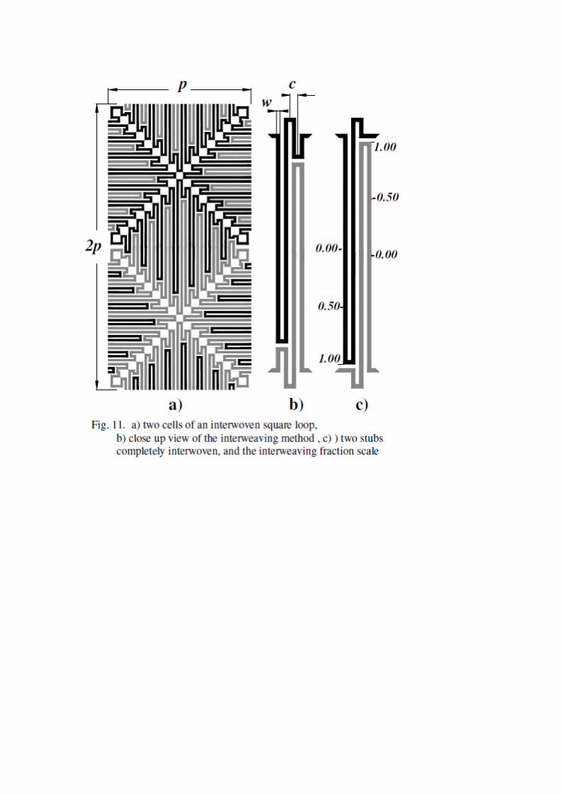
The square loop slot (Fig.7a) is another element that can be convoluted [8]. As a comparative study, a periodic array of the slot elements in Fig. 7b, with similar dimensions to the convoluted element in Fig. 5b (l = 19mm, p = 20mm, c = 0.56mm and w = 0.22mm) was simulated, fabricated and measured. Its transmission response had a first resonant frequency at 1GHz and a second at about 2.75GHz. In the simulations, the -10dB widths were 68% and 11% respectively. The insertion losses were just below 2dB at the lower band and around 5dB at the higher one. The corresponding figure of merit is 1/p = 15 and the efficiency of the loop L/1 = 2.1. A real advantage of this structure is that adjacent elements can be interwoven, to modify the transmission response, as described in section IIIC. B. Effect of the number of stubs The influence of the number n of stubs present in elements of the form shown in Fig. 7b is illustrated in Figs. 9 and 10. The parameter 1/p increases steadily with n but slows asymptotically to about 15 when more than about 10 stubs are inserted. Similarly, L/1 increases sharply up to n = 5, increasing gradually after that. In Fig. 10 the addition of just one stub to the basic square produces a large reduction in the - 10dB width of the passband – the fractional bandwidth decreases by a factor of about 2, subsequently fluctuating between 50% and 60%. C. Interwoven convoluted loop elements The unit cell of a convoluted square loop structure can be interwoven with its neighbouring unit cell as shown in Fig. 11a, generating the array in Fig. 11b. Essentially, half of the cycle has been extended beyond the unit cell while the other half has been shortened to allow for the extended cycle from the adjacent cell. An array structure with dimensions (l = 19 mm, p = 20mm, c = 1.12mm and w =
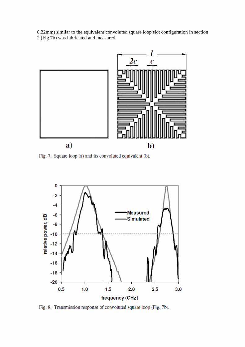
0.22mm) similar to the equivalent convoluted square loop slot configuration in section 2 (Fig.7b) was fabricated and measured.
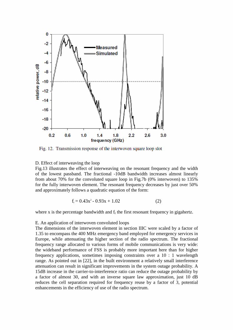
The element interweaving fraction was 0.85 (Fig.11a, b), with 0.0 representing the convoluted square loop in Fig.7b. The interweaving fraction is defined on Fig.11c by the location of the ends of the stubs between the extremes 0.0 and 1.0 on the diagram. Note that the gap between the stub ends belonging to the two interwoven elements is preserved. The transmission response (Fig.12) had peaks near 550MHz and 2050 MHz. In the simulations, the -10dB widths were 126% and 6% respectively. The measured insertion loss at the low band was about 1.8dB, but greater than 10dB at the narrow 2 GHz passband. Again, the transmission response simulated for plane wave illumination predicted well the behaviour of the FSS. There was a 45% reduction in the lower resonant frequency with respect the original convoluted square loop, while the bandwidth increased by a factor of 1.8. The figure of merit 1/p increased by 80% to 27 and L/1 halved, to 1.14. Note that this is now almost that of the open loop, singly polarised 5th generation Hilbert curve, while this closed interwoven convoluted structure is a bipolarised element.
D. Effect of interweaving the loop Fig.13 illustrates the effect of interweaving on the resonant frequency and the width of the lowest passband. The fractional -10dB bandwidth increases almost linearly from about 70% for the convoluted square loop in Fig.7b (0% interwoven) to 135% for the fully interwoven element. The resonant frequency decreases by just over 50% and approximately follows a quadratic equation of the form:
f r = 0.43x2 - 0.93x + 1.02 (2) where x is the percentage bandwidth and fr the first resonant frequency in gigahertz. E. An application of interwoven convoluted loops The dimensions of the interwoven element in section IIIC were scaled by a factor of 1.35 to encompass the 400 MHz emergency band employed for emergency services in Europe, while attenuating the higher section of the radio spectrum. The fractional frequency range allocated to various forms of mobile communications is very wide: the wideband performance of FSS is probably more important here than for higher frequency applications, sometimes imposing constraints over a 10 : 1 wavelength range. As pointed out in [22], in the built environment a relatively small interference attenuation can result in significant improvements in the system outage probability. A 15dB increase in the carrier-to-interference ratio can reduce the outage probability by a factor of almost 30, and with an inverse square law approximation, just 10 dB reduces the cell separation required for frequency reuse by a factor of 3, potential enhancements in the efficiency of use of the radio spectrum.
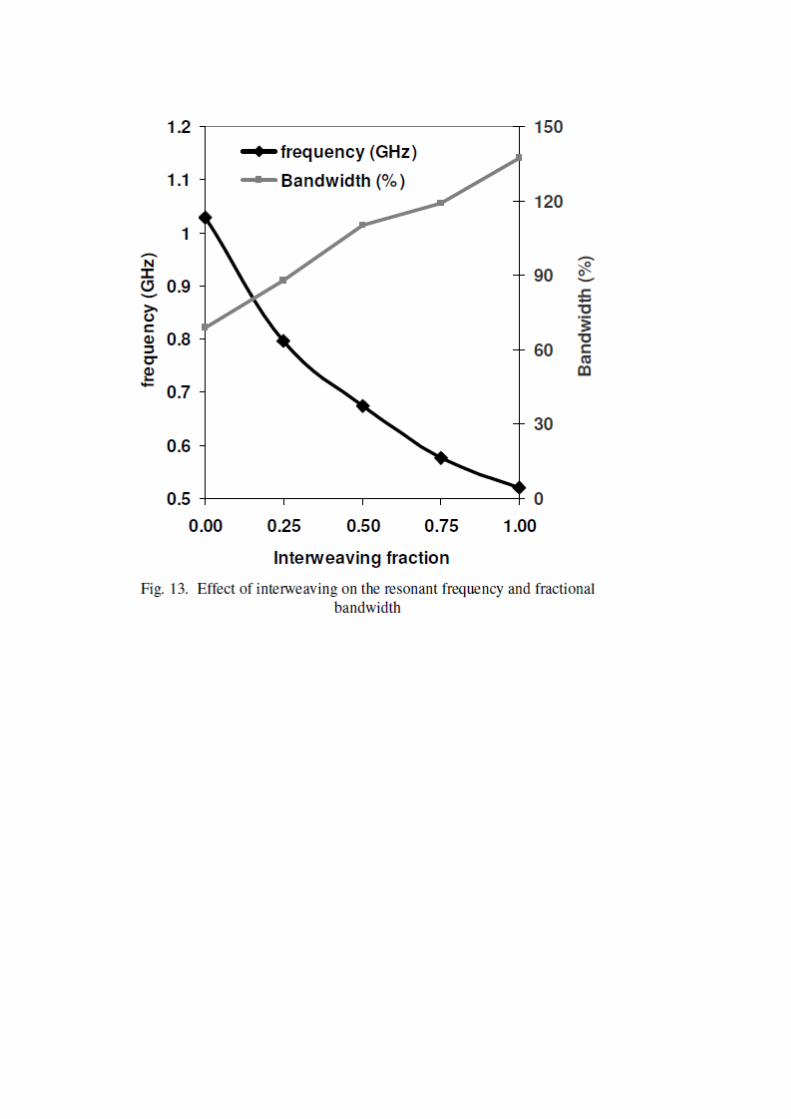
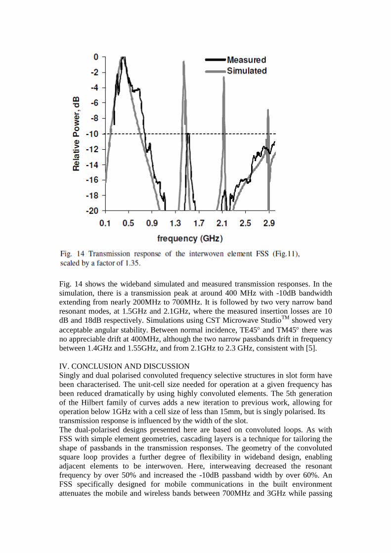
Fig. 14 shows the wideband simulated and measured transmission responses. In the simulation, there is a transmission peak at around 400 MHz with -10dB bandwidth extending from nearly 200MHz to 700MHz. It is followed by two very narrow band resonant modes, at 1.5GHz and 2.1GHz, where the measured insertion losses are 10 dB and 18dB respectively. Simulations using CST Microwave StudioTM showed very acceptable angular stability. Between normal incidence, TE45 and TM45 there was no appreciable drift at 400MHz, although the two narrow passbands drift in frequency between 1.4GHz and 1.55GHz, and from 2.1GHz to 2.3 GHz, consistent with [5]. IV. CONCLUSION AND DISCUSSION Singly and dual polarised convoluted frequency selective structures in slot form have been characterised. The unit-cell size needed for operation at a given frequency has been reduced dramatically by using highly convoluted elements. The 5th generation of the Hilbert family of curves adds a new iteration to previous work, allowing for operation below 1GHz with a cell size of less than 15mm, but is singly polarised. Its transmission response is influenced by the width of the slot. The dual-polarised designs presented here are based on convoluted loops. As with FSS with simple element geometries, cascading layers is a technique for tailoring the shape of passbands in the transmission responses. The geometry of the convoluted square loop provides a further degree of flexibility in wideband design, enabling adjacent elements to be interwoven. Here, interweaving decreased the resonant frequency by over 50% and increased the -10dB passband width by over 60%. An FSS specifically designed for mobile communications in the built environment attenuates the mobile and wireless bands between 700MHz and 3GHz while passing
the general mobile radio systems (GMRS) in the USA, and the personal mobile radio systems (PMR446) and the emergency services TETRA band in Europe. REFERENCES [1] M.Philippakis, C.Martel, D.Kemp, R.Allan, M.Clift, S.Massey, S.Appleton, W.Damerell, C.Burton, and E.A. Parker, “Application of FSS structures to selective control the propagation of signals into and out of buildings”, Ofcom ref AY4464A 2003 [2] M.Hook, K D Ward and C.Mias: “Project to demonstrate the ability of Frequency Selective Surface Structures to enhanced the spectral efficiency of radio systems when used within buildings”, Ofcom ref AY4462A 2003 [3] H.H. Sung, “Frequency Selective Wallpaper for Mitigation Indoor Wireless Interference”, PhD Thesis 2006, Auckland, New Zealand. [4] E.A. Parker, J.-B. Robertson, B. Sanz-Izquierdo and J.C. Batchelor, “Minimal Size FSS for Long Wavelength Operation”, IET Electronics Letters, vol. 44, Issue 6, pp. 394-395, March 2008 [5] E. A. Parker and A. N. A. El Sheikh, “Convoluted array elements and reduced size unit cells for frequency-selective surfaces,” IEE Proc. H: Microwaves, Antennas, and Propagation, vol. 138, pp. 19–22, Feb. 1991. [6] E.A. Parker and A.N.A. El Sheikh, “Convoluted dipole array elements”, IEE Electron. Lett., vol. 27, (4), pp. 322–323, 1991 [7] E.A. Parker, A.N.A. El Sheikh and A.C. Lima, “Convoluted frequency selective array elements derived from linear and crossed dipoles”, IEE Proc. H, vol. 40, (5), pp. 378–380, 1993 [8] A.D. Chuprin, E.A. Parker, J.C. Batchelor “Convoluted Double Square: Single Layer FSS with Close Band Spacings”, IET Electronics Letters, vol. 36, No.22, pp. 1830-1831, October March 2000 [9] H. Sagan, Space-Filling Curves. New York: Springer-Verlag, 1994. [10] K. J. Vinoy, K. A. Jose, V. K. Varadan, and V. V. Varadan, “Hilbert curve fractal antenna: A small resonant antenna for VHF/UHF applications,” Microw. Opt. Tech. Lett., vol. 29, no. 4, pp. 215–219, May 2001. [11] S. R. Best, “A comparison of the performance properties of the Hilbert curve fractal and meander line monopole antennas,” Microw. Opt. Tech. Lett., vol. 35, no. 4, pp. 258–262, Nov. 20, 2002. [12] J. Zhu, A. Hoorfar, and N. Engheta, “Bandwidth, cross polarization, and feed-point characteristics of matched Hilbert antennas,” IEEE Antennas Wireless Propagat. Lett., vol. 2, no. 1, pp. 2–5, 2003. [13] J. McVay, N. Engheta and A. Hoorfar, “High Impedance Metamaterial Surfaces Using Hilbert-Curve Inclusions”, IEEE Microwave and Wireless components letters, vol.14, no 3, March 2004 [14] S. Barbagallo, A. Monorchio and G. Manara, “Small periodicity FSS screens with enhanced bandwidth performance”, IET Electron. Lett., vol. 42, (7), pp. 382–384, 2006 [15] F. Huang, J.C. Batchelor and E.A. Parker, “Interwoven Convoluted Element Frequency Selective Surfaces with Wide Bandwidths”, IEE Electronics Letters, Vol.42, pp. 788-790, 14 July 2006 [16] B.A. Munk, Frequency selective surfaces: theory and design. John Wiley & Sons, USA, 2000, ch. 2.

[17] D. Sievenpiper, Lijun Zhang, R.F.J Broas, N.G. Alexopolous, E.Yablonovitch, “High-impedance electromagnetic surfaces with a forbidden frequency band”, IEEE Trans. Microw. Theory Tech., vol. 47,pp. 2059–2074, 1999 [18] S. Tse, B. Sanz-Izquierdo, J.C. Batchelor and R.J. Langley, “Reduced sized cells for high-impedance ground planes”, IET Electron. Lett., vol. 39, (24), pp. 1699–1701, 2003 [19] A. Lindenmayer, “Mathematical model for cellular interaction in development”, Journal of Theoretical Biology, Vol.18, pp. 280-315, 1968 [20] R.J. Langley, E.A. Parker “Double Square Frequency Selective Surfaces and their Equivalent Circuit”, IET Electron. Lett., Vol. 19, pp. 675-677, 1983 [21] P. Callaghan and E.A. Parker: ‘Loss- bandwidth product for frequency selective surfaces’, Electron. Lett., 1992, 28, (4), p. 365 [22] A.H. Wong, M.J. Neve, and K.W. Sowerby, “Performance analysis for indoor wireless systems employing directional antennas in the presence of external interference”, Proc. IEEE AP-S Int. Symp., 2005, 1A, Washington, D.C., USA, pp. 799–802