Embed Size (px)
Citation preview
Research ArticleStudy of Fast Transient Pressure Drop inVVER-1000 Nuclear Reactor Using Acoustic Phenomenon
Soroush Heidari Sangestani1 Mohammad Rahgoshay 1
Naser Vosoughi2 andMitra Athari Allaf1
1Department of Nuclear Engineering Science and Research Branch Islamic Azad University Tehran Iran2Department of Energy Engineering Faculty of Engineering Sharif University of Technology Tehran Iran
Correspondence should be addressed to Mohammad Rahgoshay mrahgoshaygmailcom
Received 10 June 2017 Revised 3 September 2017 Accepted 10 September 2017 Published 31 January 2018
Academic Editor Eugenijus Uspuras
Copyright copy 2018 Soroush Heidari Sangestani et al This is an open access article distributed under the Creative CommonsAttribution License which permits unrestricted use distribution and reproduction in any medium provided the original work isproperly cited
This article aims to simulate the sudden and fast pressure drop of VVER-1000 reactor core coolant regarding acoustic phenomenonIt is used to acquire a more accurate method in order to simulate the various accidents of reactor core Neutronic equationsshould be solved concurrently by means of DRAGON 4 and DONJON 4 coupling codes The results of the developed packageare compared with WIMSCITATION and final safety analysis report of Bushehr VVER-1000 reactor (FSAR) Afterwards timedependent thermal-hydraulic equations are answered by employing Single Heated Channel by Sectionalized Compressible Fluidmethod Then the obtained results were validated by the same transient simulation in a pressurized water reactor core Thenthermal-hydraulic and neutronic modules are coupled concurrently by use of producing group constants regarding the thermalfeedback effect Results were compared to the mentioned transient simulation in RELAP5 computer code which show that massflux drop is sensed at the end of channel in several milliseconds which causes heat flux drop too The thermal feedback resulted inproduction of some perturbations in the changes of these parametersThe achieved results for this very fast pressure drop representaccurate calculations of thermoneutronic parameters fast changes
1 Introduction
One of the most important aspects in design of differentsafety systems with sufficient preparation is simulation andanalysis of transient states in reactor core For these kinds ofanalysis basic equations in neutronic and thermal-hydraulicmodules have to be coupled Coupling of neutronic andthermal-hydraulic modules is different from each otherconsidering numerical solution methods and time and bodymeshing sizeThus written codes for different transient statesare mostly used for study of fuel and coolant temperaturechanges power peak level coolant pressure stability timeand other parameters Computer coding submitsmodels withdifferent degree of accuracy and validity Most codes arenot able to analyze coupled conditions of very fast transient(FT) states in very short time This deficiency is associatedwith neutronic and thermal-hydraulic calculations or both
Therefore designing a code which is capable of analyzing FTconditions is highly needed
One of the efficient ways in analyzing FT is using wave-formmethod Chan (1991) studied asymptotic waveform eva-luation in analysis of time-dependent calculations [1] Ooiet al (2003) studied the finite element method (FEM) inthermal analysis that usually produces a formulation in thespacetime domain However the sizes of the equations inFEM usually are large and thus the conventional algorithmsinvolve considerable computational time The conventionalmethods have to take a very small time step size to avoidundesirable numerically induced oscillations or numericalinstabilities Thus a new solution algorithm named theasymptotic waveform evaluation scheme was introduced bythem to solve transient problems [2] Liu et al (2006) studiedfast thermal simulation when power density increases byfast spectrum in frequency domain for computing steady
HindawiScience and Technology of Nuclear InstallationsVolume 2018 Article ID 7862847 11 pageshttpsdoiorg10115520187862847
2 Science and Technology of Nuclear Installations
state response It indicates that the resulting thermal analysisalgorithms lead to 10xndash100x speedup over the traditionalintegration-based transient analysis with small accuracy lossThe studied parameters minimum time order is 15ms [3]Ham and Bathe (2012) used FEM to solve time-dependenttwo-dimensional wave propagation problems [4] Ranaa etal (2014) presented the well condition asymptotic waveformevaluation to solve heat conduction problem in the fre-quency domainThemethod is presented for time-dependentproblems [5] In addition Ishii et al (2009) investigatedthe effect of acoustic phenomenon in steam dryer (in aBoiling water reactor) which indicates the process of pressurepulsations caused by hydroacoustic resonance propagationalong the steam dryer [6] Proskuryakov (2017) studied theeffect of acoustic vibrations in the nuclear power plant (NPP)coolant such asVVER-1000 reactor and created new scientificdirection ldquodiagnosis prognosis and prevention of vibration- acoustic resonances in the NPP equipmentrdquo shows thatthe developed methods can be used to predict and preventthe occurrence of vibration-acoustic resonances in the NPPequipment [7]
Various kinds of thermal-hydraulic and neutronic cal-culating models are put to use in transient calculatingcode development studies Reducing costs and runtime andachieving required accuracy are threemain purposes of themLeung et al (1981) studied acoustic impact techniques forincreasing the accuracy of FT states modeling in CODAcode [8] However regarding its very small meshing acousticmethods are time-consuming and are not used any more
In order to decrease complicated solving parameters inusing compressible fluid method geometry of every fuelassembly could be turned into a single heated channel (SHC)Four different methods are used to solve SHC transientequationsThey are channel integral (CI) singlemass velocity(SV) momentum integral (MI) and sectionalized compress-ible fluid (SC) SC model considers both sound impactand thermal expansion while the other three models onlyconsider thermal expansion [9] The SHC method is usedin costanza code (1967) in order to analyze the dynamics ofliquid cooled nuclear reactor [10] It is also used in DynCocode (2011) which is intended for complex neutron-physicand thermal-hydraulic dynamic calculation of the reactorcore in 3D hex-Z geometry DynCo code is designed tosimulate the dynamic behavior of the Russian 3000-MWtpressurized water reactor (PWR) [11] The coupling of CIand POWEX-K code (2011) simulates power excursion inreactor of Budapest University of Technology and EconomicsReactor [12] Hosseini et al (2015) developed a coupled 3Dneutronic with 1D thermal-hydraulic model in order to findreasonable power distribution Neutronic module includesthree-dimensional diffusion equation in two energy groupswhich was solved using analytic nodal method Thermal-hydraulic module contains the conservation equations solvedfor 1D axial homogeneous downward flow through channelusing SHC model (MI method) In conclusion Xenon satu-ration transient analysis of a research reactor core was carriedout [13]
The SHC compressible fluid method is one of the waysthat make it possible to use wave propagation method and
acoustic phenomenon Shapiro (1953) considered the deriva-tion and properties of the dynamics and thermodynamics ofcompressible fluid flow which is along with acoustic theory[14] Meyer (1961) investigated that several approximationscan be used to decouple themomentumand energy equationsto facilitate solution of the transient problem Additionallythe numerical solution of a transient problem would beparticularly simplified if the compressibility of the fluid couldbe ignored [15] Todreas and Kazimi (2001) investigated arapid increase in the heat flux without change in the appliedpressure drop in a PWR The SC approach for a 10 heatflux step increase in the PWR channel shows that because thepressure begins to rise at internal channel points a reductionin inlet flow rate and an accelerated exit flow rate occur [9]
The mechanism of compressible fluid method was pub-lished by Bar-Meir in 2007 [16] Khola and Pandey (2013)studied the numerical simulation of transients in two-phaseflow which is crucial to simulate accident-like conditions ofnuclear reactors for safety analysis In their work a code fornumerical computation of unsteady one-dimensional two-phase flowhas been developedThe governing equationswereobtained by the homogenous equilibrium mixture modeland were decoupled and approximated using the SC and MImodel [17]
Numerical considerations (ie the stability andor accu-racy) of the difference solution require that the time stepof integration be less than the time interval for sonic wavepropagation across the spatial grid points Comparedwith thetransport velocity the fluid sonic velocity is large It causeslimitation of the time step inmost numerical schemes to verysmall values Acoustic phenomenon is used in accommoda-tion of very short time and very small body meshing Thisaccommodation is determined by Courantrsquos criterion [8 20]
Δ119905 lt Δ119911(119862 + 119881119898) (1)
Δ119905 is time meshing period Δ119911 is body meshing distance119862 is sound velocity in coolant and 119881119898 = 119866119898119875119898 is themean transport velocity The fluid sonic velocity is largecomparing with the transport velocityTherefore limiting thetime step in most numerical schemes to very small valuesleads to a computationally expensive solution of this problemRegarding meshing size criterion pressure wave propagationmethodmostly requires long-term computations for numeralstability Therefore acoustic phenomenon features (despitethe high accuracy) are not usually considered by researchersHowever these features are very useful during core parametervital changes
FT pressure drop is a type of loss of coolant accident(LOCA) That is well known as the double ended guillotinebreak When double ended guillotine break occurs (maincoolant pipeline cold leg breaks at the reactor inlet) suddenlyreactor coolant pressure decreases with leak coolant flowrate of 45000Kgs [18] A pressure wave is also producedwhile the large break LOCA occurs which propagates acrossthe channel Therefore International Atomic Energy Agency(IAEA 2003) studied the before-break vital moment (leakbefore break) [21]
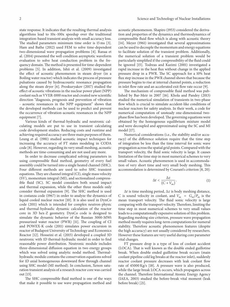
Science and Technology of Nuclear Installations 3
Z
12
3 45
6 7
89101112
13
141516
1718
1920
2122
232425
2627
28
De Dh
Node 180
Node 360
Node 1
Fuel assembly
Single heated channel16 of core
Figure 1 Fuel assembly conversion into SHC and meshing method toward 119911-axis
The coolant fast pressure drop accident can lead the fluidto become two-phased and thermoneutronic parameters tochange Gonzalez-Santalo and Lahey Jr (1972) investigatedthis matter by study of pressure drop transient in two-phasecondition [22]
Calculation program of VVER-1000 reactor core FT pres-sure drop by means of SCmethod and acoustic phenomenonwas developed in this investigation In order to use thementionedmethod every one of the 28 fuel assemblies shouldbe considered as one SHC Fuel assembly conversion intoSHC and meshing method toward 119911-axis are both shown inFigure 1
2 Materials and Methods
21 An Overview of Neutronic and Thermal-Hydraulic ModelA computational program for simulation of VVER-1000reactor core FT state of sudden pressure drop has beendeveloped in this study It includes the two thermal-hydraulicand neutronic basic models Group constants of the fuelassemblies and reflectors are produced by DRAGON 4code [23] DRAGON 4 is a lattice code developed to solveBoltzmann transport equation in two and three dimensionsto apply self-shielding effects and to compute few-groupmacroscopic cross sections and diffusion coefficients Thementioned program includes different models for simulationof fuel assembly behavior such as interpolation of micro-scopic cross sections resonance self-shielding calculationdifferent solvers for the Boltzmann transport equation withability to take into account leakage effects and calculation ofcondensed and homogenized parameters
In this study the integral transport equation is solvedby the SYBILT module self-shielding calculations are per-formedby the SHImodule bymeans of generalized Stammrsquolermethod and the CPO module is utilized for production
of equivalent fuel assembly parameters in consistent formatthat can be used in forgoing calculation After that time-dependentmultigroupneutron diffusion equations are solvedby DONJON 4 models [24] DONJON 4 is a multigroup dif-fusion solver A three-dimensional simulation is performedby ThomasndashRaviartndashSchneider method using The TRIVATmodule the group constants of fuel assembly calculated byDRAGON 4 are recovered using the CRE module and theFLUD module is to compute multiplication factor The FEMis utilized for discretization of equation Finally momentaryamount of power distribution is achieved in 16 of reactorcore across every fuel assembly
In thermal-hydraulic model conservation of mass andmomentum and energy dependent equations are solved byapplying considered transients and use of channel axialdivision in MATLAB software The channel is regarded asa typical coolant subchannel inside an assembly that onlyreceives coolant through its bottom inlet The fuel and cladheat transport equations are solved separately from coolantequations One-dimensional transient transport equations ofthe coolant with radial heat input from the clad surfacesare resolved The flow area is assumed axially uniform butpressure loss due to local area changes is still regarded Anyaxial position of flow area could be considered as control areain order to derive radially averaged coolant flow equationsMentioned equation is envisioned for SHC state and SCmethod of every 28 fuel assemblies (16 core) From the fourSHC different methods only SC model considers both soundimpact and thermal expansion while the other three modelsconsidering thermal expansion [9] Therefore it is able tostudy very FT states Some of the thermodynamic features ofwater are also regarded [25]
Several approximations can be used to decouple themomentum and energy equations to facilitate solution ofthis transient Additionally the numerical solution of the
4 Science and Technology of Nuclear Installations
discussed transient problem in this study is particularlysimplified following the work of Meyer [15] and specificapplications from Todreas and Kazimi [9] Therefore thelateral variations of properties in the flow channels can beneglected For this condition (2) (3) and (4) are directlyapplicable
120597120588119898120597119905 + 120597119866119898120597119911 = 0 (2)
120597119866119898120597119905 + 120597120597119911 (1198662119898120588119898 ) = minus120597119875
120597119911 minus 119891119866119898 100381610038161003816100381611986611989810038161003816100381610038162119863119890120588119898 minus 120588119898119892 (3)
120588119898 120597ℎ119898120597119905 + 119866119898 120597ℎ119898120597119911 = 11990210158401015840119875ℎ119860119911 + 120597119875120597119905
+ 119866119898120588119898 [120597119875120597119911 + 119891119866119898 100381610038161003816100381611986611989810038161003816100381610038162119863119890120588119898 ]
(4)
where ℎ119898 is enthalpy 119866119898 is mass flux 120588119898 is density 119860119911 isfluid level passing 119911 is of fuel assembly height 119905 is time 119891 isfriction coefficient 11990210158401015840 is heat flux 119863119890 is thermal-hydraulicdiameter 119888 is speed sound 119875 is pressure and 119875ℎ is heatedsurface Equations (2) (3) and (4) and appropriate constitu-tive relations provide the solutions for 119866119898(119911 119905) 119901(119911 119905) andℎ119898(119911 119905) for the initial and boundary conditions The heatflux 11990210158401015840(119911 119905) which is a DONJON output is specified asan input for the above equations The boundary conditionsfor solving the momentum and energy equations are to bespecified as 119875(0 119905) and ℎ119898(0 119905) at the inlet and 119875(119871 119905) at theoutlet Furthermore constitutive equations for 120588119898 and 119891 arerequired to complete definition of the problemThe equationof state for the density assumed differentiable with respect toℎ119898 and 119875 is specified as
120588119898 = 120588119898 (ℎ119898 119875) (5)
The friction factor can be specified as
119891 = 119891 (ℎ119898 119875 119866119898 11990210158401015840) (6)
In SC model numerical solution approach involves a setof difference equations representing the differential transportequations arranged to consider ℎ119898 119866119898 and 119875 and statevariables at multiple points along the channel Every oneof the 28 fuel assemblies is considered as a single heatedchannel The term sectionalized reflects the need to divide achannel into 360 segments to execute the numerical solutionregarding the height of every fuel assembly (36m) Using (5)we get
120597120588119898120597119905 = 120597120588119898120597ℎ11989810038161003816100381610038161003816100381610038161003816119901
120597ℎ119898120597119905 + 12059712058811989812059711990110038161003816100381610038161003816100381610038161003816ℎ119898
120597119875120597119905 = 119877ℎ 120597ℎ119898120597119905 + 119877119901 120597119875120597119905 (7)
where
119877ℎ = 120597120588119898120597ℎ11989810038161003816100381610038161003816100381610038161003816119901=const
119877119901 = 12059712058811989812059711990110038161003816100381610038161003816100381610038161003816ℎ119898=const
(8)
From (2) and (7) we get
119877ℎ 120597ℎ119898120597119905 + 119877119901 120597119875120597119905 + 120597119866119898120597119911 = 0 (9)
Equations (4) and (9) may be combined into two equationsby eliminating (120597119901120597119905) and (120597ℎ119898120597119905)
1205881198981198882120597119875120597119905 + 120588119898 120597119866119898120597119911 + 119877ℎ119866119898120588119898
120597119875120597119911 minus 119877ℎ119866119898 120597ℎ119898120597119911
= minus119877ℎ [11990210158401015840119875ℎ119860119911 + 119891119866211989811986611989821198631198901205882119898 ] 1205881198981198882
120597ℎ119898120597119905 + 120597119866119898120597119911 minus 119877119901119866119898120588119898
120597119875120597119911 + 119877119901119866119898 120597ℎ119898120597119911
= 119877119901 [11990210158401015840119875ℎ119860119911 + 119891119866211989811986611989821198631198901205882119898 ]
(10)
where we have defined 1198882 as1198882 = 120588119898120588119898119877119901+119877ℎ (11)
Equations (3) and (10) are partial differential equationsin 119875 119866119898 and ℎ119898 (ie the density does not appear asa differentiated variable) These equations were written inpointwise difference form (forward implicit method) andsolved in 119875 119866119898 and ℎ119898
Sound velocity is different in various spaces also the fluidis running in a specified direction with a specified speedFluid velocity is accordingly dependent on its other param-eters Regime pressure drop transient numerical consider-ations (ie the stability andor accuracy) of the differencesolution need that the time step of integration be less thanthe time interval for sonic wave propagation across the spatialgrid points that is (1) The time discretization that is usedin most codes varies from the semi-implicit scheme andmultistep schemes or the fully implicit discretization
Different codes have developed various methods forpredicting theses states CATHARE code [26] used criticalflow rate correlation method that way the geometry ofthe flow restriction is simplified and a coarse meshing isused TRACE [27] and RELAP5 [28] codes use characteristicvelocity that way the geometry of the flow restriction isalso simplified and a coarse meshing is used A soundcharacteristic velocity is set to zero and simplified equationsare used to predict flow evolution from upstream to the sonicsection The standard option in RELAP5 is a semi-implicitscheme Only those governing parameters are evaluated atnew time values which are needed to maintain stability andaccuracy of the method or to avoid Courant time step sizelimitations based on pressure waves CATHARE code [26] inanothermethod assumes that the flow fromupstream to sonicsection is precisely calculated by 2-fluid equations using avery finemeshing in the vicinity of the throat Such a methodis only possible with an implicit numerical scheme whichallows high velocity flow in small meshes without materialCourant limitation
Science and Technology of Nuclear Installations 5
Table 1 VVER-1000 geometry and operating conditions [18]
Operating condition ValueCore height in the working state (cm) 355Rod diameter (mm) 91Pitch (mm) 1275Fuel pellet material UO2Number of fuel rods in the fuel assembly 311Average linear heat rate (Wcm) 1667Coolant flow rate (m3h) 84800Inlet pressure (MPa) 16Outlet pressure (MPa) 1570Temperature at the inlet (∘C) 291
All these codes in which Courant criterion is not usedconsider different ways in order to decrease the time ofcalculations but still they do not have the accuracy ofthe codes using Courant criterion in time of critical flowconditions and very short times Therefore Courant criterionwas taken into account in the simulating codes of this studyTime mesh amount is obtained about 10 120583s considering Δ119911 =001 for solution stability and sound velocity of 900ms incoolant DRAGON and DONJONSHC developed code isregarded 1 120583s for more accuracy
22 Very FT Utility Analysis Very FT coolant pressure dropin VVER-1000 reactor core is explained in
119875in (119905) minus 119875out = 05 [119875in (0) minus 119875out] (1 + 119890minus400119905) (12)
It is highly mentioned that axial fluid motion is consid-ered steady in SC model which eliminates cross flow effect[9] By considering core symmetry one of the six parts ofcore is modeled which includes 28 fuel assembliesrsquo channelsTherefore despite the ones where core is assumed as onechannel radial accuracy of thermal-hydraulic and neutronicparameters is increased The impact of thermal feedback oncross sections is utilized for coupling the two mentionedmodules Eventually standard deviation of predicted resultsfor noted transient is estimated through accuracy evaluationof thermal-hydraulic and neutronic codes Some advantagesof SHC method by SC model are increasing the sufficientaccuracy in sudden transient state simulations and moreaccurate analysis of different transient states As mentionedbefore acoustic phenomenon increases the number of timemeshes and therefore the time of calculation becomes longerOn that account performing in FT states is the optimumcondition for using noted code (considering user demands)
23 Coupling Procedure Coupling algorithm of the twothermal-hydraulic and neutronic modules is as followsPrimarily every fuel assembly is modeled by DRAGON4 cell calculating code according to Table 1 This code isused (considering fresh fuel) in order to determine themacroscopic cross sections sequences and other neutronicparameters of all reactor fuel assemblies Instead of modelingthe whole core 28 fuel assemblies are modeled according
Table 2 PWR geometry and operating conditions [9]
Operating condition ValueChannel length (m) 366Rod diameter (mm) 970Pitch (mm) 1280Flow area for rod (mm2) 9000Equivalent diameter (mm) 1200Linear heat (kWm) 1750Mass flux (kgm2s) 4125Inlet pressure (MPa) 1550Outlet pressure (MPa) 1542Inlet enthalpy (kJkg) 13372
to core symmetry The next step is obtaining axial andradial power distributions by means of available triangulargeometry module of DONJON 4 and numeral solving bymeans of FEM also applying VVER-1000 reactor powerConsidering nonpoisonous fresh fuel reactor relative powerradial distribution is measured in order to evaluate the cal-culation algorithm authenticity of the two codesrsquo correlationand validated by comparing toWIMSCITATION [19] resultsand Bushehr VVER-1000 reactor FSAR [18]
In order to evaluate the authenticity of thermal-hydraulicmodule the mentioned transient is modeled in PWR corefuel assembly (conditions are noted in Table 2) and itsobtained results are compared to the Todreas and Kazimi [9]study results Core is composed of 28 fuel assemblies but onlyHot Fuel Assembly (HFA) coupling results are noted in thisassay Thermal-hydraulic properties of coolant fast pressuredrop accident in PWR core is simulated by SC method Theamounts of time periods which are caused by environmentalsound velocity limitations are also considered for currentsimulation After evaluating the authenticity of thermal-hydraulic module coupling results of the two neutronicand thermal-hydraulic modules of coolant fast pressuredrop accident in VVER-1000 reactor core could be studiedfor validation which is compared to RELAP5 (advanced-thermal-hydraulic code coupled with point kinetic modelto simulate neutronic behavior) [28] The thermal-hydraulicand neutronic coupling module algorithm is as followsthe procedure starts with obtaining the axial power profileof neutronic module in steady state The mentioned axialpower profile and other core dependent parameters (suddenpressure drop transient mass flux pressure temperaturechanges etc) are the entering data of thermal-hydraulicmodule program Axial thermal changes affect the nuclearcross sections and the new power profile in neutronicmoduleis produced Then the new axial power profile is applied onthermal-hydraulicmodule It is continued until the differencebetween axial thermal changes in every time step is less thana specified amount of convergence criteria Neutronic andthermal-hydraulic coupling calculations algorithm are shownin Figure 2
As a result of time period selection limitations (short timeperiods) which leads to increase in the number of nodesthe rise in parameter numbers of defined study case and
6 Science and Technology of Nuclear Installations
Sequence production of group constants
Solving thermal-hydraulic equation basedon every fuel assembly
Is the convergence criterion satisfactory
Is the place period finished
Is the period finished
End
Solving neutronic equation and obtainingpower based on every fuel assembly
No
No
No
Calculations initializing in Δt time steps
Calculation initializing in Δx place step
Yes
Yes
Yes
Figure 2 Neutronic and thermal-hydraulic coupling calculation algorithm
complicated equations or scales should not be consideredTherefore program solving time is lowered
3 Results and Discussion
31 Results of Neutronic Calculations Relative radial powerdistribution in 16 of VVER-1000 reactor core is shownin Table 3 Power Peaking Factor is compared to WIMSCITATION [19] and BushehrVVER-1000 reactor FSAR value[18] as observed Obtained results show an unremarkablecalculation error for the two neutronic coupled codes
The maximum coupling calculation errors of DRAGON4DONJON 4 is 28 while it is 564 inWIMSCITATION[19] codes The obtained results of DRAGON 4 andDONJON 4 codes coupling shows higher accuracy thanWIMSCITATION codes as observed Then relative axialpower distribution in 16 of VVER-1000 reactor core isanalyzed which is shown in Figure 3 As observed the peakof relative axial power distribution (in beginning of cycle)occurs lower than the middle height of core Relative axialpower distribution is more coordinated to Bushehr VVER-1000 reactor FSAR [18] when using DRAGON 4DONJON 4coupling rather than WIMSCITATION coupling [19]
32 Results of Thermal-Hydraulic Calculations After thedefinedmodel is validated thermal-hydraulic module prepa-ration is started based on SHC by SC method In order toevaluate the authenticity of newly made module coolant fastpressure drop accident in PWR core fuel assembly is simu-lated by SCmethod (PWR core features are noted in Table 2)This simulation also considers different amounts of time peri-ods which are caused by environmental limitations of sound
16
14
12
10
08
06
04
02
00
Rela
tive a
xial
pow
er
0 10 20 30 40 50 60 70 80 90 100
Coordinate from the core bottom ()
FSAR [18]
WIMS amp CITATION [19]DRAGONDONJON
Figure 3 Relative axial power distribution in 16 of VVER-1000reactor core
velocity Severe decreases in entrance pressure (also neutronicchanges stability) cause mass flux reduction which is dis-tributed in the channel during spent time [9 29]The outputsof thermal-hydraulic program which are normalized massflux changes during axial side of the channel are shown inFigure 4 Sound velocity is calculated 900ms causing chan-nel transient state to last for 41ms The mass flux fast reduc-tion of 119905 lt 41ms would not reach the end of the channeltherefore upper sides will not be affected by pressure wave
Science and Technology of Nuclear Installations 7
Table 3 Relative power radial distribution in 16 of VVER-1000 reactor core
Fuel assembly number Power peaking factor(FSAR) [18]
Power peaking factor(DRAGON 4DONJON 4)
Power peaking factor(WIMSCITATION) [19]
1 101 102 0992 080 079 0783 102 101 1004 075 075 0725 086 085 0836 092 089 0907 116 117 1188 092 093 0909 078 078 07610 087 088 08411 086 085 08412 124 122 12413 096 097 09814 078 077 07615 103 104 10216 089 088 08717 111 110 11118 118 117 12419 087 086 08420 089 087 08721 129 127 13122 124 125 13123 086 085 08424 111 109 11125 124 123 13126 124 122 12427 118 117 12428 096 096 098
For 119905 gt 41ms the reflected pressure wave affects themass flux It happens because of stable outer pressure theorywhich means when opposite pole wave (with similar ampli-tude) moves in opposite direction the diluted entrance waveis reflected like compressed wave in outer border Pressureprofile in 119905 asymp 5ms and longer times shows the effect of reflec-tion wave progress all the way from exit to entrance In thatshort amount of time average mass flux rate only decreasesfrom 1 to 098 Figure 4 shows the results of program per-formance and has an acceptable accommodation with refer-ence diagram [9] as observed
The written program accuracy in neutronic states iscompared to Bushehr VVER-1000 reactor FSAR data [18]Also it is compared to PWR data [9] in thermal-hydraulicstates After the authenticity evaluation of neutronic andthermal-hydraulic modules correlated FT states and changesof various parameters during time are studied
33 Results of Coupling Calculations Changing diagrams ofthermal-hydraulic parameters by using sound effect in pres-sure propagation for very FT coolant pressure drop inVVER-1000 reactor HFA are being studied Pressure drop causesthe mass flux reduction therefore temperature increases andpower drops in every node The transfer of each nodersquos ther-mal data to DRAGON4module leads to the decrease of crosssection moderation Mentioned data and axial power profileare used as DONJON 4 module entrance Finally loweredpower distribution and pressure drop transient are applied asthermal-hydraulic module and thermal distribution of everyone of 360 nodes is obtained again The process continuesuntil the convergence criteria of each node thermal differ-ence are available Considering the central pressure of eachnode and reactor core pressure changes which is 03MPaalterations of pressure per time for the first node is shown inFigure 5 that reveals pressure drop of 00012MPa per 1ms
8 Science and Technology of Nuclear Installations
2ms
4ms
5ms
6ms8ms
9ms
Thermal-hydraulic moduleReference [9]
100
099
098
0970 02 04 06 08 10
Normalized axial position (zl)
Nor
mal
ized
flow
rate
Gm
(zt
)G
m(00
)
Figure 4 Short-term response of the PWR inlet pressure transientusing the SC model
16000
15998
15996
15994
15992
15990
15988
Pres
sure
(Pa )
lowast10
7
Time (s) lowast 10minus50 10 20 30 40 50 60 70 80 90 100
Figure 5 Alterations of pressure per time for the first node
Figure 6 shows mass flux changes during fuel assemblyin three different times Increasing the time from 10 120583s to2ms causes a mass flux drop up to more than half of thefuel assembly Mass flux drop in 10120583s which is 035 Kgm2soccurs up to the beginning of fuel assembly However thesechanges are not sensed by the upper nodes After 1msmass flux drop arrives at the middle of fuel assembly whichincreases from 035 Kgm2s to 12 Kgm2s for the first nodeand decreases to 25Kgm2s after 2ms The channel transienttime of sonic wave is about 4ms The rapid decrease of themass flux has not yet reached the end of the channel in thisperiod of time that means the upstream region is not yetaffected by the pressure wave
Mass flux changes in 5ms indicate the wave reflux fromend of the channel From now on for a few millisecondsthe reversible wave causes more mass flux drop in the endof channel than the beginning of it Mass flux changes in 5and 9ms which are calculated by RELAP5 [28] are shown inthe diagram RELAP5 does not sense pressure drop transientin times before 42ms and therefore it has some delay
3215
3210
3205
3200
3195
3190
3185
3180
3175
3170
RELAP5RELAP5
0 01 02 03 04 05 06 07 08 09
10 s1ms2ms5ms5ms9ms
Relative Lenght (ZL)
Mas
s flux
(Kg
m s2
)
DONJON amp DRAGONSHCDONJON amp DRAGONSHCDONJON amp DRAGONSHCDONJON amp DRAGONSHC
Figure 6 Mass flux changes during fuel assembly in different threetimes
comparing to DRAGON 4 and DONJON 4SHC codes andlesser time periods are not possible to be compared
The observed difference between DRAGON 4 and DON-JON4SHCdiagram (in 5ms) andRELAP5diagram (in 5ms)is because of the difference between neutronic and thermal-hydraulic modules accuracy Also the effects of thermal feed-back cause perturbation inmass flux alterations inDRAGON4 and DONJON 4SHC code RELAP5 [28] results only showthe average mass flux drop caused by pressure drop Averagemass flux changes with steady slope have four reasons
(1) Driving force drop caused by inlet pressure drop thatreduces the channel average mass flux
(2) The fluid thermal expansion due to heating whichcauses a small slope change that is 119866in becomes lessthan 119866out
(3) The fluids being considered uncompressible (ie120597120588120597119875 = 0)(4) Weak neutronic model and not using sufficient time
meshes sizes for the mentioned transient
The obtained results from mass flux changes simulationin primary middle and ending points of relative length offuel assembly in 9ms in DRAGON 4 and DONJON 4SHCand RELAP5 code are shown in Figure 7 Mass flux inthe first node initially faces a severe drop which continuesfor 2ms When this drop becomes more visible in uppernodes diagrams slope turns more gradual along with averagedrop of 0068 (Kgm2s) Mass flux in central point of fuelassembly starts dropping after whereabouts 12ms Howeversevere drop for ending points occurs after 4ms The profilesat 119905 asymp 4ms and more show the effect of the reflectedwave progressing toward the channel exit from the inletDuring this short period of time themass flux only decreases
Science and Technology of Nuclear Installations 9
3220
3210
3200
3190
3180
3170
3160
3150
Mas
s flux
(Kg
m2s)
Node 1Node 180Node 360Node 1Node 180Node 360
RELAP 5RELAP 5RELAP 5
Time (s) lowast 10minus30 1 2 3 4 5 6 7 8 9
DONJON amp DRAGONSHCDONJON amp DRAGONSHCDONJON amp DRAGONSHC
Figure 7 Mass flux changes during fuel assembly in different threenodes
Node 1Node 180Node 360
1200
1000
800
600
400
200
Flux
(Kw
m2)
00
30 60 90 120 150 180 210 240 270 300
Time (s) lowast 10minus5
Figure 8 HFA heat flux changing per time for beginning middleand ending nodes of fuel assembly
60Kgm2s The net mass flux is the superposition of theforward wave and the reflected wave
RELAP5 results show mass flux profile changes withsteady slope in primary middle and ending points and doesnot present adequate description of the passing pressurewave
HFA heat flux changing per time for beginning middleand ending nodes of fuel assembly in ldquo0ndash3msrdquo period oftime is shown in Figure 8 The heat flux of first node dropswhereabouts 40KWm2 in that amount of time Howevermass flux of fuel assembly middle node drops whereabouts30KWm2 in 17ms It also occurs after 23ms for endingnode Temperature changes per time for the first node areshown in Figure 9 which face drop of 001∘C in 006ms after
290900
290898
290896
290894
290892
290890
290888
Tem
pera
ture
(∘C)
Time (s) lowast 10minus50 10 20 30 40 50 60 70 80 90
Figure 9 Temperature changes per time for the first node
the beginning of the accident Mentioned drop is inevitablebased on constant axial power decrease
4 Conclusions
Simulation of VVER-1000 reactor core FT pressure dropby using acoustic phenomenon was studied in this articleCoupling of the two DRAGON 4 and DONJON 4 neutronicmodules along with thermal-hydraulic module by means ofSC method was utilized in this simulation It is the first timethat neutronic and thermal-hydraulic modules are externallycoupled assuming that the coolant fluid is compressible inorder to obtain the best simulation for this transient
In this transient at the channel inlet the mass flux beginsto decrease because of the pressure reduction it was observedin calculations that a perturbation was produced and prop-agates into the channel as time elapses After pressure wavesarrive at the end of the channel reflected pressurewaves affectthe mass flux profile for short timeThe incoming rarefactionwave will be reflected as a compression wave due to theassumption of constant outlet pressure at the exit boundaryTherefore a wave travels in the opposite direction with thesame amplitude but opposite sign The reverse wave causesmore mass flux drop in upper nodes and as time passes itdecreases the difference between upper nodes mass flux dropand the ones in beginning of the channelThus it is concludedthat in such transients mass flux drop rate does not followstable conditions
This transient (double ended guillotine break) is very fastand therefore DRAGON 4 and DONJON 4 codes are usedin neutronicmodule (comparing toWIMSCITATION) con-sidering their high speed and accuracy in analyzing the prob-lem Also SCmethod is utilized in thermal-hydraulic modulefor solutions of conservation equations by forward implicitmethod and Courantrsquos criterion in a SHC Thus the veryshort time step (120583s grades) was used in analyzing transientThe neutronic module was validated by WIMSCITATIONand FSAR Thermal-hydraulic module was also validated bysimulation of a PWR (comparing to Todreas and Kazimi [9]simulated one) Finally the simulated pressure drop transient(by DRAGON and DONJONSHC code) was also simulatedin RELAP5 code and results were compared RELAP5 code
10 Science and Technology of Nuclear Installations
was not capable of sensing the mentioned transient in timesbefore 42ms and unlike DRAGON and DONJONSHCcode coolant fluid is assumed uncompressible in it Sochanges of density per pressure is considered zero Of coursethis assumption is highly reasonable for classes of coretransients that do not have the problem of losing a greatamount of coolant Therefore mass flux changes slope isalmost steady along the channel and mass flux changes areonly dependent on pressure changes in channel inlet andoutlet Thus it became completely obvious that despite thefact that RELAP5 code uses ldquonearly implicitrdquo scheme basedon a ldquofractional steprdquo approach for providing a sufficientdegree of implicitness to eliminate the material Courant-typestability limit but it does not give an adequate description ofthe mentioned studied transient
The obtained results fromDRAGON andDONJONSHCfor the times that a great volume of coolant is lost in ashort time assuming coolant fluid is compressible are highlyacceptable and they show its ability to effectively and accu-rately calculate the fast transient On account of that theresults are not desirable if the sonic effect in coolant is notregarded
Abbreviations
FT Fast transientFEM Finite element methodPWR Pressurized water reactorCI Channel integralSV Single mass velocityMI Momentum integralSC Sectionalized compressible fluidNPP Nuclear power plantFSAR Final safety analysis reportLOCA Loss of coolant accidentSHC Single heated channelHFA Hot fuel assemblyms Millisecond120583s MicrosecondIAEA International Atomic Energy Agency
Conflicts of Interest
All authors have no conflicts of interest to declare
Acknowledgments
This study was performed as part of long-term researchinto nuclear safety supported by the Nuclear EngineeringDepartment of Science and Research Branch Islamic AzadUniversity The valuable researches into various accidents ofVVER-1000 reactor led us into performing this study
References
[1] P K Chan ldquoComments on ldquoAsymptotic Waveform Evaluationfor Timing Analysisrdquo1rdquo IEEE Transactions on Computer-AidedDesign of Integrated Circuits and Systems vol 10 no 8 pp 1078-1079 1991
[2] C Ooi K Seetharamu Z Alauddin G Quadir K Sim andT Goh ldquoFast transient solutions for heat transfer [FEM]rdquo inProceedings of the IEEE TENCON 2003 Conference on Conver-gent Technologies for the Asia-Pacific Region pp 469ndash473Bangalore India 2003
[3] P Liu H Li L Jin W Wu S X-D Tan and J Yang ldquoFastthermal simulation for runtime temperature tracking andman-agementrdquo IEEE Transactions on Computer-Aided Design of Inte-grated Circuits and Systems vol 25 no 12 pp 2882ndash2892 2006
[4] S Ham and K Bathe ldquoA finite element method enriched forwave propagation problemsrdquo Computers amp Structures vol 94-95 pp 1ndash12 2012
[5] M S Ranaa K Jeevanb R Harikrishnanc and A W RezadldquoA well-condition asymptotic waveform evaluation method forheat conduction problemsrdquo Advanced Materials Research vol845 pp 209ndash215 2014
[6] K Ishii T Nagayoshi S Takahashi Y Wada and N TanikawaldquoAdvanced simulation technologies for nuclear power plantsrdquoHitachi Review vol 58 no 2 pp 94ndash101 2009
[7] K N Proskuryakov ldquoScientific Basis forModeling and Calcula-tion ofAcousticVibrations in theNuclear Power PlantCoolantrdquoRecent Advances in Petrochemical Science vol 2 no 1 2017
[8] J C M Leung K A Gallivan and R E Henry Critical HeatFlux PredictionsDuring BlowdownTransient ArgonneNationalLaboratory Argonne IL60439 USA 1981
[9] N E Todreas and M S Kazimi ldquoThermal Hydraulic Funda-mentalsrdquoMassachusetts Institute of Technology 1990
[10] G Forti and E Vincenti ldquoThe codes costanza for the dynamicsof liquid cooled nuclear reactor joint nuclear research centerIspra stablishment - Italyrdquo Reactor Physics Department ReactorTeory and Analysis 1967
[11] AV Levchenko IN Leonov and SVKovalchuk ldquoVerificationof the three dimensional dynamic DYNCO code on the basisof international test cases for pressurized water reactorsrdquoSimulation Systems Ltd 2011
[12] S M Khaleda and F Al Mutairic ldquoA Numerical Technique ForSolving Coupled Thermal hydraulic and Multi-Energy GroupNeutron Diffusion Equationsrdquo A Department of Studies andBasic Sciences Community College University of Tabuk SaudiArabia 2011
[13] M Hosseini H Khalafi and S Khakshournia ldquoTwo groupthree dimensional diffusion theory coupled with single heatedchannel model A study based on xenon transient simulation ofTehran research reactorrdquo Progress in Nuclear Energy vol 85 pp108ndash120 2015
[14] A H ShapiroTheDynamics andThermodynamics of Compress-ible Fluid Flow vol 1 Ronald Press Co New York NY USA1953
[15] J E Meyer ldquoHydrodynamicmodels for the treatment of reactorthermal transientsrdquoNuclear Science and Engineering vol 10 pp269ndash277 1961
[16] G Bar-Meir ldquoFundamentals of Compressible Fluid Mechanics2007rdquo Version 0442 aka 0441j May 21 Minneapolis MN55414-2411
[17] N Khola and M Pandey ldquoNumerical computation of one-dimensional unsteady two-phase flow using hem model andIAPWS IF-97 equations of staterdquo in Proceedings of the 2013 21stInternational Conference on Nuclear Engineering ICONE 2013China August 2013
[18] AEOI Reactor Final Safety Analysis Report VVER-1000 Bush-ehr Chapter 4 Atomic Energy Organization of Iran 2005
Science and Technology of Nuclear Installations 11
[19] A H Fadaei and S Setayeshi ldquoControl rod worth calculationfor VVER-1000 nuclear reactor using WIMS and CITATIONcodesrdquo Progress in Nuclear Energy vol 51 no 1 pp 184ndash1912009
[20] J Plesek R Kolman and D Gabriel ldquoEstimation of The Cri-tical Time Step for Explicit Integrationrdquo in Proceedings of the18th International Conference Engineering Mechanics SvratkaCzech Republic 2012
[21] IAEA-TECDOC-1361 Assessment and management of ageingof major nuclear power plant components important to safetyPrimary piping in PWRs Scientific and Technical PublicationsVienna Austria 2003
[22] J M Gonzalez-Santalo and R T Lahey Jr An Exact Solution ofFlow Decay Transients in Two-Phase Systems by The Method ofCharacteristicsTheAmerican Society ofMechanical EngineersNew York NY USA 1972
[23] G Marleau A Hebert and R A Roy ldquoA user guide forDRAGON Version 4rdquo Institute of Genius Nuclear Departmentof Genius Mechanical School Polytechnic of Montreal 2011
[24] D Sekki A Hebert and R Chambon ldquoA User Guide forDonjon 4 Version 4rdquo Institute of Genius Nuclear Department ofGenius Mechanical School Polytechnic of Montreal 2011
[25] W Wagner and H-J Kretzschmar International Steam TablesFaculty of Mechanical Engineering Chair of Thermodynamics2nd edition 2007
[26] G Lavialle ldquoThe CATHARE 2 V25 code Main featuresCATHARE-NEPTUNE International Seminarrdquo Grenoble May2004
[27] TRACE-V50TheoryManual 2007 TRACEV50UserManual2007 TRACE V50 Assessment Manual 2007
[28] RELAP5SCDAPMOD32 Code Manuals A Computer Codefor Best-Estimate Transient Simulation of Light Water ReactorCoolant SystemsDuring SevereAccidents Prepared for theUSNuclear Regulatory Commission Idaho National Engineeringand Environmental Laboratory NUREGCR-6150 1997
[29] M Rahgoshay Encyclopedia of Advanced Subjects on NuclearHeat Transfer vol 1 Chapter 3 Islamic AzadUniversity CentralTehran Branch Iran 2016 ISBN 978-964-10-4389-8
Hindawiwwwhindawicom Volume 2018
Nuclear InstallationsScience and Technology of
TribologyAdvances in
Hindawiwwwhindawicom Volume 2018
International Journal of
AerospaceEngineeringHindawiwwwhindawicom Volume 2018
OpticsInternational Journal of
Hindawiwwwhindawicom Volume 2018
Antennas andPropagation
International Journal of
Hindawiwwwhindawicom Volume 2018
Power ElectronicsHindawiwwwhindawicom Volume 2018
Advances in
CombustionJournal of
Hindawiwwwhindawicom Volume 2018
Journal of
Hindawiwwwhindawicom Volume 2018
Renewable Energy
Acoustics and VibrationAdvances in
Hindawiwwwhindawicom Volume 2018
EnergyJournal of
Hindawiwwwhindawicom Volume 2018
Hindawiwwwhindawicom
Journal ofEngineeringVolume 2018
Hindawiwwwhindawicom Volume 2018
International Journal ofInternational Journal ofPhotoenergy
Hindawiwwwhindawicom Volume 2018
Solar EnergyJournal of
Hindawiwwwhindawicom Volume 2018
Shock and Vibration
Hindawiwwwhindawicom Volume 2018
Advances in Condensed Matter Physics
International Journal of
RotatingMachinery
Hindawiwwwhindawicom Volume 2018
Hindawiwwwhindawicom Volume 2018
High Energy PhysicsAdvances in
Hindawiwwwhindawicom Volume 2018
Active and Passive Electronic Components
Hindawi Publishing Corporation httpwwwhindawicom Volume 2013Hindawiwwwhindawicom
The Scientific World Journal
Volume 2018
Submit your manuscripts atwwwhindawicom
2 Science and Technology of Nuclear Installations
state response It indicates that the resulting thermal analysisalgorithms lead to 10xndash100x speedup over the traditionalintegration-based transient analysis with small accuracy lossThe studied parameters minimum time order is 15ms [3]Ham and Bathe (2012) used FEM to solve time-dependenttwo-dimensional wave propagation problems [4] Ranaa etal (2014) presented the well condition asymptotic waveformevaluation to solve heat conduction problem in the fre-quency domainThemethod is presented for time-dependentproblems [5] In addition Ishii et al (2009) investigatedthe effect of acoustic phenomenon in steam dryer (in aBoiling water reactor) which indicates the process of pressurepulsations caused by hydroacoustic resonance propagationalong the steam dryer [6] Proskuryakov (2017) studied theeffect of acoustic vibrations in the nuclear power plant (NPP)coolant such asVVER-1000 reactor and created new scientificdirection ldquodiagnosis prognosis and prevention of vibration- acoustic resonances in the NPP equipmentrdquo shows thatthe developed methods can be used to predict and preventthe occurrence of vibration-acoustic resonances in the NPPequipment [7]
Various kinds of thermal-hydraulic and neutronic cal-culating models are put to use in transient calculatingcode development studies Reducing costs and runtime andachieving required accuracy are threemain purposes of themLeung et al (1981) studied acoustic impact techniques forincreasing the accuracy of FT states modeling in CODAcode [8] However regarding its very small meshing acousticmethods are time-consuming and are not used any more
In order to decrease complicated solving parameters inusing compressible fluid method geometry of every fuelassembly could be turned into a single heated channel (SHC)Four different methods are used to solve SHC transientequationsThey are channel integral (CI) singlemass velocity(SV) momentum integral (MI) and sectionalized compress-ible fluid (SC) SC model considers both sound impactand thermal expansion while the other three models onlyconsider thermal expansion [9] The SHC method is usedin costanza code (1967) in order to analyze the dynamics ofliquid cooled nuclear reactor [10] It is also used in DynCocode (2011) which is intended for complex neutron-physicand thermal-hydraulic dynamic calculation of the reactorcore in 3D hex-Z geometry DynCo code is designed tosimulate the dynamic behavior of the Russian 3000-MWtpressurized water reactor (PWR) [11] The coupling of CIand POWEX-K code (2011) simulates power excursion inreactor of Budapest University of Technology and EconomicsReactor [12] Hosseini et al (2015) developed a coupled 3Dneutronic with 1D thermal-hydraulic model in order to findreasonable power distribution Neutronic module includesthree-dimensional diffusion equation in two energy groupswhich was solved using analytic nodal method Thermal-hydraulic module contains the conservation equations solvedfor 1D axial homogeneous downward flow through channelusing SHC model (MI method) In conclusion Xenon satu-ration transient analysis of a research reactor core was carriedout [13]
The SHC compressible fluid method is one of the waysthat make it possible to use wave propagation method and
acoustic phenomenon Shapiro (1953) considered the deriva-tion and properties of the dynamics and thermodynamics ofcompressible fluid flow which is along with acoustic theory[14] Meyer (1961) investigated that several approximationscan be used to decouple themomentumand energy equationsto facilitate solution of the transient problem Additionallythe numerical solution of a transient problem would beparticularly simplified if the compressibility of the fluid couldbe ignored [15] Todreas and Kazimi (2001) investigated arapid increase in the heat flux without change in the appliedpressure drop in a PWR The SC approach for a 10 heatflux step increase in the PWR channel shows that because thepressure begins to rise at internal channel points a reductionin inlet flow rate and an accelerated exit flow rate occur [9]
The mechanism of compressible fluid method was pub-lished by Bar-Meir in 2007 [16] Khola and Pandey (2013)studied the numerical simulation of transients in two-phaseflow which is crucial to simulate accident-like conditions ofnuclear reactors for safety analysis In their work a code fornumerical computation of unsteady one-dimensional two-phase flowhas been developedThe governing equationswereobtained by the homogenous equilibrium mixture modeland were decoupled and approximated using the SC and MImodel [17]
Numerical considerations (ie the stability andor accu-racy) of the difference solution require that the time stepof integration be less than the time interval for sonic wavepropagation across the spatial grid points Comparedwith thetransport velocity the fluid sonic velocity is large It causeslimitation of the time step inmost numerical schemes to verysmall values Acoustic phenomenon is used in accommoda-tion of very short time and very small body meshing Thisaccommodation is determined by Courantrsquos criterion [8 20]
Δ119905 lt Δ119911(119862 + 119881119898) (1)
Δ119905 is time meshing period Δ119911 is body meshing distance119862 is sound velocity in coolant and 119881119898 = 119866119898119875119898 is themean transport velocity The fluid sonic velocity is largecomparing with the transport velocityTherefore limiting thetime step in most numerical schemes to very small valuesleads to a computationally expensive solution of this problemRegarding meshing size criterion pressure wave propagationmethodmostly requires long-term computations for numeralstability Therefore acoustic phenomenon features (despitethe high accuracy) are not usually considered by researchersHowever these features are very useful during core parametervital changes
FT pressure drop is a type of loss of coolant accident(LOCA) That is well known as the double ended guillotinebreak When double ended guillotine break occurs (maincoolant pipeline cold leg breaks at the reactor inlet) suddenlyreactor coolant pressure decreases with leak coolant flowrate of 45000Kgs [18] A pressure wave is also producedwhile the large break LOCA occurs which propagates acrossthe channel Therefore International Atomic Energy Agency(IAEA 2003) studied the before-break vital moment (leakbefore break) [21]
Science and Technology of Nuclear Installations 3
Z
12
3 45
6 7
89101112
13
141516
1718
1920
2122
232425
2627
28
De Dh
Node 180
Node 360
Node 1
Fuel assembly
Single heated channel16 of core
Figure 1 Fuel assembly conversion into SHC and meshing method toward 119911-axis
The coolant fast pressure drop accident can lead the fluidto become two-phased and thermoneutronic parameters tochange Gonzalez-Santalo and Lahey Jr (1972) investigatedthis matter by study of pressure drop transient in two-phasecondition [22]
Calculation program of VVER-1000 reactor core FT pres-sure drop by means of SCmethod and acoustic phenomenonwas developed in this investigation In order to use thementionedmethod every one of the 28 fuel assemblies shouldbe considered as one SHC Fuel assembly conversion intoSHC and meshing method toward 119911-axis are both shown inFigure 1
2 Materials and Methods
21 An Overview of Neutronic and Thermal-Hydraulic ModelA computational program for simulation of VVER-1000reactor core FT state of sudden pressure drop has beendeveloped in this study It includes the two thermal-hydraulicand neutronic basic models Group constants of the fuelassemblies and reflectors are produced by DRAGON 4code [23] DRAGON 4 is a lattice code developed to solveBoltzmann transport equation in two and three dimensionsto apply self-shielding effects and to compute few-groupmacroscopic cross sections and diffusion coefficients Thementioned program includes different models for simulationof fuel assembly behavior such as interpolation of micro-scopic cross sections resonance self-shielding calculationdifferent solvers for the Boltzmann transport equation withability to take into account leakage effects and calculation ofcondensed and homogenized parameters
In this study the integral transport equation is solvedby the SYBILT module self-shielding calculations are per-formedby the SHImodule bymeans of generalized Stammrsquolermethod and the CPO module is utilized for production
of equivalent fuel assembly parameters in consistent formatthat can be used in forgoing calculation After that time-dependentmultigroupneutron diffusion equations are solvedby DONJON 4 models [24] DONJON 4 is a multigroup dif-fusion solver A three-dimensional simulation is performedby ThomasndashRaviartndashSchneider method using The TRIVATmodule the group constants of fuel assembly calculated byDRAGON 4 are recovered using the CRE module and theFLUD module is to compute multiplication factor The FEMis utilized for discretization of equation Finally momentaryamount of power distribution is achieved in 16 of reactorcore across every fuel assembly
In thermal-hydraulic model conservation of mass andmomentum and energy dependent equations are solved byapplying considered transients and use of channel axialdivision in MATLAB software The channel is regarded asa typical coolant subchannel inside an assembly that onlyreceives coolant through its bottom inlet The fuel and cladheat transport equations are solved separately from coolantequations One-dimensional transient transport equations ofthe coolant with radial heat input from the clad surfacesare resolved The flow area is assumed axially uniform butpressure loss due to local area changes is still regarded Anyaxial position of flow area could be considered as control areain order to derive radially averaged coolant flow equationsMentioned equation is envisioned for SHC state and SCmethod of every 28 fuel assemblies (16 core) From the fourSHC different methods only SC model considers both soundimpact and thermal expansion while the other three modelsconsidering thermal expansion [9] Therefore it is able tostudy very FT states Some of the thermodynamic features ofwater are also regarded [25]
Several approximations can be used to decouple themomentum and energy equations to facilitate solution ofthis transient Additionally the numerical solution of the
4 Science and Technology of Nuclear Installations
discussed transient problem in this study is particularlysimplified following the work of Meyer [15] and specificapplications from Todreas and Kazimi [9] Therefore thelateral variations of properties in the flow channels can beneglected For this condition (2) (3) and (4) are directlyapplicable
120597120588119898120597119905 + 120597119866119898120597119911 = 0 (2)
120597119866119898120597119905 + 120597120597119911 (1198662119898120588119898 ) = minus120597119875
120597119911 minus 119891119866119898 100381610038161003816100381611986611989810038161003816100381610038162119863119890120588119898 minus 120588119898119892 (3)
120588119898 120597ℎ119898120597119905 + 119866119898 120597ℎ119898120597119911 = 11990210158401015840119875ℎ119860119911 + 120597119875120597119905
+ 119866119898120588119898 [120597119875120597119911 + 119891119866119898 100381610038161003816100381611986611989810038161003816100381610038162119863119890120588119898 ]
(4)
where ℎ119898 is enthalpy 119866119898 is mass flux 120588119898 is density 119860119911 isfluid level passing 119911 is of fuel assembly height 119905 is time 119891 isfriction coefficient 11990210158401015840 is heat flux 119863119890 is thermal-hydraulicdiameter 119888 is speed sound 119875 is pressure and 119875ℎ is heatedsurface Equations (2) (3) and (4) and appropriate constitu-tive relations provide the solutions for 119866119898(119911 119905) 119901(119911 119905) andℎ119898(119911 119905) for the initial and boundary conditions The heatflux 11990210158401015840(119911 119905) which is a DONJON output is specified asan input for the above equations The boundary conditionsfor solving the momentum and energy equations are to bespecified as 119875(0 119905) and ℎ119898(0 119905) at the inlet and 119875(119871 119905) at theoutlet Furthermore constitutive equations for 120588119898 and 119891 arerequired to complete definition of the problemThe equationof state for the density assumed differentiable with respect toℎ119898 and 119875 is specified as
120588119898 = 120588119898 (ℎ119898 119875) (5)
The friction factor can be specified as
119891 = 119891 (ℎ119898 119875 119866119898 11990210158401015840) (6)
In SC model numerical solution approach involves a setof difference equations representing the differential transportequations arranged to consider ℎ119898 119866119898 and 119875 and statevariables at multiple points along the channel Every oneof the 28 fuel assemblies is considered as a single heatedchannel The term sectionalized reflects the need to divide achannel into 360 segments to execute the numerical solutionregarding the height of every fuel assembly (36m) Using (5)we get
120597120588119898120597119905 = 120597120588119898120597ℎ11989810038161003816100381610038161003816100381610038161003816119901
120597ℎ119898120597119905 + 12059712058811989812059711990110038161003816100381610038161003816100381610038161003816ℎ119898
120597119875120597119905 = 119877ℎ 120597ℎ119898120597119905 + 119877119901 120597119875120597119905 (7)
where
119877ℎ = 120597120588119898120597ℎ11989810038161003816100381610038161003816100381610038161003816119901=const
119877119901 = 12059712058811989812059711990110038161003816100381610038161003816100381610038161003816ℎ119898=const
(8)
From (2) and (7) we get
119877ℎ 120597ℎ119898120597119905 + 119877119901 120597119875120597119905 + 120597119866119898120597119911 = 0 (9)
Equations (4) and (9) may be combined into two equationsby eliminating (120597119901120597119905) and (120597ℎ119898120597119905)
1205881198981198882120597119875120597119905 + 120588119898 120597119866119898120597119911 + 119877ℎ119866119898120588119898
120597119875120597119911 minus 119877ℎ119866119898 120597ℎ119898120597119911
= minus119877ℎ [11990210158401015840119875ℎ119860119911 + 119891119866211989811986611989821198631198901205882119898 ] 1205881198981198882
120597ℎ119898120597119905 + 120597119866119898120597119911 minus 119877119901119866119898120588119898
120597119875120597119911 + 119877119901119866119898 120597ℎ119898120597119911
= 119877119901 [11990210158401015840119875ℎ119860119911 + 119891119866211989811986611989821198631198901205882119898 ]
(10)
where we have defined 1198882 as1198882 = 120588119898120588119898119877119901+119877ℎ (11)
Equations (3) and (10) are partial differential equationsin 119875 119866119898 and ℎ119898 (ie the density does not appear asa differentiated variable) These equations were written inpointwise difference form (forward implicit method) andsolved in 119875 119866119898 and ℎ119898
Sound velocity is different in various spaces also the fluidis running in a specified direction with a specified speedFluid velocity is accordingly dependent on its other param-eters Regime pressure drop transient numerical consider-ations (ie the stability andor accuracy) of the differencesolution need that the time step of integration be less thanthe time interval for sonic wave propagation across the spatialgrid points that is (1) The time discretization that is usedin most codes varies from the semi-implicit scheme andmultistep schemes or the fully implicit discretization
Different codes have developed various methods forpredicting theses states CATHARE code [26] used criticalflow rate correlation method that way the geometry ofthe flow restriction is simplified and a coarse meshing isused TRACE [27] and RELAP5 [28] codes use characteristicvelocity that way the geometry of the flow restriction isalso simplified and a coarse meshing is used A soundcharacteristic velocity is set to zero and simplified equationsare used to predict flow evolution from upstream to the sonicsection The standard option in RELAP5 is a semi-implicitscheme Only those governing parameters are evaluated atnew time values which are needed to maintain stability andaccuracy of the method or to avoid Courant time step sizelimitations based on pressure waves CATHARE code [26] inanothermethod assumes that the flow fromupstream to sonicsection is precisely calculated by 2-fluid equations using avery finemeshing in the vicinity of the throat Such a methodis only possible with an implicit numerical scheme whichallows high velocity flow in small meshes without materialCourant limitation
Science and Technology of Nuclear Installations 5
Table 1 VVER-1000 geometry and operating conditions [18]
Operating condition ValueCore height in the working state (cm) 355Rod diameter (mm) 91Pitch (mm) 1275Fuel pellet material UO2Number of fuel rods in the fuel assembly 311Average linear heat rate (Wcm) 1667Coolant flow rate (m3h) 84800Inlet pressure (MPa) 16Outlet pressure (MPa) 1570Temperature at the inlet (∘C) 291
All these codes in which Courant criterion is not usedconsider different ways in order to decrease the time ofcalculations but still they do not have the accuracy ofthe codes using Courant criterion in time of critical flowconditions and very short times Therefore Courant criterionwas taken into account in the simulating codes of this studyTime mesh amount is obtained about 10 120583s considering Δ119911 =001 for solution stability and sound velocity of 900ms incoolant DRAGON and DONJONSHC developed code isregarded 1 120583s for more accuracy
22 Very FT Utility Analysis Very FT coolant pressure dropin VVER-1000 reactor core is explained in
119875in (119905) minus 119875out = 05 [119875in (0) minus 119875out] (1 + 119890minus400119905) (12)
It is highly mentioned that axial fluid motion is consid-ered steady in SC model which eliminates cross flow effect[9] By considering core symmetry one of the six parts ofcore is modeled which includes 28 fuel assembliesrsquo channelsTherefore despite the ones where core is assumed as onechannel radial accuracy of thermal-hydraulic and neutronicparameters is increased The impact of thermal feedback oncross sections is utilized for coupling the two mentionedmodules Eventually standard deviation of predicted resultsfor noted transient is estimated through accuracy evaluationof thermal-hydraulic and neutronic codes Some advantagesof SHC method by SC model are increasing the sufficientaccuracy in sudden transient state simulations and moreaccurate analysis of different transient states As mentionedbefore acoustic phenomenon increases the number of timemeshes and therefore the time of calculation becomes longerOn that account performing in FT states is the optimumcondition for using noted code (considering user demands)
23 Coupling Procedure Coupling algorithm of the twothermal-hydraulic and neutronic modules is as followsPrimarily every fuel assembly is modeled by DRAGON4 cell calculating code according to Table 1 This code isused (considering fresh fuel) in order to determine themacroscopic cross sections sequences and other neutronicparameters of all reactor fuel assemblies Instead of modelingthe whole core 28 fuel assemblies are modeled according
Table 2 PWR geometry and operating conditions [9]
Operating condition ValueChannel length (m) 366Rod diameter (mm) 970Pitch (mm) 1280Flow area for rod (mm2) 9000Equivalent diameter (mm) 1200Linear heat (kWm) 1750Mass flux (kgm2s) 4125Inlet pressure (MPa) 1550Outlet pressure (MPa) 1542Inlet enthalpy (kJkg) 13372
to core symmetry The next step is obtaining axial andradial power distributions by means of available triangulargeometry module of DONJON 4 and numeral solving bymeans of FEM also applying VVER-1000 reactor powerConsidering nonpoisonous fresh fuel reactor relative powerradial distribution is measured in order to evaluate the cal-culation algorithm authenticity of the two codesrsquo correlationand validated by comparing toWIMSCITATION [19] resultsand Bushehr VVER-1000 reactor FSAR [18]
In order to evaluate the authenticity of thermal-hydraulicmodule the mentioned transient is modeled in PWR corefuel assembly (conditions are noted in Table 2) and itsobtained results are compared to the Todreas and Kazimi [9]study results Core is composed of 28 fuel assemblies but onlyHot Fuel Assembly (HFA) coupling results are noted in thisassay Thermal-hydraulic properties of coolant fast pressuredrop accident in PWR core is simulated by SC method Theamounts of time periods which are caused by environmentalsound velocity limitations are also considered for currentsimulation After evaluating the authenticity of thermal-hydraulic module coupling results of the two neutronicand thermal-hydraulic modules of coolant fast pressuredrop accident in VVER-1000 reactor core could be studiedfor validation which is compared to RELAP5 (advanced-thermal-hydraulic code coupled with point kinetic modelto simulate neutronic behavior) [28] The thermal-hydraulicand neutronic coupling module algorithm is as followsthe procedure starts with obtaining the axial power profileof neutronic module in steady state The mentioned axialpower profile and other core dependent parameters (suddenpressure drop transient mass flux pressure temperaturechanges etc) are the entering data of thermal-hydraulicmodule program Axial thermal changes affect the nuclearcross sections and the new power profile in neutronicmoduleis produced Then the new axial power profile is applied onthermal-hydraulicmodule It is continued until the differencebetween axial thermal changes in every time step is less thana specified amount of convergence criteria Neutronic andthermal-hydraulic coupling calculations algorithm are shownin Figure 2
As a result of time period selection limitations (short timeperiods) which leads to increase in the number of nodesthe rise in parameter numbers of defined study case and
6 Science and Technology of Nuclear Installations
Sequence production of group constants
Solving thermal-hydraulic equation basedon every fuel assembly
Is the convergence criterion satisfactory
Is the place period finished
Is the period finished
End
Solving neutronic equation and obtainingpower based on every fuel assembly
No
No
No
Calculations initializing in Δt time steps
Calculation initializing in Δx place step
Yes
Yes
Yes
Figure 2 Neutronic and thermal-hydraulic coupling calculation algorithm
complicated equations or scales should not be consideredTherefore program solving time is lowered
3 Results and Discussion
31 Results of Neutronic Calculations Relative radial powerdistribution in 16 of VVER-1000 reactor core is shownin Table 3 Power Peaking Factor is compared to WIMSCITATION [19] and BushehrVVER-1000 reactor FSAR value[18] as observed Obtained results show an unremarkablecalculation error for the two neutronic coupled codes
The maximum coupling calculation errors of DRAGON4DONJON 4 is 28 while it is 564 inWIMSCITATION[19] codes The obtained results of DRAGON 4 andDONJON 4 codes coupling shows higher accuracy thanWIMSCITATION codes as observed Then relative axialpower distribution in 16 of VVER-1000 reactor core isanalyzed which is shown in Figure 3 As observed the peakof relative axial power distribution (in beginning of cycle)occurs lower than the middle height of core Relative axialpower distribution is more coordinated to Bushehr VVER-1000 reactor FSAR [18] when using DRAGON 4DONJON 4coupling rather than WIMSCITATION coupling [19]
32 Results of Thermal-Hydraulic Calculations After thedefinedmodel is validated thermal-hydraulic module prepa-ration is started based on SHC by SC method In order toevaluate the authenticity of newly made module coolant fastpressure drop accident in PWR core fuel assembly is simu-lated by SCmethod (PWR core features are noted in Table 2)This simulation also considers different amounts of time peri-ods which are caused by environmental limitations of sound
16
14
12
10
08
06
04
02
00
Rela
tive a
xial
pow
er
0 10 20 30 40 50 60 70 80 90 100
Coordinate from the core bottom ()
FSAR [18]
WIMS amp CITATION [19]DRAGONDONJON
Figure 3 Relative axial power distribution in 16 of VVER-1000reactor core
velocity Severe decreases in entrance pressure (also neutronicchanges stability) cause mass flux reduction which is dis-tributed in the channel during spent time [9 29]The outputsof thermal-hydraulic program which are normalized massflux changes during axial side of the channel are shown inFigure 4 Sound velocity is calculated 900ms causing chan-nel transient state to last for 41ms The mass flux fast reduc-tion of 119905 lt 41ms would not reach the end of the channeltherefore upper sides will not be affected by pressure wave
Science and Technology of Nuclear Installations 7
Table 3 Relative power radial distribution in 16 of VVER-1000 reactor core
Fuel assembly number Power peaking factor(FSAR) [18]
Power peaking factor(DRAGON 4DONJON 4)
Power peaking factor(WIMSCITATION) [19]
1 101 102 0992 080 079 0783 102 101 1004 075 075 0725 086 085 0836 092 089 0907 116 117 1188 092 093 0909 078 078 07610 087 088 08411 086 085 08412 124 122 12413 096 097 09814 078 077 07615 103 104 10216 089 088 08717 111 110 11118 118 117 12419 087 086 08420 089 087 08721 129 127 13122 124 125 13123 086 085 08424 111 109 11125 124 123 13126 124 122 12427 118 117 12428 096 096 098
For 119905 gt 41ms the reflected pressure wave affects themass flux It happens because of stable outer pressure theorywhich means when opposite pole wave (with similar ampli-tude) moves in opposite direction the diluted entrance waveis reflected like compressed wave in outer border Pressureprofile in 119905 asymp 5ms and longer times shows the effect of reflec-tion wave progress all the way from exit to entrance In thatshort amount of time average mass flux rate only decreasesfrom 1 to 098 Figure 4 shows the results of program per-formance and has an acceptable accommodation with refer-ence diagram [9] as observed
The written program accuracy in neutronic states iscompared to Bushehr VVER-1000 reactor FSAR data [18]Also it is compared to PWR data [9] in thermal-hydraulicstates After the authenticity evaluation of neutronic andthermal-hydraulic modules correlated FT states and changesof various parameters during time are studied
33 Results of Coupling Calculations Changing diagrams ofthermal-hydraulic parameters by using sound effect in pres-sure propagation for very FT coolant pressure drop inVVER-1000 reactor HFA are being studied Pressure drop causesthe mass flux reduction therefore temperature increases andpower drops in every node The transfer of each nodersquos ther-mal data to DRAGON4module leads to the decrease of crosssection moderation Mentioned data and axial power profileare used as DONJON 4 module entrance Finally loweredpower distribution and pressure drop transient are applied asthermal-hydraulic module and thermal distribution of everyone of 360 nodes is obtained again The process continuesuntil the convergence criteria of each node thermal differ-ence are available Considering the central pressure of eachnode and reactor core pressure changes which is 03MPaalterations of pressure per time for the first node is shown inFigure 5 that reveals pressure drop of 00012MPa per 1ms
8 Science and Technology of Nuclear Installations
2ms
4ms
5ms
6ms8ms
9ms
Thermal-hydraulic moduleReference [9]
100
099
098
0970 02 04 06 08 10
Normalized axial position (zl)
Nor
mal
ized
flow
rate
Gm
(zt
)G
m(00
)
Figure 4 Short-term response of the PWR inlet pressure transientusing the SC model
16000
15998
15996
15994
15992
15990
15988
Pres
sure
(Pa )
lowast10
7
Time (s) lowast 10minus50 10 20 30 40 50 60 70 80 90 100
Figure 5 Alterations of pressure per time for the first node
Figure 6 shows mass flux changes during fuel assemblyin three different times Increasing the time from 10 120583s to2ms causes a mass flux drop up to more than half of thefuel assembly Mass flux drop in 10120583s which is 035 Kgm2soccurs up to the beginning of fuel assembly However thesechanges are not sensed by the upper nodes After 1msmass flux drop arrives at the middle of fuel assembly whichincreases from 035 Kgm2s to 12 Kgm2s for the first nodeand decreases to 25Kgm2s after 2ms The channel transienttime of sonic wave is about 4ms The rapid decrease of themass flux has not yet reached the end of the channel in thisperiod of time that means the upstream region is not yetaffected by the pressure wave
Mass flux changes in 5ms indicate the wave reflux fromend of the channel From now on for a few millisecondsthe reversible wave causes more mass flux drop in the endof channel than the beginning of it Mass flux changes in 5and 9ms which are calculated by RELAP5 [28] are shown inthe diagram RELAP5 does not sense pressure drop transientin times before 42ms and therefore it has some delay
3215
3210
3205
3200
3195
3190
3185
3180
3175
3170
RELAP5RELAP5
0 01 02 03 04 05 06 07 08 09
10 s1ms2ms5ms5ms9ms
Relative Lenght (ZL)
Mas
s flux
(Kg
m s2
)
DONJON amp DRAGONSHCDONJON amp DRAGONSHCDONJON amp DRAGONSHCDONJON amp DRAGONSHC
Figure 6 Mass flux changes during fuel assembly in different threetimes
comparing to DRAGON 4 and DONJON 4SHC codes andlesser time periods are not possible to be compared
The observed difference between DRAGON 4 and DON-JON4SHCdiagram (in 5ms) andRELAP5diagram (in 5ms)is because of the difference between neutronic and thermal-hydraulic modules accuracy Also the effects of thermal feed-back cause perturbation inmass flux alterations inDRAGON4 and DONJON 4SHC code RELAP5 [28] results only showthe average mass flux drop caused by pressure drop Averagemass flux changes with steady slope have four reasons
(1) Driving force drop caused by inlet pressure drop thatreduces the channel average mass flux
(2) The fluid thermal expansion due to heating whichcauses a small slope change that is 119866in becomes lessthan 119866out
(3) The fluids being considered uncompressible (ie120597120588120597119875 = 0)(4) Weak neutronic model and not using sufficient time
meshes sizes for the mentioned transient
The obtained results from mass flux changes simulationin primary middle and ending points of relative length offuel assembly in 9ms in DRAGON 4 and DONJON 4SHCand RELAP5 code are shown in Figure 7 Mass flux inthe first node initially faces a severe drop which continuesfor 2ms When this drop becomes more visible in uppernodes diagrams slope turns more gradual along with averagedrop of 0068 (Kgm2s) Mass flux in central point of fuelassembly starts dropping after whereabouts 12ms Howeversevere drop for ending points occurs after 4ms The profilesat 119905 asymp 4ms and more show the effect of the reflectedwave progressing toward the channel exit from the inletDuring this short period of time themass flux only decreases
Science and Technology of Nuclear Installations 9
3220
3210
3200
3190
3180
3170
3160
3150
Mas
s flux
(Kg
m2s)
Node 1Node 180Node 360Node 1Node 180Node 360
RELAP 5RELAP 5RELAP 5
Time (s) lowast 10minus30 1 2 3 4 5 6 7 8 9
DONJON amp DRAGONSHCDONJON amp DRAGONSHCDONJON amp DRAGONSHC
Figure 7 Mass flux changes during fuel assembly in different threenodes
Node 1Node 180Node 360
1200
1000
800
600
400
200
Flux
(Kw
m2)
00
30 60 90 120 150 180 210 240 270 300
Time (s) lowast 10minus5
Figure 8 HFA heat flux changing per time for beginning middleand ending nodes of fuel assembly
60Kgm2s The net mass flux is the superposition of theforward wave and the reflected wave
RELAP5 results show mass flux profile changes withsteady slope in primary middle and ending points and doesnot present adequate description of the passing pressurewave
HFA heat flux changing per time for beginning middleand ending nodes of fuel assembly in ldquo0ndash3msrdquo period oftime is shown in Figure 8 The heat flux of first node dropswhereabouts 40KWm2 in that amount of time Howevermass flux of fuel assembly middle node drops whereabouts30KWm2 in 17ms It also occurs after 23ms for endingnode Temperature changes per time for the first node areshown in Figure 9 which face drop of 001∘C in 006ms after
290900
290898
290896
290894
290892
290890
290888
Tem
pera
ture
(∘C)
Time (s) lowast 10minus50 10 20 30 40 50 60 70 80 90
Figure 9 Temperature changes per time for the first node
the beginning of the accident Mentioned drop is inevitablebased on constant axial power decrease
4 Conclusions
Simulation of VVER-1000 reactor core FT pressure dropby using acoustic phenomenon was studied in this articleCoupling of the two DRAGON 4 and DONJON 4 neutronicmodules along with thermal-hydraulic module by means ofSC method was utilized in this simulation It is the first timethat neutronic and thermal-hydraulic modules are externallycoupled assuming that the coolant fluid is compressible inorder to obtain the best simulation for this transient
In this transient at the channel inlet the mass flux beginsto decrease because of the pressure reduction it was observedin calculations that a perturbation was produced and prop-agates into the channel as time elapses After pressure wavesarrive at the end of the channel reflected pressurewaves affectthe mass flux profile for short timeThe incoming rarefactionwave will be reflected as a compression wave due to theassumption of constant outlet pressure at the exit boundaryTherefore a wave travels in the opposite direction with thesame amplitude but opposite sign The reverse wave causesmore mass flux drop in upper nodes and as time passes itdecreases the difference between upper nodes mass flux dropand the ones in beginning of the channelThus it is concludedthat in such transients mass flux drop rate does not followstable conditions
This transient (double ended guillotine break) is very fastand therefore DRAGON 4 and DONJON 4 codes are usedin neutronicmodule (comparing toWIMSCITATION) con-sidering their high speed and accuracy in analyzing the prob-lem Also SCmethod is utilized in thermal-hydraulic modulefor solutions of conservation equations by forward implicitmethod and Courantrsquos criterion in a SHC Thus the veryshort time step (120583s grades) was used in analyzing transientThe neutronic module was validated by WIMSCITATIONand FSAR Thermal-hydraulic module was also validated bysimulation of a PWR (comparing to Todreas and Kazimi [9]simulated one) Finally the simulated pressure drop transient(by DRAGON and DONJONSHC code) was also simulatedin RELAP5 code and results were compared RELAP5 code
10 Science and Technology of Nuclear Installations
was not capable of sensing the mentioned transient in timesbefore 42ms and unlike DRAGON and DONJONSHCcode coolant fluid is assumed uncompressible in it Sochanges of density per pressure is considered zero Of coursethis assumption is highly reasonable for classes of coretransients that do not have the problem of losing a greatamount of coolant Therefore mass flux changes slope isalmost steady along the channel and mass flux changes areonly dependent on pressure changes in channel inlet andoutlet Thus it became completely obvious that despite thefact that RELAP5 code uses ldquonearly implicitrdquo scheme basedon a ldquofractional steprdquo approach for providing a sufficientdegree of implicitness to eliminate the material Courant-typestability limit but it does not give an adequate description ofthe mentioned studied transient
The obtained results fromDRAGON andDONJONSHCfor the times that a great volume of coolant is lost in ashort time assuming coolant fluid is compressible are highlyacceptable and they show its ability to effectively and accu-rately calculate the fast transient On account of that theresults are not desirable if the sonic effect in coolant is notregarded
Abbreviations
FT Fast transientFEM Finite element methodPWR Pressurized water reactorCI Channel integralSV Single mass velocityMI Momentum integralSC Sectionalized compressible fluidNPP Nuclear power plantFSAR Final safety analysis reportLOCA Loss of coolant accidentSHC Single heated channelHFA Hot fuel assemblyms Millisecond120583s MicrosecondIAEA International Atomic Energy Agency
Conflicts of Interest
All authors have no conflicts of interest to declare
Acknowledgments
This study was performed as part of long-term researchinto nuclear safety supported by the Nuclear EngineeringDepartment of Science and Research Branch Islamic AzadUniversity The valuable researches into various accidents ofVVER-1000 reactor led us into performing this study
References
[1] P K Chan ldquoComments on ldquoAsymptotic Waveform Evaluationfor Timing Analysisrdquo1rdquo IEEE Transactions on Computer-AidedDesign of Integrated Circuits and Systems vol 10 no 8 pp 1078-1079 1991
[2] C Ooi K Seetharamu Z Alauddin G Quadir K Sim andT Goh ldquoFast transient solutions for heat transfer [FEM]rdquo inProceedings of the IEEE TENCON 2003 Conference on Conver-gent Technologies for the Asia-Pacific Region pp 469ndash473Bangalore India 2003
[3] P Liu H Li L Jin W Wu S X-D Tan and J Yang ldquoFastthermal simulation for runtime temperature tracking andman-agementrdquo IEEE Transactions on Computer-Aided Design of Inte-grated Circuits and Systems vol 25 no 12 pp 2882ndash2892 2006
[4] S Ham and K Bathe ldquoA finite element method enriched forwave propagation problemsrdquo Computers amp Structures vol 94-95 pp 1ndash12 2012
[5] M S Ranaa K Jeevanb R Harikrishnanc and A W RezadldquoA well-condition asymptotic waveform evaluation method forheat conduction problemsrdquo Advanced Materials Research vol845 pp 209ndash215 2014
[6] K Ishii T Nagayoshi S Takahashi Y Wada and N TanikawaldquoAdvanced simulation technologies for nuclear power plantsrdquoHitachi Review vol 58 no 2 pp 94ndash101 2009
[7] K N Proskuryakov ldquoScientific Basis forModeling and Calcula-tion ofAcousticVibrations in theNuclear Power PlantCoolantrdquoRecent Advances in Petrochemical Science vol 2 no 1 2017
[8] J C M Leung K A Gallivan and R E Henry Critical HeatFlux PredictionsDuring BlowdownTransient ArgonneNationalLaboratory Argonne IL60439 USA 1981
[9] N E Todreas and M S Kazimi ldquoThermal Hydraulic Funda-mentalsrdquoMassachusetts Institute of Technology 1990
[10] G Forti and E Vincenti ldquoThe codes costanza for the dynamicsof liquid cooled nuclear reactor joint nuclear research centerIspra stablishment - Italyrdquo Reactor Physics Department ReactorTeory and Analysis 1967
[11] AV Levchenko IN Leonov and SVKovalchuk ldquoVerificationof the three dimensional dynamic DYNCO code on the basisof international test cases for pressurized water reactorsrdquoSimulation Systems Ltd 2011
[12] S M Khaleda and F Al Mutairic ldquoA Numerical Technique ForSolving Coupled Thermal hydraulic and Multi-Energy GroupNeutron Diffusion Equationsrdquo A Department of Studies andBasic Sciences Community College University of Tabuk SaudiArabia 2011
[13] M Hosseini H Khalafi and S Khakshournia ldquoTwo groupthree dimensional diffusion theory coupled with single heatedchannel model A study based on xenon transient simulation ofTehran research reactorrdquo Progress in Nuclear Energy vol 85 pp108ndash120 2015
[14] A H ShapiroTheDynamics andThermodynamics of Compress-ible Fluid Flow vol 1 Ronald Press Co New York NY USA1953
[15] J E Meyer ldquoHydrodynamicmodels for the treatment of reactorthermal transientsrdquoNuclear Science and Engineering vol 10 pp269ndash277 1961
[16] G Bar-Meir ldquoFundamentals of Compressible Fluid Mechanics2007rdquo Version 0442 aka 0441j May 21 Minneapolis MN55414-2411
[17] N Khola and M Pandey ldquoNumerical computation of one-dimensional unsteady two-phase flow using hem model andIAPWS IF-97 equations of staterdquo in Proceedings of the 2013 21stInternational Conference on Nuclear Engineering ICONE 2013China August 2013
[18] AEOI Reactor Final Safety Analysis Report VVER-1000 Bush-ehr Chapter 4 Atomic Energy Organization of Iran 2005
Science and Technology of Nuclear Installations 11
[19] A H Fadaei and S Setayeshi ldquoControl rod worth calculationfor VVER-1000 nuclear reactor using WIMS and CITATIONcodesrdquo Progress in Nuclear Energy vol 51 no 1 pp 184ndash1912009
[20] J Plesek R Kolman and D Gabriel ldquoEstimation of The Cri-tical Time Step for Explicit Integrationrdquo in Proceedings of the18th International Conference Engineering Mechanics SvratkaCzech Republic 2012
[21] IAEA-TECDOC-1361 Assessment and management of ageingof major nuclear power plant components important to safetyPrimary piping in PWRs Scientific and Technical PublicationsVienna Austria 2003
[22] J M Gonzalez-Santalo and R T Lahey Jr An Exact Solution ofFlow Decay Transients in Two-Phase Systems by The Method ofCharacteristicsTheAmerican Society ofMechanical EngineersNew York NY USA 1972
[23] G Marleau A Hebert and R A Roy ldquoA user guide forDRAGON Version 4rdquo Institute of Genius Nuclear Departmentof Genius Mechanical School Polytechnic of Montreal 2011
[24] D Sekki A Hebert and R Chambon ldquoA User Guide forDonjon 4 Version 4rdquo Institute of Genius Nuclear Department ofGenius Mechanical School Polytechnic of Montreal 2011
[25] W Wagner and H-J Kretzschmar International Steam TablesFaculty of Mechanical Engineering Chair of Thermodynamics2nd edition 2007
[26] G Lavialle ldquoThe CATHARE 2 V25 code Main featuresCATHARE-NEPTUNE International Seminarrdquo Grenoble May2004
[27] TRACE-V50TheoryManual 2007 TRACEV50UserManual2007 TRACE V50 Assessment Manual 2007
[28] RELAP5SCDAPMOD32 Code Manuals A Computer Codefor Best-Estimate Transient Simulation of Light Water ReactorCoolant SystemsDuring SevereAccidents Prepared for theUSNuclear Regulatory Commission Idaho National Engineeringand Environmental Laboratory NUREGCR-6150 1997
[29] M Rahgoshay Encyclopedia of Advanced Subjects on NuclearHeat Transfer vol 1 Chapter 3 Islamic AzadUniversity CentralTehran Branch Iran 2016 ISBN 978-964-10-4389-8
Hindawiwwwhindawicom Volume 2018
Nuclear InstallationsScience and Technology of
TribologyAdvances in
Hindawiwwwhindawicom Volume 2018
International Journal of
AerospaceEngineeringHindawiwwwhindawicom Volume 2018
OpticsInternational Journal of
Hindawiwwwhindawicom Volume 2018
Antennas andPropagation
International Journal of
Hindawiwwwhindawicom Volume 2018
Power ElectronicsHindawiwwwhindawicom Volume 2018
Advances in
CombustionJournal of
Hindawiwwwhindawicom Volume 2018
Journal of
Hindawiwwwhindawicom Volume 2018
Renewable Energy
Acoustics and VibrationAdvances in
Hindawiwwwhindawicom Volume 2018
EnergyJournal of
Hindawiwwwhindawicom Volume 2018
Hindawiwwwhindawicom
Journal ofEngineeringVolume 2018
Hindawiwwwhindawicom Volume 2018
International Journal ofInternational Journal ofPhotoenergy
Hindawiwwwhindawicom Volume 2018
Solar EnergyJournal of
Hindawiwwwhindawicom Volume 2018
Shock and Vibration
Hindawiwwwhindawicom Volume 2018
Advances in Condensed Matter Physics
International Journal of
RotatingMachinery
Hindawiwwwhindawicom Volume 2018
Hindawiwwwhindawicom Volume 2018
High Energy PhysicsAdvances in
Hindawiwwwhindawicom Volume 2018
Active and Passive Electronic Components
Hindawi Publishing Corporation httpwwwhindawicom Volume 2013Hindawiwwwhindawicom
The Scientific World Journal
Volume 2018
Submit your manuscripts atwwwhindawicom
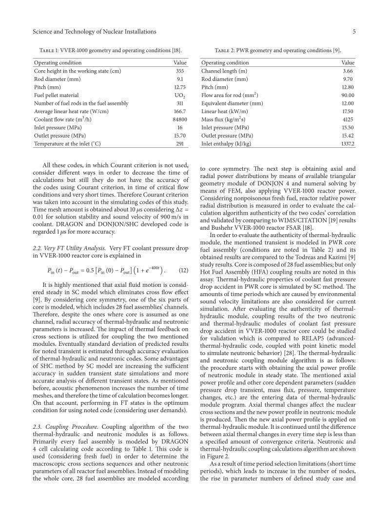
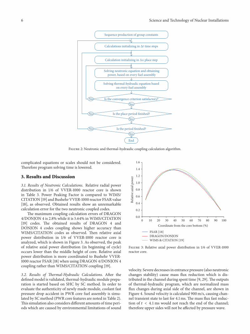
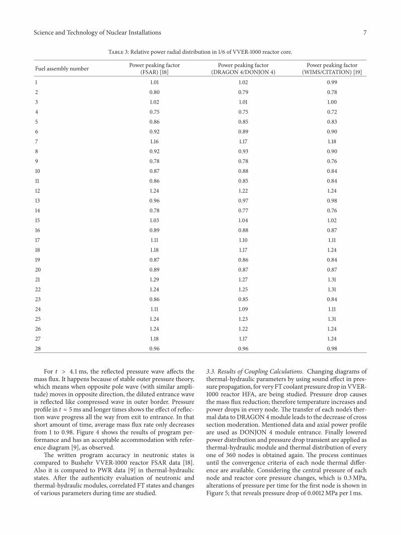
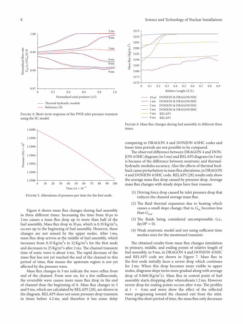
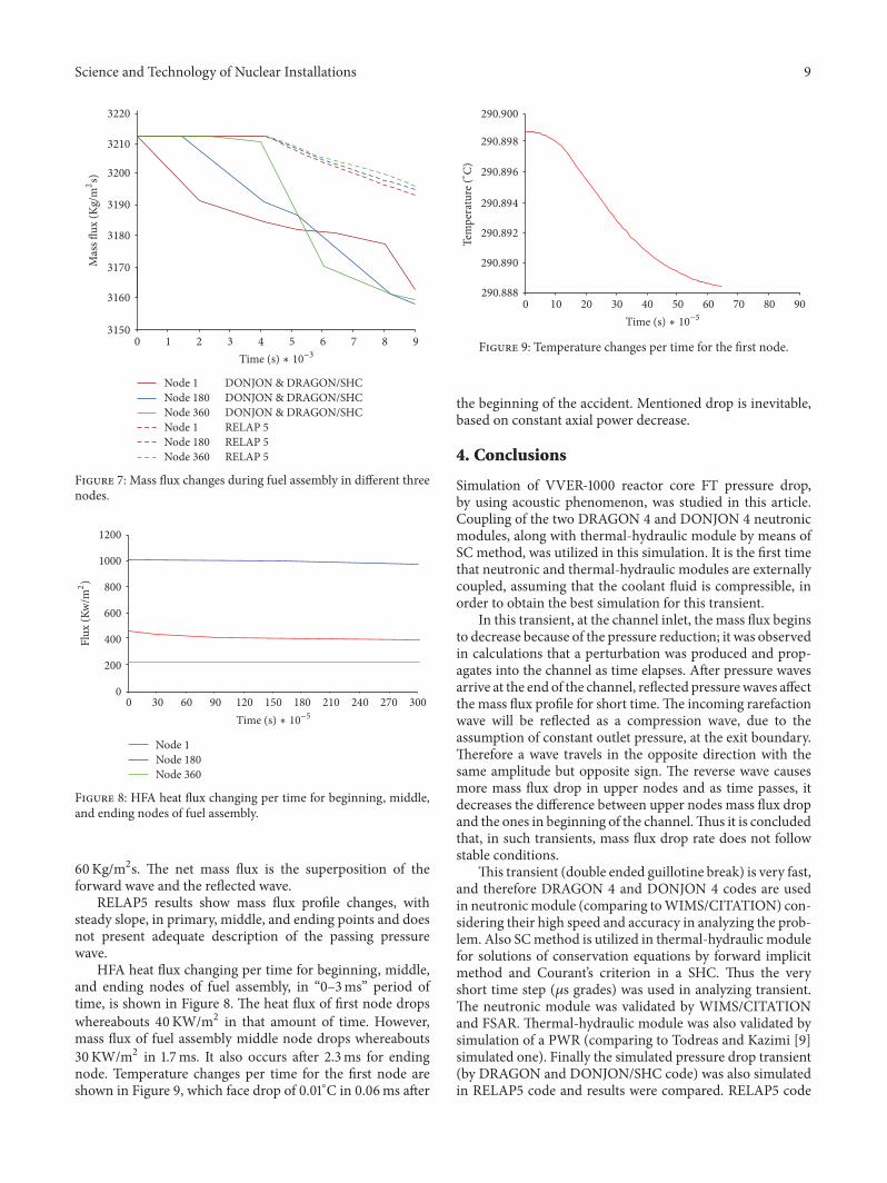
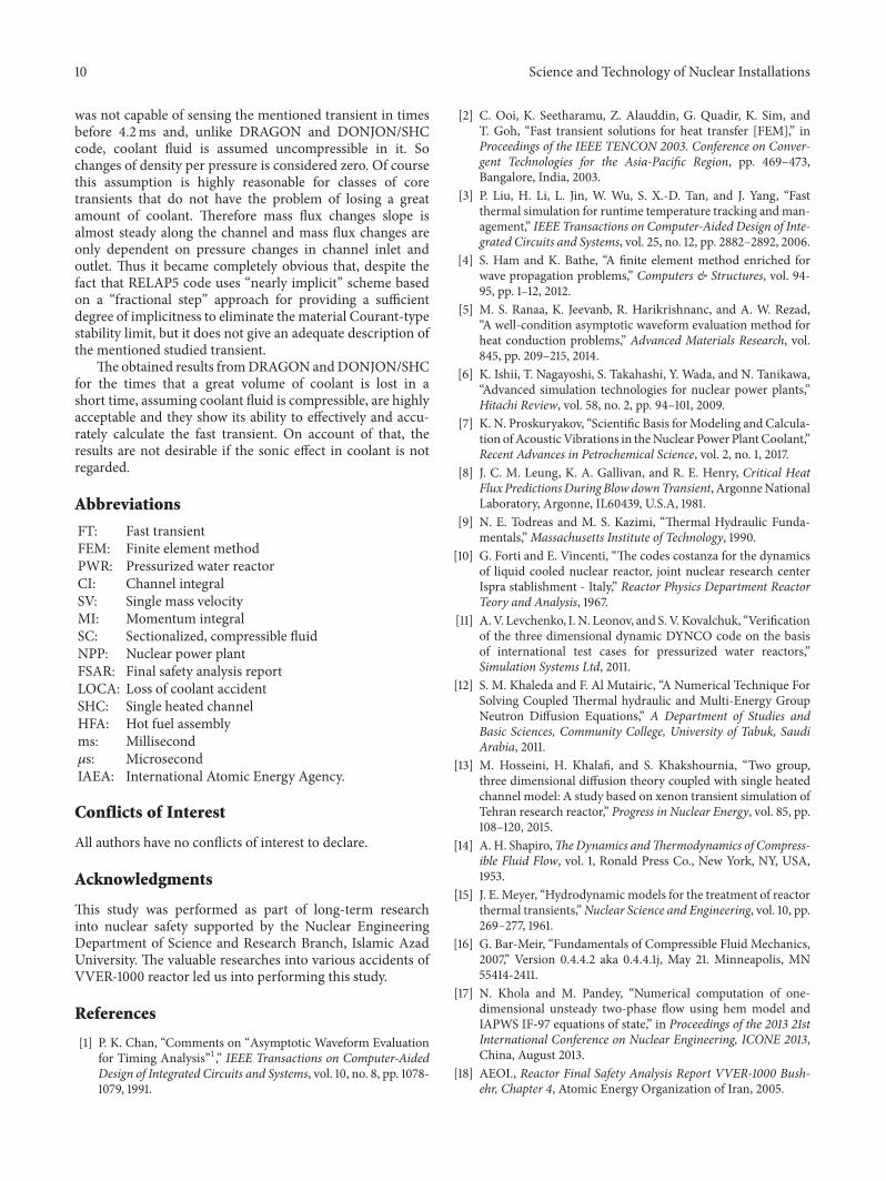
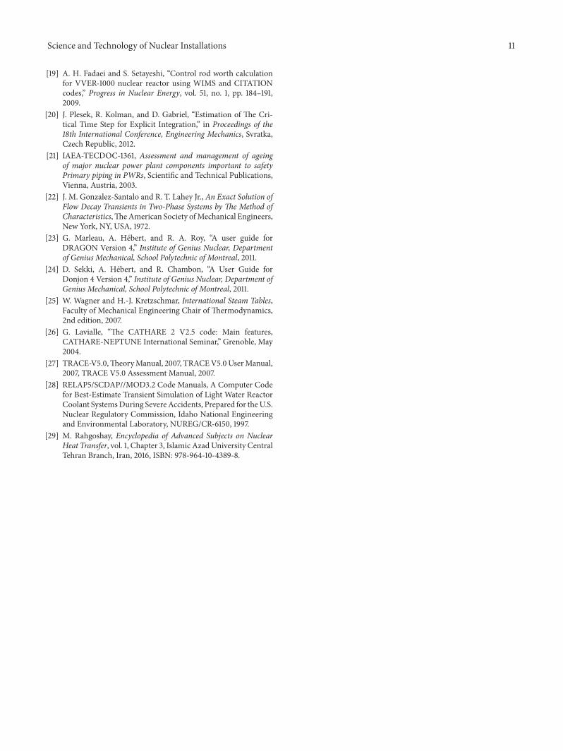

Hindawiwwwhindawicom Volume 2018
Nuclear InstallationsScience and Technology of
TribologyAdvances in
Hindawiwwwhindawicom Volume 2018
International Journal of
AerospaceEngineeringHindawiwwwhindawicom Volume 2018
OpticsInternational Journal of
Hindawiwwwhindawicom Volume 2018
Antennas andPropagation
International Journal of
Hindawiwwwhindawicom Volume 2018
Power ElectronicsHindawiwwwhindawicom Volume 2018
Advances in
CombustionJournal of
Hindawiwwwhindawicom Volume 2018
Journal of
Hindawiwwwhindawicom Volume 2018
Renewable Energy
Acoustics and VibrationAdvances in
Hindawiwwwhindawicom Volume 2018
EnergyJournal of
Hindawiwwwhindawicom Volume 2018
Hindawiwwwhindawicom
Journal ofEngineeringVolume 2018
Hindawiwwwhindawicom Volume 2018
International Journal ofInternational Journal ofPhotoenergy
Hindawiwwwhindawicom Volume 2018
Solar EnergyJournal of
Hindawiwwwhindawicom Volume 2018
Shock and Vibration
Hindawiwwwhindawicom Volume 2018
Advances in Condensed Matter Physics
International Journal of
RotatingMachinery
Hindawiwwwhindawicom Volume 2018
Hindawiwwwhindawicom Volume 2018
High Energy PhysicsAdvances in
Hindawiwwwhindawicom Volume 2018
Active and Passive Electronic Components
Hindawi Publishing Corporation httpwwwhindawicom Volume 2013Hindawiwwwhindawicom
The Scientific World Journal
Volume 2018
Submit your manuscripts atwwwhindawicom