Embed Size (px)
Citation preview
Study of G0FAH Off Centre Fed Dipole (OCFD)
(40m-20m-15m 10m)
Bill Wright (G0FAH) described his 4-band OCFD In QST during February 1996. The Idea for the antenna came from QSO’s with
European radio amateurs who said they were using the FD3 antenna. After investigating the FD3 3-band 40-20-10m OCFD, he
came up with a way to add the 15m band and the G0FAH 4-band antenna was born. The result is an antenna, similar to the 1950’s
Windom, that was also fed with 300Ω twin lead feeder the difference being the addition of a tuned length of feeder and a dual
ratio balun.
Bill claimed that the antenna is usable on most bands without a tuner (SWR <2:1) by adding a 1/4 λ wave transmission line
impedance transformer cut for 15m and changing the balun ratio to 1:1. The inconvenience of the switched balun can be
overcome if the feeder end and balun are brought into the shack. Using a tuner the antenna also works on 30, 17 &12m.
Bill used a quarter wave impedance transformer made from bare wire (VF=0.95) therefore, the length of the matching section
is 3.4m (11.14 ft). To reach the antenna feed point, the overall length of feeder should be an odd multiple of 3.4m, but Bill
stated that, for best results on all 4 bands, the open feeder "ladder" line lengths are :-
16.76m (55 ft) or 33.83m (111 ft) 450Ω ladder line (recommended ).
15.24m (50 ft) or 30.48m (100 ft) 300Ω ladder line can also be used.
The first set of figures Bill suggested are approx 5 x 11.143 but the second set are 10x and not an odd multiple. He also states
that these lengths should get to back to the shack with room to spare, so perhaps he implies a bit of trimming is required.
See appendix for details of calculations
HISTORY
Since I have my own version of the FD3 antenna, I was intrigued by this modification and decided to model the antenna.
This proved more difficult than I first thought and so I sought help from the Yahoo groups for MMANA-GAL &
RSGBTECH. My special thanks go to Alastair NH7O, Steve G3TXQ and Dave G3YMC, who provided a copy of the original
ARRL QST article “ Four Bands, Off Center Feb 1996”, to enable me to write this article.
Mario G8ODE
14.0m
(46.0ft)
50Ω
Coax
1/3 2/3
4:1
Switched Balun
Transformer
4:1 +1:1
(See notes)
300Ω 1/4 λ
Open-Wire
Impedance
Transformer
(See notes)
9.43m
(50 ft)
7.01m
(23.0ft)
4:1 1:1
GRAPHICS BY G8ODE July 2012 iss 1.3
Study of G0FAH Off Centre Fed Dipole (OCFD)
(40m-20m-15m 10m)
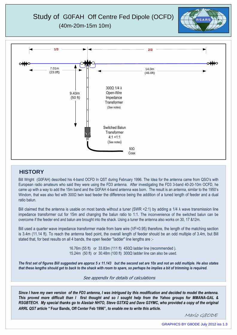
40m 20m 10m
The G0FAH 4-band antenna is modelled using MMANA-GAL basic freeware antennal analysis software. The model assumes
that antenna is 10.75m above “real” ground with a conductivity of 5mS/m and a dielectric of 13. Since MMANA-GAL cannot
cope with changing the feed point impedance mid-calculation, two separate models were created. The model was initially
created with a feed point impedance of 200Ω and optimised on all 4 bands. The file was saved as G0FAH 200R.maa. The
SWR results simulating the 4:1 balun connected to a 300O twin line are shown below
The MMANA-GAL 40m-20m-10m RESULTS FOR THE G0FAH (File G0FAH-200R.mma)
The results give a good idea of how the antenna may perform in locations where there are no trees, bushes or metal objects in the
near field. The results differ slightly from Bill Wright’s results for his 40ft high OCFD with 300Ω feeder. The model’s lower height
only affects the 40m band where the SWR is 3.33:1. The antenna current plots at the top of the page show that the vertical feeder
radiates in each case. This is not necessarily a bad thing since this can improve the antennas DX operation.
GRAPHICS BY G8ODE July 2012 iss 1.3
Study of G0FAH Off Centre Fed Dipole (OCFD)
(40m-20m-15m 10m)
40m 20m 10m
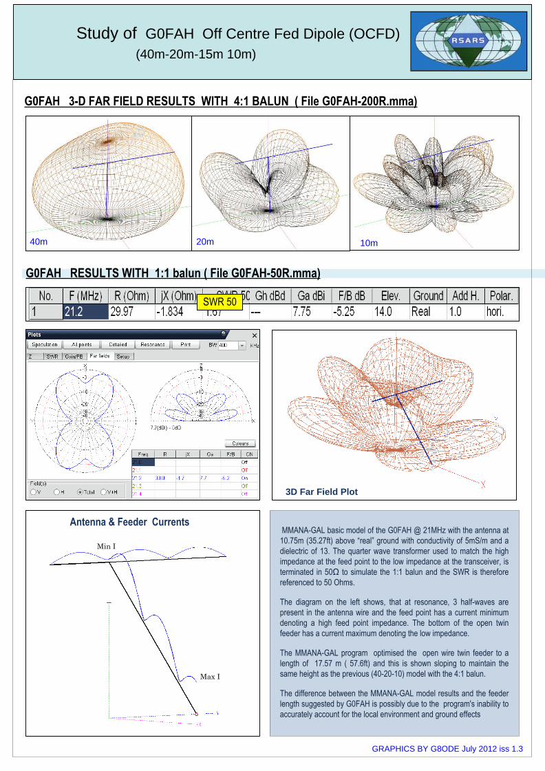
G0FAH 3-D FAR FIELD RESULTS WITH 4:1 BALUN ( File G0FAH-200R.mma)
G0FAH RESULTS WITH 1:1 balun ( File G0FAH-50R.mma)
MMANA-GAL basic model of the G0FAH @ 21MHz with the antenna at
10.75m (35.27ft) above “real” ground with conductivity of 5mS/m and a
dielectric of 13. The quarter wave transformer used to match the high
impedance at the feed point to the low impedance at the transceiver, is
terminated in 50Ω to simulate the 1:1 balun and the SWR is therefore
referenced to 50 Ohms.
The diagram on the left shows, that at resonance, 3 half-waves are
present in the antenna wire and the feed point has a current minimum
denoting a high feed point impedance. The bottom of the open twin
feeder has a current maximum denoting the low impedance.
The MMANA-GAL program optimised the open wire twin feeder to a
length of 17.57 m ( 57.6ft) and this is shown sloping to maintain the
same height as the previous (40-20-10) model with the 4:1 balun.
The difference between the MMANA-GAL model results and the feeder
length suggested by G0FAH is possibly due to the program's inability to
accurately account for the local environment and ground effects
SWR 50
Min I
Max I
Antenna & Feeder Currents
3D Far Field Plot
GRAPHICS BY G8ODE July 2012 iss 1.3
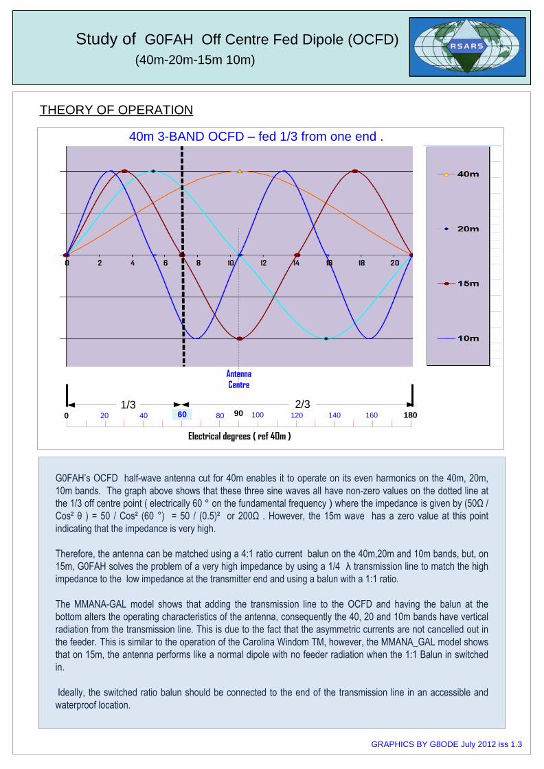
G0FAH’s OCFD half-wave antenna cut for 40m enables it to operate on its even harmonics on the 40m, 20m,
10m bands. The graph above shows that these three sine waves all have non-zero values on the dotted line at
the 1/3 off centre point ( electrically 60 ° on the fundamental frequency ) where the impedance is given by (50Ω /
Cos² θ ) = 50 / Cos² (60 °) = 50 / (0.5)² or 200Ω . However, the 15m wave has a zero value at this point
indicating that the impedance is very high.
Therefore, the antenna can be matched using a 4:1 ratio current balun on the 40m,20m and 10m bands, but, on
15m, G0FAH solves the problem of a very high impedance by using a 1/4 λ transmission line to match the high
impedance to the low impedance at the transmitter end and using a balun with a 1:1 ratio.
The MMANA-GAL model shows that adding the transmission line to the OCFD and having the balun at the
bottom alters the operating characteristics of the antenna, consequently the 40, 20 and 10m bands have vertical
radiation from the transmission line. This is due to the fact that the asymmetric currents are not cancelled out in
the feeder. This is similar to the operation of the Carolina Windom TM, however, the MMANA_GAL model shows
that on 15m, the antenna performs like a normal dipole with no feeder radiation when the 1:1 Balun in switched
in.
Ideally, the switched ratio balun should be connected to the end of the transmission line in an accessible and
waterproof location.
Study of G0FAH Off Centre Fed Dipole (OCFD)
(40m-20m-15m 10m)
THEORY OF OPERATION
`
Antenna
Centre
1/3 2̀/3
40m 3-BAND OCFD – fed 1/3 from one end .
20 40 60 80 90 100 120 140 160 1800
Electrical degrees ( ref 40m )
GRAPHICS BY G8ODE July 2012 iss 1.3
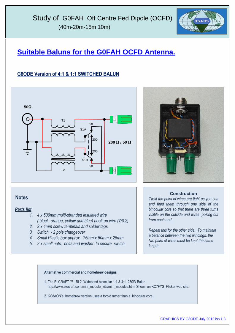
Suitable Baluns for the G0FAH OCFD Antenna.
Study of G0FAH Off Centre Fed Dipole (OCFD)
(40m-20m-15m 10m)
G8ODE Version of 4:1 & 1:1 SWITCHED BALUN
Notes
Parts list
1. 4 x 500mm multi-stranded insulated wire
( black, orange, yellow and blue) hook up wire (7/0.2)
2. 2 x 4mm screw terminals and solder tags
3. Switch - 2 pole changeover
4. Small Plastic box approx 75mm x 50mm x 25mm
5. 2 x small nuts, bolts and washer to secure switch.
Construction
Twist the pairs of wires are tight as you can
and feed them through one side of the
binocular core so that there are three turns
visible on the outside and wires poking out
from each end.
Repeat this for the other side. To maintain
a balance between the two windings, the
two pairs of wires must be kept the same
length.
200 Ω / 50 Ω
50Ω
S1A
S1B
T1
T2
50
50
200
200
Alternative commercial and homebrew designs
1. The ELCRAFT ™ BL2 Wideband binocular 1:1 & 4:1 250W Balun
http://www.elecraft.com/mini_module_kits/mini_modules.htm. Shown on KC7FYS Flicker web site.
2. KC8AON’s homebrew version uses a toroid rather than a binocular core .
GRAPHICS BY G8ODE July 2012 iss 1.3
Useful link:- http://www.arcticpeak.com/antennapages/quarter-wave_transformer.htm
Study of G0FAH Off Centre Fed Dipole (OCFD)
(40m-20m-15m 10m)
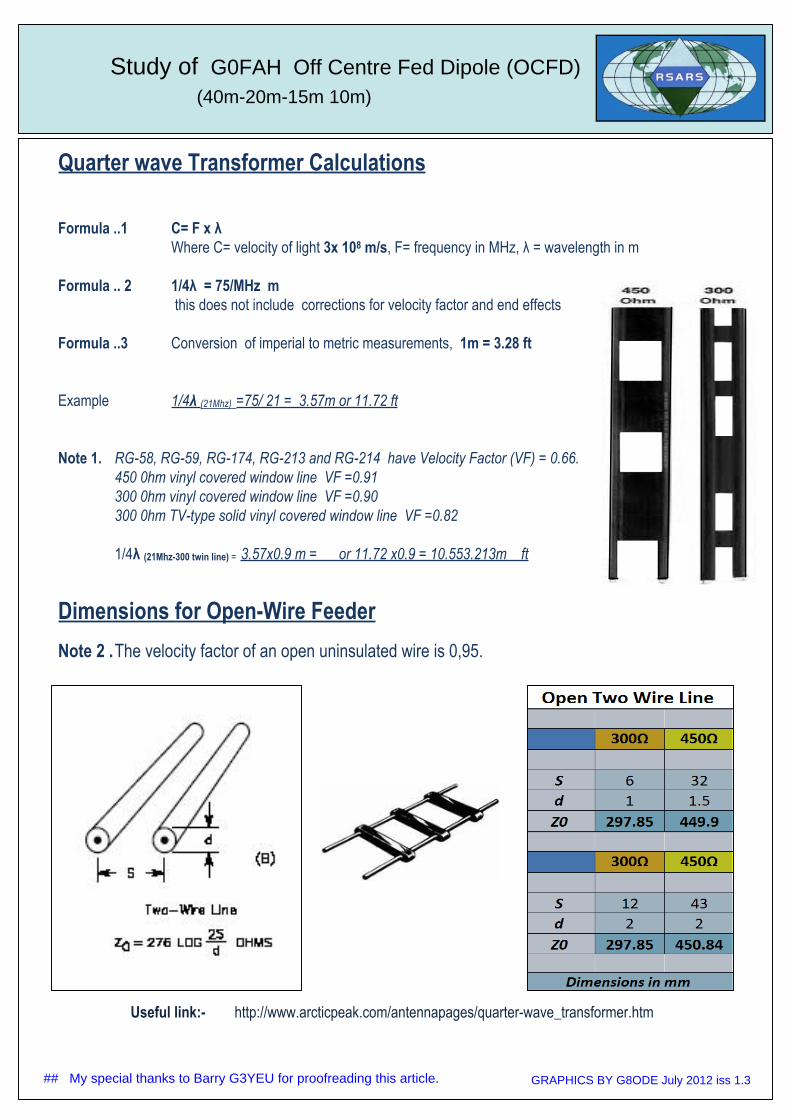
Quarter wave Transformer Calculations
Formula ..1 C= F x λ
Where C= velocity of light 3x 10⁸ m/s, F= frequency in MHz, λ = wavelength in m
Formula .. 2 1/4λ = 75/MHz m
this does not include corrections for velocity factor and end effects
Formula ..3 Conversion of imperial to metric measurements, 1m = 3.28 ft
Example 1/4λ (21Mhz) =75/ 21 = 3.57m or 11.72 ft
Note 1. RG-58, RG-59, RG-174, RG-213 and RG-214 have Velocity Factor (VF) = 0.66.
450 0hm vinyl covered window line VF =0.91
300 0hm vinyl covered window line VF =0.90
300 0hm TV-type solid vinyl covered window line VF =0.82
1/4λ (21Mhz-300 twin line) = 3.57x0.9 m = or 11.72 x0.9 = 10.553.213m ft
Dimensions for Open-Wire Feeder
Note 2 .The velocity factor of an open uninsulated wire is 0,95.
GRAPHICS BY G8ODE July 2012 iss 1.3## My special thanks to Barry G3YEU for proofreading this article.