Embed Size (px)
Citation preview
Study of Marcellus and Utica Well
Borehole Stability in Longwall Mining Areas
Mark E. Limbruner GISP
Range Resources-Appalachia, LLC
Thank You Locate15 & GITA Australia – New Zealand
Mark E. Limbruner, GISP
•Over 33 years of experience in mapping, CAD and GIS
•12 years within the oil and gas exploration industry
•2 years with a GIS consulting firm
•10 years in the environmental engineering industry
•3 years in the coal mining / exploration industry
•6 years at Range Resources - Marcellus Shale GIS department
•Co-Chair of the EnerGIS Conference 2013-2015
•President GITA North America 2015-2016
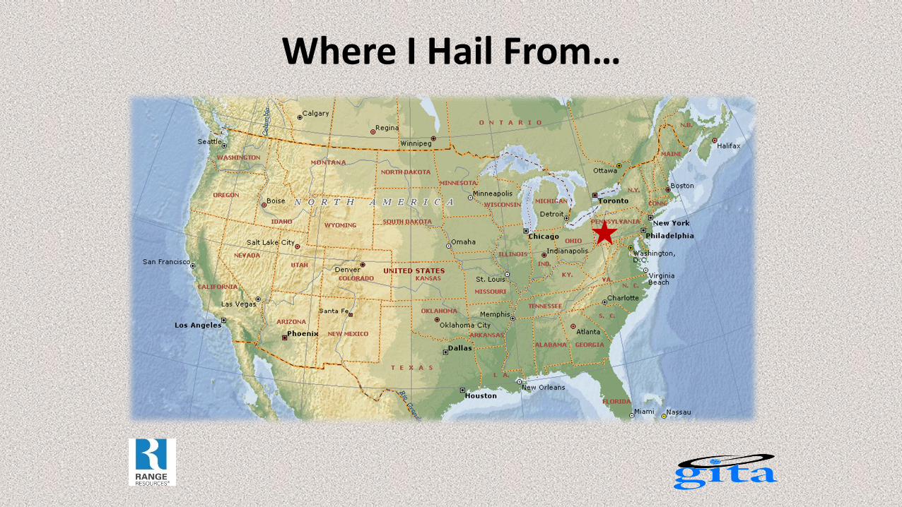
Where I Hail From…

A Bit on Home…
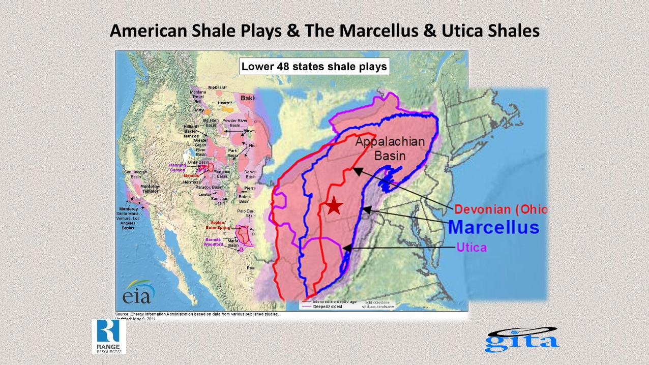
American Shale Plays & The Marcellus & Utica Shales
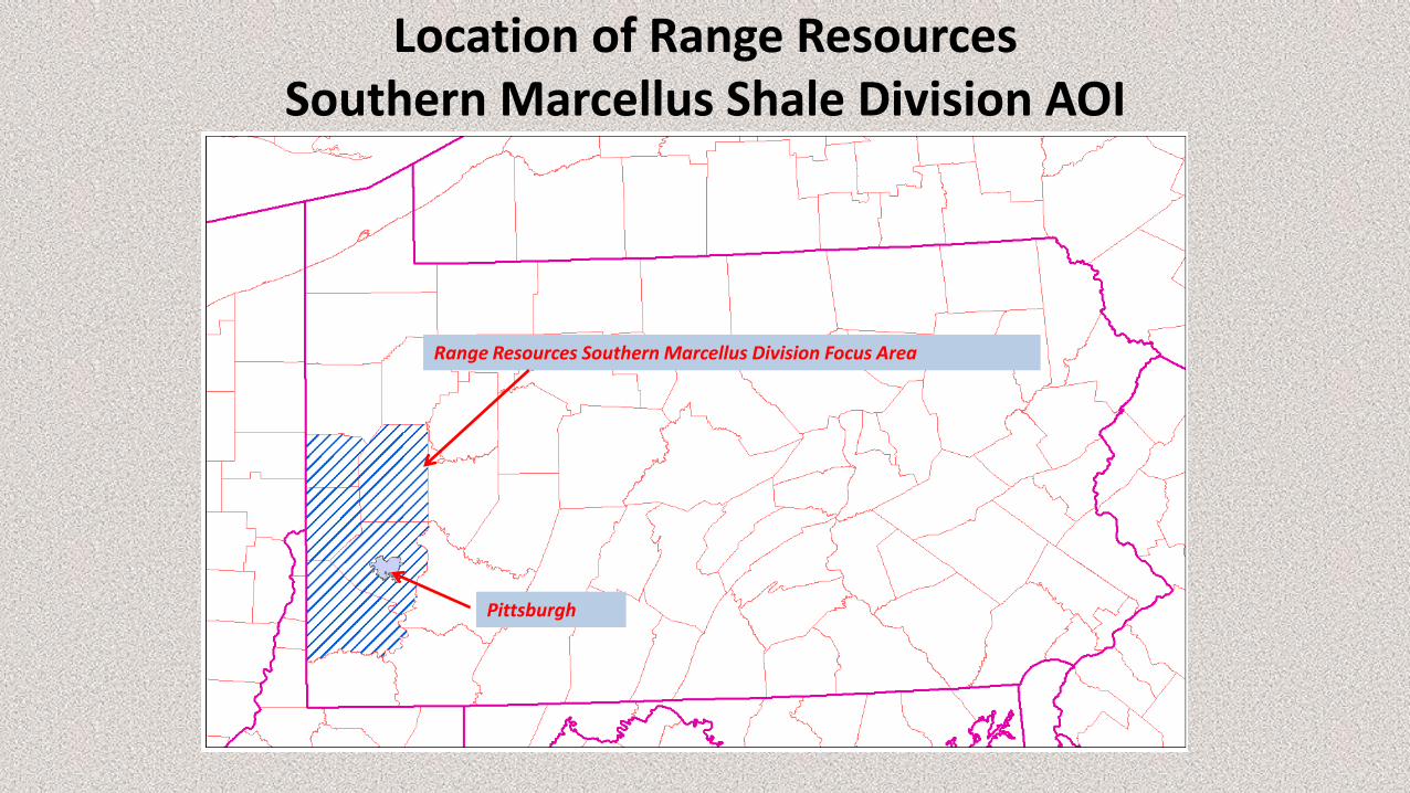
Location of Range Resources Southern Marcellus Shale Division AOI
Range Resources Southern Marcellus Division Focus Area
Pittsburgh
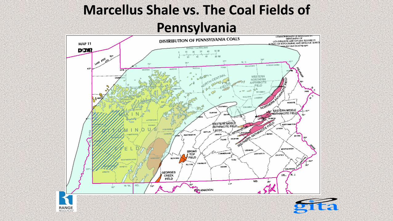
Marcellus Shale vs. The Coal Fields of Pennsylvania
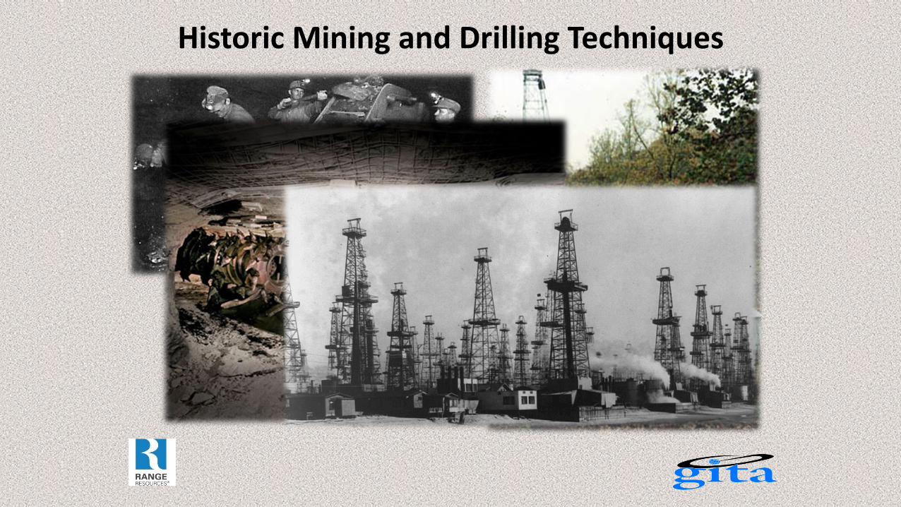
Historic Mining and Drilling Techniques
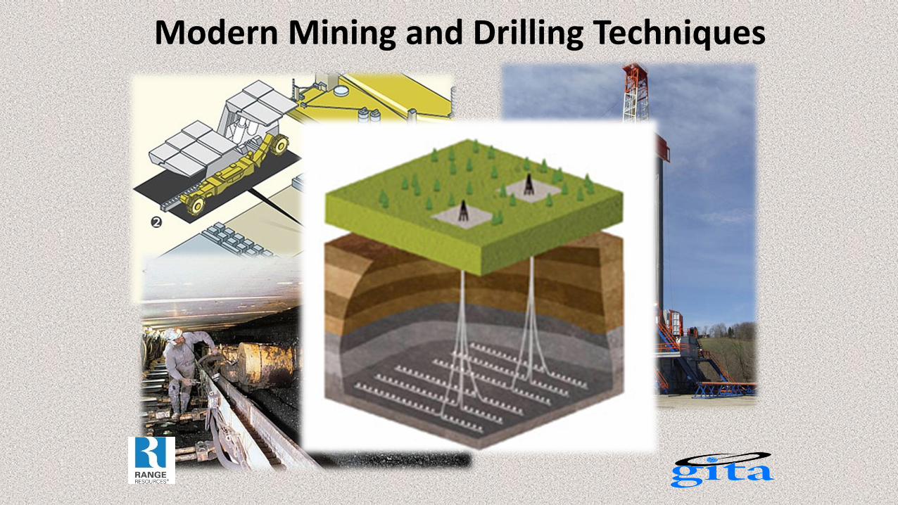
Modern Mining and Drilling Techniques
Conflict of Modern Mining and Drilling Techniques
•Over 95% of mineral estates in Southwestern Pennsylvania, have their mineral rights privately owned.
•The bulk of the tracts leased for gas drilling have their coal and natural gas rights severed. Those coal rights are often owned or leased by coal mining companies
•Pennsylvania state law insures that both the coal and gas companies have an equal right to access and enjoy their respective mineral estates.
•The safety and stability of the wellbores drilled in and adjacent to mines is a major concern to both the gas and coal companies.
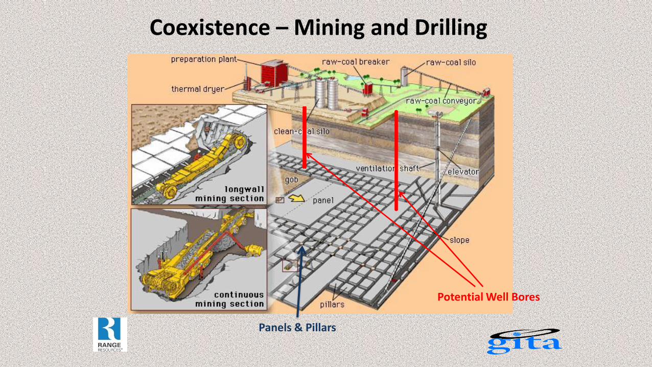
Coexistence – Mining and Drilling
Panels & Pillars
Potential Well Bores
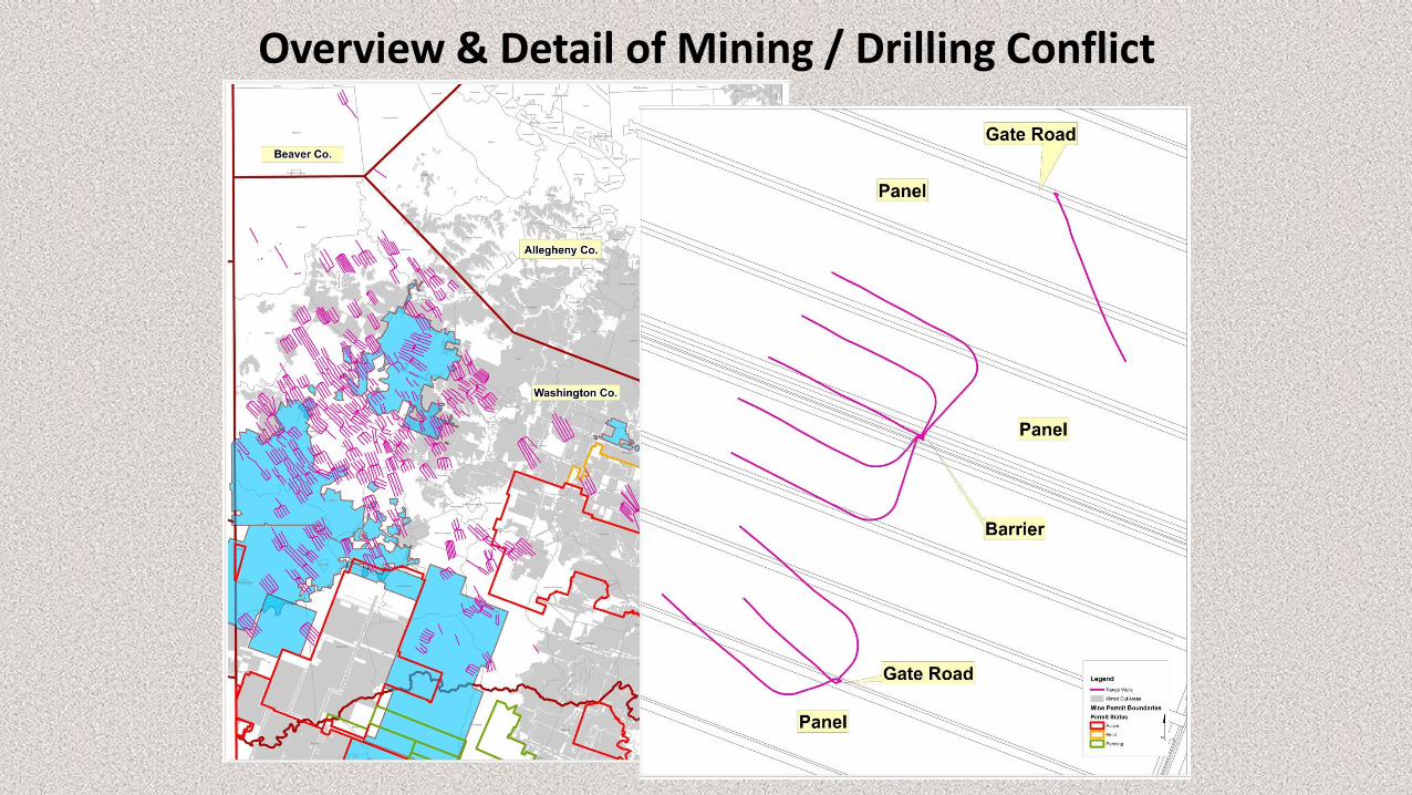
Overview & Detail of Mining / Drilling Conflict
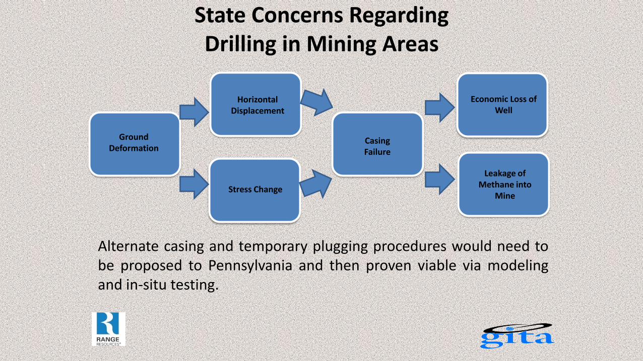
State Concerns Regarding Drilling in Mining Areas
Alternate casing and temporary plugging procedures would need to be proposed to Pennsylvania and then proven viable via modeling and in-situ testing.
Ground Deformation
Horizontal Displacement
Stress Change
Casing Failure
Economic Loss of Well
Leakage of Methane into
Mine
Proposed Study:
1. To use a finite element analysis modeling to simulate the complex ground condition in longwall mining areas and to quantify the factors affecting the wellbore stability.
2. To carry out an in-situ testing of various well bore construction regimens in order to evaluate current and proposed well bore casing designs.
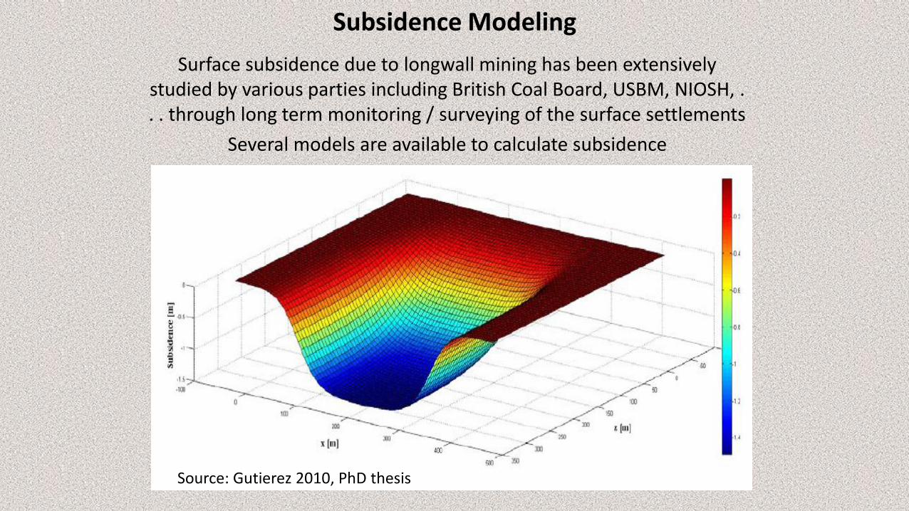
Subsidence Modeling
Surface subsidence due to longwall mining has been extensively studied by various parties including British Coal Board, USBM, NIOSH, . . . through long term monitoring / surveying of the surface settlements
Several models are available to calculate subsidence
Source: Gutierez 2010, PhD thesis
Predictive Model for Wellbore Damage
ABAQUS 3D Finite Element Model Based on Actual Site Geology • Detailed Geology from Core samples or Gamma Ray Logs • Rock Properties: Strength, Young’s Moduli and Poisson’s Ratio
Rock Interfaces Cohesion • Strong Interfaces at: Limestone / Sandstone, Sandstone / Sandy Shale • Weak Interfaces at: Coal / Limestone, Coal / Sandstone, Coal / Sandy Shale Limestone / Claystone, Etc. = Zero Cohesion. Study to be Based on True Mining and Site Geometry • Underground Longwall Panel Development Entry • Detailed Test Well / Monitoring Well Geometry
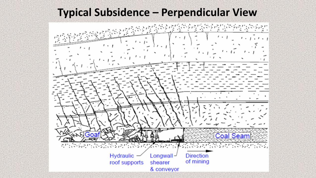
Typical Subsidence – Perpendicular View
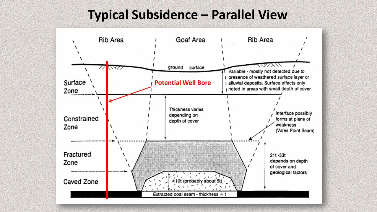
Typical Subsidence – Parallel View
Potential Well Bore
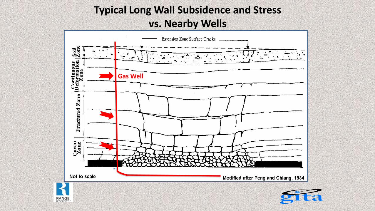
Typical Long Wall Subsidence and Stress vs. Nearby Wells
Gas Well
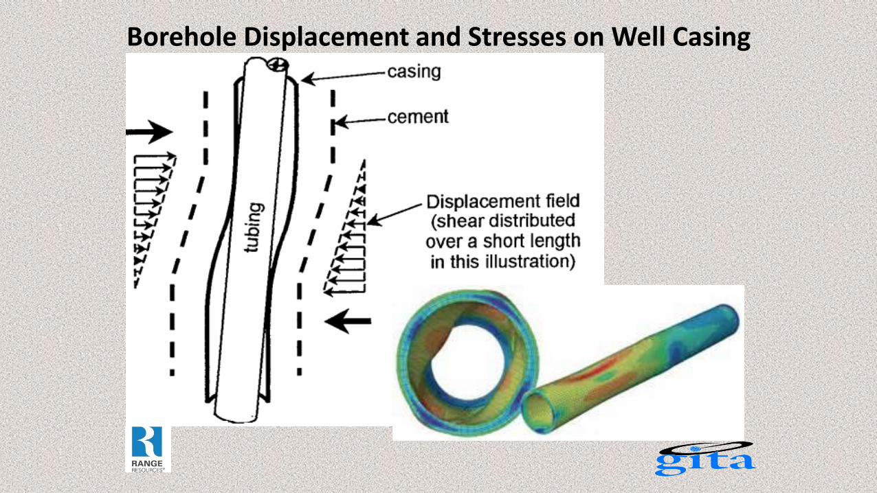
Borehole Displacement and Stresses on Well Casing
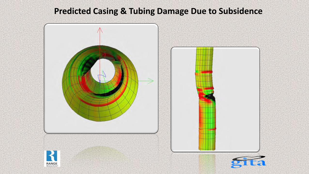
Predicted Casing & Tubing Damage Due to Subsidence
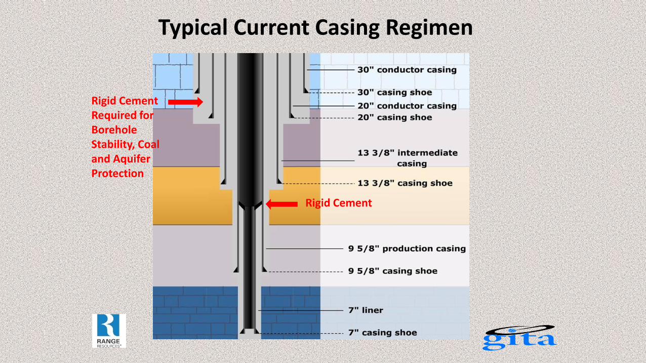
Typical Current Casing Regimen
Rigid Cement Required for Borehole Stability, Coal and Aquifer Protection
Rigid Cement
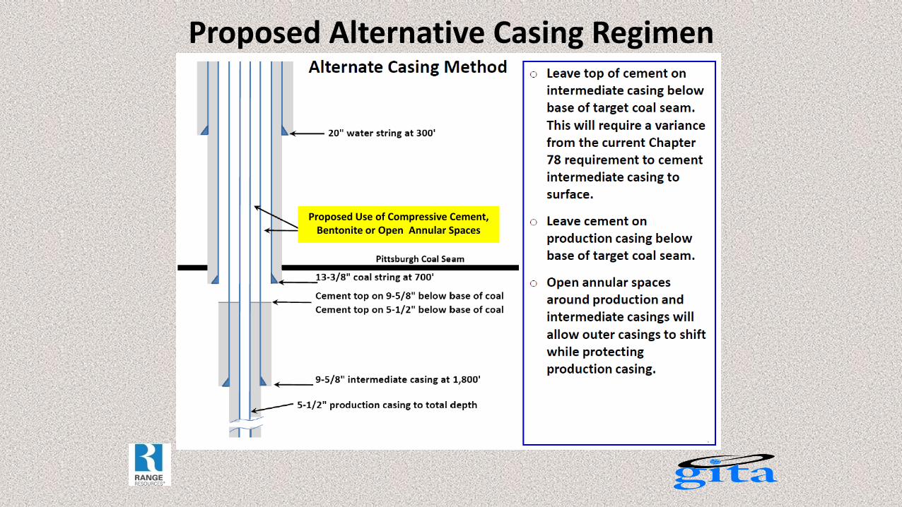
Proposed Alternative Casing Regimen
Alternate to Rigid Cement
Proposed Use of Compressive Cement, Bentonite or Open Annular Spaces
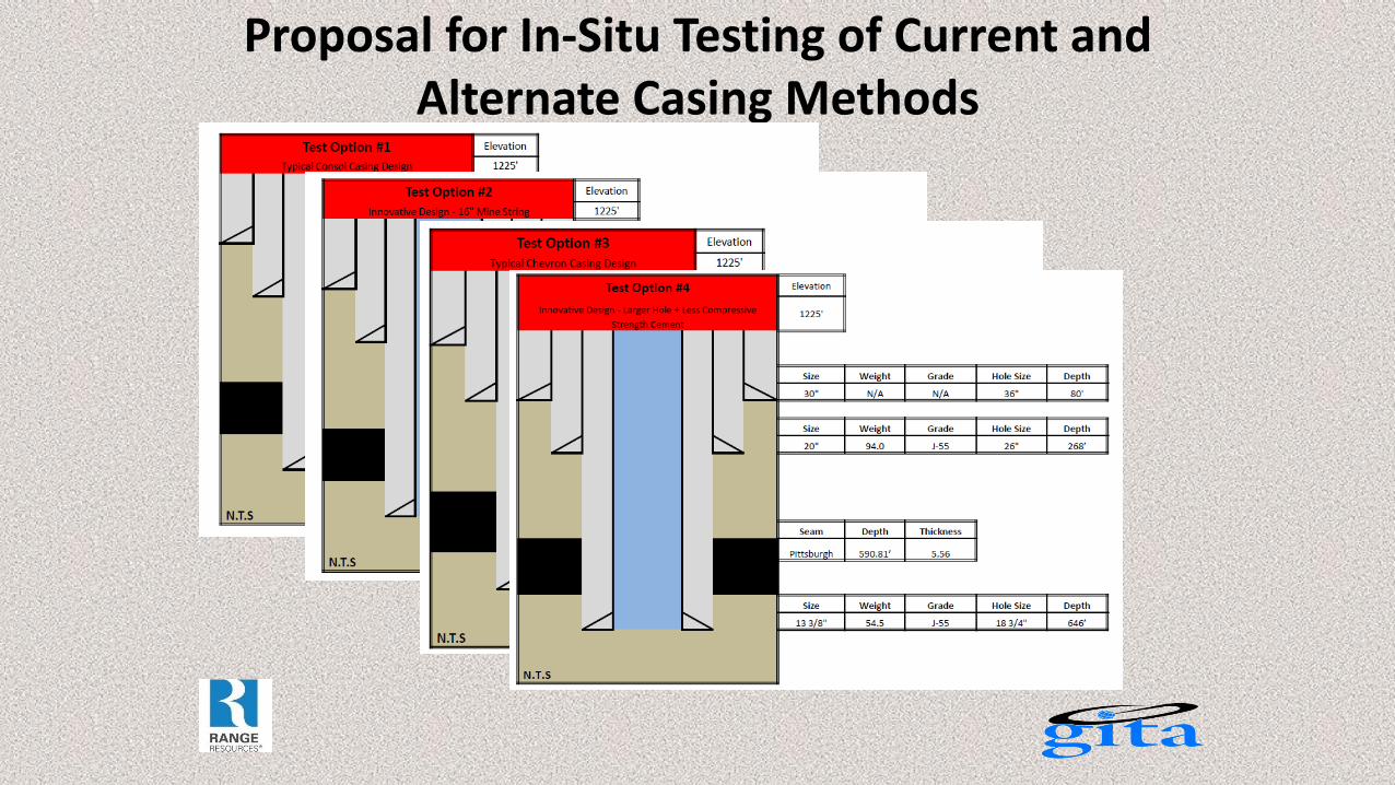
Proposal for In-Situ Testing of Current and Alternate Casing Methods
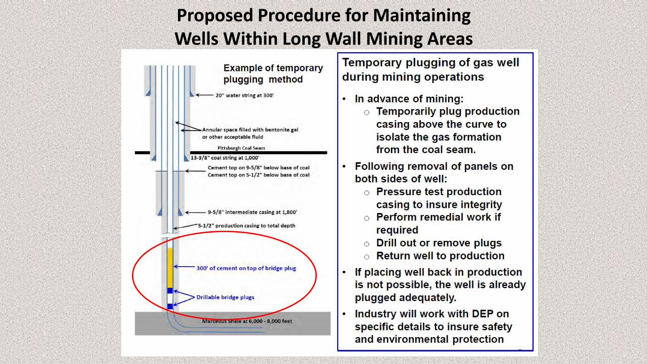
Proposed Procedure for Maintaining Wells Within Long Wall Mining Areas
In-Situ Testing
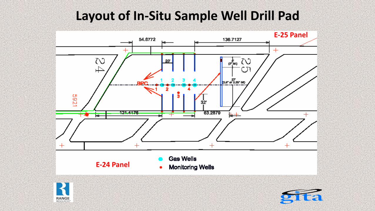
Layout of In-Situ Sample Well Drill Pad E-25 Panel
E-24 Panel
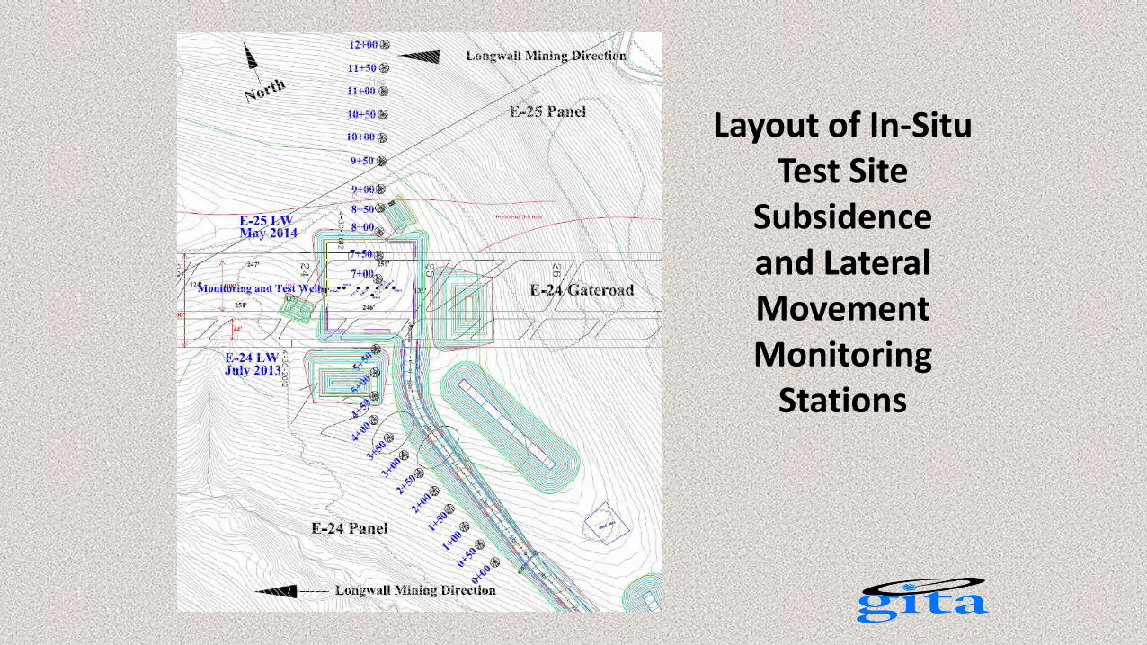
Layout of In-Situ Test Site
Subsidence and Lateral Movement Monitoring
Stations
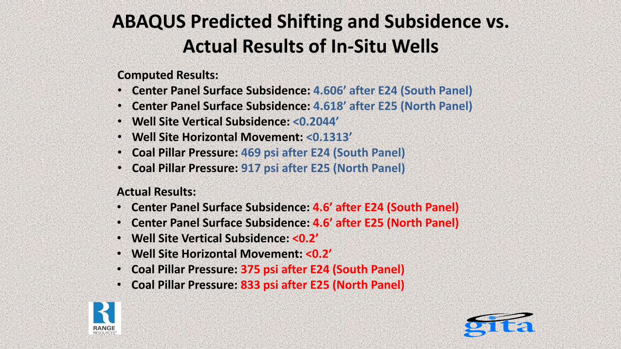
ABAQUS Predicted Shifting and Subsidence vs. Actual Results of In-Situ Wells
Computed Results: • Center Panel Surface Subsidence: 4.606’ after E24 (South Panel) • Center Panel Surface Subsidence: 4.618’ after E25 (North Panel) • Well Site Vertical Subsidence: <0.2044’ • Well Site Horizontal Movement: <0.1313’ • Coal Pillar Pressure: 469 psi after E24 (South Panel) • Coal Pillar Pressure: 917 psi after E25 (North Panel)
Actual Results: • Center Panel Surface Subsidence: 4.6’ after E24 (South Panel) • Center Panel Surface Subsidence: 4.6’ after E25 (North Panel) • Well Site Vertical Subsidence: <0.2’ • Well Site Horizontal Movement: <0.2’ • Coal Pillar Pressure: 375 psi after E24 (South Panel) • Coal Pillar Pressure: 833 psi after E25 (North Panel)
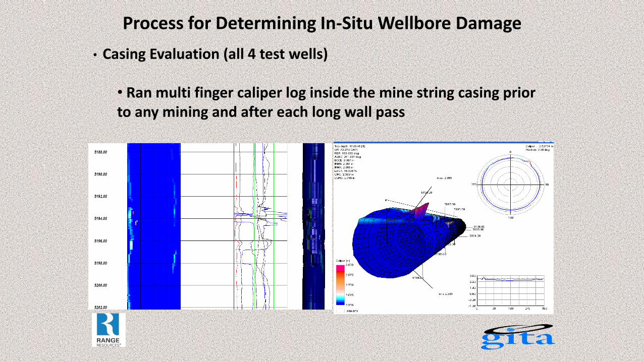
Process for Determining In-Situ Wellbore Damage
• Casing Evaluation (all 4 test wells)
• Ran multi finger caliper log inside the mine string casing prior to any mining and after each long wall pass
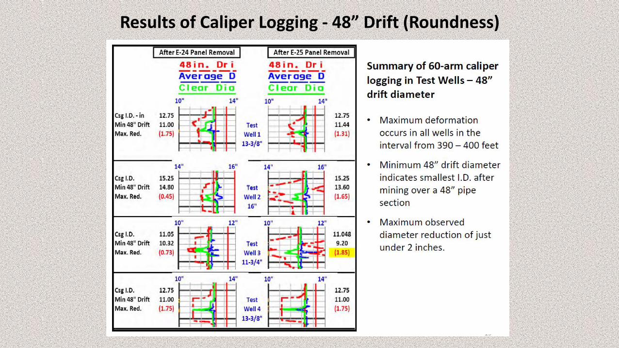
Results of Caliper Logging - 48” Drift (Roundness)
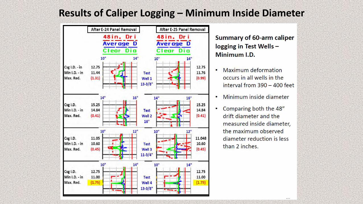
Results of Caliper Logging – Minimum Inside Diameter
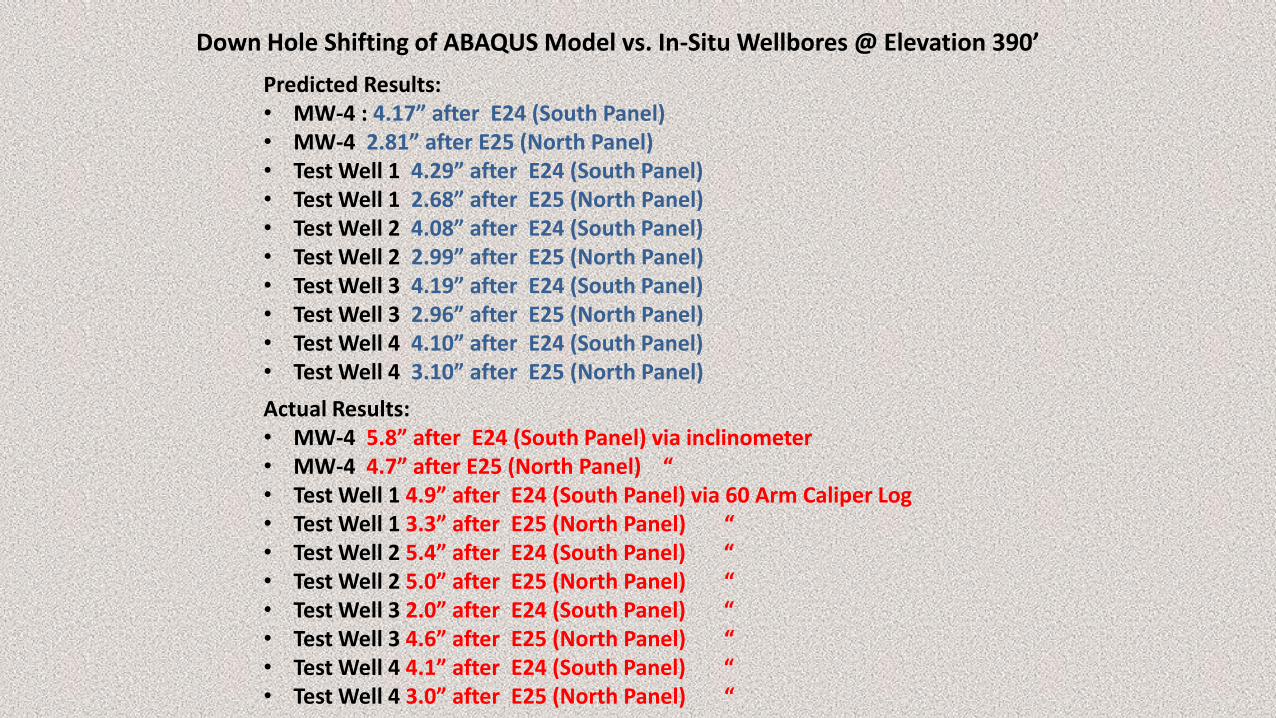
Down Hole Shifting of ABAQUS Model vs. In-Situ Wellbores @ Elevation 390’
Predicted Results: • MW-4 : 4.17” after E24 (South Panel) • MW-4 2.81” after E25 (North Panel) • Test Well 1 4.29” after E24 (South Panel) • Test Well 1 2.68” after E25 (North Panel) • Test Well 2 4.08” after E24 (South Panel) • Test Well 2 2.99” after E25 (North Panel) • Test Well 3 4.19” after E24 (South Panel) • Test Well 3 2.96” after E25 (North Panel) • Test Well 4 4.10” after E24 (South Panel) • Test Well 4 3.10” after E25 (North Panel)
Actual Results: • MW-4 5.8” after E24 (South Panel) via inclinometer • MW-4 4.7” after E25 (North Panel) “ • Test Well 1 4.9” after E24 (South Panel) via 60 Arm Caliper Log • Test Well 1 3.3” after E25 (North Panel) “ • Test Well 2 5.4” after E24 (South Panel) “ • Test Well 2 5.0” after E25 (North Panel) “ • Test Well 3 2.0” after E24 (South Panel) “ • Test Well 3 4.6” after E25 (North Panel) “ • Test Well 4 4.1” after E24 (South Panel) “ • Test Well 4 3.0” after E25 (North Panel) “
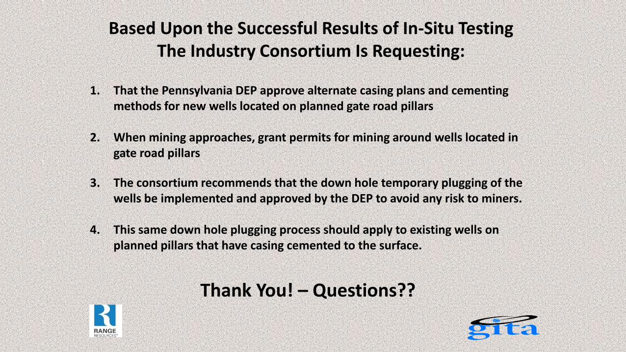
Based Upon the Successful Results of In-Situ Testing The Industry Consortium Is Requesting:
1. That the Pennsylvania DEP approve alternate casing plans and cementing methods for new wells located on planned gate road pillars
2. When mining approaches, grant permits for mining around wells located in gate road pillars
3. The consortium recommends that the down hole temporary plugging of the wells be implemented and approved by the DEP to avoid any risk to miners.
4. This same down hole plugging process should apply to existing wells on planned pillars that have casing cemented to the surface.
Thank You! – Questions??