Embed Size (px)
Citation preview

HAL Id: tel-00939092https://tel.archives-ouvertes.fr/tel-00939092
Submitted on 30 Jan 2014
HAL is a multi-disciplinary open accessarchive for the deposit and dissemination of sci-entific research documents, whether they are pub-lished or not. The documents may come fromteaching and research institutions in France orabroad, or from public or private research centers.
L’archive ouverte pluridisciplinaire HAL, estdestinée au dépôt et à la diffusion de documentsscientifiques de niveau recherche, publiés ou non,émanant des établissements d’enseignement et derecherche français ou étrangers, des laboratoirespublics ou privés.
Study of mechanisms ensuring service continuity forIKEv2 and IPsec protocols
Daniel Palomares Velasquez
To cite this version:Daniel Palomares Velasquez. Study of mechanisms ensuring service continuity for IKEv2 and IPsecprotocols. Architecture, space management. Institut National des Télécommunications, 2013. English.<NNT : 2013TELE0025>. <tel-00939092>
THESE DE DOCTORAT CONJOINT TELECOM SUDPARISet L’UNIVERSITE PIERRE ET MARIE CURIE
Specialite:
Ecole doctorale: Informatique, Telecommunications et Electronique de Paris
Presentee parDaniel Palomares Velasquez
Pour obtenir le grade deDocteur de Telecom SudParis
Etude de Mecanismes Assurant la Continuite de
Service de Protocoles IKEv2 et IPsec
Soutenue le 14 Novembre, 2013 No. de these: 2013TELE0025
Devant le jury compose par:
BONNIN Jean-Marie, Professeur HDR a Telecom Bretagne RapporteurCARLE Georg, Professeur a Technische Universitat Munchen RapporteurPUJOLLE Guy, Professeur a l’Universite Pierre et Marie Curie - LIP6 ExaminateurCOMBES Jean-Michel, Docteur et Ingenieur a Orange Labs de France Telecom R&D ExaminateurMIGAULT Daniel, Docteur et Ingenieur a Orange Labs de France Telecom R&D ExaminateurLAURENT Maryline, Professeur HDR a Telecom SudParis - Departement RST Directrice de These

ii

PhD THESIS AGREEMENT TELECOM SUDPARISAND UNIVERSITY PIERRE ET MARIE CURIE
Specialty:
Doctoral School: Informatique, Telecommunications et Electronique de Paris
PhD Thesis Dissertation byDaniel Palomares Velasquez
To obtain the degree of:Doctor of Telecom SudParis
Study of Mechanisms Ensuring Service Continuity
for IKEv2 and IPsec Protocols
Defense date: November 14th, 2013 No. of thesis: 2013TELE0025
Members of the jury:
BONNIN Jean-Marie, Professor HDR at Telecom Bretagne ReporterCARLE Georg, Professor at Technische Universitat Munchen ReporterPUJOLLE Guy, Professor at University Pierre et Marie Curie - LIP6 ExaminerCOMBES Jean-Michel, Doctor and Engineer at Orange Labs of France Telecom R&D ExaminerMIGAULT Daniel, Doctor and Engineer at Orange Labs of France Telecom R&D ExaminerLAURENT Maryline, Professor HDR at Telecom SudParis - Departement RST Thesis Director


Acknowledgments
First of all I would like to render thanks to every single person that help me out through all mycareer. Specially my parents, which are my biggest inspiration.
The first steps of this thesis were done thanks to Professor Maryline Laurent, my thesisdirector. I can only say thanks for her support and patience as well as for the time she hasconsecrate to this research.
Second, I would not be able to make this investigation without the help and supervision ofDaniel Migault. I admire his capability, creativity, professionalism and enthusiasm. Throughoutthese years, I have learned a lot from him and I am truly grateful.
I also had the opportunity to conduct several academic projects and internships. They allhave been a big source of apprenticeship to me.
I am also grateful towards Vincent Barriac, which I thank you for his investment in producingexcellent quality results concerning the last part of this thesis.
These persons also helped me throughout the achievement of my thesis: Wolfgang Velasquez,Martin Willi, Jean-Michel Combes, Hendrik Hendrik, Emmanuel Herbert, Aurelien Wally, JoseDaniel Gomes, Ana Maria.
Being part of Orange has been a truly remarkable experience for my professional career, andI Thank You All.
Daniel Palomares.
September 2013.
iii

iv

Abstract
During 2012, the global mobile traffic represented 70% more than 2011. The arrival of the 4Gtechnology introduced 19 times more traffic than non-4G sessions, and in 2013 the number ofmobile-connected to the Internet exceeded the number of human beings on earth. This scenariointroduces great pressure towards the Internet service providers (ISPs), which are called toensure access to the network and maintain its QoS. At short/middle term, operators will relayon alternative access networks in order to maintain the same performance characteristics. Thus,the traffic of the clients might be offloaded from RANs to some other available access networks.However, the same security level is not ensured by those wireless access networks. Femtocells,WiFi or WiMAX (among other wireless technologies), must rely on some mechanism to securethe communications and avoid untrusted environments.
Operators are mainly using IPsec to extend a security domain over untrusted networks.This introduces new challenges in terms of performance and connectivity for IPsec. This thesisconcentrates on the study of the mechanism considering to improve the IPsec protocol in termsof continuity of service.
The continuity of service, also known as resilience, becomes crucial when offloading the trafficfrom RANs to other access networks. This is why we first concentrate our effort in defining theprotocols ensuring an IP communication: IKEv2 and IPsec. Then, we present a detailed studyof the parameters needed to keep a VPN session alive, and we demonstrate that it is possibleto dynamically manage a VPN session between different gateways. Some of the reasons thatjustify the management of VPN sessions is to provide high availability, load sharing or loadbalancing features for IPsec connections. These mechanisms increase the continuity of serviceof IPsec-based communication. For example, if for some reason a failure occurs to a securitygateway, the ISP should be able to overcome this situation and to provide mechanisms to ensurecontinuity of service to its clients.
Some new mechanisms have recently been implemented to provide High Availability overIPsec. The open source VPN project, StrongSwan, implemented a mechanism called ClusterIPin order to create a cluster of IPsec gateways. We merged ClusterIP with our own developments inorder to define two architectures: High Availability and Context Management over Mono-LANand Multi-LAN environments. We called Mono-LAN those architectures where the cluster ofsecurity gateways is configured under a single IP address, whereas Multi-LAN concerns thosearchitectures where different security gateways are configured with different IP addresses.
Performance measurements throughout the thesis show that transferring a VPN sessionbetween different gateways avoids re-authentication delays and reduce the amount of CPUconsumption and calculation of cryptographic material. From an ISP point of view, this couldbe used to avoid overloaded gateways, redistribution of the load, better network performances,
v

vi
improvements of the QoS, etc. The idea is to allow a peer to enjoy the continuity of a servicewhile maintaining the same security level that it was initially proposed.

Contents
1 Introduction 1
1.1 Architectures of Interest . . . . . . . . . . . . . . . . . . . . . . . . . . . . . . . . 2
1.1.1 Clustering IPsec Security Gateways . . . . . . . . . . . . . . . . . . . . . 2
1.1.2 Offload Architectures . . . . . . . . . . . . . . . . . . . . . . . . . . . . . 3
1.2 VPN Service description and technical challenges . . . . . . . . . . . . . . . . . . 7
1.2.1 High Availability of IPsec-based VPNs . . . . . . . . . . . . . . . . . . . . 7
1.2.2 Traffic Management of IPsec-based VPNs . . . . . . . . . . . . . . . . . . 8
1.3 Context Transfer is not designed for Mobility . . . . . . . . . . . . . . . . . . . . 9
1.4 Related work and position of our work . . . . . . . . . . . . . . . . . . . . . . . . 10
1.4.1 Position towards theoretical proposed architectures . . . . . . . . . . . . . 10
1.4.2 Position towards existing implementation . . . . . . . . . . . . . . . . . . 12
1.4.3 Detailed position towards High Availability vs. Mobility scenarios . . . . 13
1.5 Contributions . . . . . . . . . . . . . . . . . . . . . . . . . . . . . . . . . . . . . . 14
1.6 Thesis Organization . . . . . . . . . . . . . . . . . . . . . . . . . . . . . . . . . . 16
I Security for IP Networks 17
2 Roadmap of IPsec and IKEv2 protocols 19
2.1 Security Services . . . . . . . . . . . . . . . . . . . . . . . . . . . . . . . . . . . . 19
2.2 IPsec: Security Associations and Databases . . . . . . . . . . . . . . . . . . . . . 20
2.3 IPsec Protocols . . . . . . . . . . . . . . . . . . . . . . . . . . . . . . . . . . . . . 22
2.3.1 Authentication Header . . . . . . . . . . . . . . . . . . . . . . . . . . . . . 22
2.3.2 Encapsulation Security Payload . . . . . . . . . . . . . . . . . . . . . . . . 22
2.4 Security Management: Manual Vs. IKEv2 protocol . . . . . . . . . . . . . . . . . 23
vii

viii Contents
2.4.1 Exchange Description: IKE SA INIT . . . . . . . . . . . . . . . . . . . . . 24
2.4.2 Exchange Description: IKE AUTH . . . . . . . . . . . . . . . . . . . . . . 25
2.4.3 Authentication of IKE SA . . . . . . . . . . . . . . . . . . . . . . . . . . . 27
2.5 Clustering at the IP layer: ClusterIP . . . . . . . . . . . . . . . . . . . . . . . . . 28
2.6 MOBIKE - mobility extension for IKEv2 . . . . . . . . . . . . . . . . . . . . . . . 29
2.7 REDIRECT extension for IKEv2 . . . . . . . . . . . . . . . . . . . . . . . . . . . 30
2.8 Conclusion . . . . . . . . . . . . . . . . . . . . . . . . . . . . . . . . . . . . . . . 31
3 IKEv2/IPsec Context Definition 33
3.1 Introduction . . . . . . . . . . . . . . . . . . . . . . . . . . . . . . . . . . . . . . . 33
3.2 Motivation . . . . . . . . . . . . . . . . . . . . . . . . . . . . . . . . . . . . . . . 34
3.3 IKEv2/IPsec Context Detailed Description . . . . . . . . . . . . . . . . . . . . . 35
3.4 GET and PUT functions: Description . . . . . . . . . . . . . . . . . . . . . . . . 37
3.4.1 Motivation: manage and transfer of and IKEv2/IPsec context . . . . . . . 37
3.4.2 Implementation . . . . . . . . . . . . . . . . . . . . . . . . . . . . . . . . . 37
3.4.3 Testbed . . . . . . . . . . . . . . . . . . . . . . . . . . . . . . . . . . . . . 39
3.5 Performance tests & Results . . . . . . . . . . . . . . . . . . . . . . . . . . . . . . 40
3.5.1 First Test - VPN Establishment Time . . . . . . . . . . . . . . . . . . . . 40
3.5.2 Second Test - GET and PUT Times . . . . . . . . . . . . . . . . . . . . 41
3.5.3 Third Test - Upper-layer’s Reactivity . . . . . . . . . . . . . . . . . . . . 43
3.6 How can we transfer an IKEv2/IPsec context? . . . . . . . . . . . . . . . . . . . 44
3.7 Conclusion . . . . . . . . . . . . . . . . . . . . . . . . . . . . . . . . . . . . . . . 45
II IPsec/IKEv2 Context Transfer for Mono-LAN architectures 47
4 Mono-LAN Context Transfer:ClusterIP 49
4.1 Motivations and Mono-LAN High-Availability Scenario . . . . . . . . . . . . . . . 50
4.2 Test-bed . . . . . . . . . . . . . . . . . . . . . . . . . . . . . . . . . . . . . . . . . 51
4.3 Position of our Work & Related Work . . . . . . . . . . . . . . . . . . . . . . . . 51
4.4 IKEv2/IPsec and High Availability Constraints . . . . . . . . . . . . . . . . . . . 52
4.4.1 IKEv2/IPsec Counter Synchronization . . . . . . . . . . . . . . . . . . . . 53
4.5 Clustering Methods for IPsec . . . . . . . . . . . . . . . . . . . . . . . . . . . . . 56

Contents ix
4.5.1 Load-Balancing Versus High-Availability Clusters . . . . . . . . . . . . . . 56
4.5.2 ClusterIP Implementation . . . . . . . . . . . . . . . . . . . . . . . . . . . 56
4.6 StrongSwan’s ClusterIP-based HA Plugin . . . . . . . . . . . . . . . . . . . . . . 57
4.6.1 IKE Daemon Implementation . . . . . . . . . . . . . . . . . . . . . . . . . 58
4.7 Performance Tests & Results . . . . . . . . . . . . . . . . . . . . . . . . . . . . . 60
4.7.1 Testbed description . . . . . . . . . . . . . . . . . . . . . . . . . . . . . . 60
4.7.2 First Test - ClusterIP overhead Measurements Test . . . . . . . . . . . . . 61
4.7.3 Second Test - QoS on an HTTP connection . . . . . . . . . . . . . . . . . 63
4.7.4 Third Test - Interruption Time of an HTTP communication . . . . . . . . 65
4.8 Conclusions . . . . . . . . . . . . . . . . . . . . . . . . . . . . . . . . . . . . . . . 66
5 Mono-LAN Context Transfer:Context Management 69
5.1 Motivations and Mono-LAN Context Management . . . . . . . . . . . . . . . . . 69
5.2 Scenarios: HA and Context Management . . . . . . . . . . . . . . . . . . . . . . . 70
5.2.1 High Availability for n gateways . . . . . . . . . . . . . . . . . . . . . . . 70
5.2.2 Context Management . . . . . . . . . . . . . . . . . . . . . . . . . . . . . 72
5.3 Position of our Work . . . . . . . . . . . . . . . . . . . . . . . . . . . . . . . . . . 73
5.4 Performance Tests . . . . . . . . . . . . . . . . . . . . . . . . . . . . . . . . . . . 75
5.4.1 Testbed description and scenarios . . . . . . . . . . . . . . . . . . . . . . . 75
5.4.2 Protocols, parameters and audio streaming tools . . . . . . . . . . . . . . 77
5.5 Performance results . . . . . . . . . . . . . . . . . . . . . . . . . . . . . . . . . . 83
5.5.1 Results for High Availability . . . . . . . . . . . . . . . . . . . . . . . . . 83
5.5.2 Results for context management . . . . . . . . . . . . . . . . . . . . . . . 88
5.6 Conclusions . . . . . . . . . . . . . . . . . . . . . . . . . . . . . . . . . . . . . . . 95
III IPsec/IKEv2 Context Transfer for Multi-LAN architectures 97
6 Multi-LAN IKEv2/IPsec Context Transfer 99
6.1 Motivations . . . . . . . . . . . . . . . . . . . . . . . . . . . . . . . . . . . . . . . 99
6.2 Position of our Work . . . . . . . . . . . . . . . . . . . . . . . . . . . . . . . . . . 100
6.2.1 Context Transfer Protocol (CXTP) . . . . . . . . . . . . . . . . . . . . . . 100
6.2.2 RFC5685 - Redirect Mechanism . . . . . . . . . . . . . . . . . . . . . . . . 101

x Contents
6.2.3 MOBIKE - IKEv2 Mobility and Multihoming Protocol . . . . . . . . . . . 101
6.3 Multi-LAN Scenario . . . . . . . . . . . . . . . . . . . . . . . . . . . . . . . . . . 103
6.4 Proposed solution based on MOBIKE extension . . . . . . . . . . . . . . . . . . . 103
6.4.1 Implementation considerations . . . . . . . . . . . . . . . . . . . . . . . . 105
6.5 Conclusions . . . . . . . . . . . . . . . . . . . . . . . . . . . . . . . . . . . . . . . 106
7 Conclusions and Future Work 109
Conclusions and Future Work 109
Appendices 113
A VLC Streaming Commands 115
A.1 Commands . . . . . . . . . . . . . . . . . . . . . . . . . . . . . . . . . . . . . . . 115
B Resume etendu en Francais 117
B.1 Resume . . . . . . . . . . . . . . . . . . . . . . . . . . . . . . . . . . . . . . . . . 117
B.2 Objetif de la these . . . . . . . . . . . . . . . . . . . . . . . . . . . . . . . . . . . 118
B.3 Description du Service VPN et ses challenges techniques . . . . . . . . . . . . . . 119
B.3.1 La Haute Disponibilite de VPNs IPsec . . . . . . . . . . . . . . . . . . . . 119
B.3.2 Management de VPNs du type IPsec . . . . . . . . . . . . . . . . . . . . . 120
B.4 Pourquoi il y a t-il besoin d’une nouvelle solution? . . . . . . . . . . . . . . . . . 121
B.5 Organisation du Resume . . . . . . . . . . . . . . . . . . . . . . . . . . . . . . . . 122
B.6 Section 1: L’Etat de l’art . . . . . . . . . . . . . . . . . . . . . . . . . . . . . . . . 123
B.7 Section 2: Definition du Contexte . . . . . . . . . . . . . . . . . . . . . . . . . . . 123
B.8 Section 3: Mono-LAN . . . . . . . . . . . . . . . . . . . . . . . . . . . . . . . . . 124
B.9 Section 4: Mono-LAN: L’haute disponibilite et la gestion du trafic VPN . . . . . 124
B.10 Section 5: Multi-LAN . . . . . . . . . . . . . . . . . . . . . . . . . . . . . . . . . 128
B.11 Conclusions et Perspectives . . . . . . . . . . . . . . . . . . . . . . . . . . . . . . 131
Acronyms and Definitions 137
Bibliography 138
Bibliography

List of Figures
1.1 Clustering IPsec security gateways . . . . . . . . . . . . . . . . . . . . . . . . . . 3
1.2 Offload Architecture: Context transfer within a same administrative domain . . . 5
1.3 Offload Architecture: Context transfer between two administrative domains . . . 6
1.4 IKEv2/IPsec context transfer scenarios . . . . . . . . . . . . . . . . . . . . . . . . 8
2.1 IPsec transport mode scenarios. . . . . . . . . . . . . . . . . . . . . . . . . . . . . 21
2.2 IPsec tunnel mode scenarios. . . . . . . . . . . . . . . . . . . . . . . . . . . . . . 21
2.3 IPsec Encapsulation Protocol: Athentication Header . . . . . . . . . . . . . . . . 22
2.4 IPsec Encapsulation Protocol: Encapsulation Security Payload Header . . . . . . 23
2.5 IKEv2 message exchanges, IKE INIT and IKE AUTH . . . . . . . . . . . . . . . 24
2.6 IKE SA INIT exchange details. . . . . . . . . . . . . . . . . . . . . . . . . . . . . 25
2.7 Detailed IKE AUTH exchange. . . . . . . . . . . . . . . . . . . . . . . . . . . . . 26
2.8 MOBIKE Protocol Exchanges . . . . . . . . . . . . . . . . . . . . . . . . . . . . . 30
2.9 REDIRECT support during IKE SA INIT . . . . . . . . . . . . . . . . . . . . . . 30
2.10 REDIRECT exchanges . . . . . . . . . . . . . . . . . . . . . . . . . . . . . . . . . 31
3.1 Schema of an IKEv2/IPsec Context Transfer Mechanism in a Gateway . . . . . . 38
3.2 Box-and-Whisker plot representation (quartiles) . . . . . . . . . . . . . . . . . . . 40
3.3 VPN Establishment Time . . . . . . . . . . . . . . . . . . . . . . . . . . . . . . . 41
3.4 Experimental IKEv2/IPsec Context Management . . . . . . . . . . . . . . . . . . 42
3.5 Upper-layer’s Reactivity . . . . . . . . . . . . . . . . . . . . . . . . . . . . . . . . 43
4.1 IKE/IPsec counters desynchronization . . . . . . . . . . . . . . . . . . . . . . . . 54
4.2 Scenarios . . . . . . . . . . . . . . . . . . . . . . . . . . . . . . . . . . . . . . . . 61
4.3 First Test: Download Performance Test (CPU Usage) . . . . . . . . . . . . . . . 62
4.4 First Test: Download Performance Test (time) . . . . . . . . . . . . . . . . . . . 64
xi

xii List of Figures
4.5 Second Test - QoS on an HTTP Connection . . . . . . . . . . . . . . . . . . . . . 65
4.6 Third Test: Handover Time . . . . . . . . . . . . . . . . . . . . . . . . . . . . . . 67
5.1 High Availability scenario for n gateways . . . . . . . . . . . . . . . . . . . . . . 71
5.2 High Availability scenario for n=2 nodes . . . . . . . . . . . . . . . . . . . . . . . 72
5.3 Context Management scenario . . . . . . . . . . . . . . . . . . . . . . . . . . . . . 73
5.4 Original audio file transmitted on streaming during tests . . . . . . . . . . . . . . 75
5.5 Testbed 1 - High Availability . . . . . . . . . . . . . . . . . . . . . . . . . . . . . 77
5.6 Testbed 2 - Context Management . . . . . . . . . . . . . . . . . . . . . . . . . . . 78
5.7 HTTP audio streaming protected with IPsec . . . . . . . . . . . . . . . . . . . . 79
5.8 RTSP audio streaming protected with IPsec . . . . . . . . . . . . . . . . . . . . . 79
5.9 AES128-CBC encryption . . . . . . . . . . . . . . . . . . . . . . . . . . . . . . . . 81
5.10 AES128-CTR encryption . . . . . . . . . . . . . . . . . . . . . . . . . . . . . . . . 82
5.11 Total switching time for one interruption (1/8s). High Availability - Audio sourcefile duration: 8 seconds . . . . . . . . . . . . . . . . . . . . . . . . . . . . . . . . . 84
5.12 Switching time for several interruption frequencies (1/8s,2/8s,3/8s and 4/8s). HighAvailability - Audio source file 8sec . . . . . . . . . . . . . . . . . . . . . . . . . . 85
5.13 QoS for several interruption frequencies (1/8s,2/8s,3/8s and 4/8s). High Availability- Audio source file duration: 8 seconds . . . . . . . . . . . . . . . . . . . . . . . . 87
5.14 QoS measurements for one interruption frequency (1/8s). High Availability - Audiosource file: 8 seconds . . . . . . . . . . . . . . . . . . . . . . . . . . . . . . . . . . 88
5.15 Total switching time for several interruption frequencies (1/8s,2/8s,3/8s and 4/8s).Context management - Audio source file: 8 seconds . . . . . . . . . . . . . . . . . 90
5.16 Switching time for one interruption (1/8s) - Context management - Audio sourcefile: 8 seconds . . . . . . . . . . . . . . . . . . . . . . . . . . . . . . . . . . . . . . 91
5.17 QoS for several interruption frequencies (1/8s,2/8s,3/8s and 4/8s) - Contextmanagement - Audio source file: 8 seconds . . . . . . . . . . . . . . . . . . . . . . 93
5.18 QoS measurements for one interruption frequency (1/8s). Context Management -Audio source file: 8 seconds . . . . . . . . . . . . . . . . . . . . . . . . . . . . . . 94
6.1 Mobility and Multihoming performed with MOBIKE extension . . . . . . . . . . 102
6.2 Scenario of a Multi-LAN IKEv2/IPsec context transfer . . . . . . . . . . . . . . . 104
6.3 Multi-LAN IKEv2/IPsec context transfer . . . . . . . . . . . . . . . . . . . . . . 107
A.1 Commands for VLC server and client . . . . . . . . . . . . . . . . . . . . . . . . . 116

List of Figures xiii
B.1 Scenarios de transfert du context IKEv2/IPsec . . . . . . . . . . . . . . . . . . . 120
B.2 Scenarios . . . . . . . . . . . . . . . . . . . . . . . . . . . . . . . . . . . . . . . . 125
B.3 High Availability scenario for n gateways . . . . . . . . . . . . . . . . . . . . . . 126
B.4 Context Management scenario . . . . . . . . . . . . . . . . . . . . . . . . . . . . . 126
B.5 Multi-LAN IKEv2/IPsec context transfer . . . . . . . . . . . . . . . . . . . . . . 129
B.6 Scenario of a Multi-LAN IKEv2/IPsec context transfer . . . . . . . . . . . . . . . 130

xiv List of Figures
List of Tables
1.1 Solutions for each scenario . . . . . . . . . . . . . . . . . . . . . . . . . . . . . . . 9
3.1 Third Test - Interruption Times, Traffic Rate and File Sizes . . . . . . . . . . . . 44
4.1 Hooks used by the strongSwan’s HA plugin . . . . . . . . . . . . . . . . . . . . . 59
4.2 Synchronization messages of the HA plugin . . . . . . . . . . . . . . . . . . . . . 59
4.3 Control messages for segment changes notification . . . . . . . . . . . . . . . . . 59
5.1 Architectures and parameters addressed during tests . . . . . . . . . . . . . . . . 76
5.2 Impact of the frequency of high availability events over QoS (considering themedians) . . . . . . . . . . . . . . . . . . . . . . . . . . . . . . . . . . . . . . . . . 89
5.3 Impact of the frequency of context management events over QoS (considering themedians) . . . . . . . . . . . . . . . . . . . . . . . . . . . . . . . . . . . . . . . . . 94
B.1 Solutions for each scenario . . . . . . . . . . . . . . . . . . . . . . . . . . . . . . . 122
B.2 Impacte de la frequence des evenements de HA sur la QoS . . . . . . . . . . . . . 127
B.3 Impacte de la frequence des evenements de Context Management sur le QoS . . . 128
xv

xvi List of Tables

Chapter 1
Introduction
The Internet Service Providers (ISPs) are facing big challenges in order to manage the amount
of mobile data traffic. During 2012, the global mobile traffic represented 70% more than 2011.
Actually a 4G connection generated, in average, 19 times more traffic than a non-4G session.
Moreover, in 2013 the number of mobile-connected devices will exceed the number of human
beings, making the aggregate smartphone traffic in 2017 be 19 times greater than it is today [1].
Radio Access Networks (RAN) will not be able to face the exponential growth of such traffic.
Thus, in order to avoid overloaded networks, operators would have to offload RAN traffic towards
WLANs. While offloading, ISPs must provide the same Quality of Service (QoS) and equivalent
trust level. Actually, RAN networks are considered trusted domains whereas WLANs networks
are considered untrusted networks. However, one solution that provides a similar trust level over
WLANs networks are the VPNs (Virtual Private Networks).
One of the protocols that aims to protect IP traffic is IPsec, which is largely deployed as
IPsec-based VPNs. These VPNs are designed to extend a trusted domain over an untrusted
network. A VPN requires an End-User (EU) and the access network to agree on some security
parameters in order to secure their IP traffic. This is done by establishing security associations
(SA) between a Security Gateway (SG) and the EU. This may result in a large cluster of SGs
managed by the ISPs at the same time.
The objective of this thesis is to allow IPsec VPN infrastructures to provide high QoS to
EUs as well as to ensure continuity of service. More specifically, we want the VPN connections
to be resilient to failures. This is what we call High Availability (HA) throughout this thesis.
We also want that ISPs can easily manage the load due to the VPN traffic of their clients (this
is what we call Traffic Management or Context Management). As such, when a multinode VPN
platform is being used by the ISP, it is able to transfer a VPN connection from one SG to another,
introducing the concept of context transfer. Thus, when a VPN session is transferred, this means
1

2 1.1. Architectures of Interest
that all the parameters concerning that session are transferred as well. In fact, there are some
scenarios where the possibility to transfer a VPN session from one SG to another has beneficial
effects. Some use cases involve load-balancing of VPN traffic among different SGs, handover
between different access networks or improvements of fail-over clusters with High Availability
(HA) features.
Throughout this chapter, we present some architectures of interest and use cases in
section 1.1. Then, we describe the VPN Service and introduce some technical challenges
concerning the transfer of the security contexts. We also introduce two main architectures
called Mono-LAN and Multi-LAN in section 1.2. Following section 1.3, presents the theoretical
positioning of Context Transfer face to Mobility operation. Section 1.4 positions our
investigations compared to some related works. Later on in section 1.5, we summarize our
contributions to the community during this thesis, and finally, section 1.6 describes the
organization of the manuscript.
1.1 Architectures of Interest
The goal of this section is to introduce some architectures of interest and scenarios where the
IKEv2/IPsec context transfer may be used in real topologies. First, we explain the advantages of
transferring the IKEv2/IPsec parameters and how we can use it to build a cluster of IPsec-based
VPN service. Then, we present how the context transfer may improve EUs experience in offload
scenarios.
1.1.1 Clustering IPsec Security Gateways
This architecture aims to create a cluster of IPsec Security Gateways. IPsec [2] is a layer 3
protocol aiming to protect IP communications. An End-User (EU) accessing the network must
establish a VPN connection with a SG in order to gain access to some services. The goal of
the cluster is to render the IPsec services highly available. The traffic between the EU and the
cluster is protected with IPsec and the session is authenticated using Internet Key Exchange
protocol (IKEv2). Our goal is to create a cluster of SGs aiming to improve the EU experience
while protecting the communication with IKEv2/IPsec suite.
Figure 1.1 represents a cluster of SGs. It shows an EU establishing a VPN session with the
cluster. For some reason (e.g. an overloaded SG, a failure on the responsible SG, latency, etc.),
the SG must transfer its session to another SG within the cluster in order to ensure continuity
of the VPN service. By doing so, the EU’s experience is improved because this represents less
interruption of the communication, as the EU does not need to proceed a time consuming
operation to re-establish a new VPN session from scratch. However, the session transfer requires

Chapter 1. Introduction 3
SGSG
SG
SG
SG
EU
VPN CLUSTER
SG
SG
APPLICATION’S TRAFFIC
IPSEC PROTECTED PATH
SG: SECURITY GATEWAY
EU: END-USER
IPSEC-CXT: IKEV2/IPSEC CONTEXT TRANSFER
VPN CLUSTER’S IP ADDRESS
IPse
c-CXT
Figure 1.1: Clustering IPsec security gateways
also transferring the IKEv2/IPsec context from one Security Gateway to another. Two situations
may come up; whether the SGs share the same IP address or have two different IP addresses.
These situations are next referred to as Mono-LAN or Multi-LAN environments respectively
(see section 1.2).
1.1.2 Offload Architectures
The mechanism called offload consists in switching the End-Users (EUs) from overloaded Radio
Access Networks (RANs) towards some alternate wireless networks (e.g. WLAN like for example
WiFi). These networks are more likely to be untrusted (when attaching other operator’s access
points), unreliable and prone to not handle mobility operations. As a result, some operations
like mobility, multihoming or security must be handled by the terminal itself (see [3]).
Once offloading towards the WLANs, operators need to maintain the same level of security
as in RANs. For this reason, applying security at the radio layer only (L2) might not be sufficient
since the WLAN access point is considered as untrusted when it does not belong to the same
service provider. This leads the limitation of offloading only between the same operator’s access
points. Another solution might be to secure at a higher layer, for example, at the transport layer
or above (L4 or more). This means that applications have to be security-aware. Unfortunately,

4 1.1. Architectures of Interest
the applications in the market are reluctant to modify their source code for applying some
sort of security (e.g. TLS or DTLS), as the EUs experience might decrease due to additional
overhead, bandwidth consumption, additional certificate popups and additional computation.
Furthermore, operators might favor to secure their communication with EUs at the IP layer
(L3), as IPsec, to secure IP communications. IPsec not only secures at the IP layer but also
secure the layers above.
Figures 1.2 and 1.3 show two cases of interest representing some EUs being offloaded
from RAN to WLAN. The first use case illustrates an EU attaching a cluster within a same
administrative domain, whereas the second use case illustrates an EU moving between two VPN
clusters placed in different administrative domains.
IKEv2/IPsec Context Transfer within the Same Administrative Domain
Figure 1.2 represents the first use case. An EU is offloaded from its RAN to a WLAN (WiFi).
The peer needs to gain access to the multimedia server placed behind the cluster. Once the EU
attaches the WLAN Access Point (AP), it obtains its IP address, which is used to establish a
VPN tunnel towards the cluster. At this point, the EU gains access to the multimedia server
in a secure manner. Since secure attachment is provided at the IP layer with the VPN cluster
located in the ISP CORE network, the communication remains trusted even though WLAN
APs may be untrusted.
There are some advantages whenever the operator may decide to transfer the VPN session
from one SG to another SG within the cluster by implementing IKEv2/IPsec context transfer.
For example, a VPN service provider may want to offer High Availability capabilities, support
self-organization of the cluster, avoid overload SGs, improve bandwidth, reduce latency, among
other features. However, if this context transfer happens between the same administrative
domain where the SGs are configured with a single IP address (IP AD 1 in fig. 1.2), the EU
is concerned by any signaling operations. Context transfer is transparent for EUs, as the IP
addresses of both extremities of the VPN tunnel remain the same.
IKEv2/IPsec Context Transfer between Different Administrative Domains
In contrast with the precedent use case, figure 1.3 represents the context transfer of the
IKEv2/IPsec context between VPN clusters within different administrative domains. When this
happens, the IP address of the VPN tunnel changes (from IP AD 1 to IP AD 2). Throughout
this thesis, we call this kind of scenario Multi-LAN environments (see following section 1.2.1).
This situation has an impact over the EU, because some IKEv2 signaling must take place in
order to update the VPN session associated to the new IP address. The advantage of the context
transfer between different administrative domains is that the EU avoids re-authenticating when
moving from AD 1 to AD 2. Additionally, the EU continues to benefit from the features of a
VPN cluster (e.g. load balancing, high availability, load sharing, etc.).

Chapter 1. Introduction 5
RAN
EUs
EUS: END-USERS
AP: ACCESS POINT
RAN: RADIO ACCESS NETWORK
IP_AD_1: IP ADDRESS OF THE CLUSTER AD-1.
OFFLOAD EU
SG SG
SG: SECURITY GATEWAY
AD: ADMINISTRATIVE DOMAIN
IPSEC-CTX: IKEV2/IPSEC CONTEXT TRANSFER
IPsec-CTXMULTIMEDIA
SERVER
SG
AP
@IP_AD_1
AD-1
AP
AP
Figure 1.2: Offload Architecture: Context transfer within a same administrative domain

6 1.1. Architectures of Interest
RAN
EUs
EUS: END-USERS
AP: ACCESS POINT
RAN : RADIO ACCESS NETWORK
IP_AD_1: IP ADDRESS OF THE CLUSTER AD-1.IP_AD_2: IP ADDRESS OF THE CLUSTER AD-2
OFFLOAD EU
SG
SG: SECURITY GATEWAY
AD: ADMINISTRATIVE DOMAIN
IPSEC-CTX: IKEV2/IPSEC CONTEXT TRANSFER
IPsec-CTX
@IP_AD_1
AD-1
AP AP
SG
AD-2
SG SGSG
AP
@IP_AD_2
MULTIMEDIA
SERVER
SG
AP
Figure 1.3: Offload Architecture: Context transfer between two administrative domains

Chapter 1. Introduction 7
1.2 VPN Service description and technical challenges
1.2.1 High Availability of IPsec-based VPNs
A VPN service that offers High Availability (HA) features will improve EU’s experience when a
failure occurs during an active session of an IPsec-based VPN. Indeed, the technical challenges
to offer High Availability capabilities involves detection of a SG that does not work anymore,
and letting a new SG to take responsibility of a previously established VPN session.
When an EU establishes a VPN with a SG, some cryptographic material and keys are derived
between them. When the SG fails, we do not want the EU to re-negotiate all these parameters
with another stand-by SG which is supposed to take responsibility of the VPN connection. Thus,
the cryptographic material and keys must be shared between the failing SG and the stand-by SG.
These parameters are referred to as the IKEv2/IPsec context and are explained in section 2.2.
We will consider the following architectures:
- Mono LAN: This architecture consists in a set of SGs that own the same IP address.
As represented in figure 1.4a, both SGs share the same IP. However, unless some special
mechanism is used, both SGs can not own the same IP address at the same time, due to
duplicated IP conflicts (this is discussed in detail throughout the thesis). In this case, the
EU does not need to update its IP attachment address when its connection moves from
SG1 towards SG2, and the IKEv2/IPsec context is also transferred between both SGs.
- Multi LAN: The second architecture consists in a set of SGs that own different IP
addresses. Figure 1.4b represents a Multi-LAN architecture, where SG1 and SG2 have
different IP addresses. In this case, when a context transfer takes place, the EU is impacted
because it must update its VPN’s destination IP address (i.e. one of the extremities of the
tunnel). The EU can face this issue by performing specific IKEv2 exchanges like MOBIKE
or REDIRECT extensions (see sections 2.6 and 2.7).
The biggest challenge to overcome a failure and to offer HA features concerns the
synchronization of counters of the IKEv2/IPsec context. These counters control every
incoming/outgoing IP packet protected with IPsec, preventing replay or unauthorized
re-injection of previously processed IPsec traffic. These counters are referred together as
IKEv2/IPsec counters. They must stay synchronized on both extremities when transferring
a VPN session between different SGs. Ensuring their synchronization is a challenge that is
addressed throughout this thesis.

8 1.2. VPN Service description and technical challenges
(a) Mono-LAN Architecture (b) Multi-LAN Architecture
Figure 1.4: IKEv2/IPsec context transfer scenarios
1.2.2 Traffic Management of IPsec-based VPNs
Transferring a VPN connection from one SG to another allows an EU to change its point of
attachment towards the access network. The main challenge of transferring the VPN traffic
concerning an IPsec connection is to enable a SG to transfer all the cryptographic material
and derived keys from one SG to another. Traffic management might be confusing with HA
feature. However, they differ in the fact that traffic management does not involve failure
detection of a SG, while the HA features do detect this situation. As such, traffic management
can be triggered whenever it is desirable, whereas HA capabilities are automatically launched
once a SG fails.
As represented in figure 1.4a, the Mono-LAN architecture illustrates the case where both
SGs have the same IP address. During a transfer of an IKEv2/IPsec context in Mono-LAN might
have no impact to EUs. The point of attachment remains virtually the same, even though it is
a new SG with the same IP address which ensures the communication. On the other hand, as
represented in figure 1.4b, the Multi-LAN architecture illustrates the case where two SGs have
different IP addresses. Thus, the EU is impacted because his point of attachment has changed
too. These modifications can be done using MOBIKE or REDIRECT extensions. Note that the
Multi-LAN scenario needs transferring IKEv2/IPsec context, which is not feasible with current
standards.
Finally, table 1.1 summarizes the solution that addresses each scenario. For example, when
performing traffic management under a Mono-LAN architecture, we need to perform Context
Transfer in order to maintain the VPN session.

Chapter 1. Introduction 9
Mono-LAN Multi-LAN
High Availability HA ClusterIP Context Transfer + IP Mobility + HA Module
Traffic Management Context Transfer Context Transfer + IP Mobility
Table 1.1: Solutions for each scenario
1.3 Context Transfer is not designed for Mobility
For clarity, this section shows how IKEv2/IPsec context transfer differs from protocols designed
for mobility operations. The confusion between IKEv2/IPsec context transfer and mobility comes
from the fact that a context transfer makes possible that a given IPsec session between an EU
and a Security Gateway can be “moved” to another Security Gateway; whereas a mobility
operation occurs when the EU changes its IP address. On the other hand, mobility use cases
for Mobile IP (MIP) or MOBIKE (mobility extension for IKEv2), consider an EU attached to
a Home Agent or a Security Gateway respectively. IP datagrams are tunneled to the EU. As
a result of mobility, the outer IP address of the EU changes and needs to be updated in the
Security Gateway or the Home Agent.
There are two available mechanisms to handle mobility and redirection of an IKEv2/IPsec
context:
� MOBIKE [3] is a mobility and multihoming extension for IKEv2. MOBIKE considers
the following scenarios when an EU is connected to a SG using tunnel mode: first, if one
of the peer changes its IP address, it can advertise the other node that its IP address has
changed. This means that the outer IP address of the tunnel is updated. Note that with
MOBIKE, a peer can advertise that its IP address has changed as well as it can be aware
of mobility from the other extremity of the tunnel. The second scenario is multihoming.
One of the peers can advertise the other peer of some alternate IP addresses where it is
reachable if ever needed. These alternate IP addresses should be used in case the running
IP address is not reachable anymore.
� REDIRECT [4] is also an extension for IKEv2. It has been designed to redirect an
IKEv2/IPsec session from one Security Gateway to another Security Gateway. The SG
sends a REDIRECT message to the EU, indicating the new SG to attach. When the
EU receives this message, it breaks the IKEv2/IPsec Security Associations established
with the currently active SG and re-establishes/renegotiates all Security Associations with
the new SG. Note that the EU is forced to renegotiate all the security parameters from
scratch when being redirected to another SG. This may impact EU experience due to
network delays while establishing a new VPN towards another SG. REDIRECT may
happen when establishing of a VPN tunnel or during an active VPN session. On the

10 1.4. Related work and position of our work
other hand, REDIRECT mechanism does not consider the transfer of an IKEv2/IPsec
context, which could actually ensure better continuity of service and improve EU’s QoS.
Now let us point out the differences between the context transfer and mobility operations:
1. With Mobility, the communication is established between two entities, the EU and the
SG (or the Home Agent). These two entities remain the same before and after mobility
occurs. Only the IP address of the EU is changed. On the other hand, with IKEv2/IPsec
context transfer, the two entities before the context transfer and after the context transfer
are different. In our case the SG is a different piece of hardware (device).
2. Mobility is only focused on the IP address, whereas IKEv2/IPsec context transfer carries
all necessary security parameters of the IPsec session. This results from the fact that with
mobility the entities remain the same, so both peers are aware of the session parameters.
In this section we mainly pointed out the differences between IKEv2/IPsec context transfer
and mobility, as different protocols addressing different issues. This also means that these cases
can be used together in a complementary manner. For example, when the IKEv2/IPsec context
transfer takes place between two SGs that own different IP addresses (this is what we call a
Multi-LAN architecture), then we can use mobility operations together with context transfer.
Both mechanisms can be used as complementary solution, allowing to update the outer IP
address of the tunnel as well as maintaining the IKEv2 and IPsec information previously
negotiated. In summary, performing mobility and context transfer ensures a fluid continuity
of service for a mobile node that changes it attachment IP address between different SGs.
1.4 Related work and position of our work
A few publications and works have already been published on IKEv2/IPsec context transfer,
and to our knowledge, most of them considered a Mobile IP environment. In fact, when using
Mobile IP, IPsec may be used to protect the tunnel between the Mobile Routers and the Home
Agents and to protect the signaling between some access router and the EU.
1.4.1 Position towards theoretical proposed architectures
Georgiades et al. exposed a theoretical case of study in [5], where IPsec context transfer optimizes
the transfer of some security context from a given device to another without renegotiating from
scratch all the IPsec parameters. Georgiades et al. also introduced the concepts of homogeneous
and heterogeneous security context transfer. This is actually the same analysis we arise when

Chapter 1. Introduction 11
describing a context transfer between the same administrative domains or between different
administrative domains. Some authentication protocols (e.g. RADIUS, Diameter) are discussed
throughout the article in order to determine the potential parameters during a security context
transfer, but no details concerning the IPsec context are given. However, this study does not
include any performance test or real implementation nor any simulation.
Similarly, [6] describes also a theoretical study proposition for an aeronautical use case,
where an IKEv2/IPsec context is transferred between a Mobile Router and the Home Agent
by using Context Transfer Protocol (CXTP [7]). They show that using IKEv2/IPsec context
transfer saves almost 10 times the overhead produced by IKEv2/IPsec tunnel establishment. It
presents the theoretical case where a Mobile Router switches its IPsec SAs from one Home Agent
to another Home Agent, and presented IKEv2/IPsec context transfer as one way to optimize
this inter Home Agent migration. The context transfer can be either triggered by the Mobile
Router or by the Home Agent. Finally, a MOBIKE exchange is performed in order to update
the IPsec database on both the MR and the new Home Agent, so the communication within the
tunnel is maintained. However, the overhead calculation made in [6] does not take into account
the additional delays during the CTD (context transfer data) exchanges between the old Home
Agent and the new Home Agent. On the other hand, [6] does not give details of IKEv2/IPsec
context parameters. Nevertheless, they explain the IKEv2 exchanges needed to establish an
IKEv2/IPsec session. No implementation or performance test is conducted neither, although
is considered as future work. In contrast, our investigation counts with several testbeds and
performance tests.
[6] and [5] both introduce different theoretical frameworks for IPsec context transfer in
mobility environments (Mobile IP - MIP). In fact, they use MIP for session mobility and
MOBIKE extension for IPsec mobility. The Multi-LAN architecture addresses similar mobility
use cases. However, we do not use MIP for the terminal mobility. Instead, we only based our
mobility operations by using the MOBIKE extension of IKEv2. We believe that using a single
protocol (e.g IKEv2) for session mobility, reduces the complexity of the architecture, managed
by operational teams and thus favors its deployment. Furthermore, our work is not motivated
by mobility but by High Availability and management of SG clusters. Mobility concerns one
session whereas High Availability concerns all IPsec sessions of a given SG. This clearly rises
scalability issues when all the IPsec contexts have to be transferred from one SG to the other.
To address this issue, we define different manners to synchronize different IPsec databases of
different SG and we define different strategies for transferring these contexts. In addition, we
do not only define the architectures but we also implement and test the transfer of the IPsec
context (see chapter 4).
Allard et al. [8] and Ayaz et al. [6] addressed the problem of uniqueness of the Security
Parameter Index (SPI) of IPsec Security Associations. The SPI is used to uniquely identify the

12 1.4. Related work and position of our work
corresponding security association of a tunnel. However, a collision of SPIs could happen when
transferring IKEv2/IPsec contexts between different devices. Allard et al. psopose MOBIKE in
order to avoid SPI collisions. In contrast, [6] uses HELLO messages (see [9]) to prevent SPI
collisions before the context transfer takes place. In order to address this issue in Multi-LAN
environments, we use the solution described in [8], as we base our mobility operation solution
by using MOBIKE. Allard et al. in [8] identified all the parameters for both IKEv1/IPsec and
IKEv2/IPsec contexts. However, the transfer of context was implemented for MIP architectures
and not High Availability ones, which involve different constraints as presented in section 1.3.
Following section 1.4.2 positions our work from an implementation point of view with [8].
1.4.2 Position towards existing implementation
Allard et al. in [8, 10–14] are the only pieces of work that mention the existence of an
implementation concerning IPsec context transfer. Allard et al. not only proposed the CXTP
protocol to transfer an IKE/IPsec context as in [6], but they also considered other use cases
as the Protocol for Carrying Authentication for Network Access (PANA) and Mobile IP (MIP).
In [8], chapters 9, 11, 12 and 13 are dedicated to present the PANA context transfer simulation
based on a software called OMNet++.
Considering the similarity of our investigation with the work done by Fabien Allard, in the
remaining of this section we next position our work against his thesis [8]:
Throughout this thesis, we concentrated on the usage of the version 2 of the Internet Key
Exchange (IKE) protocol as the mechanism to perform authentication between a node and a SG.
All of the architectures in [5,6,8,10–14], are using MOBIKE to update the IPsec databases after
the context tranfer occurs. MOBIKE is an extension of IKEv2 and there are no equivalence for
IKEv1. Even though IPsec context transfer for IKEv1 has been implemented by Fabien Allard,
the proposed architectures had never been evaluated with a real implementation. In order to
evaluate this architecture, a new implementation based on IKEv2 is needed. In addition, IKEv2
proposes multiple extensions that our architectures are using: management of IKEv2/IPsec
sessions (i.e. REDIRECT), mobility and multihoming operations (i.e. MOBIKE) and High
Availability protocols [15].
Allard et al. implemented the IKEv1/IPsec context transfer on racoon
implementation. Racoon is actually deprecated and there is no upgrade to IKEv2. We choose to
implement the context transfer on strongswan [16], the reference open source implementation
for IKEv1 and IKEv2, and we could hardly reuse the code developed for racoon implementation.
In addition, Allard et al. in [8, 11] use an implementation called PF KEY to manipulate the
IPsec related kernel information. PF KEY originates from BSD, and is implemented in Linux
as well. However, it is now deprecated and was replaced by an implementation called XFRM,

Chapter 1. Introduction 13
which is newer and more robust. We based our implementation on XFRM, which actually allows
updating sequence number values of IPsec Security Associations. We managed to separate
each parameter of the security association within the implementation in order to update these
counters (for IKE and IPsec), whereas such achievement ins not possible with PF KEY.
Allard et al. tested their implementation using an UDP traffic generator. This traffic
generator has been configured to reproduce UDP packets every 50ms within a single VPN
established session. We consider this experimentation is a proof of concept, however, as
mentioned by Allard et al., under heavy traffic situations, more work is needed to handle
IKEv2/IPsec counter synchronization. In our case, we tested our implementation under heavy
load situations, which give us a clear response of the impact against upper layers. Additionally,
we tested how IKEv2/IPsec context transfer impacts real time services through network
measurements as well as Quality of Services (using POLQA [17]) for audio streaming services.
In contrast with UDP traffic generator, we tested our architecture with different transport layers
like TCP/HLS, UDP/RTSP; measuring the impact at the application layer. Using QoS, we prove
that our solution has no major impact on End-User’s services.
1.4.3 Detailed position towards High Availability vs. Mobility scenarios
In an architectural point of view, our work differs from previous work in the use cases we
address. The scenarios that motivated our work are not mobility but High Availability and
Cluster management. In a Mobile IP (MIP) environment, a Mobile Router (MR) is transferred
from one Home Agent to another Home Agent, and the IKEv2/IPsec context is transferred
between Home Agents with the purpose to optimize the handover and reduce latency. On the
other hand, our work considers two different scenarios, and both involve clusters of Security
Gateways.
The first scenario considers a cluster of Security Gateways. All of them are seen by the EU as
a single IP address. Motivation for moving a session from one SG to the other is to manage the
cluster and to provide High Availability features. The difference with Mobile IP environments, is
that no interaction is required between the EU and the Security Gateway during the IKEv2/IPsec
context transfer (the transfer is transparent to EUs). Also, by providing High Availability, each
SG within the cluster is associated to a standby node that takes in charge the traffic in case
of failover. In summary, the main differences compared to mobility operations are explained as
follows:
1. First, failovers cannot be prepared in advance like in mobility operations. Second, all
communications are transferred in a High Availability scenario, instead of one single tunnel
during mobility. These two constraints impose to synchronize IPsec databases between the
active node and the standby node within the cluster. This shared database requires to be

14 1.5. Contributions
updated for every IKEv2 or IPsec packet, since any inbound or outbound packet updates
IPsec or IKE counters. With heavy load this is hardly possible, as a result we define
different strategies according to the load the Security Gateways have to deal with.
2. We define a synchronization timer for IKEv2 and IPsec databases. This timer can be
dynamically assigned according to the load,the more loaded the active node is, the longer
the timer should be. Once the duration of the timer has been defined, the IPsec and
IKEv2 databases are synchronized periodically based on the timer policy. During a failover
event, the IPsec standard allows to increase the IPsec database counters in order to
resynchronize stale values once a context transfer is performed. In contrast, if the timer
cannot be increased (e.g. heavily loaded SGs scenarios), then the active node must perform
additional IKE exchanges in order to resynchronize IKE SA’s counters (see chapter 4). The
reason why IKE SAs synchronization gets higher priority compared to IPsec SAs, is that
an IPsec SA can be re-synchronized using different mechanisms like REKEY, creation
of a new IKE SA or eventually resynchronization using the IKEv2 channel. However, if
desynchronization occurs with the IKEv2 counters, then synchronization through IKE
exchanges is the only mechanism that makes possible IKEv2 counter resynchronization.
Currently we are not aware of any implementation of this protocol (see [15]).
3. When loads keep on increasing, then counters cannot be synchronized anymore. To avoid a
re-negotiation of the IKEv2 channel, the EU must implement the synchronization protocol.
The second scenario we considered is a transfer between clusters that have different IP
addresses. In this case, interaction between the EU and the clusters is necessary. However,
transfer from one cluster to the other is only performed using IKEv2 signaling. In other words,
we are not using Mobile IP signaling to perform mobility.
Finally, we present a solution to offer IPsec High Availability features. For this reason,
we focus on a mechanism named ClusterIP, consisting in creating IP-based clusters with
no dedicated hardware. ClusterIP allows to implement High Availability features and ensure
connectivity during failovers of the SGs. The goal of ClusterIP is to share a common IP address
with the purpose to build a cluster of machines in order to spread the load of incoming/outgoing
IP packets. ClusterIP is based on firewalling rules under Linux environments. However, in
order to implement ClusterIP under IKEv2/IPsec environments, we had to use the XFRM
implementation that allows to get and set the IPsec sequence numbers.
1.5 Contributions
Our first contribution concentrates on identifying the elements composing an IKEv2/IPsec
context (i.e. all the cryptographic material, derived keys and other parameters that are
Chapter 1. Introduction 15
negotiated during the establishment of a VPN tunnel).
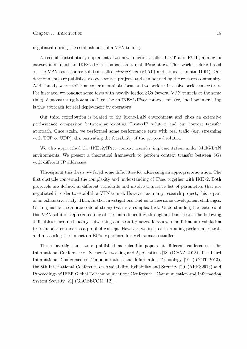
A second contribution, implements two new functions called GET and PUT, aiming to
extract and inject an IKEv2/IPsec context on a real IPsec stack. This work is done based
on the VPN open source solution called strongSwan (v4.5.0) and Linux (Ubuntu 11.04). Our
developments are published as open source projects and can be used by the research community.
Additionally, we establish an experimental platform, and we perform intensive performance tests.
For instance, we conduct some tests with heavily loaded SGs (several VPN tunnels at the same
time), demonstrating how smooth can be an IKEv2/IPsec context transfer, and how interesting
is this approach for real deployment by operators.
Our third contribution is related to the Mono-LAN environment and gives an extensive
performance comparison between an existing ClusterIP solution and our context transfer
approach. Once again, we performed some performance tests with real trafic (e.g. streaming
with TCP or UDP), demonstrating the feasability of the proposed solution.
We also approached the IKEv2/IPsec context transfer implementation under Multi-LAN
environments. We present a theoretical framework to perform context transfer between SGs
with different IP addresses.
Throughout this thesis, we faced some difficulties for addressing an appropriate solution. The
first obstacle concerned the complexity and understanding of IPsec together with IKEv2. Both
protocols are defined in different standards and involve a massive list of parameters that are
negotiated in order to establish a VPN tunnel. However, as in any research project, this is part
of an exhaustive study. Then, further investigations lead us to face some development challenges.
Getting inside the source code of strongSwan is a complex task. Understanding the features of
this VPN solution represented one of the main difficulties throughout this thesis. The following
difficulties concerned mainly networking and security network issues. In addition, our validation
tests are also consider as a proof of concept. However, we insisted in running performance tests
and measuring the impact on EU’s experience for each scenario studied.
These investigations were published as scientific papers at different conferences: The
International Conference on Secure Networking and Applications [18] (ICSNA 2013), The Third
International Conference on Communications and Information Technology [19] (ICCIT 2013),
the 8th International Conference on Availability, Reliability and Security [20] (ARES2013) and
Proceedings of IEEE Global Telecommunications Conference - Communication and Information
System Security [21] (GLOBECOM ’12) .

16 1.6. Thesis Organization
1.6 Thesis Organization
The remainder of the manuscript is composed of six chapters. Chapter 2 introduces all the
basic knowledge needed for a good understanding of the document. The description includes
IKEv2/IPsec protocols, and also introduces REDIRECT, MOBIKE and ClusterIP mechanisms.
Chapter 3 identifies the elements to be included in the IKEv2/IPsec context. We present
our initial results of GET and PUT functions, by illustrating the time it takes to recover an
IKEv2/IPsec session as well as the time for reinstalling the context again in the same gateway.
Chapter 4 and 5 are dedicated to the Mono-LAN architecture. First, we analyze how
ClusterIP (introduced in 1.3 and described in 2.5) improves the availability of a VPN service and
then we show some results of our test-bed. In addition, we observe the drawbacks and benefits of
this solution. Then, we define two architectures for IKEv2/IPsec environments: High Availability
and Traffic Management. We present our implementations through GET and PUT functions,
which are the heart of the IKEv2/IPsec context transfer.
In chapter 6, we address VPN platforms under Multi-LAN environments. We present a
theoretical solution allowing to perform context transfer between different SGs owning different
IP addresses. We show how the EU is impacted by the alteration of the IP address and how to
solve this issue as well as other factors.
Finally, chapter 7 includes the conclusions of our investigations and the future work, as well
as a description of the global evolution of the network concerning IPsec.

Part I
Security for IP Networks
17


Chapter 2
Roadmap of IPsec and IKEv2protocols
This chapter provides an overview of the services, protocols and mechanisms that are involved
in providing security based on IPsec and IKEv2. It also defines some mechanisms that provide
mobility and flexibility for IPsec/IKEv2, as well as some methods that allow management and
clustering at the IP layer. The goal of this theorical state of the art is to position most of
the mechanisms that were used during practical tests and are often mentioned through next
chapters.
2.1 Security Services
This section introduces some security services (also defined in [22]). Different protocols (e.g.
TLS, IPsec, Https) might offer these services at different layers of the OSI model.
� Data integrity: the property that data have not been altered or destroyed in an
unauthorized manner. In other words, during an IPsec-based communication, data
integrity allows verifying that the contents of an IP datagram were not changed, either
deliberately or due to random errors.
� Data origin authentication: the corroboration that the source of data received is as claimed.
It allows a node to verify that each incoming IP datagram was originated by the claimed
sender (source of data).
� Peer entity authentication: the corroboration that a peer entity in an association is
the one claimed. This service involves the identification and authentication of the peer.
Identification refers to an entity (user, equipment) claiming its identity by providing an
identifier (usually a name, pseudonym, IP address, domain name). Authentication consists
19

20 2.2. IPsec: Security Associations and Databases
in providing the claimed identity by providing one or several authentication elements,
known as credentials.
� Data confidentiality: the property that information is not made available or disclosed
to unauthorized individuals, entities or processes. As such, confidentiality transforms
data from an intelligible format (plaintext) to an unintelligible format (ciphertext). It
ensures that an unauthorized attacker or eavesdropper could not understand what is
being transmitted during IPsec-based communications, this reverse action is known as
decryption.
� Replay detection: consists for an entity to detect that received data are duplicated from a
previous exchange. Some data might have been sent in a secure manner by a legitimate
entity; but they can be copied and injected again to the same destination. Data are still
authentic but they are already processed several times.
� Access control: the prevention of unauthorized use of a resource, including the prevention
of use of a resource in an unauthorized manner. For IPsec, access control concerns a host
or a Security Gateway. Only authorized hosts or Security Gateways that are intended to
establish IPsec communications will be allowed to do so.
2.2 IPsec: Security Associations and Databases
IPsec is a protocol that proposes to secure any IP based communication by providing
security services (see 2.1). It is defined in [2]. IPsec offers interoperable, high quality and
cryptographically-based security for both Internet Protocol versions: IPv4 and IPv6. The most
common usage of IPsec consists in creating tunnels, often called Virtual Private Networks
(VPNs). Actually, IPsec is used to create trusted environments through unprotected networks.
When an entire network is being protected with IPsec, then tunnel mode is used. Otherwise,
when the communication exclusively takes place between two hosts, then transport mode is more
suitable. Figure 2.2 illustrates the scenarios where tunnel mode can be used, while figure 2.1
illustrates the transport mode scenario.
A Security Association (SA) is a data structure that contains security parameters to allow
instantiation of an IPsec communication. The set of SAs is stored in the Security Association
Database (SAD). Its goal is to offer security services for incoming/outgoing traffic it carries. As
a SA is unidirectional, two SAs are needed in order to protect both ways of a bidirectional
IPsec-based communication. In addition, some data are also stored in the Security Policy
Database (SPD). The SPD is consulted to define appropriate behavior facing incoming and
outgoing IP packets by specifying which traffic should be protected with IPsec or should bypass
IPsec. It is consulted for all inbound and outbound traffic. The SA relies on Authentication

Chapter 2. Roadmap of IPsec and IKEv2 protocols 21
Internet
IPsec Transport Mode
IPsec protected pathHost A Host B
Figure 2.1: IPsec transport mode scenarios.
Internet
IPsec Tunnel Mode
IPsec protected pathHost A Host B
(a) Endpoint to Endpoint Tunnel
Internet
IPsec Tunnel Mode
IPsec protected path
Host A
Host B
Protected SubnetIPsec Security
Gateway
Extremity of the tunnel Extremity of the tunnel
(b) Endpoint to Gateway Tunnel
Internet
IPsec Tunnel Mode
IPsec protected path
Host A
Protected SubnetIPsec Security
Gateway
Host B
Protected SubnetIPsec Security
Gateway
Extremity of the tunnel Extremity of the tunnel
(c) Gateway to Gateway Tunnel
Figure 2.2: IPsec tunnel mode scenarios.
Header (AH; see section 2.3.1) and Encapsulating Security Payload (ESP; see section 2.3.2)
protocols to offer its security services. Finally, all the parameters concerning SAD and SPD could
be configured manually by an administrator or could also be configured dynamically thanks to
the Internet Key Exchange Protocol (IKE). When IKE is used (which is mostly the case), an
additional database known as Peer Authorization Database (PAD) links each authorized identity
to its corresponding security parameters, thus, providing a link between IKE and each policy
stored in the SPD. Further details concerning IKE are explained in 2.4.
IPsec can be deployed under different scenarios. Depending on the concerned topology, IPsec
can be configured in two modes: transport mode or tunnel mode. Even if both modes use the
same techniques and algorithms to encrypt/decrypt, the difference relies on the encapsulation
and how a packet is built. Each mode has its own uses and thus it is important to care about
the selected one in order to run IPsec properly.

22 2.3. IPsec Protocols
ORIGINAL
IP HEADER PAYLOAD
NEW IP
HEADER
AH
HEADER PAYLOAD
ORIGINAL
IP HEADER
HASH
UNPROTECTED
PROTECTED
INTEGRITY PROTECTED
(a) Authentication Header in Tunnel Mode
ORIGINAL
IP HEADER PAYLOAD
ORIGINAL
IP HEADER
AH
HEADER PAYLOAD
HASH
UNPROTECTED
PROTECTED
INTEGRITY PROTECTED
(b) Authentication Header in Transport Mode
Figure 2.3: IPsec Encapsulation Protocol: Athentication Header
2.3 IPsec Protocols
2.3.1 Authentication Header
The Authentication Header (AH) is defined in [23]. It offers integrity, data origin authentication
and an optional anti-replay protection. The AH header (as in fig 2.3), serves to transport the
result of the integrity check over the entire original packet. As no encryption is performed,
Authentication Header does not ensure confidentiality and consequently has a much simpler
header than ESP. The AH header format depends on whether tunnel or transport mode is used.
Figure 2.3 shows in detail how the AH header is built when the original IP packet is being
protected using Authentication Header protocol in both transport and tunnel modes.
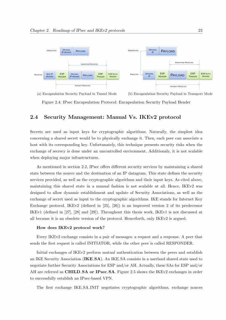
2.3.2 Encapsulation Security Payload
The Encapsulating Security Payload (ESP) protocol is defined in [24]. Depending on the
configuration parameters, ESP can offer confidentiality, data origin authentication, data integrity
and anti-replay services. The ESP header is more complex than the AH header. Figure 2.4 shows
in detail how the ESP fields are built using both transport and tunnel modes. Notice that ESP
not only adds a header between the IP header and the payload of the packet, but it also adds
some fields at the end of the packet. So the fact that ESP fields enclose the original payload,
makes security more complex than with AH which only adds an header.
Chapter 2. Roadmap of IPsec and IKEv2 protocols 23
ORIGINAL
IP HEADER PAYLOAD
NEW IP
HEADER PAYLOAD
ORIGINAL
IP HEADER
UNPROTECTED
PROTECTED ESP
HEADER
ESP
TRAILER
ESP AUTH
HEADER
INTEGRITY PROTECTED
ENCRYPTION PROTECTED
(a) Encapsulation Security Payload in Tunnel Mode
ORIGINAL
IP PAYLOAD
ORIGINAL
IP
ESP
HEADER PAYLOAD
UNPROTECTED
PROTECTED ESP
TRAILER
ESP AUTH
HEADER
INTEGRITY PROTECTED
ENCRYPTION PROTECTED
(b) Encapsulation Security Payload in Transport Mode
Figure 2.4: IPsec Encapsulation Protocol: Encapsulation Security Payload Header
2.4 Security Management: Manual Vs. IKEv2 protocol
Secrets are used as input keys for cryptographic algorithms. Naturally, the simplest idea
concerning a shared secret would be to physically exchange it. Then, each peer can associate a
host with its corresponding key. Unfortunately, this technique presents security risks when the
exchange of secrecy is done under an uncontrolled environment. Additionaly, it is not scalable
when deploying major infrastructures.
As mentioned in section 2.2, IPsec offers different security services by maintaining a shared
state between the source and the destination of an IP datagram. This state defines the security
services provided, as well as the cryptographic algorithms and their input keys. As cited above,
maintaining this shared state in a manual fashion is not scalable at all. Hence, IKEv2 was
designed to allow dynamic establishment and update of Security Associations, as well as the
exchange of secret used as input to the cryptographic algorithms. IKE stands for Internet Key
Exchange protocol. IKEv2 (defined in [25], [26]) is an improved version 2 of its predecessor
IKEv1 (defined in [27], [28] and [29]). Throughout this thesis work, IKEv1 is not discussed at
all because it is an obsolete version of the protocol. Henceforth, only IKEv2 is argued.
How does IKEv2 protocol work?
Every IKEv2 exchange consists in a pair of messages: a request and a response. A peer that
sends the first request is called INITIATOR, while the other peer is called RESPONDER.
Initial exchanges of IKEv2 perform mutual authentication between the peers and establish
an IKE Security Association (IKE SA). An IKE SA consists in a userland shared state used to
negotiate further Security Associations for ESP and/or AH. Actually, these SAs for ESP and/or
AH are referred as CHILD SA or IPsec SA. Figure 2.5 shows the IKEv2 exchanges in order
to successfully establish an IPsec-based VPN.
The first exchange IKE SA INIT negotiates cryptographic algorithms, exchange nonces

24 2.4. Security Management: Manual Vs. IKEv2 protocol
Figure 2.5: IKEv2 message exchanges, IKE INIT and IKE AUTH
and performs a Diffie-Hellman exchange. The following exchange IKE AUTH transmits
identities, demonstrates knowledge of the secret and negotiates the first CHILD SA (i.e. the
Security Association parameters). Only after both IKE SA INIT and IKE AUTH have been
acknowledged, further requests can be transmitted. The CREATE CHILD SA exchange allows
to create a new CHILD SA. And the INFORMATIONAL exchange allows to perform IKEv2
management tasks, like IP mobility, deletion of IKE SAs, liveness verification, among others.
2.4.1 Exchange Description: IKE SA INIT
This exchange helps to establish trust settings which ensure future IKE exchanges. Figure2.6
shows an graphic explanation of the IKE SA INIT request and response.
The INITIATOR sends the following information:
� SPI : security association unique identifier.
� Version Number : set to version 2 (e.g. IKEv2).
� SAi1 : cryptographic algorithms proposed.
� KEi1 : Diffie-Hellman values.
� Ni : INITIATOR’s nonce.

Chapter 2. Roadmap of IPsec and IKEv2 protocols 25
Figure 2.6: IKE SA INIT exchange details.
The responder replies with the following information:
� SPI : security association unique identifier.
� Version Number : set to version 2 (e.g. IKEv2).
� SAr1 : cryptographic algorithms chosen (based on proposition SAi1 ).
� KEr1 : Diffie-Hellman exchange.
� Nr : RESPONDER’s nonce.
� CERTREQ : if present, this optional field asks for a certificate.
At this point, both parties can generate a SKEYSEED, a shared secret from which all keys
are derived for that IKE SA. The first key, usually called SK e, is used for encryption. The
second one, for integrity, is called SK a. And finally, the SK d, is the key used to derive the keys
for the CHILD SAs (once again, keys for encryption and integrity protection).
2.4.2 Exchange Description: IKE AUTH
During the IKE AUTH exchange, both peers authenticate each other, and the first CHILD SA
is negotiated. Figure 2.7 illustrates the IKE AUTH exchange.

26 2.4. Security Management: Manual Vs. IKEv2 protocol
Figure 2.7: Detailed IKE AUTH exchange.
The INITIATOR sends the request with the following information:
� SPI : security association unique identifier.
� Version Number : set to version 2 (e.g. IKEv2).
� IDi : INITIATOR identity.
� CERT : INITIATOR certificate(s) (i.e. public key).
� CERTREQ : optionally ask for a certificate.
� IDr : optional RESPONDER identity to specify which of the responder’s identities it
wishes to talk to (i.e. a host running multiple identities).
� AUTH : a block of data protected with integrity protection (e.g. digital certificates or
pre-shared keys + ID )
� SAi2 : cryptographic algorithms proposed for the CHILD SA.
� TSi : defines the source address of the traffic forwarded from the INITIATOR of the
CHILD SA.
� TSr : defines the destination address of the traffic forwarded to the RESPONDER of the
CHILD SA.

Chapter 2. Roadmap of IPsec and IKEv2 protocols 27
The RESPONDER sends a response with the following information:
� SPI : security association unique identifier.
� Version Number : set to version 2 (e.g. IKEv2).
� IDr : confirms identity by sending the RESPONDER’s identity (IDr).
� CERT : RESPONDER certificate with the public key to verify the AUTH field.
� AUTH : all information which is used to perform integrity protection.
� SAr2 : cryptographic algorithms selected for the CHILD SA.
� TSi : defines the source address of the traffic forwarded from the INITIATOR of the
CHILD SA.
� TSr : defines the destination address of the traffic forwarded to the RESPONDER of the
CHILD SA.
2.4.3 Authentication of IKE SA
The authentication of the IKE SA could be achieved in three different manners: Pre-shared keys,
X.509 Certificates or EAP (Extensible Authentication Protocol).
The easiest method to configure and authenticate IKE SAs is the pre-shared key, where both
entities keep the same secret in a secure place. Security risks might be the main drawback of
this authentication method due to the difficulty to keep the ”shared” secret in a safe place. Also,
the shared secret must be distributed among the entities that comunicate, which also represent
a risk.
The authentication through certificate X.509 is another way to authenticate endpoints but
demands a more complex system. The X.509 certificates use an algorithm based on assymetric
cryptography. This method uses two cryptographic keys per user: a public key and a private key.
The certificate authority certifies that both keys are unique per user and are properly linked.
Depending on how these keys are used, the user can ensure integrity protection of the message
as well as the identity of the sender. The sender signs the data using its private key and sends
it to other users. Thanks to this signature, all recipients can verify the integrity and identity of
the message by using the public key of the sender.
However, there are scenarios where the pre-shared key method does not scale well or the
distribution of certificates X.509 is too complicated for the administrator (E.g. too much users).
Thus, EAP-IKEv2 protocol consists in other way to perform authentication. EAP-IKEv2 uses
an additional exchange towards an authenticator EAP server to authenticate endpoints. Details
of EAP with IKEv2 can be found in [30].

28 2.5. Clustering at the IP layer: ClusterIP
2.5 Clustering at the IP layer: ClusterIP
ClusterIP is an implementation based on recent Linux kernels (2.6 and higher). It permits
load-balancing features without having a physical load-balancer. It is a smooth way to distribute
the load of incoming IP packets in a very autonomous manner (each node can decide whether
it is responsible or not for each incoming IP packet).
However, let us first introduce the notion of a cluster. In a computer system, a cluster is a
group of servers and resources that act like a single system. These are commonly used to offer
high availability, parallel processing or load balancing. Cluster members may exchange some
data in order to be able to offer these features.
Under Linux kernel distributions, iptables is an implementation which configures, maintains,
and inspects firewalling rules. It identifies an IP packet that matches a defined rule. This action
is called target. ClusterIP is an extended target module of iptables, allowing to build a cluster of
machines that share a common IP address without having a physical machine that performs this
task. Indeed, ClusterIP is intended to provide load-balancing and clustering features without
having a dedicated load-balancer machine. Thus, ClusterIP consists in a loadbalancer-less cluster
on Linux operative system. It simply enables a server to calculate responsibility of incoming IP
packets so that the server can decide by itself either it has to treat it or not.
When using a ClusterIP approach, no special hardware is required to benefit from its
load-balancing and clustering features. The configured members of the cluster share a common
multicast MAC address and thus receive the same packets. Then, a lower-layer mechanism
(ClusterIP) filters packets at the IP layer by calculating responsibility through an algorithm
(E.g. hashing the IP source of each packet). When used in command line interface, ClusterIP is
a parameter of the iptables command.
The following parameters are set when implementing ClusterIP:
� –new: creates a new cluster. Must be the first rule in the list of rules.
� –hashmode mode: mode of hashing. Must be one of the following: sourceip,
sourceip-sourceport, sourceip-sourceport-destport.
� –clustermac mac: multicast MAC address of the cluster.
� –total-nodes num: total number of nodes within this cluster.
� –local-node num: the id number of the local node within the cluster.
� –hash-init rnd: a random seed for hash initialization.

Chapter 2. Roadmap of IPsec and IKEv2 protocols 29
The nodes in a cluster usually have two Network Interface Card (NIC). One of the NIC’s
MAC address is replaced by the shared cluster MAC address and then a common virtual IP
address is mapped onto it. The other NIC, being completely independent, can be used for any
other purpose, as for example inter-nodes communications (E.g. Hearbeat mechanism, keep
alives, etc.). Given the case where a machine counts with only one NIC, it is also possible to
install a second virtualized IP address on the same interface.
Originally, ClusterIP does not handle IPsec traffic. However, if an IKE daemon (E.g
strongSwan) handles to synchronize IKE SAs states and basic IPsec SAs states, a modified
version of ClusterIP that handles IPsec traffic could solve synchronization troubles. The overhead
for synchronizing ESP sequence numbers is elevated due to the fact that ESP sequence counters
grow too quickly. Deploying IKE and IPsec in a cluster requires the synchronization of some
information among all the cluster members. Synchronizing counters might be the major barrier
to overcome when it comes to setting up a cluster with IPsec.
2.6 MOBIKE - mobility extension for IKEv2
MOBIKE stands for IKEv2 Mobility and Multihoming (MOBIKE) Protocol. It is an extension
to IKEv2 protocol. MOBIKE allows to change the IP address associated to an IKEv2/IPsec
tunnel.
Originally, IKEv2 and IPsec states were designed more likely to be static. IPsec/IKEv2 data
was supposed to remain the same during an IPsec session or VPN Tunnel establishment. For
example, if a node that initially established an IPsec tunnel changes its original IP address (E.g.
it change its point of attachment and changes its IP address), the node was forced to brake down
its connection and to re-initialize a new IPsec tunnel from scratch with the new IP address.
MOBIKE allows to update the IPsec SAs (SPD, SAD and PAD) and IKE SAs (information
contained in the IKEv2 application). Both peers need to agree on MOBIKE protocol support at
the begging, which is is done during IKE AUTH exchange of IKEv2 (see figure 2.8). When lower
layers detect that a new IP address is present in the currently used interface, the peer updates its
IKEv2/IPsec databases and it sends an INFORMATIONAL message including a notify payload
UPDATE SA ADDRESSES. When the other peer receives this message, it updates its IPsec SAs
and IKE SAs as well.
MOBIKE also offers some multihoming features. It allows to built, under priority order, a list
of IP addresses where an endpoint is reachable. When connection is lost through the currently
used IP address, the other endpoint can reach the peer through the second IP address on the
list, then the third, and so on. Servers with more than one network interface can offer this
feature. The notify payload which agreggates an IP address is ADDITIONAL IP4 ADDRESS

30 2.7. REDIRECT extension for IKEv2
I n i t i a t o r (MN) Responder (SG)−−−−−−−−−−−−−−−−−−−−−−−−−−−−−−−−−−−−−−−−−−−−−−−−−−−−−−−−−−−−−−−−−−
IKE AUTH ( IP I1 :4500 −> IP R1 :4500 )HDR, SK { IDi , CERT, AUTH,
CP(CFG REQUEST) ,SAi2 , TSi , TSr ,N(MOBIKE SUPPORTED)} −−>
<−− ( IP R1 :4500 −> IP I1 : 4500 )HDR, SK { IDr , CERT, AUTH,CP(CFG REPLY) ,SAr2 , TSi , TSr ,N(MOBIKE SUPPORTED) }
.
.
.( IP I2 :4500 −> IP R1 :4500 )
IP mob i l i ty HDR, SK { N(UPDATE SA ADDRESSES) ,occurs N(NAT DETECTION SOURCE IP) ,
N(NAT DETECTION DESTINATION IP) } −−>
<−− ( IP R1 :4500 −> IP I2 : 4500 )HDR, SK { N(NAT DETECTION SOURCE IP) ,N(NAT DETECTION DESTINATION IP) }
Figure 2.8: MOBIKE Protocol Exchanges
I n i t i a t o r (MN) Responder (SG)−−−−−−−−−−−−−−−−−−−−−−−−−−−−−−−−−−−−−−−−−−−−−−−−−−−−−−−−−−−−−−−−−−−HDR, SAi1 , KEi , NiN(REDIRECT SUPPORTED)−−>
<−− HDR, N(REDIRECT, New GW ID, Ni data )
Figure 2.9: REDIRECT support during IKE SA INIT
or ADDITIONAL IP6 ADDRESS whether it is an IPv4 or IPv6 address. If no additional IP
address exists, then a notify payload NO ADDITIONAL ADDRESSES is sent.
2.7 REDIRECT extension for IKEv2
The REDIRECT mechanism is an extension of the Internet Key Exchange protocol (IKEv2)
defined in [4]. It allows a Security Gateway to redirect the traffic flow to another Security
Gateway (SG). Therefore, if a SG is being shut down for maintenance, it is possible to
REDIRECT the VPN clients to another SG.
A peer can explicitly inform the other peers that it supports the REDIRECT mechanism by
adding a notify payload during an IKE SA INIT or INFORMATIONAL exchange. Figure 2.9
shows the details during an exchange.

Chapter 2. Roadmap of IPsec and IKEv2 protocols 31
I n i t i a t o r (MN) Responder (SG)−−−−−−−−−−−−−−−−−−−−−−−−−−−−−−−−−−−−−−−−−−−−−−−−−−−−−−
<−− HDR, SK {N(REDIRECT, New GW ID)}
HDR, SK {} −−>
Figure 2.10: REDIRECT exchanges
Figure 2.10 illustrates a REDIRECT exchange during an active session. The Mobile Node
(MN) receives the INFORMATIONAL message with the correspondent notify payload and the
new security gateway ID (i.e. IPv4, IPv6 or FQDN).
2.8 Conclusion
ISPs are mainly using IPsec Virtual Private Networks (VPNs) to extend a security domain over
untrusted networks. End-Users may secure their communications with theirs ISPs by establishing
an IPsec tunnel with a Security Gateway. Hence, ISPs are called to offer higly reliable services
with IPsec Security Gateways. On the other hand, an operator might want to migrate an IPsec
session from one SG to another for several reasons (e.g. offload, mobility, failure predictive
actions, avoid re-authentication, cloud service topologies, among others).
Considering the evolution of mobile networks through the past ten years, ISPs need to face
new challenges in terms of security. EUs are increasingly prone to mobility or multihoming
operations. In addition, the new cloud services introduce more challenges in order to offer better
QoS, as well as high availability to those contents that the EUs want to access wherever they
need to.
Throughout this chapter, we introduce the notions of IPsec. Two entities wishing to establish
a secure communication, may use the IPsec suite together with the IKEv2 protocol in order to
authenticate and encrypt their exchanges.
Further explanations introduce some mechanisms that addresses new challenges facing
mobility, multihoming and clustering at the IPsec layer. For example, we briefly introduce
ClusterIP (see 2.5), REDIRECT (see 2.7) and MOBIKE (see 2.6) exentions, which improves
the performances facing mobility, overload and multihoming issues of IKEv2/IPsec tunnels.
Finally, these mechanisms are also extensively discussed later in chapter 6.

32 2.8. Conclusion

Chapter 3
IKEv2/IPsec Context Definition
3.1 Introduction
Operators are mainly using IPsec Virtual Private Networks (VPNs) to extend a security
domain over untrusted networks. A VPN is usually established when an End-User (EU) and a
Security Gateway (SG) negotiate some parameters referred as Security Associations (SA). For
a better QoS, these SGs are geographically distributed so they are as close as possible to EU.
As such, the higher is the level of responsibility of a SG, the higher is the risk to be overloaded
and to break down.
This chapter introduces the definition of an IKEv2/IPsec context. When two nodes establish
an IKEv2/IPsec-based communication or VPN, a set of parameters are agreed by both
extremities of the VPN. In order to secure their IP traffic, some cryptographic information
is built on both sides of the tunnel.
Initial exchanges first agree on a secure channel also called IKE security association
(IKE SA). This IKE channel permits IPsec entities to negotiate and maintain some security
parameters known as IPsec Security Associations (IPsec SA). An IPsec SA consists in some
shared information used to secure the IP communications between both extremities of a VPN.
Throughout this chapter, we will also present our investigations related to the extraction
(commonly cited as GET) and re-installation (referred as PUT) of an IKEv2/IPsec context.
Notice that both the IKE SA and the IPsec SA are referred together as IKEv2/IPsec context,
which is simpler an easier for readers. On the other hand, all the developments of our
implementation are done within strongSwan, which is an open source VPN software for Linux
environments.
This chapter introduce a mechanism for extracting and reinstalling security associations
(both IKE SA and IPsec SA), as well as a mechanism to transfer a given IPsec traffic from one SG
33

34 3.2. Motivation
to another. We also propose an additional mechanism for solving the mis-synchronization of IPsec
anti-replay counters and IKEv2 Messages ID counters. Finally some performance measurements
are provided in terms of delays, and packet loss, and prove feasibility of the approach.
Section 3.3 describes details of an IKEv2/IPsec context. Section 3.4 introduces a proposed
mechanism to perform IPsec Context Transfers (referred to as IPsec-CXT), a description of
GET and PUT functions and a step-by-step description of an IPsec-CXT. Finally, sections 3.4.2
and 3.5 describe our implementation as well as the testbed results.
3.2 Motivation
IPsec provides a security framework at the network layer allowing IP and upper-layer protocols
to benefit from encrypted and authenticated communications. They are mostly used to secure
peer-to-gateway or gateway-to-gateway communications (see 2.1 and 2.2), or VPN (Virtual
Private Networks). When providing VPN services based on IPsec, an End-User (EU) commonly
makes use of the IKEv2 protocol [26] to negotiate IKEv2 security associations (IKE SAs) and
further IPsec security associations (IPsec SAs) towards a security gateway (SG). Figure 2.5
illustrates the tunnel establishment and different exchanges.
In order to reduce delays and improve communications, the path between an EU and the SG
should be as short as possible. As such, operators may rely on geographically distributed pool
of SGs to provide a high QoS. On the other hand, an operator that offers fail-over capacities
should be able to transfer VPN sessions from one SG to another. Motivation may be to spread the
workload among different SGs, as well as to provide high availability features in case a SG fails.
The scenario we are considering is an EU that sets up a VPN towards an SG (e.g. SG1) which
gives access to a trusted network. The EU is first authenticated by using IKEv2 protocol with
either pre-shared keys, EAP-AKA, EAP-SIM, certificates, etc. Then, further IKEv2 exchanges
allow to set up the VPN (i.e. IKE SAs and IPsec SAs). At a given time, SG1 is overloaded,
whereas some other SGs are not (e.g. SG2). The operator wants to move this VPN session from
SG1 towards SG2, so it transfers all the IKEv2/IPsec context. The main goal of transferring all
IKEv2/IPsec context is to avoid re-authentication against SG2. In fact, re-authentication would
increase signaling and would interrupt the communication which could be critical for real-time
based applications. Note that if SG1 and SG2 do not have the same IP address, then the EU
MUST also update its IKE SAs and IPsec SAs. Transferring the IKEv2/IPsec context introduces
the following constraints: (1) identification of the IKEv2/IPsec parameters so it can be extracted
and reinstalled into another SG. Notice that some parameters of the context requires perfect
timing, which is much more difficult to get than the IKEv2/IPsec context itself, (2) two gateways
with different IP addresses bring complexity as the hosts should consider the management of
their tunnel and their SAs (mobility aspect), as well as the distance between SGs introduces
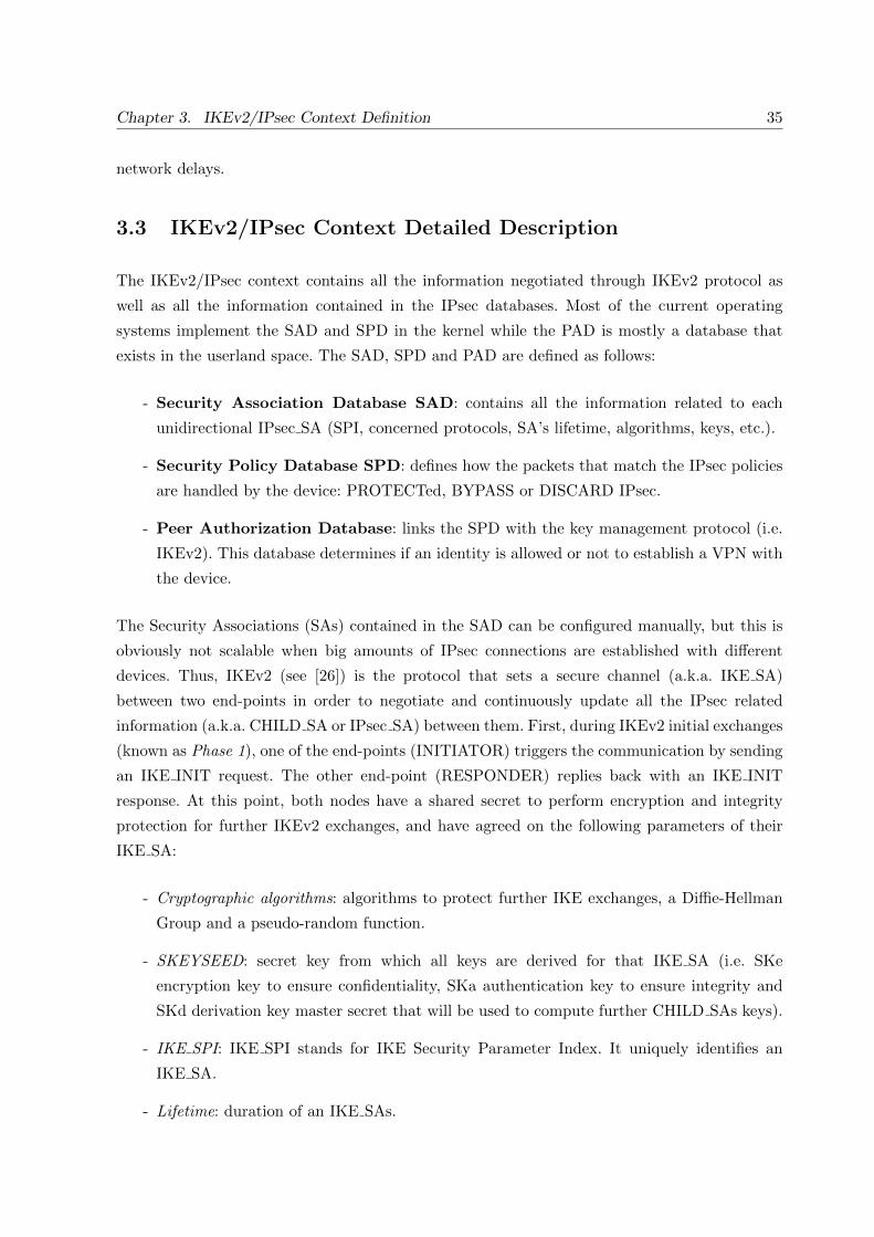
Chapter 3. IKEv2/IPsec Context Definition 35
network delays.
3.3 IKEv2/IPsec Context Detailed Description
The IKEv2/IPsec context contains all the information negotiated through IKEv2 protocol as
well as all the information contained in the IPsec databases. Most of the current operating
systems implement the SAD and SPD in the kernel while the PAD is mostly a database that
exists in the userland space. The SAD, SPD and PAD are defined as follows:
- Security Association Database SAD: contains all the information related to each
unidirectional IPsec SA (SPI, concerned protocols, SA’s lifetime, algorithms, keys, etc.).
- Security Policy Database SPD: defines how the packets that match the IPsec policies
are handled by the device: PROTECTed, BYPASS or DISCARD IPsec.
- Peer Authorization Database: links the SPD with the key management protocol (i.e.
IKEv2). This database determines if an identity is allowed or not to establish a VPN with
the device.
The Security Associations (SAs) contained in the SAD can be configured manually, but this is
obviously not scalable when big amounts of IPsec connections are established with different
devices. Thus, IKEv2 (see [26]) is the protocol that sets a secure channel (a.k.a. IKE SA)
between two end-points in order to negotiate and continuously update all the IPsec related
information (a.k.a. CHILD SA or IPsec SA) between them. First, during IKEv2 initial exchanges
(known as Phase 1), one of the end-points (INITIATOR) triggers the communication by sending
an IKE INIT request. The other end-point (RESPONDER) replies back with an IKE INIT
response. At this point, both nodes have a shared secret to perform encryption and integrity
protection for further IKEv2 exchanges, and have agreed on the following parameters of their
IKE SA:
- Cryptographic algorithms: algorithms to protect further IKE exchanges, a Diffie-Hellman
Group and a pseudo-random function.
- SKEYSEED: secret key from which all keys are derived for that IKE SA (i.e. SKe
encryption key to ensure confidentiality, SKa authentication key to ensure integrity and
SKd derivation key master secret that will be used to compute further CHILD SAs keys).
- IKE SPI: IKE SPI stands for IKE Security Parameter Index. It uniquely identifies an
IKE SA.
- Lifetime: duration of an IKE SAs.

36 3.3. IKEv2/IPsec Context Detailed Description
- Nonces: the INITIATOR nonce and RESPONDER nonce (Ni and Nr) are randomly
generated values which reinforce the security by refreshing the key material.
- Message ID counters: the ID counters provide anti-replay for IKEv2 exchanges by
increasing the ID counter by one for every emitted IKEv2 message.
- IKEv2 window size: if the window size has a value of ”N”, it implies that there can be N
un-acknowledged IKEv2 requests at any given time during communication.
During the Phase 2 of IKEv2, the INITIATOR sends a IKE AUTH request and the
RESPONDER replies with an IKE AUTH response. Now, the nodes consult their PAD in order
to authenticate each other. As mentioned, the PAD determines if the identity of a given node is
allowed or not to establish a CHILD SA. The PAD is composed of the following information:
- Identifiers: IDi (INITIATOR ID) and IDr (RESPONDER ID). Usually an IPv4/IPv6
address, a fully-qualified domain name, an email address,etc.
- Authentication Method: pre-shared key, EAP, certificates, RSA, etc.
The establishment of the CHILD SA (negotiation of parameters stored in the SAD and SPD)
is piggybacked during the IKE AUTH exchange. It is done just once the authentication and
the authorization are performed. When Phase 2 is done, both nodes agree on the following
parameters of their CHILD SAs:
Concerning the SAD
- CHILD SA SPI: a 32 bits unique identifier of the CHILD SA.
- IP addresses: source/destination IP addresses of the IKEv2 compliant nodes.
- IPsec Protocol: AH (Authentication Header) or ESP (Encapsulating Security Payload).
- Sequence number counter: value to control every incoming/outgoing IP packet protected
with IPsec, preventing replay or unauthorized re-injection of already processed IPsec
traffic.
- Anti-replay window size N: any packet with the sequence number X + N is discarded,
where X is the awaited sequence number.
- ESP/AH information: Encryption and/or authentication algorithms, keys, initialization
values, key lifetimes.
- Lifetime: time interval or byte count after which a SA must be replaced with a new SA
(and new SPI).

Chapter 3. IKEv2/IPsec Context Definition 37
- IPsec Protocol Mode: tunnel or transport mode.
- Path MTU: maximum size of an IPsec packet that can be transmitted without
fragmentation.
Concerning the SPD
- IPsec Protocol Mode: tunnel or transport mode.
- Header’s IP Address: source/destination IP addresses of the IKEv2 compliant nodes.
- Source/Destination IP addresses of the communications: if transport mode is being used,
these addresses are the same as those used for routing purposes, whereas in tunnel mode
these IPs concern the end-points of the communications (which could be an internal IP
address of a protected subnet).
- Upperspec: upper-layer protected protocol (HTTP, FTP, HTTPS, among others).
- Policy rules: DENY, BYPASS or PROTECT the targeted traffic.
3.4 GET and PUT functions: Description
3.4.1 Motivation: manage and transfer of and IKEv2/IPsec context
We propose a framework (fig. 3.1) to dynamically manage an IKEv2/IPsec context. New features
are introduced in section 3.4.2 (GET and PUT). This framework proposes to extract and
re-install an IKEv2/IPsec context from one SG to another, which we refer as IPsec-CXT (IPsec
context transfer). The IPsec-CXT between two SGs can be performed with CXTP protocol (see
[7]), mobility operations (e.g. MOBIKE) or with REDIRECT extension of IKEv2. However we
will first concentrate in just extracting and re-installing the IKEv2/IPsec context before its
transfer. The transfer of an IKEv2/IPsec context is discussed in detail in chapter 4 and 6.
In order to improve the management of an IKEv2/IPsec , we initially define two operations:
GET and PUT. GET extracts the IKEv2/IPsec context for a given tunnel, whereas PUT
makes installation of it. Details of an IKEv2/IPsec context are described in [18].
3.4.2 Implementation
Our implementation is based on StrongSwan 4.5.0 [16], a widely used IKEv2 open-source
implementation for linux environments. Its multi-threading design meets today’s requirements.
As IPsec is a complex protocol, strongSwan has a very modular style. A daemon called starter
initializes the IPsec framework and launches the different daemons defined through configuration
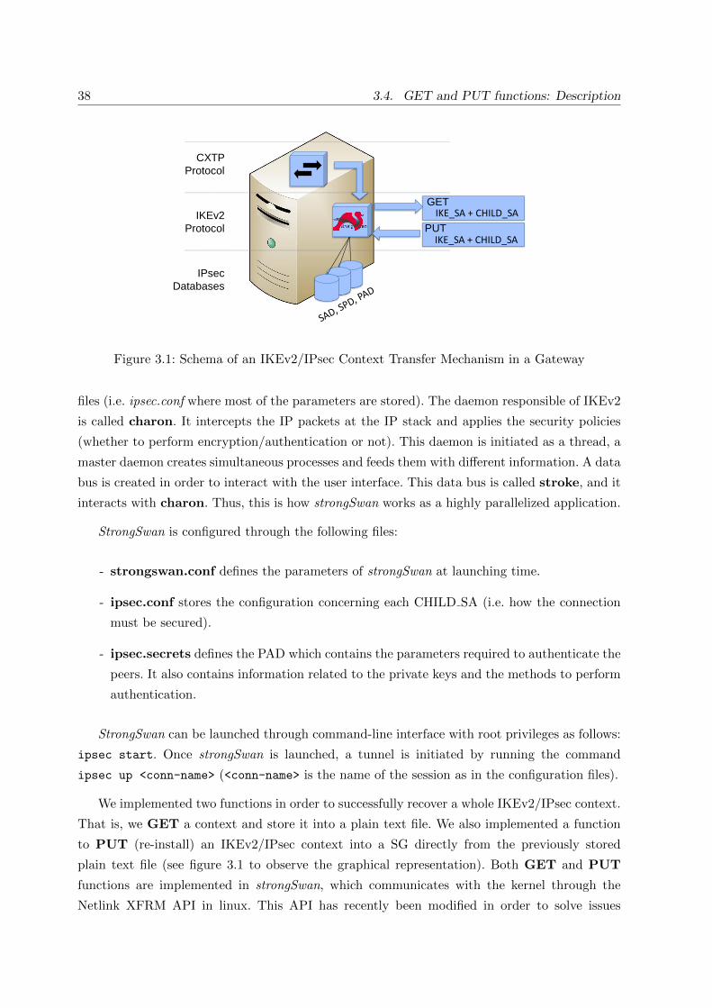
38 3.4. GET and PUT functions: Description
IPsec
Databases
CXTP
Protocol
IKEv2
Protocol
GET
PUT
IKE_SA + CHILD_SA
IKE_SA + CHILD_SA
Figure 3.1: Schema of an IKEv2/IPsec Context Transfer Mechanism in a Gateway
files (i.e. ipsec.conf where most of the parameters are stored). The daemon responsible of IKEv2
is called charon. It intercepts the IP packets at the IP stack and applies the security policies
(whether to perform encryption/authentication or not). This daemon is initiated as a thread, a
master daemon creates simultaneous processes and feeds them with different information. A data
bus is created in order to interact with the user interface. This data bus is called stroke, and it
interacts with charon. Thus, this is how strongSwan works as a highly parallelized application.
StrongSwan is configured through the following files:
- strongswan.conf defines the parameters of strongSwan at launching time.
- ipsec.conf stores the configuration concerning each CHILD SA (i.e. how the connection
must be secured).
- ipsec.secrets defines the PAD which contains the parameters required to authenticate the
peers. It also contains information related to the private keys and the methods to perform
authentication.
StrongSwan can be launched through command-line interface with root privileges as follows:
ipsec start. Once strongSwan is launched, a tunnel is initiated by running the command
ipsec up <conn-name> (<conn-name> is the name of the session as in the configuration files).
We implemented two functions in order to successfully recover a whole IKEv2/IPsec context.
That is, we GET a context and store it into a plain text file. We also implemented a function
to PUT (re-install) an IKEv2/IPsec context into a SG directly from the previously stored
plain text file (see figure 3.1 to observe the graphical representation). Both GET and PUT
functions are implemented in strongSwan, which communicates with the kernel through the
Netlink XFRM API in linux. This API has recently been modified in order to solve issues

Chapter 3. IKEv2/IPsec Context Definition 39
concerning the IPsec replay sequence counters synchronization. Netlink XFRM allows to modify
these counters at any time in order to synchronize them. This feature is very useful when
clustering security gateways. On the other hand, the lookup of the IKE SA and CHILD SA
inside strongSwan is done through its connection name (we refer to it as ”<conn-name>” in
the examples): the command ipsec get <conn-name> performs GET whereas the command
ipsec put <conn-name> performs PUT.
- ipsec get <conn-name>: The command ipsec is intercepted by the strongSwan daemon.
The command get launches the function that recovers the IKE SA + PAD + CHILD SA.
The lookup of the IKE SA and its corresponding CHILD SA is done through its name
”<conn-name>”. Finally, it creates a plain text file in the temporary directory (/tmp/)
with all the information.
- ipsec put <conn-name>: The command ipsec is intercepted by the strongSwan daemon.
The command put launches the function that installs the IKEv2/IPsec recovered context
from a plain text file. The IKE SA and CHILD SA are introduced in strongSwan with the
name:”<conn-name>”.
3.4.3 Testbed
Our platform is composed of two desktop stations. Both operating systems run over Ubuntu
(v12.04LTS in the IPsec EU, and v11.10 in the SG). Our tests are performed locally on the
same SG and permit to test the interaction with the IPsec stack.
First of all, we focused on measuring the time to establish a single VPN session towards a
SG. Then, we increment the number of VPN session to perform load tests on the platform. We
also measure how an interruption of service at the IPsec layer impacts upper-layers transmissions
(like HTTP). For example, refer to figure 3.5a to see in details all the exchanges while performing
GET and PUT at the IPsec layer during and HTTP download. We focus in studying the impact
of this interruption. Tests are performed with HTTP traffic over Ethernet links.
The results are represented in graphs with a box-and-whiskers style (also called quartiles).
This kind of representation is mostly used to plot statistical data. For every measurement
made (around 100 samples per measure), the box-and-whisker figure indicates: (i) the smallest
observation, (ii) the lower quartile, (iii) the upper quartile, (iv) the largest observation and (v)
the median. The space between the lower and upper quartile represents 50% of the samples (see
figure 3.2).
During the tests, we used Traffic Control in order to vary the bandwidth limit during the HTTP
download and thus study the impact over different transmission rates. To generate statistical
results, 100 measurements were done.

40 3.5. Performance tests & Results
(i) smallest observation
(ii) lower quartile
(iii) upper quartile
(iv) largest observation
(v) the median
Figure 3.2: Box-and-Whisker plot representation (quartiles)
The tests have been measured by using the command time, which writes a message to
standard output giving timing statistics about this program run. The outputs of time are (i)
the elapsed real time between invocation and termination of the command, (ii) the user CPU
time and (iii) the system CPU time. We considered the value of the elapsed real time in order to
evaluate our stats results. For simplicity, we will refer to elapsed real time as time. This is how
we measured the time it takes for a given command to run.
3.5 Performance tests & Results
The different testbed measurements are performed over Ethernet links (some of them with
different bandwidths). We load the SG by establishing different numbers of VPN tunnels for
each TCP connection granulated by its port number. For example, a TCP connection using port
80 will not traverse the same tunnel as a TCP connection using port 81. They will use different
cryptographic material and thus different IKEv2/IPsec tunnels.
3.5.1 First Test - VPN Establishment Time
The first test measures the time for establishing IKEv2/IPsec tunnels between two end-points
(see figure 3.3). The tunnels were initiated one after the other to avoid half-opened IKE-SAs.

Chapter 3. IKEv2/IPsec Context Definition 41
0.3
0.35
0.4
0.45
0.5
0.55
0.6
0.65
0.7
0.75
0.8
0.85
0.9
0.95
1
10 100 200
300 400
500 600
700 1000
Tim
e to s
et a V
PN
(s)
Number of Virtual Private Networks
Figure 3.3: VPN Establishment Time
This is not a stress test but a load test. Figure 3.3 gives the results for initializing 10, 100, 200,
300, 400, 500, 700 and 1k tunnels. We can clearly see that the time measured is proportionally
higher as the amount of VPNs rises. Establishment of 10 tunnels takes 0.31s to 0.41s, whereas
1000 tunnels may take 0.89s up to 1s for a single VPN establishment. All the other measures
(i.e. 100, 200, 300 tunnels ...) show results between 0.3s and 1s for a single VPN establishment.
3.5.2 Second Test - GET and PUT Times
Our second test consists in measuring the time to GET and to PUT an active IKEv2/IPsec
context. First, we established different scenarios (different amount of active tunnels): 10, 20, 30,
40, 50, 60, 70 , 100, 200, 300, 400, 500, 600, 700 and 1k active VPN tunnels. Then, we proceed to
GET ten (10) randomly chosen VPNs over each scenario (10,100,200...). The resulting time to
GET 10 randomly chosen VPNs is divided by 10 in order to obtain the average time to perform
a GET over a single VPN connection. Detailed results are shown in figure 3.4a. We can observe
that the values are quite similar for all the scenarios (we consider the case of 10 and 30 VPNs
isolated variations, which is normal). The command ipsec get performs its task in a range of
5ms up to 15ms. By the way, by observing figure 3.4a we can realize that a loaded SG (600-700
VPNs) takes more likely 13ms-15ms to perform a GET over a single VPN whereas for a not
loaded SG these times are around 5ms up to 12ms. This dispersion can be explained due to the
semaphores for controlling access to an IKE SA. This means that an IKE SA can be in use by
any process within strongSwan, and thus increasing the time to GET the desired IKE SA.

42 3.5. Performance tests & Results
4
5
6
7
10
11
12
13
14
15
20
10 20 30 40 50 60 70 100200
300400
500700
1000
Tim
e t
o
GE
T a
VP
N (
ms)
Number of VPNs
10 V
PN
s
20 V
PN
s
30 V
PN
s
40 V
PN
s
50 V
PN
s
60 V
PN
s
70 V
PN
s
100 V
PN
s
200 V
PN
s
300 V
PN
s
400 V
PN
s
500 V
PN
s
600 V
PN
s
700 V
PN
s
Get_Time-quartile
(a) GET Test
2
4567
101112131415
20
22
10 20 30 40 50 60 70 80 90 100200
300400
500600
7001000
Tim
e to P
UT
a V
PN
(m
s)
Number of VPNs
10
VP
Ns
20
VP
Ns
30
VP
Ns
40
VP
Ns
50
VP
Ns
60
VP
Ns
70
VP
Ns
80
VP
Ns
90
VP
Ns
10
0 V
PN
s
20
0 V
PN
s
30
0 V
PN
s
40
0 V
PN
s
50
0 V
PN
s
60
0 V
PN
s
70
0 V
PN
s
10
00
VP
Ns
(b) PUT Test
Figure 3.4: Experimental IKEv2/IPsec Context Management

Chapter 3. IKEv2/IPsec Context Definition 43
IKE_INIT
@EU
TIM
E
IPsec Gateway
@SG1
IKEv2/IPsec Tunnel @EU-@SG1
IKE_AUTH
HTTP
Do
wn
load
w
get
ESP
ESP
ESP IPsec G
ET
ESP
ESP
ESP
X X X
IPsec P
UT
IKEv2/IPsec Tunnel @EU-@SG1
ESP
ESP
IPsec Peer
(a) Detail of the test
25
30
35
40
45
50
55
60
65
70
100 500 1000
2000 3000
5000 10000
Seconds
Download Rate in kB/s
(b) Dowload Time with TS=10s
60
80
100
120
140
160
180
100 500
1000 2000
3000 5000
10000
Seconds
Download Rate in kB/s
(c) Dowload Time with TS=30s
100
120
140
160
180
200
220
240
100 500
1000 2000
3000 5000
10000
Seconds
Download Rate in kB/s
(d) Dowload Time with TS=60s
Figure 3.5: Upper-layer’s Reactivity
Then, we proceed to PUT these ten (10) previously randomly chosen VPNs for each scenario
(10,100,200...). The time that the script takes to PUT these connections is divided by ten (10).
This results in the average time to PUT a single VPN active session. Figure 3.4b shows the
measurements concerning the PUT function for all the scenarios. It represents the time that a
SG takes to install a single IKEv2/IPsec context from a file. We observe that strongSwan takes
a range of 2ms up to 22ms to perform a PUT of a single VPN.
3.5.3 Third Test - Upper-layer’s Reactivity
We observed the reactivity of upper-layer protocols facing interruptions at the IPsec layer on SG’s
side. The test consists to GET and PUT a single VPN connection during an HTTP download.
We perform this with different traffic rates (controlled with Traffic Control implementation for

44 3.6. How can we transfer an IKEv2/IPsec context?
linux [31]). Figure 3.5a illustrates a protocol representation of what happens during this test.
Initially, a VPN is established between an EU and the SG. Then, we start an HTTP download by
using the command wget. The source file is placed on the EU’s side whereas the SG is configured
as the destination. Even if in real life, an EU (and not the SG) is usually the destination when
downloading files from the Internet, we chose this methodology in order to analyze the impact
of a SG facing interruptions at the IPsec layer. Thus, after the download has been performed
during five (5) seconds, we GET the whole IKEv2/IPsec context on the SG, causing it to loose
connectivity with the peer. The EU continues to send ESP packets as it is unaware of the GET
function performed on the SG side. We considered different interruption times (TS Time Sleeps
of 10, 30 and 60 seconds) before performing a PUT function. Finally, once the IKEv2/IPsec
context is reinstalled, we observed the time to finish the HTTP download. As we carry HTTP
traffic over an IPsec protected communication, we set the HTTP parameters through wget to
be as flexible as possible facing interruptions. Also, as we measured different traffic rates during
the downloads, we changed the size of the file being downloaded (because big size files would
take too much time to download at lower rates). Table 3.1 shows the different file sizes used for
each traffic rate. Figure 3.5 represents the download time concerning all file sizes and rates. Each
Table 3.1: Third Test - Interruption Times, Traffic Rate and File Sizes
Interruption Rate FileTime TS Size
10 kB/s 1MB100 kB/s 5MB
10s, 30s 500 kB/s 20MBand 60s 1 MB/s 20MB
2 MB/s 20MB3 MB/s 100MB5 MB/s 100MB10 MB/s 100MB
figure ( 3.5b, 3.5c and 3.5d) shows the download times for each interruption TS . We observe that
at lower traffic rates (less than 3000kB/s), the measures are very stable because the quartiles
are very thin. For higher traffic rates (more than 3000kB/s), the download time is unstable and
so the quartiles are more spread and thicker. On the other hand, the three graphs have a similar
behavior. Even though they are all offset by their corresponding interruption time. Finally, this
test represents the impact of the interruption at the IPsec layer during an active session.
3.6 How can we transfer an IKEv2/IPsec context?
There are different approaches for transferring an IKEv2/IPsec context:

Chapter 3. IKEv2/IPsec Context Definition 45
- RFC4067 Context Transfer Protocol (CXTP) [7] introduces a generic mechanism
that allows context transfer between SGs. In our scenario, Context Transfer Protocol
(CXTP) is the protocol we could use to transfer an IKEv2/IPsec context between Security
Gateways whatever the context is. One issue when using CXTP under this scenario is
that the EU is actually involved during the SG migration, thus increasing the number of
messages exchanged between the EU and the IPsec SG. CXTP can be triggered by one of
the SGs (network controlled) or by the EU itself (mobile controlled, or controlled by the
EU). In both cases, a message named CTAR (Context Transfer Activate Request) must
be sent from the EU towards one of the IPsec SGs during the context transfer.
- Mobility Related Documents: [3] and [32] address EU’s IP mobility and multihoming
(this is clarified in 1.3). When an EU changes its IP address, the IKEv2/IPsec contexts are
no longer valid and the EU looses connectivity. An IKEv2 INFORMATIONAL exchange
allows all concerned SAs to be updated and thus let the node remain connected and
protected with IPsec. This might be confusing with IPsec-CTX except that IPsec mobility
concerns the same SG, whereas IPsec-CTX concerns different SGs. However, mixing
IPsec-CTX with mobility operations can be an approach to transfer an IKEv2/IPsec
context. We will consider this in chapters 6.
- Allard [11] addresses the IPsec context transfer between two Security Gateways with
an implementation using IKEv1 and CXTP protocol. In contrast, our work is positioned
using IKEv2, which involves differences compared with IKEv1 (see section 2.3.1 in [33]):
less signaling, mobile friendly ( [3] and [32]), better performance and less complexity.
- RFC5685 Redirect Mechanism for the Internet Key Exchange Protocol Version
2 (IKEv2) [4] proposes an extension to IKEv2 which redirects an IKEv2/IPsec session
from one gateway to another. It does NOT pre-authenticate the EU prior to the connection
towards a new Security Gateway (SG). The EU needs to renegotiate a new SA with the
new SG.
3.7 Conclusion
We introduced the IKEv2/IPsec context and we proposed a mechanism to dynamically GET
and PUT an IKEv2/IPsec context using strongSwan. We studied through a real implementation
the time to establish an IKEv2/IPsec session, as well as we measured the time to extract and
re-install a security context. Finally, we measured the impact for upper-layers through different
interruption times at the IPsec layer during an HTTP-based download. We show the impact of
GET and PUT fucntions locally. Following chapters will consider measuring the impact of the
transfer of an IKEv2/IPsec context between physically different SGs. Additionally, for the use

46 3.7. Conclusion
cases where different SGs own different IP addresses, other extensions of IKEv2 (i.e. REDIRECT
or mobility operations) are referred. Additionally to GET and PUT operation delays, we will
consider the added network delays when performing an IPsec-CXT.
Regarding a classic network behavior, we consider the results of GET and PUT functions
as optimistic. Based on the results in section 3.5.2, the worst case to perform a GET and a
PUT are 15ms and 22ms respectively. This means that we can reestablish a tunnel within
37ms (15ms to GET + 22ms to PUT). However, in chapters 4 and 6, we will consider the time
while transferring the IKEv2/IPsec context from one SG to other. Finally, for those scenarios
where the SGs have different IP addresses, we need to consider the time to update the Security
Associations at the EU’s side too.

Part II
IPsec/IKEv2 Context Transfer forMono-LAN architectures
47


Chapter 4
Mono-LAN Context Transfer:ClusterIP
This chapter introduces the IKEv2/IPsec context transfer between different SGs with a shared
common IP address. This is what we call a Mono-LAN configuration. We concentrate on
studying and configuring a VPN platform (using strongSwan) based on a mechanism called
ClusterIP, which offers High Availability together with load-balance features. The packets going
towards the cluster are spread among the cluster’s members according to a hash of the End-User’s
IP address. We demonstrate that ClusterIP improves the availability of upper-layers services,
even though it is limited to the implementation within a same network segment, as it is required
to maintain a shared common IP address based on Multicast MAC addresses.
We concentrate on how to build a cluster of SGs based on a HA plugin designed by
strongSwan, which uses a target extension of iptables for Linux-based systems (ClusterIP). We
describe the main issues to overcome HA within IPsec. We also measure how HA events may
affect the EU experience, and provide recommendations on how to deploy ClusterIP. During an
active IKEv2/IPsec tunnel, we simulate a failure on the active SG and evaluate the impact over
upper-layers while the ClusterIP mechanism automatically switches from the active SG to the
passive SG.
Note that the IP address remains the same while transferring an IKEv2/IPsec context
in a Mono-LAN environment, these actions are transparent to End-Users. They are actually
interpreted as a simple interruption of the communication and no signaling is needed between
the End-User and the SG.
Section 4.1 presents the motivations and introduce the Mono-LAN scenario. Section 4.7.1
define our testbed. Section 4.3 presents the related work. Then, section 4.4 describes the challenge
to overcome VPN counters synchronization during an IPsec context transfer. The following
section 4.5, explains how to set up the platform with ClusterIP. Section 4.6 explains how
49

50 4.1. Motivations and Mono-LAN High-Availability Scenario
strongSwan implements ClusterIP in order to create IPsec SG clusters. Section 4.7 shows the
experiments performed as well as the results obtained. And section 4.8 gives our conclusions.
4.1 Motivations and Mono-LAN High-Availability Scenario
Nowadays, mobile operators are facing the exponential growth of mobile data. Among different
solutions, a short term alternative consists in switching mobile data from Radio Access Networks
(RAN) to WLAN network. For example, the iWLAN [34] architecture proposes to carry the IP
data between the End-User (EU) and the operator’s core network through a WiFi access. Once
the EU is transferred to the WiFi access, it establishes an IPsec connection with a dedicated
Security Gateway (SG) that gives access to some services or simply to the Internet. Furthermore,
this IPsec session should maintain the QoS prior to offload and the SG must remain available
and reliable to EUs.
The industry is increasingly interested in providing services with High Availability (HA)
capacities. The HA clusters aim to increase the availability of a service. In terms of IPsec, an
HA IPsec cluster increases the IPsec service’s availability. For example, when an IPsec tunnel is
established towards a given SG within a cluster, the IPsec parameters might be spread among
its cluster members. In the event of a failure during an IPsec session, some other SGs must
ensure the VPN service. Actually, the availability and the continuity of service are guaranteed
by different mechanisms.
It is important to distinguish a mobility event from an IPsec context transfer due to a
failover. We have already discussed this in 1.3, but we give more details in this chapter. In
fact, a mobility means that an EU changes the outer IP address of the IPsec tunnel but the
IKEv2/IPsec parameters remain in the same nodes. On the other hand, during a failover
event, all the previous negotiated IKEv2/IPsec parameters must be transferred towards a
new SG which ensures the continuity of a VPN session.Thus, the affected EUs attaches a new SG.
We concentrate on the methods that ensure IPsec availability as well as the continuity of
an IPsec service. This mainly involves the transfer of a tunnel between different SGs. We also
evaluate how an EU is affected when this happens.
The scenario we consider is an EU that wishes to reach an HTTP server placed within a
trusted network protected by a SG. The EU first establishes a VPN towards a SG in the trusted
network. Hence, the SG authenticates and protects the traffic between the EU and the HTTP
server. We use strongSwan [16] to establish these tunnels. In order to provide HA capacities,
Chapter 4. Mono-LAN Context Transfer:ClusterIP 51
we use ClusterIP, allowing to build a cluster of SGs that share a common IP address without
having a physical machine to perform this task. Thus, each SG determines from the incoming
packets whether it is responsible for it or not.
4.2 Test-bed
Our testbed consists in a cluster of two SGs configured with a common IP address. When a EU
establishes a VPN towards the cluster, one of the SGs is considered the active SG, whereas the
other member is considered the passive (also known as stand-by SG). The active SG is the one
that takes responsibility of the tunnel, whereas the passive SG is waiting to become the newly
active SG if a failure occurs to the active SG. Both SGs synchronize all their IPsec tunnels
so that they keep track of every single tunnel established with any EU. Our experiments are
mainly focused in causing a failure to the active SG during a VPN session and evaluating the
High Availability performances of the platform. At this point, the passive SG (not affected by
the failure) detects no activity through the Synch Channel between them and consequently
applies a new ClusterIP policy and becomes the newly active SG for a given IPsec tunnel. This
ensures availability of the VPN services and avoids renegotiation from scratch of each tunnel of
concerned EUs.
4.3 Position of our Work & Related Work
Concerning High Availability within IPsec, there exists similar works and approaches:
- Yu [35] proposes to solve availability issues on IPsec by simulating a cluster mechanism
for IPsec gateways. As far as we know, this is the only article that addresses similar issues.
Its seamless switching mechanism aims to spread SAs among both active and passive SGs.
The author does not recommend a High-Reliable link between SGs in order to communicate
the SAs, but the article mentions that the members of the cluster could be deployed in
different network segments. The seamless switching process consists of adding a notify
payload during the IKE AUTH exchange in order to establish two tunnels (one VPN
towards the active SG and a second stand-by VPN towards the passive SG of the cluster).
The passive SG receives the IPsec information from the responsible active SG and installs
a passive VPN towards the EU. Finally, there is also a mechanism of seamless switching
to transparently change from the active-to-passive SG and to synchronize ESP replay
sequence number. On the other hand, the case of a heavily loaded SG is not considered.
The results are based on simulations and not in real implementation. By contrast, our

52 4.4. IKEv2/IPsec and High Availability Constraints
ClusterIP-based mechanism does not need additional IKEv2 payloads, so it is transparent
to EUs.
- RFC6027: IPsec Cluster Problem Statement [36] unifies the terminology in terms of
IPsec clustering. It also adresses the problem statement and the requirements to implement
IKEv2/IPsec clusters. Multi-vendor solutions considering to implement IKEv2/IPsec
clusters should use this terminology. This document identifies the main issues while
implementing IPsec Clusters. These are the IKE Message ID and IPsec counters, a lot
of long-lived state, the simultaneous use of IKE and IPsec SA among different members
and the SPI allocation.These issues are explained in detail along this article. Finally, here
are some definitions extracted from the document that helps to position our work:
- RFC6311: Protocol Support for High Availability of IKEv2/IPsec [15]. This
RFC proposes an extension to the IKEv2 protocol. It aims to solve the refreshing of both
IKEv2 (IKE SA) and IPsec (CHILD SA or IPsec SA) counters due to a mismatch caused
by a failure take-over process. The scenario addressed in the document is oriented to solve
hot-standby IPsec-Clusters failures. A hot-standby IPsec-Cluster consists in a group of
IPsec SGs in which there is only one member active at a time. All the IKEv2/IPsec contexts
are distributed among all the members of the cluster. When a failure occurs on the
active SG during an IKEv2/IPsec communication, the End-User (EU) continues sending
IKEv2/IPsec traffic towards the cluster, leading to unsynchronized counters and packets
loss. In order to reestablish the synchronization of counters, the new SG sends an IKEv2
message request of type INFORMATIONAL in order to negotiate counters. Concerning
our work, this protocol solves the main troubles of synchronization of both IKEv2 messages
(IKE SAs) and IPsec counters (CHILD SAs). Although it involves changes to the IKEv2
protocol, this extension handles the renegotiation of the IKEv2/IPsec counters in an
efficient manner and should be considered if any IKEv2/IPsec counters mis-synchronization
occurs.
4.4 IKEv2/IPsec and High Availability Constraints
IKEv2 and IPsec were primary designed for static configurations. The IKEv2/IPsec contexts
have been designed to remain installed in the same device during a session or VPN tunnel
establishment. However, todays requirements demand facilities to profit from mobility, handover,
offload or even VPN session migration between SGs. This situation leads often to new
extensions. For example: MOBIKE extension for mobility [3], MOBIKE-X draft for mobility
and multihoming [32] [37] [38], CXTP and mechanisms to transfer security contexts [7] [11] [18]
or a High Availability protocol to synchronize counters [15].
The huge demand on mobile data have increased the demand on system’s availability. This

Chapter 4. Mono-LAN Context Transfer:ClusterIP 53
is the goal of ClusterIP. Clustering a VPN service at the network layer level (e.g. IPsec) seems
to have positive impact when dealing with reliability of IPsec-based communications. Because
IPsec imposes a strict check of its counters, the main issue is to synchronize both SG’s IPsec
parameters and counters. When an EU establishes an IPsec protected communication with a
server, it first needs to configure how to protect the communication with the SG. The protocol
used to negotiate the security parameters of the communication is IKEv2. Further exchanges
allow to agree on a secure channel that serves to negotiate the IPsec parameters (to actually
protect the IP traffic). IKEv2 and IPsec are different protocols with their own counters. The
message ID counters provide anti-replay protection and keep track of every IKEv2 exchange,
whereas the sequence numbers provide anti-replay protection and strict control of IPsec traffic.
Even though the amounts of IKE messages do not represent as much traffic as the IPsec traffic,
the synchronization of messages ID is critical due to the very strict control of the IKE SAs when
setting up a VPN tunnel and a very narrow window size.
4.4.1 IKEv2/IPsec Counter Synchronization
The IKEv2/IPsec suite aims to protect IP traffic. However, IKEv2 and IPsec act at different
layers. IKEv2 is an application layer protocol which queries and responds to port 500 and
4500 in order to negotiate a secure channel between two endpoints sharing an IKE Security
Association (IKE SA). On the other hand, IPsec is a protocol that takes place at the IP layer
and protects the traffic according to IPsec Security Associations (IPsec SAs) policies, which
are previously negotiated through the IKE SA secure channel. All IKEv2 exchanges consist of
a request-response pair of messages. It is mandatory to retransmit a request until it has been
acknowledged. The IKEv2 window mechanism allows to send some IKEv2 requests without
receiving a response, but once the window’s limit is achieved, the oldest request MUST be
acknowledged resulting in a window increase by one. This window is managed through the IKEv2
counters called: Message ID. Each IKEv2 message header includes its corresponding message
ID, so that IKEv2 can strictly control the window as well as all unacknowledged messages. When
the message ID is n and the window size is w, only IKEv2 messages between n + 1 < Message
ID < n+w can be processed. If no acknowledgment is received after a long period of time, then
the IKE SA is deleted. Figure 4.1a shows an example of the mis-synchronization during IKEv2
exchanges between two endpoints with a window size w = 1.
Challenges concerning IKEv2 when implementing cluster of IKEv2/IPsec SGs are:
� Stale Value of Message ID: when takeover takes place, it is possible that the newly active
SG is not aware of the last IKEv2 response made by the previously active SG. If this
happens when taking responsibility, then the message ID used by the new responsible SG
will be stalled. Figure 4.1a illustrates this case.

54 4.4. IKEv2/IPsec and High Availability Constraints
(a) Stale Messages ID values
(b) Stale Sequence Number value
Figure 4.1: IKE/IPsec counters desynchronization

Chapter 4. Mono-LAN Context Transfer:ClusterIP 55
� Unacknowledged Request: when a passive SG takes responsibility during a fail-over, it may
happen that it is unaware of the last request sent, and thus the counter is stale. Receiving
an unexpected message ID response would result in discarding the packet. This leads to
IKE SA destruction.
The anti-replay parameter of the IPsec Security Association is called sequence number
counter. When the Anti-Replay service is enabled, it controls every incoming/outgoing IP packet
protected with IPsec. Note that IPsec ALLOWS a sender to skip forward by sending a higher
sequence number. Remember also that a duplicated usage of a sequence number is forbidden.
Thus, when the sequence number counter is n and the window size is w, any message with
sequence number < n − w + 1 will be discarded. A big window size (E.g. 1024) means that
a node is capable to handle a bigger range of packets that arrive out of order. On the other
hand,when sequence number = n and the window size is very little (E.g. w = 1), the node is
capable to remember only the last sequence number. The following packet MUST have a value
sequence number > n− 1 , otherwise the packet is dropped.
The biggest challenge concerning IPsec when implementing cluster of IKEv2/IPsec SGs is:
� Stale Sequence Number value: when a passive SG takes responsibility and becomes the
newly active SG, it may happen that the sequence numbers are out of date. Figure 4.1b
illustrates this situation. This occurs when the newly active SG starts sending IPsec
protected packets with staled sequence numbers, implying that the EU rejects all the
duplicated packets due to anti-replay protection of IPsec. Instead, note that IPsec allows
to increase these sequence numbers without preventing the EUs, and the communication
would not be interrupted.
There are three ways to avoid sequence number values. First, in the case that the newly
active SG keeps an IPsec session from another SG, it may send an IKEv2 message to the
EU in order to update both the Message ID and the sequence number value. However, this
solution requires to create a new notify payload and thus to modify the IKEv2 protocol itself.
Indeed, [15] proposes this method of resynchronization.
The second approach is a client unaware method. It consists in creating a cluster of IPsec
SGs which maintain synchronized Message ID values as well as sequence number values. These
latter can be synchronized by implementing ClusterIP (see section 4.5.2).
The third approach concerns the sequence number values only. When a newly active SG
takes responsibility of a tunnel, it may skip a big number of sequence number values and the
IPsec session will still not be interrupted. Note that the IPsec protocol allows both endpoints

56 4.5. Clustering Methods for IPsec
to skip some sequence number values without prior agreement.
4.5 Clustering Methods for IPsec
This section positions Load-Balancing facing High Availability, details how takeover may impact
the client and finally describes ClusterIP configuration and operation with IPsec.
4.5.1 Load-Balancing Versus High-Availability Clusters
A Load-balancing cluster is a set of nodes where more than one of the members may be active
at the same time. Load-balanced clusters are implemented by sharing the workload between
cluster nodes and offering better performance. HA-clusters operate by having redundant nodes
intended to provide a service when other node fails. For Linux, the latter has been implemented
using a free software package developed by the Linux-HA project, having the heartbeat software
as the main product. Heartbeat automatically monitors resources so that they can be restarted
or moved to another node on failure.
4.5.2 ClusterIP Implementation
When using a ClusterIP approach, no special hardware is required to benefit from
Load-Balancing. Indeed, ClusterIP is intended to provide load-balancing features without having
a load-balancer. The configured members of the cluster does share a multicast MAC address
and thus receive the same packets. Then, a lower-layer mechanism (netfilter code) on each node,
filters packets by calculating responsibility through an algorithm (E.g hashing the IP source of
each packet). When applied, ClusterIP acts as a parameter for the iptables command.
The nodes in a cluster usually have two Network Interface Cards (NIC). One of the NIC’s
MAC address is replaced by the shared cluster MAC address and then a common virtual IP
address is mapped onto it. The other NIC, being completely independent, can be used for any
other purpose, as for example inter-nodes communications (e.g. heartbeat mechanism). Given
the case where a machine counts with only one NIC, it is also possible to install a second virtual
IP address on the same interface.
4.5.2.1 ClusterIP & IPsec
Originally, ClusterIP does NOT handle IPsec traffic. Aditionally, a given IPsec tunnel is
associated to a single security gateway. Two SGs cannot handle the same IPsec tunnel unless
the two SGs share a common IPsec context for the same communication. However, if an IKE
daemon (e.g. strongSwan) handles to synchronize IKE SAs and IPsec SAs, a modified version

Chapter 4. Mono-LAN Context Transfer:ClusterIP 57
of ClusterIP that handles IPsec traffic could solve synchronization troubles; but the overhead
for synchronizing ESP sequence numbers could be very high. Thus, deploying IKEv2 and IPsec
in a cluster requires the synchronization of a large amount of information among all the cluster
members. On the other hand, if less information is synchronized, fail-over would take longer
to perform. As stated in 4.4.1, synchronizing counters might be the major barrier to overcome
when it comes to setting up a cluster with IPsec. Some parameters involved in an IKEv2/IPsec
session establishment are long lasting:
� IKE Security Associations: a SG may establish hundreds or thousands of IKE SAs. Also,
they may live for several minutes, hours, or days. They contain keys, selectors and other
information concerning IKE traffic.
� IPsec Security Associations: a SG may establish hundreds or thousands of IPsec SAs. Also,
they may live for several minutes, hours, or days. They contain keys, selectors and other
information concerning IPsec traffic.
� Security Policy Database SPD: they may live as long as an IKE SA but they also tend to
live longer in some operative systems.
IKE Counters (Message ID Counters) are the longest living states but at the same time are
required to synchronize less often since synchronization might only occur whenever an IKE SA
is created or some INFORMATIONAL or REKEY exchange occurs. However, IKE needs to
update the Message ID Counter immediately, as processing a message having a higher ID is not
allowed (see 4.4.1). This is achieved by synchronizing IKE message counters after every single
IKE exchange.
Concerning the anti-replay counters, every ESP/AH protected packet carries a sequence
number that cannot be reused since the anti-replay feature would consider it as an attack,
leading to drop all the packets and issuing attack warnings. Synchronizing anti-replay IPsec
counters is not reasonable neither, due to the high load introduced (for each packet emitted).
As a result, the designed solution synchronizes the counters every n-th packets (10.000 packets).
This choice is justified since skipping sequence numbers is allowed in IPsec, and highly reliable
delivery service (as in IKEv2) is not provided.
4.6 StrongSwan’s ClusterIP-based HA Plugin
StrongSwan is a complete OpenSource IPsec-based VPN Solution for Linux operating systems.
Its High-Availability plugin implements a ClusterIP-based mechanism that is able to maintain
IKE SAs and IPsec SAs in case of failover. The current release strongSwan 5.x supports clusters

58 4.6. StrongSwan’s ClusterIP-based HA Plugin
of two nodes maximum. This section explains how the HA plug-in achieves active/active High
Availability and Load Sharing capabilities.
The IKE daemon of strongSwan synchronizes the IKE SA database and the basic IPsec SA
database without Sequence Numbers. The remaining tasks are carried out by a modified
ClusterIP plug-in called High Availability (HA). The HA plug-in requires two patches against
the kernel in order to allow ClusterIP to work with IPsec. These patches modify the ClusterIP
netfilter module, more specifically, the PREROUTING hook that marks received packets for
forwarding before the decryption/encryption process. A third patch is required to modify the
Linux firewall (iptables) in order to work over the patched kernel.
4.6.1 IKE Daemon Implementation
� Daemon Hooks: a hook is a function that is in charge of collecting information (in this
case Synchronization data) for later use in preparing messages that are going to be sent to
other members in the cluster in order to notify SA state changes or pushing information
towards the plugin. Hooks are created and registered by the plugin at the daemon bus.
Table 4.1 shows the hooks used by the HA plugin.
� Synchronization messages: table 4.2 shows the different synchronization messages types
that can be exchanged between nodes in a cluster according to the implemented HA
plugin of strongSwan. Messages are sent with no encryption by the hook functions using
UDP datagrams on port 4150. However, an IPsec tunnel could be established in order to
transmit this information.
� State synchronization: state changes are executed by Synchronization messages exclusively.
They carry all the information required to create a duplicate of the active node IKE SAs
and IPsec SAs. Duplicated IKE SAs do not handle traffic and are installed in a PASSIVE
state while duplicated IPsec SAs are installed in the Kernel and subjected to ClusterIP
algorithms.
� Control messages : table 4.3 shows the different control messages implemented by the HA
plugin. These messages are sent along with the synchronization messages with the purpose
of notifying segment responsibility changes.
� Failover: the state of a segment in a cluster is set by the HA plugin to either
ESTABLISHED or PASSIVE. This is decided on each node using the same ClusterIP
hashing function based on the source IP address. By using the same hashing function it
guarantees that the cluster responsibility will not be assigned to both nodes at the same
time. The activation/deactivation of a segment is performed over all the IKE SAs that

Chapter 4. Mono-LAN Context Transfer:ClusterIP 59
Table 4.1: Hooks used by the strongSwan’s HA plugin
Hook Description
ike keys( ) Receives IKE key material (DH, nonce, proposals)ike updown( ) Monitors state changes of IKE SAsmessage( ) Used to update IKE Message IDschild keys( ) Receives CHILD key materialchild state change( ) Monitors state changes of IPsec SAs
Table 4.2: Synchronization messages of the HA plugin
Synch Message Description
IKE ADD Message used when a new IKE SA is established. It containsall information to derive keys
IKE UPDATE Message used to update information of a concerned IKE SA,for example, when authentication is done
IKE MID I Updates the Message ID of the initiatorIKE MID R Updates the Message ID of the responderIKE DELETE It is used to delete a corresponding IKE SACHILD ADD Message used when adding a new IPsec SACHILD DELETE Message used to delete an IPsec SA
are found on that actual segment. There is no impact on their IPsec SAs, they are always
active.
� Node reintegration: reintegration is meant to take the failed node after its recovery and
reinserting it into the cluster as a backup node again. The recently reincorporated node
needs to fully synchronize the state information; this is achieved by pushing all the active
IKE SAs messages, cached in the active node, onto the newly arrived node. Synchronizing
IPsec SAs is not possible using the cache, as the messages do not contain Sequence Number
information managed in the kernel. To reintegrate a node, the active node initiates rekeying
on all IPsec SAs.
Table 4.3: Control messages for segment changes notification
Control Message Description
SEG DROP Message to drop responsibility of segmentsSEG TAKE Message to take responsibility of segmentsSTATUS Heartbeat mechanism to prove liveness and segment responsibilityRESYNC Used to resynchronize a list of segments

60 4.7. Performance Tests & Results
4.7 Performance Tests & Results
4.7.1 Testbed description
Our performance tests are conducted in two different topologies, one with HA-plugin enabled
(i.e. based on ClusterIP) and the second one with no HA features (i.e. no ClusterIP) to compare
how ClusterIP improves the performances. The first scenario, shown in figure B.2a, counts
with an HTTP server, an IPsec peer and two VPN SGs; strongSwan is configured to provide
High-Availability cluster between the SGs and its members keep in synch through the Heart
Beat link (Synch Channel). In the second topology, illustrated in figure B.2b, the whole traffic
goes through a single active SG, meaning that strongSwan is used as a VPN solution but with
no fail-over node, thus the HA plugin is not loaded.
The results are represented in graphs with box-and-whiskers style [39] (refer to section 3.4.3
for more details). As stated before, this kind of representation is used to plot statistical data.
The box-and-whisker plot indicates: (i) the smallest observation, (ii) the lower quartile, (iii) the
upper quartile, (iv) the largest observation and (v) the median. The space between the lower
and upper quartile represents 50% of the samples.
During the tests, we used two different implementations (time and top) in order to measure
the IPsec performance under different circumstances. The command time, launches the specified
program command with given arguments. When the command has finished to run, time writes
a message to the standard output giving timing statistics about this program run. The outputs
of time are (i) the elapsed real time between invocation and termination of the command, (ii)
the user CPU time or cpu-us spent executing instructions of the calling process and (iii)
the system CPU time or cpu-sys spent in the system while executing tasks on behalf of the
calling process.
The command top, provides the real-time CPU activity. It shows a list of the ongoing
system tasks . We identified the IPsec related task ID within this list and we collected all
the information concerning the CPU consumption during the tests. All tests were done using
different number of CPUs in order to compare the impact of having several CPUs sharing the
workload (1,2,3 or 4 CPUs).

Chapter 4. Mono-LAN Context Transfer:ClusterIP 61
FTP SERVER
3COM GIGABIT SWITCH
24 PORTS
192.168.1.1
192.168.1.3eth0
eth4192.168.1.2
10.0.0.3
HEART BEAT LINK
VPN PASSIVE
GATEWAY 2 (SG2)
VPN ACTIVE
GATEWAY 1 (SG1)
10.0.0.161eth5:0
eth1:010.0.0.161
3COM
GIGABIT
SWITCH
24 PORTS
10.0.0.4
WORKSTATION
192.168.1.4eth2
10.0.0.2
10.0.0.2
CLUSTERIP
(a) Scenario using ClusterIP
FTP SERVER
3COM
GIGABIT
SWITCH
24 PORTS
VPN GATEWAY (SG)
10.0.0.4
WORKSTATION
192.168.1.4eth2
eth5:010.0.0.161
192.168.1.3
(b) Scenario NOT using ClusterIP
Figure 4.2: Scenarios
4.7.2 First Test - ClusterIP overhead Measurements Test
The purpose of this test is to evaluate how much CPU resources and time the modified ClusterIP
adds to the whole VPN service. Note that when the HA plugin of strongSwan is activated
(i.e. B.2a), for each incoming packet the modified ClusterIP hashes the IP header to check
whether or not the SG is the responsible node to handle that packet.
This test is performed using both topologies described in figures B.2a and B.2b, thus
comparing the impact of ClusterIP. The test consists of downloading a file of 1GB from an
HTTP server (placed behind the SG) towards the peer by using the command wget on the
peer’s side. During the tests based on figure B.2a, the HA plugin is enabled whereas during
tests as in figure B.2b the HA plugin is deactivated. We measured the CPU impact and the time
spent by the system to complete an HTTP download (using the wget command). The IKEv2
exchanges are always protected with AES128-SHA1, whereas two different algorithms for ESP
encryption were also analyzed throughout the test: AES128-SHA1 and NULL-SHA1 (where
NULL means no encryption, note that strongSwan does not support no integrity check and it is
always SHA1). We also varied from one (1) to four (4), the number of CPUs available on each
SG; this allows analyzing the evolution of the CPU consumption of both types of encryption.
As mentioned in 4.7.1, the CPU consumption and the download time (user and system time)
are obtained through the top and time command respectively.

62 4.7. Performance Tests & Results
0
1
2
3
4
5
6
1 CPU 2 CPUs 3 CPUs 4 CPUs
CP
U U
sage
(%)
cpu-uscpu-sys
(a) Enc:AES128 - No HA-plugin
0
1
2
3
4
5
6
1 CPU 2 CPUs 3 CPUs 4 CPUs
CP
U U
sage
(%)
ACTIVE ACTIVE ACTIVE ACTIVEPASSIVE PASSIVE PASSIVE PASSIVE
cpu -uscpu- sys
(b) Enc:AES128 + HA-plugin
0
1
2
3
4
5
6
7
8
9
1 CPU 2 CPUs 3 CPUs 4 CPUs
CP
U U
sage
(%)
cpu-uscpu-sys
(c) Enc:NULL + NO HA-plugin
0
2
4
6
8
10
1 CPU 2 CPUs 3 CPUs 4 CPUs
CP
U U
sage
(%)
ACTIVE ACTIVE ACTIVE ACTIVEPASSIVE PASSIVE PASSIVE PASSIVE
cpu-uscpu-sys
(d) Enc:NULL + HA-plugin
Figure 4.3: First Test: Download Performance Test (CPU Usage)
CPU Consumption: figures 4.3a and 4.3c represent the CPU usage with no HA features.
They implement different encryption algorithms. Figure 4.3c uses NULL encryption whereas
figure 4.3a uses AES128. When NULL encryption is used, packet treatment is improved and
the CPU consumption decreases around 30% . The CPU consumption of the userland is
practically the same for both cases. So, NULL encryption might improve CPU performance
but it also might downgrade the security level as the flow is integrity protected but not encrypted.
Considering AES128 and NULL encryption but with HA-plugin activated, figures 4.3b
and 4.3d illustrate the CPU consumption and show with different active CPUs a 3 to 8% CPU
Usage. AES128 registers more activity (3% to 8% of CPU Usage) than a node using NULL

Chapter 4. Mono-LAN Context Transfer:ClusterIP 63
encryption (2.5%to 5% of CPU Usage). Once again, the CPU consumptions of the userland
have the same behavior for both scenarios. As in AES128 with no HA-plugin, a peak is observed
in the case where 2CPUs are used. We observe that the ClusterIP-based plugin is not well
suited when 2CPUs are being used.
Download Time: Results concerning the HTTP download time are shown in
figures 4.4a, 4.4b, 4.4c and 4.4d. Two main scenarios are compared: the impact of HA-plugin
on the download time and the impact of the encryption method used during these downloads.
When no HA-plugin is used, AES-128 encryption introduces more System Time than when
NULL encryption method is used. The System Time and the Elapsed Time (total time to
complete the download) increase by 11% using AES128. However, no variation is observed in
the User Time, which means that the operating system always performs the same user mode
tasks. Note that the modified ClusterIP requires the kernel to be patched in order to allow
IPsec packet filtering. No variation of the User Time was observed when using the HA-plugin.
It always stayed around 1s in all scenarios of the first test. Finally, when comparing the impact
of the encryption methods showed that a cluster with AES128 takes around 30% more time to
download than a download that uses NULL encryption.
4.7.3 Second Test - QoS on an HTTP connection
The second test evaluates the quality of service (QoS) ensured by the HA plugin in terms of
upper-layers (e.g. HTTP-based downloads) reactivity. The test consists of downloading a file
of size 50MB from the HTTP server towards the VPN peer. On the client side, we measure
the Elapsed Time (obtained via the command time), which represents the time to complete
the download. We do the same for both topologies (with & without HA-plugin, figures B.2a
and B.2b correspondingly), thus comparing the impact of the HA-plugin and added overhead
during the download.
Both scenarios consider the encryption and integrity protection with AES128 and SHA1
algorithms respectively. With the ClusterIP-based plugin activated, both figures illustrate the
time to download a file of size 50MB. Figures 4.5a, 4.5b show the download time through
Ethernet connections. The User Time stays invariable.
On the other hand, differences are observed when the HA-plugin is activated. The fact to
decide either to treat or not a packet (by filtering at the IP layer), increases the System Time
by 35%. Also the Elapsed Time increases by 25%, which introduce some overhead.

64 4.7. Performance Tests & Results
1
2
3
4
5
6
7
8
1
2
3
4
5
6
7
8
Tim
e (s
)
User timeSystem time
20
22
24
1 CPU 2 CPUs 3 CPUs 4 CPUs 20
22
24
Elapsed time
(a) Enc:AES128 - No HA-plugin
1
2
3
4
5
6
7
8
1
2
3
4
5
6
7
8
Tim
e (s
)
User timeSystem time
18 20 22 24 26 28 30
1 CPU 2 CPUs 3 CPUs 4 CPUs 18 20 22 24 26 28 30
Elapsed time
(b) Enc:AES128 + HA-plugin
1
2
3
4
5
6
7
8
1
2
3
4
5
6
7
8
Tim
e (s
)
User timeSystem time
10 12 14 16 18 20
1 CPU 2 CPUs 3 CPUs 4 CPUs 10 12 14 16 18 20
Elapsed time
(c) Enc:NULL + NO HA-plugin
1
2
3
4
5
6
7
8
1
2
3
4
5
6
7
8
Tim
e (s
)
User timeSystem time
16 18 20 22 24 26
1 CPU 2 CPUs 3 CPUs 4 CPUs 16 18 20 22 24 26
Elapsed time
(d) Enc:NULL + HA-plugin
Figure 4.4: First Test: Download Performance Test (time)

Chapter 4. Mono-LAN Context Transfer:ClusterIP 65
0.1
0.2
0.3
0.4
0.5
0.1
0.2
0.3
0.4
0.5
Tim
e (s
)
User timeSystem time
0.8 1.2 1.6
2 2.4
1 CPU 2 CPUs 3 CPUs 4 CPUs 0.8 1.2 1.6 2 2.4
Elapsed time
(a) Enc:AES128 + NO HA-plugin
0.1
0.2
0.3
0.4
0.5
0.6
0.7
0.8
0.9
0.1
0.2
0.3
0.4
0.5
0.6
0.7
0.8
0.9
Tim
e (s
)
User timeSystem time
1.3 1.4 1.5 1.6 1.7 1.8 1.9
1 CPU 2 CPUs 3 CPUs 4 CPUs 1.3 1.4 1.5 1.6 1.7 1.8 1.9
Elapsed time
(b) Enc:AES128 + HA-plugin
Figure 4.5: Second Test - QoS on an HTTP Connection
Throughout this test, the fact of using 1,2,3 or 4CPUs did not impact noticeably the download
time. For example, figures 4.5a and 4.5b show that the behavior of the download time is very
similar for each CPU scenario. Finally, as we can see, upper-layers might be impacted when
this HA feature is activated. Administrators wanting to implement a cluster of VPN SGs should
justify the need for this solution. A typical example is an environment where thousands of tunnels
should be established, so letting the cluster to spread responsibility over different nodes, and
thus spreading the load on each SG. Even if the load for a single connection would be slightly
higher by using the HA-plugin, a real positive impact would be noticeable only when a large
number of VPN connections are spread among the cluster members.
4.7.4 Third Test - Interruption Time of an HTTP communication
When a failure event occurs, the ClusterIP module used by strongSwan allows the cluster to
switch transparently from the active node to the passive SG node. We concentrate on evaluating
the handover network time (see figure 4.1b) during fail-over. The scenario is illustrated in
figure B.2a. The test consists of downloading a file of size 500MB from the HTTP server towards
the VPN peer. After 5 seconds of download, we interrupt the outgoing network interface of the
active VPN SG, causing a failure event. The passive SG of the cluster stops receiving responses
through the Synch Channel, and thus takes responsibility of the VPN tunnel. We captured
the traffic between the VPN peer and the cluster during the test. Figure 4.1 represents some
protected ESP traffic at the IP layer. The period of time between the last ESP packet emitted
by the active SG (SG1) and the first ESP packet emitted by the passive SG (SG2) is considered
as the Handover Time. This time corresponds to the network delay of takeover from the active
node to the passive SG.
Figure 4.6 represents the results obtained when measuring the Handover Time. The quartiles

66 4.8. Conclusions
illustrate the download time. The black colored quartiles shows the download time during a
fail-over event, taking 3−4 seconds more than a download without interruption (colored in red).
Note that the handover time (at the right-bottom and right-upper side) are illustrated with
three vertical lines that represent the lower quartile, the median and the upper quartile. The
handover time with no traffic control varies from 1.63s to 1.66s (right-bottom figure). This time
is considered as network-friendly time to perform a fail-over. However, the difference between
the download time on both scenarios (with and without fail-over) stays over 3s, 1.7s, 3.2s, and
3.1s for 1,2,3 and 4CPUs respectively. This overhead or difference is due to updating the IPsec
databases. An update action is blocking the database and thus blocking the communication.
This delay is expected to increase as the number of tunnel increases. Upper-layers treatment
add more delay to the communication as well the system also takes some time in order to
accomplish all tasks. The results are compliant to the expected 1s to 3s performances as required
in strongSwan’s specifications. We also tested an additional Handover Time where the bandwidth
limit is imposed to 2MBps, emulating the use case of a RAN (Radio Access Network). Once
again, the network fail-over time remains between 1.9s and 2.3s. The reason is that with reduced
rates, the platform is not overloaded. The impact of the number of CPUs cannot be measured
because, the time between heartbeat exchanges are dominant. Nevertheless, the No Failover
case (colored in red), shows that the ClusterIP module has better performance when 1CPU or
4CPUs are being used. In terms of QoS, it should be considered only to use 1CPU or 4CPUs ,
instead of 2CPUs or 3CPUs.
4.8 Conclusions
Throughout this chapter, we measured the impact and performance of using a modified
ClusterIP module in order to clusterize SGs over IPsec. The availability of the IPsec service
is improved thanks to the hot-standby clustering ensured by ClusterIP. Also, strongSwan
guarantees the continuity of an IPsec session thanks to its HA plug-in allowing to spread all
the IPsec tunnels among its cluster members. Results showed that an active SG spends 5% to
8% of CPU more than a passive SG when clustering IPsec tunnels. We also observed that there
is an additional load when using the HA-plugin of strongSwan among the cluster members.
Downloading a 500MB file takes 20% more time when using ClusterIP and the HA plug-in.
As such, an administrator willing to implement this solution should take into account the
performance costs of adding HA features to its VPN service.
Furthermore, one main drawback of ClusterIP is its limitation to be deployed within a same
network segment. Chapter 5 will concentrate on using our own VPN tunnel management tool

Chapter 4. Mono-LAN Context Transfer:ClusterIP 67
Figure 4.6: Third Test: Handover Time
9.6
10
10.4
10.8
11.2
11.6
12
12.4
12.8
13.2
13.6
14
14.4
14.8
15.2
15.6
16
1 CPU 2 CPUs 3 CPUs 4 CPUs
Do
wn
load
Tim
e (s
)
No failover
9.6
10
10.4
10.8
11.2
11.6
12
12.4
12.8
13.2
13.6
14
14.4
14.8
15.2
15.6
16
1 CPU 2 CPUs 3 CPUs 4 CPUs
Do
wn
load
Tim
e (s
)
Simple Failover
1CPU 2CPUs 3CPUs 4CPUs
1.62
1.63
1.64
1.65
1.66
1.8
1.9
2
2.1
2.2
2.3
2.4
Han
do
ver
Tim
e (s
)
2 MBps
that allows IPsec transfer between SGs within Mono-LAN environments. Chapter 6 will consider
transferring an IKEv2/IPsec context between two SGs owning different IP addresses.

68 4.8. Conclusions

Chapter 5
Mono-LAN Context Transfer:Context Management
This chapter addresses the IKEv2/IPsec context transfer between different SGs within a
Mono-LAN environment. Instead of using the HA plugin of strongSwan based on ClusterIP, we
consider using our own developments. We manage the VPN connections dynamically through
GET and PUT functions (introduced in section 3.4). As such, we explain how to perform GET
and PUT between two different machines in a Mono-LAN environment.
We evaluated the impact on upper-layers when moving an IKEv2/IPsec context from one SG
to another with the same IP address during an active IKEv2/IPsec session. First, we introduce
our own HA module under Mono-LAN environments. Then, we concentrate on our developments
allowing to dynamically move a VPN tunnel between different SGs (referred to as Context
Management introduced in 1.2.2).
Notice that, as we address a Mono-LAN environment again, the IP address remains the same
while transferring an IKEv2/IPsec context. Thus, the transfer is also transparent to End-Users.
As such, the transfer is perceived as an interruption of the communication and no signaling is
needed between the End-User and the SG.
5.1 Motivations and Mono-LAN Context Management
The management of large VPN clusters requires the conjunction of different mechanisms aiming
to provide a fluid VPN service. First, the load balancing features are present when the VPN
sessions are spread among different cluster members based on a predefined algorithm or some
trigger event (i.e. overloaded SG). However, the cluster members must be able to communicate
and synchronize the information and parameters of those VPNs sessions needing to switch to
another equipment. Second, the High Availability features are present when some SG within the
69

70 5.2. Scenarios: HA and Context Management
cluster fails and some other SG (or several SGs) assume responsibility of the affected connections
concerned by the failure. This might result in a re-organization of VPN sessions among the other
cluster members. Nevertheless, this is also subject to an algorithm that decides whether a VPN
connection might be handled by a specific SG or not (i.e. closest SG, better QoS, lower pricing
rate, etc.).
In chapter 4, we observed that the strongSwan’s plugin (based on ClusterIP) provides HA and
load-balancing features but no context management facilities. On the other hand, as ClusterIP
spoofs ARP requests, it is limited for deployment within a same network segment. This limits
the deployment of VPN clusters where the members are separate geographically.
We intend to show why it might be advantageous to be able to migrate a VPN session of
node from one SG to another. For example, considering that the node might be attached to a
SG that is getting overloaded, it could be an advantage (in terms of QoS, pricing, latency, etc.)
to attach a new SG that can deliver the same service without the risk to loose connectivity. This
defines actually the idea of building a cluster of SGs that are strategically configured to improve
the performance of the VPN service.
5.2 Scenarios: HA and Context Management
Following sub-sections 5.2.1 and 5.2.2 describe the scenarios addressed throughout this chapter.
First, sub-section 5.2.1 presents the High Availability scenario, where two concepts are
introduced: the heartbeat and the Sync daemons. We illustrate the cases where a VPN cluster
is composed of n number of nodes and where n = 2. Second, we present the scenario of context
management, where a VPN client can be attached to a new SG without any IKEv2 signalization.
5.2.1 High Availability for n gateways
Our first scenario is shown in figure B.3. It illustrates a cluster of n SGs configured to offer High
Availability features. An EU wishing to reach a server (i.e. streaming server, web server or some
other service) should first establish a secure connection with the VPN cluster, authenticating
and encrypting the communication between them, as well as protecting the data flow that
reaches the server containing the desired service. Initially, the cluster decides which SG is taking
responsibility of the VPN session, and then the VPN tunnel is established. As we address a
Mono-LAN environment, the EU attaches a unique VPN cluster’s IP address. Some protocols or
network configurations allow to maintain a shared IP address among different cluster members
(e.g. ClusterIP, VRRP, or simply deactivation/activation of the network interface). Additionally
to the IKEv2/IPsec instance (i.e. strongSwan), two independent modules ensure the HA features:
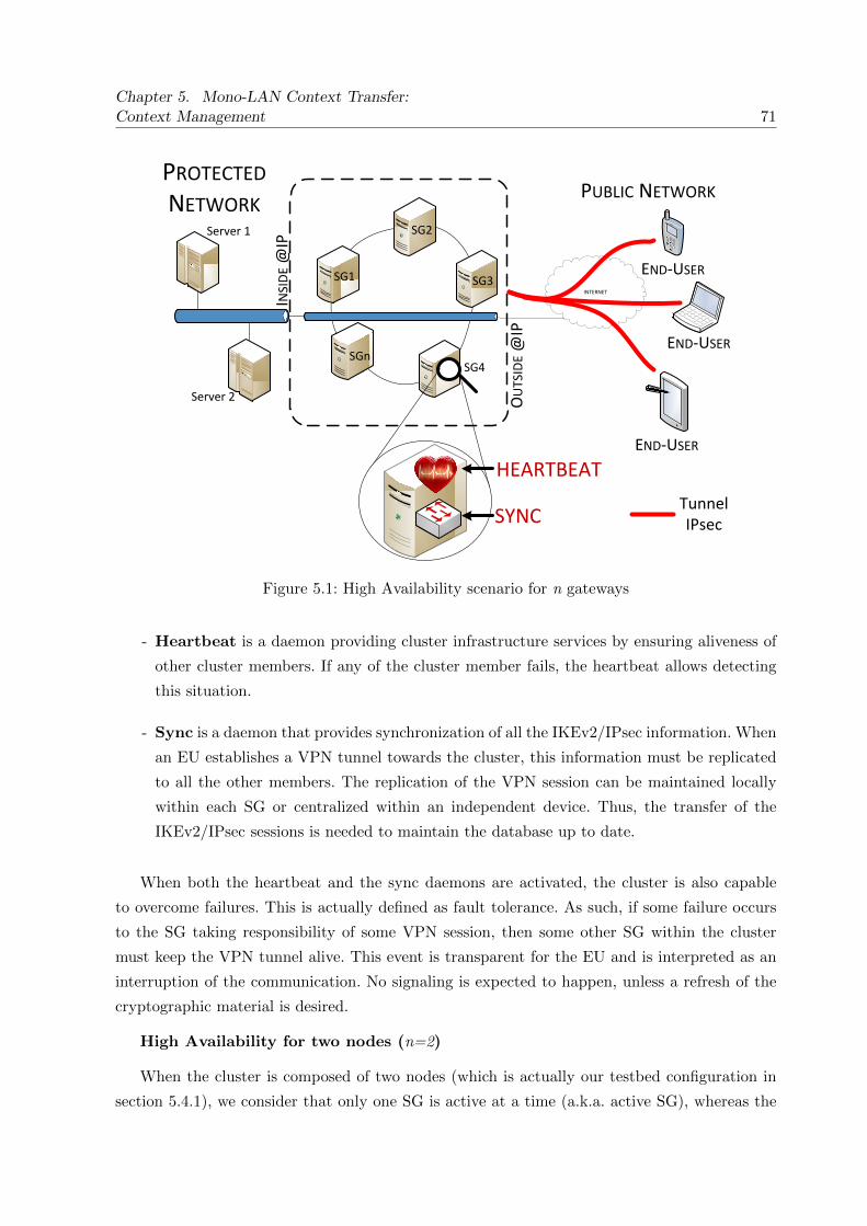
Chapter 5. Mono-LAN Context Transfer:Context Management 71
SG1
SG2
SGnSG4
END-USER
END-USER
PUBLIC NETWORKPROTECTED NETWORK
SYNC
SG3END-USER
INTERNET
Server 2
Server 1
Tunnel IPsec
HEARTBEAT
INSI
DE
@IP
OU
TSID
E @
IP
Figure 5.1: High Availability scenario for n gateways
- Heartbeat is a daemon providing cluster infrastructure services by ensuring aliveness of
other cluster members. If any of the cluster member fails, the heartbeat allows detecting
this situation.
- Sync is a daemon that provides synchronization of all the IKEv2/IPsec information. When
an EU establishes a VPN tunnel towards the cluster, this information must be replicated
to all the other members. The replication of the VPN session can be maintained locally
within each SG or centralized within an independent device. Thus, the transfer of the
IKEv2/IPsec sessions is needed to maintain the database up to date.
When both the heartbeat and the sync daemons are activated, the cluster is also capable
to overcome failures. This is actually defined as fault tolerance. As such, if some failure occurs
to the SG taking responsibility of some VPN session, then some other SG within the cluster
must keep the VPN tunnel alive. This event is transparent for the EU and is interpreted as an
interruption of the communication. No signaling is expected to happen, unless a refresh of the
cryptographic material is desired.
High Availability for two nodes (n=2)
When the cluster is composed of two nodes (which is actually our testbed configuration in
section 5.4.1), we consider that only one SG is active at a time (a.k.a. active SG), whereas the

72 5.2. Scenarios: HA and Context Management
Figure 5.2: High Availability scenario for n=2 nodes
other SG is considered as standby SG (which may become active whenever the first one fails).
The active cluster member synchronizes every VPN session with its neighbor. This ensures
perfect timing and synchronization of all the active VPN tunnels in the cluster.
As in section 5.2.1, we activate the heartbeat and a sync daemons which both ensure a
keep alive mechanism together with IKEv2/IPsec state synchronization (including IKEv2/IPsec
counters).
Figure 5.2 represents a cluster of n=2, where only one SG is active at a time. The SG1
(VPN Gateway 1) is considered as the initially active SG and is responsible for all incoming
requests. Suddenly, some failure occurs in SG1 and then the SG2 becomes the active SG, taking
responsibility of all the VPN connections. In this scenario, all the IKEv2/IPsec contexts that are
stored in SG1 are also replicated on SG2 through the sync daemon (introduced in section 5.2.1).
As such, when switching from SG1 to SG2, the VPN cluster offers fault tolerance and ensures
the high availability of the VPN service.
5.2.2 Context Management
The second scenario considered is called context management (see figure B.4). The context
management scenario includes an End-User that demands some service placed behind the cluster
of SGs. The EU establishes a VPN tunnel in order to access a service securely (i.e. streaming
video, mail server, web server, etc.). However, in some cases, the SG where a client is attached
can get overloaded. The risk to loose connectivity with the SG2 is high. Some other SG (i.e. SG3)
offers better performance to the EU than the initial SG2. It might be advantageous in terms
of QoS, reachability, latency, among other reasons, to transfer the IKEv2/IPsec context from
SG2 towards SG3. We intend to dynamically manage the VPN sessions between different SGs,
allowing transparent context management. As the IP address of the cluster remains the same in
Mono-LAN scenarios, no signaling is expected to happen among EUs and the SG. As shown in

Chapter 5. Mono-LAN Context Transfer:Context Management 73
SG3
END-USER
SGn
VPN Database
VPN Database
VPN Database
VPN Database
IPSEC TUNNELDATA FLOW
SG1 SG2
CONTEXT TRANSFER
Figure 5.3: Context Management scenario
figure B.4, the IKEv2/IPsec context is transferred from SG2 to SG3 and all layers above benefit
from this. Thus, no signaling is needed and this transfer is transparent for upper layers. This is
only interpreted as some interruption or network delays. This avoids re-authentication towards
the new SG, which in our example is SG3.
5.3 Position of our Work
Considering a Mono-LAN architecture, we positioned our work with some other protocols and
documents that address similar topics. First we introduce an IETF document (RFC3374),
which describes some reasons to perform a context transfer (regardless of the type of context
transfer: IPsec, TLS, IP, etc.). Then, another IETF document (RFC6311) presents some recent
investigations addressing the re-synchronization of IPsec counters for High Availability purposes.
Finally, we present VRRP, a protocol offering similar solutions to ClusterIP (discussed in
section 4.5), but it also defines a framework to set master/slave routers to provide fault tolerance
features.
- RFC3374 - Problem Description: Reasons for Performing Context Transfers
Between Nodes in an IP Access Network [40]: This Informational IETF document
expresses the needs for transferring a service-candidate context and illustrates the overview
of the reasons to perform a transfer of context between nodes in an IP Access Networks.
It is often the case that a peer connected to a router, establishes a context of a service

74 5.3. Position of our Work
that is provided by the access network. Usually, this service provides access to a subnet
just like it is the case of IKEv2/IPsec protocol. The set of parameters to establish the
connection between a peer and the router are the security associations. This information
can be transferred from one router to another in order to boost the re-establishment of
the connection when the IKEv2/IPsec Security Association is transferred between routers.
However, there are advantages and drawbacks. The main advantage is the possibility of a
fast service re-establishment (i.e. AAA, QoS, IKE Authentication, etc). However, one of the
drawbacks is the compatibility between different routers. On the other hand, they might
be situations where the access networks (or even the routers) would prefer to initialize a
new session from scratch. In our case, for an IPsec environment, the established security
associations between the node and the SG are supposed to be static. Nevertheless, new
challenges like mobility, context transfer, multihoming, among others, concern IPsec. This
causes some issues due to its static design. Properties like load sharing, load balancing,
context management and high availability, are some of the reasons to justify the transfer
of an IKEv2/IPsec context between SGs.
- RFC6311- Protocol Support for High Availability of IKEv2/IPsec [15]: as
discussed in section 4.4, one main obstacle to perform HA or context management under
IPsec environments are the counters associated with every security association established.
This standard defines an extension of IKEv2 in order to allow resynchronization of those
counters. There are actually two types of them: message ID and sequence numbers (see
section 4.4 for details). When transferring the IKEv2/IPsec context between different SGs,
we have taken into account the solution proposed by this standard: move the sequence
numbers forward, for example, by adding 10.000 to the sequence number value, avoiding
anti-replay protection delays. Actually, the IPsec standard does not forbid the fact to raise
at some point the value of the sequence numbers. For example, when transferring a VPN
session from one SG to another, it is almost sure that some packets treated by the new
SG will be stale. These packets will be considered by the End-User as a replay attack and
will be dropped. If these packets had higher sequence number, then they would have been
decrypted/authenticated by the End-User normally. As such, each time we perform an
IKEv2/IPsec context transfer, we rise the sequence numbers by a value of 10.000, avoiding
stale counters.
- RFC3768 - The Virtual Router Redundancy Protocol (VRRP) [41]: intends
to add fault tolerance of a single point of attachment in a network. VRRP creates a
group of SG under a same virtual IP. Thus, the whole set of machines are acting as a
single SG. Every interface that is configured with VRRP owns a virtual IP address that
is common to all routers being part of the redundant topology. In the case where two
or more SGs are configured with VRRP, the responsibility is determined by parameter

Chapter 5. Mono-LAN Context Transfer:Context Management 75
Figure 5.4: Original audio file transmitted on streaming during tests
called vrrp-priority. It defines which SG has the highest priority for getting responsibility
among the group. The goal is to simulate a default SG with a unique IP address so that
any End-User acceSSING through one of the SG does not know that there are many SGs
composing the cluster. The responsible SG acting as default SG is called master virtual
router, whereas all the other SGs are called backup virtual routers, which are ready to get
the role of master virtual router and to forward packets if the master virtual router ever
fails. Note that VRRP does not aim to perform load-balancing as it does not distribute
the load of VPNs among different routers, but it adds fault tolerance (redundancy) to
the network. In contrast, ClusterIP is able to spread the load among different SGs based
on the hash of some input information (i.e. source IP address, destination IP address,
port number, etc.). This permits VPN distribution among different SGs within a cluster,
even though synchronization of the IKEv2/IPsec context must take place independently in
order to ensure continuity of the VPN service. If we ever had to decide to use either VRRP
or ClusterIP, we would most likely prioritize ClusterIP because it allows some sort of load
sharing. However, the main drawback of ClusterIP is its limitation to be configured within
the same network segment, disturbing the deployment of geographically distant SGs.
5.4 Performance Tests
5.4.1 Testbed description and scenarios
All our measurements are performed over an active VPN session during an audio streaming
transmission with a duration of 8 seconds. Figure 5.4 illustrates the original audio file that is
transmitted during tests. The signal contains a sentence pronounced by a woman and man. It
is sampled at 48 kHz and contains up to 14 kHz signals.
We wish to measure the impact that HA and context management scenarios have on a
VPN session. We consider different bit rate transmissions when streaming at 8Kpbs, 48Kbps
and 96Kbps, evaluating the impact on the QoS (described in section 5.4.2.3). Additionally, we
measure the impact of using two different encryption methods: CBC and CTR (described in

76 5.4. Performance Tests
Architectures Protocol Encryptionalgorithms
Transmission bitrate
Frequency of interruptions[times/sec]
HighAvailability(HA)Contextmanagement(CxtM)
RTSPAES-CBC
8kbps f=0/8s(UDP) f=1/8s
48kbps f=2/8sHTTP
AES-CTRf=3/8s
(TCP) 96kbps f=4/8s
Table 5.1: Architectures and parameters addressed during tests
section 5.4.2.2). We also consider different transmission protocols: HTTP and RTSP, based on
TCP and UDP respectively (see section 5.4.2.1 for details). Finally, we vary the frequency of
HA and context management events. A switching frequency of f=1/8s means that only one event
takes place during the 8sec streaming, f=2/8s means two events,f=3/8s means three, and so on.
Table 5.1 summarizes the set of architectures and parameters for all our tests. The scenario
we are considering is: initially, an EU establishes a VPN towards the cluster (composed of two
nodes). This allows the EU to reach the streaming server in a secure manner. Then, the EU
receives an audio streaming with a duration of 8sec. Depending on the scenario, our performance
tests are conducted either with HA features enabled (heartbeat and sync daemons activated as
in section 5.2.1) or with context management features enabled (as in section 5.2.2). Once the
streaming has finished, the original source file is compared with the received audio file recorded
during streaming in order to measure the QoS by using the software POLQA (see 5.4.2.4).
- First testbed and scenario - HA: our first testbed, shown in figure 5.5, represents
the logic topology of the HA cluster. This testbed includes an audio streaming server, an
IPsec peer (EU) and two VPN SGs (SG1 and SG2). The sync daemon synchronizes every
IKEv2/IPsec context established on both SGs and the heartbeat daemon is responsible
for checking liveness of each SG every second. We focus on how to ensure fault tolerance
and high availability features to EUs. Thus, during the audio streaming transmission, we
simulate failures and vary the frequency of interruption 1/8s,2/8s,3/8s and 4/8s) events on
the cluster. This automatically activates the mechanisms to ensure continuity of service
of the VPN service and makes the standby SG becomes the active SG and vice-versa. For
experimental purposes, we have synchronized one VPN session.
- Second testbed and scenario - context management: the second testbed is shown
in figure 5.6. It represents the logic topology of the testbed and also includes an audio
streaming server, an IPsec peer (EU) and two VPN SGs (SG1 and SG2). We perform
manual switching of a VPN session by transferring the IKEv2/IPsec context from one SG1
to SG2 (and vice-versa) using different frequencies (1/8s,2/8s,3/8s and 4/8s). The objective
is to successfully manage an IKEv2/IPsec context between SGs at anytime during an

Chapter 5. Mono-LAN Context Transfer:Context Management 77
SG2SG1 HEARTBEAT
SYNC
END-USER
AUDIO STREAMING
SERVER
10.0.0.3
10.0.0.4
eth1
eth0 eth0
eth1
192.168.1.2
192.168.1.4
TRUSTED NETWORK
UNTRUSTED NETWORK
CLE
AR
ENC
RYP
TED
Figure 5.5: Testbed 1 - High Availability
audio streaming over an active VPN session, evaluating the impact over the IPsec layer
and upper layers, as well as to provide some performance measurements during the audio
transmission.
5.4.2 Protocols, parameters and audio streaming tools
This section describes in detail the different methods, protocols and bit rates used during our
performance tests. We compare the difference and introduce the impact that they may have
when securing with IPsec. The following list shows the different parameters, protocols and tools
used for the tests:
� Protocol for audio transmission: HTTP vs. HTTP
� Encryption algorithms: AES128-CBC vs. AES128-CTR
� Audio tools supporting several bit rates: 8kbps, 48Kbps or 96Kbps
� Software for measuring audio QoS: POLQA

78 5.4. Performance Tests
SG2SG1
10.0.0.3
10.0.0.4
eth1
eth0 eth0
eth1
192.168.1.2
192.168.1.4
TRUSTED NETWORK
UNTRUSTED NETWORK
CLE
AR
ENC
RYP
TED
SAD-SPD SAD-SPD
AUDIO STREAMING
SERVER
END-USER
CONTEXT MANAGEMENT
VPN SESSION’S PATH
Figure 5.6: Testbed 2 - Context Management
5.4.2.1 Protocols for audio streaming transmission: RTSP vs. HTTP
We have considered two protocols for the audio streaming transmission, RTSP and HTTP.
RTSP stands for Real Time Streaming Protocol, whereas HTTP stands for Hypertext Transfer
Protocol.
This section is intended to explain how the audio streaming data flow is built, based on
RTSP or HTTP, and protected with an IPsec environment. Figure 5.8 shows the packet format
when securing a RTSP audio streaming (over UDP) with IPsec (ESP) in tunnel mode (refer
to section 2.3.2 for details). On the other hand, figure 5.7 illustrates the packet format when
performing HTTP audio streaming (over TCP) secured with IPsec (ESP) in tunnel mode. The
RTSP and HTTP payload length varies depending on the audio source data itself. For example,
during silences in the audio streaming, the size of the packets may be shorter than during voice
transmission. However, this also depends on how the data flow is treated by the transport layer.
This is discussed in more details in section 5.5.
Regarding the IPsec layer, the ESP header has a 4-byte length Security Parameter Index
(to identify the corresponding security association) and a 4-byte length sequence number,
which is part of the anti-replay protection of IPsec, avoiding duplicated packets with the same
sequence number during ESP authentication. Although some encryption algorithms do not need
padding to cipher a plaintext (e.g. CounTeR), ESP does require padding to 32-bit word-align the

Chapter 5. Mono-LAN Context Transfer:Context Management 79
Figure 5.7: HTTP audio streaming protected with IPsec
Figure 5.8: RTSP audio streaming protected with IPsec
80 5.4. Performance Tests
authentication data, and thus may add 0-255 bytes of padding. The ESP Pad Length and Next
Header fields must be right aligned in order to ensure that the ESP Auth (a.k.a. ICV, Integrity
Check Value) is aligned on a 4-bytes boundary. The ESP Pad length is 1-byte length, as well
as the following ESP NH field (Next Header). ESP NH is used to identify the protocol of the
payload. Finally, in order to ensure integrity of the data flow, we use SHA-1 as integrity check
algorithm, and the ESP Authentication Data Field contains a variable-length field computed
over the ESP header, ESP IV, payload, and ESP trailer fields (Padding, Pad Length and Next
Header).
5.4.2.2 Encryption algorithms: AES128-CBC vs. AES128-CTR
In terms of encryption, we have tested two different encryption algorithms: AES128-CBC and
AES128-CTR. Both encryption algorithms use AES128 as block cipher. However, different modes
of operation are tested: Cipher-Block Chaining (CBC) and CounTeR (CTR).
1. CBC: the mode of operation CBC is illustrated in figure 5.9. For encryption, the whole
clear message is separated in blocks of 16 octets. Whenever the last block length is smaller
than 16 octets, some padding is added in order to complete the block. Then, the first
block of plaintext is XORed (represented with a circular plus symbol) with a Initialization
Vector (IV). Notice that an IV is a block of bits used with the purpose of randomizing
the encryption of some data (i.e. even if the same text is encrypted several times, the
result is different each time). Then, the result of the XOR function is encrypted using
AES algorithm and a key of 128bits. Finally, this ciphertext is used as IV for the next
block of data and the process is repeated. Hence, this mode of operation does not allow
parallelized encryption. Nevertheless, the decryption process allows parallelization. The
blocks of ciphertexts are directly decrypted by the AES decryption algorithm together with
its corresponding key. Only the first block of cipher text is subject to XOR processing with
an IV. The rest of data blocks are XORed with the precedent ciphertext block (allowing
parallelization of the decryption process).
2. CTR: the mode of operation CTR is shown in figure 5.10. This mode of operation allows
using the same cipher block for encryption and decryption, it means that the decryption
key scheduling do not need to be implemented, making it simpler than other mode of
operations. For encryption, the key and a counter block of data are used as input of the
block cipher. This generates a random keystream which is XORed with the clear text
in order to obtain the ciphertext. The encryption process can be parallelized as there
are no chaining operations, allowing independent cipher block inputs. For decryption, the
same counter and keys are inputs of the block cipher and the ciphertext is XORed with
this keystream, which results in the plaintext again. However, during decryption, if the

Chapter 5. Mono-LAN Context Transfer:Context Management 81
Figure 5.9: AES128-CBC encryption
keystream is longer than the clear text or ciphertext, the additional keystream bits are
discarded. That is why, AES-CTR does not require padding completion to a multiple of
the block size (see [42] and [43] for details).
5.4.2.3 Audio tools supporting several bit rates: 8kbps, 48Kbps or 96Kbps
We used two implementations in order to transmit and record the audio streaming from the
server towards the EU during our tests: VLC and Arecord.
1. VLC stands for VideoLAN Client and server. It is an open source multimedia and
streaming player. We have used this software in order to perform audio streaming in a
client-server fashion. It supports various streaming protocols (refer to [44] for details).
Depending on the test, parameters on the command line are modified in order to change
the bit rate as well as the transmission protocol. We have tested three different bit rates:
8Kbps, 48Kbps and 96Kbps, as well as two different protocols: HTTP and RTSP (as
explained in section 5.4.2.1). VLC allows to output any stream to a network or a file.
Additionally, it allows processing the original streamed file in order to apply transcoding,
filters, among other signal treatments. Appendix ?? shows a list of commands to perform
audio streaming using different scenarios (i.e. protocols and bit rates). Finally, VLC also
includes different modules that have different capabilities. The modules used for our tests
are listed below:

82 5.4. Performance Tests
Figure 5.10: AES128-CTR encryption
(a) Standard: allows sending the stream to the network or saving it into a file. It has
an option called ’access’ which specifies the protocol of transmission (e.g. RTSP or
HTTP).
(b) Transcode: is used to decode and re-encode the streamed file using different bit rates
(e.g. 8Kbps, 48Kbps and 96Kbps).
2. Arecord is a native Linux command for audio recording (see [45]). It supports a large set
of soundcards and devices. The following command line captures the audio that is received
during the streaming:
arecord -f cd -d $vlc timeout duration /tmp/sound card record.wav
The parameters of the command are explained below:
-f, –format=FORMAT : format of the sample recorded. There exists a set of formats,
however, we used a format shortcut ”-f cd”, which represents a 16 bit little endian,
44.1KHz and stereo capture. This is the equivalent of a CD-quality wave file.
-d , –duration=N : interrupt recording after N seconds. Setting it to zero, means
infinity. We set this value to a variable called $vlc timeout duration.
File path : where the audio files is saved. In our case, /tmp/ directory. Then, at the end
of the test, the captured audio file is transmitted to a server with the rest of test logs.

Chapter 5. Mono-LAN Context Transfer:Context Management 83
5.4.2.4 Software for measuring audio QoS: POLQA
In terms of quality of service measurements (QoS), we use Perceptual Objective Listening Quality
Assessment, POLQA (see [17]). It is a relatively recent standard (2006-2011) for voice quality
testing technology which is available under license. Orange, as a leading mobile operator in
France, gets some licenses for using this software. Testing and measuring the impact of our
developments over the QoS for some audio streaming, is a manner to evaluate the performance
of our results.
5.5 Performance results
The results are represented in graphs with box-and-whiskers style (a.k.a. quartiles), as in
section 4.7.1 (refer to section 3.4.3 for more details). Section 5.5.1 includes the results concerning
the HA testbed considering different parameters (bit rates, frequency of interruption, etc.)
whereas section 5.5.2 shows the results concerning the context management testbed. For each
testbed, we analyze the network performances of our solution and then we concentrate on the
QoS performances. We represented graphically all the results considering the parameters showed
in table 5.1, and for each combination of parameters 25 measures were done in order to polt
statistical results as quartiles.
5.5.1 Results for High Availability
This section exposes the results obtained during the performance tests concerning our High
Availability solution. Section 5.5.1.1 shows the network performace and section 5.5.1.2 shows
the impacts on QoS for each considered parameter.
5.5.1.1 Network performances:
Our first result shows how a VPN session is impacted while the HA scenario takes place.
Figure 5.11 and 5.12 illustrate the switching time for all different scenarios and parameters
presented in section 5.4.2 during an audio streaming of 8sec. The term switching time is
considered as the network time that a VPN session is interrupted while being transferred from
SG1 to SG2 (or vice-versa). During a HA event (e.g. from SG1 to SG2), we calculate the switching
time by subtracting the time when the first packet arrives from SG2 by the time when the last
packet comes from SG1. This is done through the analysis of network captures during tests.
Figure 5.11 represents the case where the switching frequency (a.k.a. frequency of
interruption) is f=1/8s. It illustrates the time to switch from SG1 to SG2 according to the
bit rate used: 8Kbps, 48Kbps or 96Kbps. The left side of the graph represents HTTP and

84 5.5. Performance results
0 0.5
1 1.5
2 2.5
3 3.5
4 4.5
5 5.5
6 6.5
7 7.5
8 8.5
9
8Kbps
48Kbps
96Kbps
8Kbps
48Kbps
96Kbps
Tot
al in
terr
uptio
n tim
e (s
)
Bit Rate (Kbps)
HTTP RTSP
CBC CTR CBC CTR CBC CTR CBC CTR CBC CTR CBC CTR
Figure 5.11: Total switching time for one interruption (1/8s). High Availability - Audio sourcefile duration: 8 seconds
the right side corresponds to RTSP. The HTTP-CBC medians remain around 2sec, but the
quartiles are distant. This proves that HTTP is considerably impacted under an HA scenario. For
HTTP-CTR, whose quartile are also spaced, the medians starts from 2.5sec (for 48Kbps) until
4.2sec (for 8kbps), being HTTP-CTR-8Kbps the worst median performance and less stable result
of all cases for a switching frequency f=1/8s. On the other hand, in most scenarios, CBC had a
better performance than CTR (unless for HTTP-48kbps only). Considering RTSP, the switching
time is notably stable around 1.5sec, and the quartiles are narrower, evidencing stability of the
measure. This means that regardless of the encryption algorithm and application/transport
protocol used, this scenarios are fairly stable. Notice that we do not pretend to compare
HTTP against RTSP as application protocols. The objective is to explain the difference of
using whether HTTP or RTSP and to measure how our developments of HA impacts them in
different circumstances. Actually, we decided to use HTTP and RTSP, because HTTP relies
on TCP whereas RTSP relies on UDP protocol, allowing to study the impact over connection
oriented and non-connection oriented protocols. However, figure 5.11 illustrates that is better to
implement RTSP than HTTP while streaming under a HA environment.
Figure 5.12 illustrates the switching time caused by different switching frequencies from
1/8s to 4/8s (refer to 5.4.1 for details). In order to recreate a more realistic environment, the

Chapter 5. Mono-LAN Context Transfer:Context Management 85
0 0.5
1 1.5
2 2.5
3 3.5
4 4.5
5 5.5
6 6.5
7 7.5
8 8.5
9 9.5 10
10.5 11
11.5 12
12.5 13
13.5 14
14.5 15
15.5 16
16.5 17
17.5 18
18.5 19
19.5 20
20.5 21
21.5 22
22.5 23
1/8s2/8s
3/8s4/8s
1/8s2/8s
3/8s4/8s
1/8s2/8s
3/8s4/8s
Tot
al s
witc
hing
tim
e (s
)
Switching frequency
HTTP
8Kbps 48Kbps 96KbpsC
BC
CT
R
CB
C
CT
R
CB
C
CT
R
CB
C
CT
R
CB
C
CT
R
CB
C
CT
R
CB
C
CT
R
CB
C
CT
R
CB
C
CT
R
CB
C
CT
R
CB
C
CT
R
CB
C
CT
R
(a) Protocol: HTTP
0 0.5
1 1.5
2 2.5
3 3.5
4 4.5
5 5.5
6 6.5
7 7.5
8 8.5
9 9.5 10
10.5 11
11.5 12
12.5 13
13.5 14
14.5 15
15.5 16
16.5 17
17.5 18
1/8s2/8s
3/8s4/8s
1/8s2/8s
3/8s4/8s
1/8s2/8s
3/8s4/8s
Tot
al s
witc
hing
tim
e (s
)
Switching frequency
RTSP
8Kbps 48Kbps 96Kbps
CB
C
CT
R
CB
C
CT
R
CB
C
CT
R
CB
C
CT
R
CB
C
CT
R
CB
C
CT
R
CB
C
CT
R
CB
C
CT
R
CB
C
CT
R
CB
C
CT
R
CB
C
CT
R
CB
C
CT
R
(b) Protocol: RTSP
Figure 5.12: Switching time for several interruption frequencies (1/8s,2/8s,3/8s and 4/8s). HighAvailability - Audio source file 8sec

86 5.5. Performance results
interruptions are randomly generated on time so that failover events never take place at the same
time. Figure 5.12a illustrates the total switching time when using HTTP whereas figure 5.12b
represents RTSP.
Both figures 5.12a and 5.12b show an unstable response facing the different switching
frequencies. Even though the quartiles are spaced, the total switching time increases linearly
when streaming over HTTP. In the case of RTSP, the total switching time remains stable
during frequency 1/8s, but quartiles become more spread when the frequency of interruption
increases. We noticed through network captures that the HTTP audio streaming packet sizes are
considerably bigger than those packets of an RTSP audio streaming. This explains why HTTP
audio streaming gets more impacted in terms of network performance, usually taking more time
to overcome a failure event. As HTTP is based on TCP, this connection-oriented protocol ensures
reliability, ordering, and error-checking of delivered stream of octets. This situations leads to
a considerable overhead and higher impact during interruptions, as more information must to
be retransmitted. Thus, loosing some information when using HTTP streaming might represent
more troubles than streaming with RTSP. Due to the connection-less oriented behavior of RTSP
(based on UDP), those packets that are lost are not sent again, which represents lower overhead.
5.5.1.2 Quality of Service:
Figures 5.13 and 5.14 show all the results in terms of QoS. POLQA’s scores from zero (low
quality audio) to five (high quality audio).
Figures 5.13a and 5.13b represent the results of the QoS for different switching frequencies,
which are represented as 1/8s,2/8s,3/8s and 4/8s. We also added quartiles for frequency zero (0/8s),
which represents the reference QoS for each case. This allows comparing the QoS deterioration as
long as we increase the switching frequency. We observe that as soon as the switching frequency
increments, both 48Kbps and 96Kbps (HTTP and RTSP) downgrade the QoS. However, when
using 8Kbps bit rate, the QoS smoothly improves as the switching frequencies increase.
A bit rate of 8Kbps is considered as a very bad quality by POLQA, and the note always
remain below of 1.25/5. During interruptions, POLQA gives a slightly better QoS than the
reference QoS, meaning that the interruptions are actually similar to an audio with compression
of 8Kbps. On the other hand, 48Kbps and 96Kbps decrease in terms of QoS regardless of the
encryption algorithm while the switching frequency increases.
Finally, figure 5.14a illustrates the loss of QoS when the switching frequency is 1/8s. This figure
is also partially represented in figure 5.13, but this time we show the results according to the bit
rate (instead of switching frequencies). Also, we added an additional quartile called Reference
QoS. In fact, the Reference QoS consist of measuring the quality of an audio streaming while
no interruption takes place. This is how we can actually measure the impact of the interruption

Chapter 5. Mono-LAN Context Transfer:Context Management 87
0 0.25 0.5
0.75 1
1.25 1.5
1.75 2
2.25 2.5
2.75 3
3.25 3.5
3.75 4
4.25 4.5
4.75 5
0/8s1/8s
2/8s3/8s
4/8s0/8s
1/8s2/8s
3/8s4/8s
0/8s1/8s
2/8s3/8s
4/8s
POL
QA
- Q
oS
Switching frequency
HTTP
8Kbps 48Kbps 96KbpsR
efer
ence
CB
CR
efer
ence
CT
R
CB
CC
TR
CB
CC
TR
CB
CC
TR
CB
CC
TR
Ref
eren
ce C
BC
Ref
eren
ce C
TR
CB
CC
TR
CB
CC
TR
CB
CC
TR
CB
CC
TR
Ref
eren
ce C
BC
Ref
eren
ce C
TR
CB
CC
TR
CB
CC
TR
CB
CC
TR
CB
CC
TR
(a) Protocol: HTTP. Architecture: High Availability
0 0.25 0.5
0.75 1
1.25 1.5
1.75 2
2.25 2.5
2.75 3
3.25 3.5
3.75 4
4.25 4.5
4.75 5
0/8s1/8s
2/8s3/8s
4/8s0/8s
1/8s2/8s
3/8s4/8s
0/8s1/8s
2/8s3/8s
4/8s
POL
QA
- Q
oS
Switching frequency
RTSP
8Kbps 48Kbps 96Kbps
Ref
eren
ce C
BC
Ref
eren
ce C
TR
CB
CC
TR
CB
CC
TR
CB
CC
TR
CB
CC
TR
Ref
eren
ce C
BC
Ref
eren
ce C
TR
CB
CC
TR
CB
CC
TR
CB
CC
TR
CB
CC
TR
Ref
eren
ce C
BC
Ref
eren
ce C
TR
CB
CC
TR
CB
CC
TR
CB
CC
TR
CB
CC
TR
(b) Protocol: RTSP. Architecture: High Availability
Figure 5.13: QoS for several interruption frequencies (1/8s,2/8s,3/8s and 4/8s). High Availability -Audio source file duration: 8 seconds

88 5.5. Performance results
0 0.25
0.5 0.75
1 1.25
1.5 1.75
2 2.25
2.5 2.75
3 3.25
3.5 3.75
4 4.25
4.5 4.75
5
8Kbps
48Kbps
96Kbps
8Kbps
48Kbps
96Kbps
POL
QA
- Q
oS
Bit Rate (Kbps)
HTTP RTSPR
efer
ence
CB
C
Ref
eren
ce C
TR
Ref
eren
ce C
BC
Ref
eren
ce C
TR
Ref
eren
ce C
BC
Ref
eren
ce C
TR
Ref
eren
ce C
BC
Ref
eren
ce C
TR
Ref
eren
ce C
BC
Ref
eren
ce C
TR
Ref
eren
ce C
BC
Ref
eren
ce C
TR
CB
C
CT
R
CB
C
CT
R
CB
C
CT
R
CB
C
CT
R
CB
C
CT
R
CB
C
CT
R
Figure 5.14: QoS measurements for one interruption frequency (1/8s). High Availability - Audiosource file: 8 seconds
by comparing it with different switching frequencies (1/8s,2/8s,3/8s and 4/8s).
By comparing the switching frequency f=1/8s with the reference QoS, we obtained
the following main results: the QoS for HTTP-48Kbps is degraded by around 50%,
HTTP-96Kbps-CBC by 35% and HTTP-96Kbps-CTR by 58%. The 8Kbps results are
particularly different. The POLQA’s algorithm gives a very bad note to any transmission made
with 8Kbps. Audio streaming at this rate does not accomplish a good level of quality, thus
obtaining an average note of 1.23/5. Even for interruption where switching frequency is 1/8s,
POLQA gives a better note as the reference QoS. This means that interruptions are better
noted than the audio transmission itself due to its bad quality. For further details in how POLQA
algorithms objectively evaluates audio quality, refer to [46]. Table B.2 summarizes the results of
QoS as long as the switching frequencies increase for all the cases.
5.5.2 Results for context management
This sections exposes the results obtained during the performance tests for our context
management scenario. Section 5.5.2.1 shows the network performance and section 5.5.2.2 presents
the impacts on QoS for each considered parameter.

Chapter 5. Mono-LAN Context Transfer:Context Management 89
High Availability Reference QoS (0/8s) 1/8s 2/8s 3/8s 4/8s
HTTP-8Kbps-CBC 100% +3% +6% +17% +17%HTTP-8Kbps-CTR 100% 0% +19% +19% +19%HTTP-48Kbps-CBC 100% -50.5% -68% -70% -69%HTTP-48Kbps-CTR 100% -52% -62% -69% -69%HTTP-96Kbps-CBC 100% -27% -67% -71% -69%HTTP-96Kbps-CTR 100% -60% -63% -71% -72%
RTSP-8Kbps-CBC 100% +14% +31% +38% +34%RTSP-8Kbps-CTR 100% +9% +39% +39% +30%RTSP-48Kbps-CBC 100% -40% -52% -49% -51%RTSP-48Kbps-CTR 100% -60% -63% -62% -61%RTSP-96Kbps-CBC 100% -57% -60% -59% -60%RTSP-96Kbps-CTR 100% -56% -58% -57% -58%
Table 5.2: Impact of the frequency of high availability events over QoS (considering the medians)
5.5.2.1 Network performances:
Figures 5.15 and 5.16 represent the results of an IKEv2/IPsec context transfer under the context
management testbed, considering all the parameters and scenarios described in section 5.4.2.
Notice that measurements take place during a streaming transmission of an audio source file
with a duration of 8sec.
Figure 5.15 illustrates the total switching time for different switching frequency cases. As
for the HA testbed, the total switching time is calculated as the accumulated time when
switching from SG1 to SG2 and vice-versa: 1/8s,2/8s,3/8s and 4/8s. Figure 5.15a and 5.15b show
a linear tendency upwards. Quartiles for the HTTP scenario are more spaced than those
of RTSP, showing that RTSP is more stable in terms of network performance than HTTP
during interruptions. Regardless of which encryption algorithm is implemented, CBC and CTR
algorithms show similar performances. Only HTTP-48Kbps indicates a little advantage of CBC
compared to CTR, but in general terms, both algorithm perform similarly. As our testbed
includes a 2-core CPU’s, this is the main reason why it does not make a huge influence in
terms of total switching time. For RTSP protocol (fig 5.15b), CTR showed a 3% to 5% better
performance than CBC.
Figure 5.16 shows the switching time in function of different bit rates, considering a switching
frequency of 1/8s. For both protocols, the median remains very stable. We notice that RTSP
performs better than HTTP. In fact, HTTP takes in average 25% more time to switch from SG1
to SG2 than RTSP. Although the quartiles are narrow, sometimes HTTP takes 3sec to 3.5sec
to perform a context management event (i.e. HTTP-CBC-8Kbps and HTTP-CTR-96Kbps).
Concerning the cryptographic algorithms, CBC and CTR obtained very similar results. We
observe that regardless of the bit rate used, this has no impact over the type of encryption.
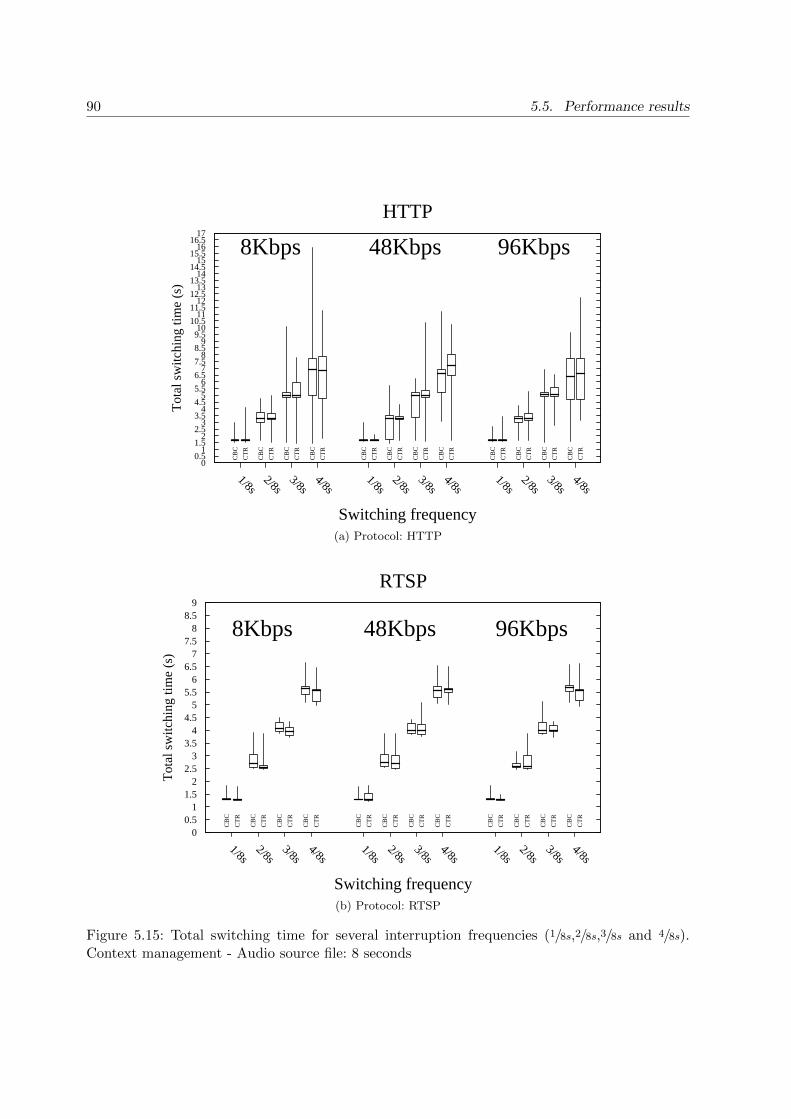
90 5.5. Performance results
0 0.5
1 1.5
2 2.5
3 3.5
4 4.5
5 5.5
6 6.5
7 7.5
8 8.5
9 9.5 10
10.5 11
11.5 12
12.5 13
13.5 14
14.5 15
15.5 16
16.5 17
1/8s2/8s
3/8s4/8s
1/8s2/8s
3/8s4/8s
1/8s2/8s
3/8s4/8s
Tot
al s
witc
hing
tim
e (s
)
Switching frequency
HTTP
8Kbps 48Kbps 96KbpsC
BC
CT
R
CB
C
CT
R
CB
C
CT
R
CB
C
CT
R
CB
C
CT
R
CB
C
CT
R
CB
C
CT
R
CB
C
CT
R
CB
C
CT
R
CB
C
CT
R
CB
C
CT
R
CB
C
CT
R
(a) Protocol: HTTP
0 0.5
1 1.5
2 2.5
3 3.5
4 4.5
5 5.5
6 6.5
7 7.5
8 8.5
9
1/8s2/8s
3/8s4/8s
1/8s2/8s
3/8s4/8s
1/8s2/8s
3/8s4/8s
Tot
al s
witc
hing
tim
e (s
)
Switching frequency
RTSP
8Kbps 48Kbps 96Kbps
CB
C
CT
R
CB
C
CT
R
CB
C
CT
R
CB
C
CT
R
CB
C
CT
R
CB
C
CT
R
CB
C
CT
R
CB
C
CT
R
CB
C
CT
R
CB
C
CT
R
CB
C
CT
R
CB
C
CT
R
(b) Protocol: RTSP
Figure 5.15: Total switching time for several interruption frequencies (1/8s,2/8s,3/8s and 4/8s).Context management - Audio source file: 8 seconds

Chapter 5. Mono-LAN Context Transfer:Context Management 91
1
1.25
1.5
1.75
2
2.25
2.5
2.75
3
3.25
3.5
8Kbps
48Kbps
96Kbps
8Kbps
48Kbps
96Kbps
Tot
al in
terr
uptio
n tim
e (s
)
Bit Rate (Kbps)
HTTP RTSP
CBC CTR CBC CTR CBC CTR
CBC CTR CBC CTR CBC CTR
Figure 5.16: Switching time for one interruption (1/8s) - Context management - Audio sourcefile: 8 seconds

92 5.5. Performance results
5.5.2.2 Quality of Service:
Figures 5.17 and 5.18 illustrate results in terms of QoS. We consider the same scenarios and
parameters as for the network performance results, so we can compare them.
Figure 5.17 shows the QoS for several switching frequencies (1/8s,2/8s,3/8s and 4/8s). As for the
HA testbed (refer to 5.5.1.2), we also added quartiles for frequency zero (0/8s). This represents
the reference QoS for each considered scenario. This allows comparing the QoS deterioration as
long as we increase the switching frequency.
Figure 5.17a represents the variation of the QoS while streaming under HTTP. 8Kbps obtains
poor marks as in HA testbed ( 1.25/5). In terms of QoS, 8Kbps is strongly discouraged to use.
Actually, by performing audio streaming at 8Kbps we might gain in terms of bandwidth but
loose in terms of quality. On the other hand, HTTP-48Kbps and HTTP-96Kbps both maintain
acceptable good notes as long as the switching frequency increases. Even though the QoS is
logically downgraded while increasing the amount of interruptions, HTTP maintains a fair QoS.
Note that HTTP uses TCP as transport protocol, which ensures lost packets to be resent,
maintaining a good behavior in terms of QoS. However this may represent high bandwidth
consumption as well as longer delays when listening to the audio streaming. For example, in
terms of network performance, HTTP shows higher interruption levels when increasing the
switching frequencies than RTSP (see fig 5.15). Figure 5.17b represents the QoS for several
switching frequencies with RTSP, showing that it is clearly more impacted in terms of QoS than
HTTP. Although RTSP showed good results in terms of network performance by switching from
SG1 to SG2 in 1.3sec, this is not the case in terms of QoS. In fact, as RTSP is based on UDP,
connectionless-oriented protocols do not resend lost packets, introducing higher impacts on the
QoS of the streaming. When using RTSP, the impact over the QoS for 1/8s,2/8s,3/8s and 4/8s
switching frequencies are (in average): 36,5%, 50%, 55,75% and 57,5% correspondingly.
Finally, figure 5.18 shows the QoS evaluation for different bit rates with a switching frequency
f=1/8s. We observe that RTSP is more impacted than HTTP. HTTP’s QoS decreases by 18%
and 28% (CBC-48Kbps and CBC 96Kbps) while RTSP’s QoS decreases by 31% and 53%
(CBC-48Kbps and CBC 96Kbps). However, in some cases RTSP has less impact on the QoS than
HTTP in percentage (i.e. -41% using HTTP-48Kbps-CTR and -35% using RTSP-48Kbps-CTR),
but in fact, the reference QoS is also staled since the beginning (i.e. 4.5/5 for HTTP-48Kbps-CTR
against 3.25/5 for RTSP-48Kbps-CTR). This means that, in some cases, the HTTP streaming
might be a little bit more impacted than RTSP streaming, but the QoS remains the best when
using HTTP. Table B.3 summarizes the evaluation of the QoS as long as the switching frequencies
increase on a context management scenario.

Chapter 5. Mono-LAN Context Transfer:Context Management 93
0 0.25 0.5
0.75 1
1.25 1.5
1.75 2
2.25 2.5
2.75 3
3.25 3.5
3.75 4
4.25 4.5
4.75 5
0/8s1/8s
2/8s3/8s
4/8s0/8s
1/8s2/8s
3/8s4/8s
0/8s1/8s
2/8s3/8s
4/8s
POL
QA
- Q
oS
Switching frequency
HTTP
8Kbps 48Kbps 96KbpsR
efer
ence
CB
CR
efer
ence
CT
R
CB
CC
TR
CB
CC
TR
CB
CC
TR
CB
CC
TR
Ref
eren
ce C
BC
Ref
eren
ce C
TR
CB
CC
TR
CB
CC
TR
CB
CC
TR
CB
CC
TR
Ref
eren
ce C
BC
Ref
eren
ce C
TR
CB
CC
TR
CB
CC
TR
CB
CC
TR
CB
CC
TR
(a) Protocol: HTTP
0 0.25 0.5
0.75 1
1.25 1.5
1.75 2
2.25 2.5
2.75 3
3.25 3.5
3.75 4
4.25 4.5
4.75 5
0/8s1/8s
2/8s3/8s
4/8s0/8s
1/8s2/8s
3/8s4/8s
0/8s1/8s
2/8s3/8s
4/8s
POL
QA
- Q
oS
Switching frequency
RTSP
8Kbps 48Kbps 96Kbps
Ref
eren
ce C
BC
Ref
eren
ce C
TR
CB
CC
TR
CB
CC
TR
CB
CC
TR
CB
CC
TR
Ref
eren
ce C
BC
Ref
eren
ce C
TR
CB
CC
TR
CB
CC
TR
CB
CC
TR
CB
CC
TR
Ref
eren
ce C
BC
Ref
eren
ce C
TR
CB
CC
TR
CB
CC
TR
CB
CC
TR
CB
CC
TR
(b) Protocol: RTSP
Figure 5.17: QoS for several interruption frequencies (1/8s,2/8s,3/8s and 4/8s) - Contextmanagement - Audio source file: 8 seconds

94 5.5. Performance results
0 0.25
0.5 0.75
1 1.25
1.5 1.75
2 2.25
2.5 2.75
3 3.25
3.5 3.75
4 4.25
4.5 4.75
5
8Kbps
48Kbps
96Kbps
8Kbps
48Kbps
96Kbps
POL
QA
- Q
oS
Bit Rate (Kbps)
HTTP RTSP
Ref
eren
ce C
BC
Ref
eren
ce C
TR
Ref
eren
ce C
BC
Ref
eren
ce C
TR
Ref
eren
ce C
BC
Ref
eren
ce C
TR
Ref
eren
ce C
BC
Ref
eren
ce C
TR
Ref
eren
ce C
BC
Ref
eren
ce C
TR
Ref
eren
ce C
BC
Ref
eren
ce C
TR
CB
C
CT
R
CB
C
CT
R
CB
C
CT
R
CB
C
CT
R
CB
C
CT
R
CB
C
CT
R
Figure 5.18: QoS measurements for one interruption frequency (1/8s). Context Management -Audio source file: 8 seconds
Context Management Reference QoS (0/8s) 1/8s 2/8s 3/8s 4/8s
HTTP-8Kbps-CBC 100% 0% +1% 0% +1%HTTP-8Kbps-CTR 100% 0% 0% +5% +1%HTTP-48Kbps-CBC 100% -18% -20% -40% -28%HTTP-48Kbps-CTR 100% -41% -31% -39% -33%HTTP-96Kbps-CBC 100% -28% -16% -40% -48%HTTP-96Kbps-CTR 100% -33% -20% -53% -50%
RTSP-8Kbps-CBC 100% 0% +16% +21% +28%RTSP-8Kbps-CTR 100% +3% +15% +23% +28%RTSP-48Kbps-CBC 100% -31% -41% -50% -52%RTSP-48Kbps-CTR 100% -35% -57% -58% -61%RTSP-96Kbps-CBC 100% -53% -61% -66% -68%RTSP-96Kbps-CTR 100% -27% -43% -49% -49%
Table 5.3: Impact of the frequency of context management events over QoS (considering themedians)

Chapter 5. Mono-LAN Context Transfer:Context Management 95
5.6 Conclusions
Throughout this chapter we described the IKEv2/IPsec context transfer under a Mono-LAN
environment, where a cluster offering a VPN service is configured with a common IP address.
Contrary to chapter 4, this time our scenarios included the IKEv2/IPsec context transfer
between physically different SGs. We defined two new components: the heartbeat and the sync.
These components allows to synchronize every tunnel that is negotiated with any of the cluster
members, and the heartbeat regularly checks liveness of the nodes.
By introducing the High Availability architecture, we added the capability to successfully
overcome a failover event thanks to the constant replication of the IPsec and IKEv2 data. We
found out that an ISPs may be interested in deploying this architecture to ensure reliability of
the VPN service. On the other hand, by increasing the availability of the system, the End-User
experience and the QoS is improved when avoiding re-authentication when moving from one
SG to another. Also, the IKEv2/IPsec context management under a Mono-LAN environment
represents advantages for the VPN service. Indeed, an ISP wanting to balance the load among
different cluster members might use this feature to dynamically move an IPsec session from one
SG to other. This improves the performance of the VPN service and avoids overloaded gateways
within the cluster.
We tested two different scenarios: High Availability and Context Management. We also
consider several parameters throughout the tests: encryption methods, bit rate transmissions
as well as connection and non-connection oriented transport protocols. We found out that
the context management scenario performed better than HA. Actually, even if both scenarios
contemplate the transfer of an IKEv2/IPsec context, they perform differently and might be
implemented in different circumstances. The heartbeat component of the HA scenario adds
automatism during failover occurrences, however the transfer of the IKEv2/IPsec context only
happens once the heartbeat gives the order to do so. Instead, under a Context Management
scenario, an ISP is able to move an IPsec session whenever needed, and thus improving the
performance and End-User experience. This is the main reason why the context management
scenario performed better than HA.
Our results are presented in terms of network behavior and QoS. During the HA tests,
we noticed that the network behavior of non-connection oriented protocols (i.e. UDP) are less
impacted by a failover event than a connection oriented protocol (i.e. TCP). In fact, due to
the nature of TCP which mandates to acknowledge transmitted data, this generates additional
delays to recover from failover events. However, from a QoS point of view, TCP obtained better
results than UDP. Indeed, with UDP, those packets that are lost during failover events are
not recovered, thus degrading the QoS. Considering the context management, we noticed that
connection oriented protocols are less impacted compared to the scenario where HA features

96 5.6. Conclusions
are enabled. This is mainly due to the time that the heartbeat takes to perform its task.
Actually, during a context management, there is no heartbeat involved during the transfer of
the IKEv2/IPsec context, and thus, the SG taking responsibility of a connection does not need
to wait the liveness check to install the new IPsec session. When comparing HTTP (TCP) with
RTSP (UDP), we noticed that RTSP has a better network behavior than HTTP. However, in
terms of QoS, HTTP obtains (once again) better results than RTSP.
We also measure the Mean Opinion Score (MOS), a measure of voice quality, with POLQA.
From the three different bit rates used, 92kbps consumes more capacity, but delivers an average
MOS of 4.75; 48kbps delivers a MOS slightly better than 4.3 and 8kbps delivers a MOS of 1.25.
Thus, an enterprise must decide whether MOS values deliver acceptable quality or whether they
would prefer to trade some bandwidth for higher quality.
Future work includes interaction of IPsec facing a context transfer between SGs with different
IP addresses. Even though we improved the VPN service by creating the cluster of nodes with a
single IP address, an ISP may also be interested in moving an IPsec session between distant SGs
with different IP addresses. We believe that this may be advantageous to ensure the continuity
of a VPN service for a mobile user that is probably changing its attachment point. This is
explained in details in chapter 6.

Part III
IPsec/IKEv2 Context Transfer forMulti-LAN architectures
97


Chapter 6
Multi-LAN IKEv2/IPsec ContextTransfer
This chapter introduces the IKEv2/IPsec context transfer considering SGs with different IP
addresses. This is what we call a Multi-LAN context transfer. Actually when a SG transfers
an IKEv2/IPsec context to another SG, all the security parameters and cryptographic material
are also transfered as fast as possible in order to avoid incoherent or unsynchronized states
(especially IPsec counters). Throughout this chapter, we introduce a mechanism based on
MOBIKE extension of IKEv2 (discussed in section 2.6) allowing to change the attachment
point of a peer during an active IPsec session. This includes the theoretical process to achieve
such mechanism as well as we provide some developments recommendations. The practical tests
and developments for this scenario are left as future work.
The chapter is organized as follows: section 6.1 describes the motivation of performing
Multi-LAN context transfers, then, section 6.2 positions our work compared to related topics
concerning the transfer of an IPsec context. Following section 6.2.3 focuses in explaining
MOBIKE extension and how it can be implemented to perform IKEv2/IPsec context transfers
(subsection 6.4). Finally we present our conclusions in section 6.5.
6.1 Motivations
An IKEv2/IPsec context transfer should be performed smoothly with respect to End-Users.
Our goal is to avoid the number of exchanges between the access network devices (SGs) and the
End-User during a context transfer. However, when the IP address associated to an IPsec VPN
tunnel changes, it is mandatory to update the corresponding IPsec and IKEv2 databases on both
extremities. This introduces some delays that might impact the EU experience during an active
IKEv2/IPsec session. We propose a solution by performing a GET action from the SG sending
99

100 6.2. Position of our Work
the context, and then performing a PUT action at the SG receiving the IKEv2/IPsec context.
However, in contrast to precedent chapters, an additional INFORMATIONAL IKEv2 message
must be exchanged between the EU and the SG in order to inform that the IP address changed.
This impacts the EU experience as it is involved during the transfer between SGs. Nevertheless,
MOBIKE is an ideal extension of IKEv2 allowing to perform our Multi-LAN context transfer,
as it avoids re-authentication from scratch, reducing delays in the establishment of a new tunnel
towards a new IP address.
Even though the mobility feature of MOBIKE was initially designed as to be applied from
the client side (which is supposed to be a mobile node), our solution can use this exchange at the
SG’s side, and update the IP address where a peer is attached to. However, this would introduce
some changes to the source code of the implementation of the protocol itself, as we will be using
a mobility protocol to actually perform an IKEv2/IPsec context transfer. Section 6.2.3 explains
the details of our proposed solution.
6.2 Position of our Work
This section includes the description of some related work, considering our Multi-LAN scenario.
First we address a generic mechanism that manages to exchange some defined contexts (in our
case IPsec). Then, we position our work considering a mechanism called REDIRECT, allowing to
perform redirection of peers toward different SGs, and finally we finish by describing MOBIKE.
6.2.1 Context Transfer Protocol (CXTP)
The IETF’s experimental protocol, CXTP [7], enables transferring contexts for various services
(e.g. QoS, Security, Authentication, etc.) between different SGs. A Context Transfer (CT) can
be either Mobile Controlled (initiated by End-Users) or Network Controlled (initiated by the
newly active SG nSG or the previously active SG pSG). Once the CT is activated, it may
happen that one of the end-points already knows towards which destination the context will be
transferred. This case is known as predictive mode, and it is the most favorable scenario in
terms of packet loss and performance, mostly because the context transfer takes place before
the handover is done. On the other hand, if the context transfer occurs abruptly, it is known as
reactive mode. Obviously this mode is less beneficial for an IKEv2/IPsec connection in terms
of packet loss and performance. We should consider using this protocol in order to transmit the
IKEv2/IPsec related information.

Chapter 6. Multi-LAN IKEv2/IPsec Context Transfer 101
6.2.2 RFC5685 - Redirect Mechanism
The RFC5685 describes a method (see 6.2 and [4]) that allows to redirect an IKEv2/IPsec
session from a previously active SG towards a newly active SG. This mechanism does not
pre-authenticate an EU against the newly active SG, actually the EU needs to renegotiate the
cryptographic information from scratch. Our proposal would be to combine this REDIRECT
mechanism with the transfer of the IKEv2/IPsec context, therefore the EU would not need to
re-authenticate its session again. However, this includes changes to the standard. New payloads
must be added in order to carry out smooth context transfer during an active session. Therefore,
if for some reason an active SG is being shut down (e.g. failure, maintenance, overload, etc.),
it would be possible to REDIRECT a peer to another SG. The REDIRECT action could be
performed during IKE INIT, IKE AUTH (once authentication have been verified) or during
an active IKEv2/IPsec session by using an INFORMATIONAL exchange using a new notify
payload. On the other hand, there is no software implementation of this standard at the moment,
which is a barrier to make us believe this is the right protocol to be implemented for our
Multi-LAN scenario in the near future.
6.2.3 MOBIKE - IKEv2 Mobility and Multihoming Protocol
As described in section 2.6, MOBIKE is an extension of IKEv2 allowing to perform mobility
and multihoming features during and active VPN session. Initially, IKEv2 is the protocol used
to perform mutual authentication during establishment of the tunnel as well as to perform
maintenance of the IPsec SAs involved. The IKE SAs and IPsec SAs are created between the
IP addresses that are used during the IKEv2 initial exchanges. These IP addresses are used as the
outer IP header of the IKEv2 further exchanges and the protected traffic as well. However, there
are some use cases where these IP addresses might change. For example, a peer that changes
its point of attachment to the network might change its IP address too, loosing communication
with the SG and the initial tunnel that was already established. Another example would be a
device that has multiple interfaces with multiple IP addresses wishing to switch its traffic from
one interface to another.
What happens when one of the IP addresses of the tunnel change?
There are two possible solutions when these IP addresses change. First, one of the extremities
of the tunnel can re-initiate a new negotiation of IKE SAs and IPsec SAs from scratch. However,
this is not the most beneficial situation for an ongoing session. Creating a new VPN tunnel
involves expensive calculation and further round-trips that will downgrade the EU experience.
For example, authentication exchanges often ask a password to End-Users (e.g. a pin code),
introducing additional delays that may negatively impact the VPN session and the service above
the IP layer. Second, if we manage to use the already established IKEv2/IPsec in order to inform

102 6.2. Position of our Work
@SG_IP
@OLD_IP_ADDRESS
OLD IKEv2/IPsec Tunnel
@SG_IP
@NEW_IP_ADDRESS
INFORMATIONAL EXCHANGE
@SG_IP
@NEW_IP_ADDRESS
NEW IKEv2/IPsec Tunnel
1
2
3
(a) Peer’s mobility with MOBIKE as in RFC4555
ADDITIONAL IP ADDRESSES
@SG_IP3
@SG_IP1
@PEER_IP_ADDRESS
OLD IKEv2/IPsec Tunnel
@SG_IP2
@PEER_IP_ADDRESS
INFORMATIONAL EXCHANGE
@SG_IP2
@PEER_IP_ADDRESS
NEW IKEv2/IPsec Tunnel
1
2
3
ADDITIONAL IP ADDRESSES
@SG_IP2@SG_IP3
ADDITIONAL IP ADDRESSES
@SG_IP3
(b) Multihoming feature with MOBIKE as in RFC4555
Figure 6.1: Mobility and Multihoming performed with MOBIKE extension

Chapter 6. Multi-LAN IKEv2/IPsec Context Transfer 103
the other peer that the IP address has changed, then it allows re-using the already established
VPN session in order to update the IP address on both extremities of the tunnel. This avoids
round-trips as well as additional calculation while creating a new IKEv2/IPsec context.
Figure 6.1 represents the two main scenarios where MOBIKE is used for. The first scenario,
shown in figure 6.1a, represents a peer that changes its IP address during an active IPsec
session from @OLD IP ADDRESS to @NEW IP ADDRESS. At Step 1, for some reason
@OLD IP ADDRESS is not reachable anymore. At step 2, the peer acquires a new address
@NEW IP ADDRESS and launches an INFORMATIONAL IKEv2 exchange informing the
other peer that its IP address has changed. Then, at step 3 the IKEv2/IPsec databases are
updated and the tunnel is maintained without creating a new one from scratch. The second
scenario (figure 6.1b) contemplates a SG with multiple interfaces and different IP addresses.
This is called the multihoming feature. At step 1, the initial @SG IP1 is not reachable anymore.
At step 2, the SG uses one of its additional IP addresses in order to inform the other peer that it
has changed its IP address (from @SG IP1 to @SG IP2). At step 3, the IKEv2/IPsec session is
maintained by updating the IP address on both extremities of the tunnel. The communication
goes on and the multihoming feature ensures continuity of the IKEv2/IPsec session.
6.3 Multi-LAN Scenario
The scenario we address with the Multi-LAN context transfer is shown in figure B.6. It illustrates
a set of n SGs offering a VPN service to an EU. Indeed, the EU reaches a server (e.g. some service
proposed by the provider) by establishing a secure connection with one of SGs, authenticating
and encrypting the communication between them. At some point of the VPN session, it is
preferable for the operator to change the attachment point of the EU towards some other SG.
The operator has then two choices: either it deletes its actual session and let the EU establish
a new VPN tunnel towards a new SG, or it activates a modified MOBIKE exchange in order
to accomplish the migration of SG. Of course, it is not suitable for an operator to break off the
VPN session, as the EU is negatively impacted. Section 6.4 introduces the usage of MOBIKE
as a solution to perform IKEv2/IPsec context transfers in order to improve the EU experience
while maintaining its VPN session alive.
6.4 Proposed solution based on MOBIKE extension
MOBIKE has been implemented by different VPN solutions (software and hardware). It is also
implemented within strongSwan, the main open source project for Linux. This makes MOBIKE
the ideal candidate to be used in order to perform smooth IKEv2/IPsec context transfer between
SGs owning different IP addresses. Our goal is to use the MOBIKE extension in order to change

104 6.4. Proposed solution based on MOBIKE extension
@IP_SG3
END-USER
@IP_SGn
VPN Database
VPN Database
VPN Database
VPN Database
IPSEC TUNNELDATA FLOW
@IP_SG1 @IP_SG2
@IP_END_USER
CONTEXT TRANSFER
Figure 6.2: Scenario of a Multi-LAN IKEv2/IPsec context transfer

Chapter 6. Multi-LAN IKEv2/IPsec Context Transfer 105
the IP address of the SG. Even though this case is similar to the original multihoming feature of
MOBIKE showed in figure 6.1b, the main difference is that the new IP address of the SG, is owned
by a physically different SG. Instead of forwarding packets to an ADDITIONAL IP ADDRESS
within the same SG, the traffic is now forwarded to an IP address belonging to a new SG.
Nevertheless, the new SG must also receive the IKEv2/IPsec parameters of the tunnel in order
to ensure the continuity of the VPN service, otherwise it would not be possible to decrypt traffic
coming from the EU.
Figure B.5 illustrates a schema allowing to use MOBIKE with the transfer of the IKEv2/IPsec
context. At step 1, before mobility occurs, the old SG transmits the IKEv2/IPsec context to the
new SG. Once the context is received, during step 2, the new SG initiates a MOBIKE exchange
in order to inform the other peer that the VPN tunnel has changed its IP address to @SG IP2.
At step 3, the IKEv2/IPsec databases are up to date concerning the new IP address of the SG
side. Now, the continuity of the VPN service is ensured.
What are the impacts of using Transport Mode and Tunnel Mode?
As discussed in section 2.3, transport mode and tunnel mode represent two different uses
cases of IPsec. Considering the transfer of an IKEv2/IPsec context, both scenario might have
different impact in terms of IP mobility. When tunnel mode is used, the outer IP header of the
IPsec-protected traffic is changed, whereas the inner IP address of the tunnel stay unchanged.
This allows applications not to be interrupted at the IP layer. Nevertheless, when transport
mode is used, the new header of the IPsec-protected traffic generates an interruption at the IP
layer, and the applications might consider to manage IP mobility.
6.4.1 Implementation considerations
During the transfer of the IKEv2/IPsec between SGs with different IP addresses, there are some
factors that might be evaluated and considered:
1. SPI collision: during the transfer of the IKEv2/IPsec session, it could be possible that a
collision of SPI (Security Parameter Index) occurs. To solve this, the implementation may
consider an additional IKEv2 exchange in order to negotiate a new SPI. The probability
that a collision occurs is very low, but if this ever happens, the IKE SA and corresponding
CHILD SAs would tear down.
2. Trigger: there should be a trigger to carry out the transfer of an IKEv2/IPsec context.
For example, one reason could be a mobile node changing its attachment point due to low
signal, and thus it may be beneficial to transfer the tunnel IKEv2/IPsec from one SG to
another. Some other reasons could be: a SG reaching its maximum capacity and needing

106 6.5. Conclusions
to avoid getting overloaded, an EU wishing to reduce costs of its connectivity, better QoS,
among others.
3. Counters: as already discussed in section 4.4, during the IKEv2/IPsec context transfer
it might be advantageous to increase the Sequence Number value in order to avoid stale
counters. On the other hand, once the context transfer takes place, the IKEv2 exchanges
MUST be stopped on the old SG and should be processed uniquely by the new SG;
otherwise this would cause stale Message ID values. Nevertheless, the implementation can
also consider an additional IKEv2 exchange as in RFC6311 in order to negotiate the values
of the counters (refer to [15]).
4. Refreshing keys: the implementation may enforce its security by re-keying the IKEv2/IPsec
cryptographic material once the context transfer is finished.
5. Context Definition: as discussed in section 6.2.1, transferring the IKEv2/IPsec context can
be done by implementing the Context Transfer Protocol (CXTP). However, we need to
define the framework allowing to transfer all the parameters to ensure the continuity of
the VPN service.
6.5 Conclusions
Throughout this chapter, we present how to proceed when performing a context transfer of the
IKEv2/IPsec session based on a mobility extension, MOBIKE. This solution may have positive
impacts concerning the EU experience whenever a VPN session is transferred between different
devices. Actually, as we have discussed in previous chapters, an IPsec session is initially intended
to be maintained within the same device that established the connection. However, from a ISP
point of view, there are advantages to transfer an IPsec session between different devices.
We defined the Multi-LAN scenario as in figure B.6. We also described the exchanges during
the IKEv2/IPsec context transfer in figure B.5. We expect to reduce the amount of calculation
and time that the ISP spend during session establishments. Indeed, the energy consumption of
the ISP would be reduced as long as the IKE SAs and IPsec SAs are kept during the transfer of
an IKEv2/IPsec context. This improves the actual behavior of the network in terms of energy
and traffic management.
We detected the difference between transport mode and tunnel mode of IPsec. In tunnel
mode, the context transfer is virtually transparent to EUs. Indeed, the IPsec traffic (i.e. ESP
traffic), is actually tunneled within a payload containing a new outer IP header (the inner
IP header remains the same). However, when IPsec is used in transport mode, the upper layers
implementations must deal with IP mobility as well, as the IP header of the IPsec traffic changes

Chapter 6. Multi-LAN IKEv2/IPsec Context Transfer 107
@SG_IP1
@PEER_IP_ADDRESS
OLD IKEv2/IPsec Tunnel
INFORMATIONAL EXCHANGE
@PEER_IP_ADDRESS
@SG_IP2
@SG_IP1
IKEV2/IPSEC CONTEXT TRANSFER
@PEER_IP_ADDRESS
@SG_IP2
NEW IKEv2/IPsec Tunnel
@SG_IP2
3
1
2
Figure 6.3: Multi-LAN IKEv2/IPsec context transfer

108 6.5. Conclusions
too. We have already done some investigation in terms of mobility for IPsec transport mode
(see [32,37,38]), where we designed a protocol called MOBIKE-X.
Future work includes the implementation of the solution as described in section 6.4. A new
research contract extension has been approved mutually between Orange (France Telecom) and
the University of Paris 6 in order to continue this research topic.

Chapter 7
Conclusions and Future Work
This thesis is focused on enhancing and ensuring the continuity of service of IKEv2/IPsec based
communications, mainly implemented as VPN services.
The first part of our investigation focused on how to protect IP networks with IPsec. We
also introduced the concept of using IKEv2 as the perfect complement to IPsec in order to
perform authentication of parties and subsequent management of IPsec connections. This allows
operators to offer a reliable and secure environment over untrusted network. Also, by providing
an introduction of some IKEv2 extensions like MOBIKE or REDIRECT, we pretend to present
a framework for seamless context transfer in order to dynamically manage an IKEv2/IPsec
session.
Following investigations lead us to develop two new features concerning IKEv2/IPsec VPNs:
GET and PUT functions. Our main motivation was to achieve dynamic management of a
VPN session whenever desired. We found out that extracting all the information concerning
an IKEv2/IPsec session would take around 15ms, and re-installing it would take 22ms
approximately. Our implementations were done in StrongSwan.
The second part of the thesis is dedicated to the Mono-LAN environment. We studied the
implementation of ClusterIP, a mechanism allowing to create a cluster of SGs under a single
virtual IP address. Results in chapter 4 showed that an active SG spends 5% to 8% of CPU
more than a passive SG when clustering IPsec tunnels with ClusterIP. We also observed that
there is an additional load when using the HA-plugin of strongSwan among the cluster members.
Further investigations, includes merging ClusterIP features with our own functions (GET and
PUT). We created a framework of seamless IKEv2/IPsec context transfer. This drove us to
the definition of two new architectures offering High Availability and Context Management
capabilities based in our GET and PUT implementations. We presented our results in terms
of network behavior and quality of service. During HA tests, we realized that the network
behavior of non-connection oriented protocols (i.e. UDP) are less impacted by a failover than
109

110
a connection-oriented protocol (i.e. TCP). Concerning context management results, we noticed
that connection oriented protocols are less impacted compared to the scenario where HA features
are activated. Throughout the second part of the thesis, we notice that these implementations
allow providing load balancing as well as load sharing properties among different cluster members
without having a dedicated device. However, we also found out that these solutions are more
specific for locally established clusters, where SGs are placed physically close while remaining
within a same network segment.
Finally, the third part of the thesis is dedicated to Multi-LAN environments. We defined an
architecture for transferring IKEv2/IPsec contexts between SGs owning different IP addresses.
Although both tunnel and transport modes involve some IKEv2 signalization when changing its
attachment point (i.e. INFORMATIONAL exchange), they are impacted differently. In tunnel
mode, when the IP address associated to the end-point of the tunnel changes, this interruption is
transparent for upper layers applications. Even though the outer IP address of a tunnel changes,
the inner IP address of the tunnel remains the same. On the other hand, for transport mode
communications, there is no inner IP address. Applications would have to deal with IP mobility
whenever its IP address associatied to an IKE SA and IPsec SA changes. Our efforts concentrate
on allowing an operator to move an EU from one SG to another by using minimal signalization,
less consumption and less calculation associated to the construction of cryptographic material.
Global Evolution and Future Work
Since most of the terminals are now equipped with alternative access network interfaces (e.g.
WiFi), we believe that operators have to focus on how they can be used to get access to services.
On the other hand, one of the potential evolutions to accommodate traffic from mobile access
networks is to offload the Radio Access Network (RAN) traffic towards complementary access
networks such as WiFi, WIMAX, femtocells, etc. These networks are called to maintain the same
level of security and perform as well as in RANs. Additionally, non mobile access networks, like
WiFi, are widespread as wireless extensions of broadband access networks, mainly in indoor
spaces where cellular technologies do not perform well.
ISPs are interested in offering new capabilities to its VPN services. Even if today’s multimedia
contents are mainly offered by Web services (HTTP streaming, VoIP, etc.), the access to the
network itself is still managed by ISPs. Operators shall be able to easily adapt to new business
opportunities. For example, architecture choices can make it easier for Orange to offer NaaS
(Network as Service) services in the future, and this requires implementing VPNs. Hence,
enhancing the reliability, availability and quality of such services is a matter of interest.
As discussed throughout this investigation, mobile data traffic is expected to grow annually
by 60% to 70%. Even though the traffic is increasing more and more, there have also been
generalization of flat rate billing plans, higher availability of attractive contents and increasing
Chapter 7. Conclusions and Future Work 111
availability of high consumption devices (e.g. laptops, smartphones, tablets, etc.). All this context
creates great pressure over operators for them to provide the best possible performance over their
networks.
Our own developments in this area lead us to manage a VPN tunnel. Allowing an operator to
dynamically handle the EUs that use its VPN services, definitively have a beneficial impact for
the EU experience. However, more work remains in order to make it fully work within operational
networks.
First, even if our testbeds concerning Mono-LAN environments considered the transfer of
the IKEv2/IPsec context between two different SGs, we believe that it is important to design a
framework in order to decide responsibility of incoming request when the cluster is composed of
n nodes. For HA scenarios, we addressed active/passive scenarios, but for load sharing or load
balancing scenarios, it would be important to define an algorithm that decides how to spread
the load among the different cluster members.
Concerning Multi-LAN environments, we presented a solution based on MOBIKE allowing to
perform context transfer. This solution addresses the context of an IKEv2/IPsec context between
nodes with different IP address. As the period of the thesis came to its end, this implementation
is indeed part of the future work of our investigation. However, a very motivating project emerged
in order to continue our research in this area. Once the developments of Multi-LAN are done,
we pretend to give the community a mechanism that ameliorates the behavior of the network.
Actually, future networks tend to be more heterogeneous, and this would be a mechanism that
allows to switch a VPN session between different SGs. Also, we pretend to reduce the delays of
reestablishing a new VPN tunnel towards a new SG, instead of transferring this data between
the access routers themselves.
It might be important to concentrate efforts in defining some sort of local intelligence in
order to manage IKEv2/IPsec sessions. A sort of application capable to externalize the decision
of managing sessions. For example, a use case would be a Connection Manager deciding whether
to perform handover, mobility or multihoming features, and to dynamically manage security
aspects. As IKEv2 is the protocol allowing to negotiate modifications to IPsec, the connection
manager would be able to issue orders in order to customize an active IKEv2/IPsec session.
Nowadays networks are composed of several access technologies, where each one defines
its own security standards, introducing heterogeneity to the network. This situation has the
drawback that it is complex to maintain the same security level among different access
network technologies, which may include different devices (constructors) as well. However,
RANs have now migrated to IP based communications. This allows us to propose IPsec as
a security mechanism all over the network. Our interest is to continue our investigations in
order to introduce more sophisticated mechanisms that allow maintaining the same security

112
level regardless of the access technology. We pretend to propose an IETF draft in order to push
the standardization towards the IPsec context transfer.

Appendices
113


Appendix A
VLC Streaming Commands
A.1 Commands
This section provides additional information about technical commands introduced in VLC in
order to achieve audio streaming.
115

116 A.1. Commands
Figure A.1: Commands for VLC server and client

Appendix B
Resume etendu en Francais
B.1 Resume
En 2012, le trafic mobile mondial representait 70% de plus qu’en 2011. L’arrivee de la technologie
4G a multiplie par 19 le volume de trafic non 4G, et en 2013 le nombre de mobiles connectes a
l’Internet a depasse le nombre d’etres humains sur la planete. Les fournisseurs d’acces Internet
(FAI) subissent une forte pression, car ils ont pour obligations d’assurer a leurs clients l’acces
au reseau et le maintien de la qualite de service. A court/moyen terme, les operateurs doivent
delester une partie de leur trafic sur des reseaux d’acces alternatifs afin de maintenir les memes
caracteristiques de performances. Ainsi, pour desengorger les reseaux d’acces radio (RAN),
le trafic des clients peut etre preferentiellement pris en charge par d’autres reseaux d’acces
disponibles. Notons cependant que les reseaux d’acces sans fil offrent des niveaux de securite
tres differents. Pour les femtocells, WiFi ou WiMAX (parmi d’autres technologies sans fil), il
doit etre prevu des mecanismes permettant de securiser les communications.
Les operateurs peuvent s’appuyer sur des protocoles (tels que IPsec) afin d’etendre un
domaine de securite sur des reseaux non securises. Cela introduit de nouveaux defis en termes de
performances et de connectivite pour IPsec. Cette these se concentre sur l’etude des mecanismes
permettant de garantir et ameliorer les performances du protocole IPsec en termes de continuite
de service.
La continuite de service, aussi connu comme resilience, devient cruciale lorsque le trafic
mobile est devie depuis un reseau d’acces RAN vers d’autres reseaux d’acces alternatifs.
C’est pourquoi nous nous concentrons d’abord dans l’ensemble de protocoles assurant une
communication IP : IKEv2 et IPsec. Ensuite, nous presentons une etude detaillee des parametres
necessaires pour maintenir une session VPN, et nous demontrons qu’il est possible de gerer
dynamiquement une session VPN entre differentes passerelles de securite. L’une des raisons qui
justifient la gestion des sessions VPN est d’offrir de la haute disponibilite, le partage de charge ou
117
118 B.2. Objetif de la these
l’equilibrage de charge pour les connexions IPsec. Ces mecanismes ont pour finalite d’augmenter
la continuite de service de sessions IPsec.
Certains nouveaux mecanismes ont ete recemment mis en oeuvre pour assurer la haute
disponibilite sur IPsec. Le projet open source VPN, StrongSwan, a mis en place un mecanisme
appele ClusterIP afin de creer un cluster de passerelles IPsec. Nous avons fusionne cette solution
basee sur ClusterIP avec nos propres developpements afin de definir deux architectures : une
architecture permettant la Haute Disponibilite et une deuxieme architecture presentant la
gestion dynamique d’un contexte IPsec. Nous avons defini deux environnements : le Mono-LAN
ou un cluster de noeuds est configure sous une meme adresse IP unique, et le Multi-LAN ou
chaque passerelle de securite dispose d’une adresse IP differente.
Les mesures de performance tout au long de la these montrent que le transfert d’une session
VPN entre differentes passerelles evite les delais supplementaires lies a la re-authentification et
reduit la consommation CPU, ainsi que les calculs par le materiel cryptographique. D’un point
de vue FAI, le transfert de contexte IPsec/IKEv2 pourrait etre utilise pour eviter la surcharge
des passerelles, et permettre la redistribution de la charge, de meilleures performances du reseau
ainsi que l’amelioration de la qualite de service. L’idee est de permettre a un utilisateur de
profiter de la continuite d’un service tout en conservant le meme niveau de securite que celui
initialement propose.
B.2 Objetif de la these
L’objectif de cette these est de permettre aux infrastructures VPN IPsec de fournir une haute
qualite de service aux clients ainsi que d’assurer la continuite du service VPN. Plus precisement,
nous voulons que les connexions VPN puissent resister aux echecs et defaillances. L’une des
architectures abordees tout au long de cette these est l’haute disponibilite (High Availability,
HA). Nous voulons aussi que les FAI puissent facilement gerer la charge due au trafic VPN
de leurs clients (c’est ce que nous appelons gestion du trafic ou de gestion d’un contexte
IPsec). Ainsi, lorsque une plate-forme VPN multi-nœuds est utilise par le fournisseur d’acces
Internet, celle-ci devrait etre capable de transferer une connexion VPN d’un nœud a un autre,
en introduisant le concept de transfert de contexte. Ainsi, quand une session VPN est transferee,
cela signifie que tous les parametres relatifs a cette session sont transferees egalement. En effet, il
y a des scenarios ou la possibilite de transferer une session VPN d’une SG a une autre aurait des
effets positifs. Certains cas d’utilisation impliquent: l’equilibrage de la charge du au trafic VPN
entre les differents nœuds du cluster, le transfert entre differents reseaux d’acces ou l’amelioration
de basculement entre clusters offrant la haute disponibilite (HA).

Appendix B. Resume etendu en Francais 119
B.3 Description du Service VPN et ses challenges techniques
B.3.1 La Haute Disponibilite de VPNs IPsec
Un service VPN qui offre des fonctionnalites liees a la haute disponibilite permettra d’ameliorer
l’experience de ses utilisateurs finaux en cas de panne au cours d’une session VPN active. En
effet, entre les defis techniques afin d’offrir la haute disponibilite nous avons: la detection d’un
SG qui ne fonctionne plus, ainsi que le fait de changer de passerelle tout en gardant la session
VPN prealablement etablie.
Lorsqu’un EU etablie une VPN avec une SG, certains elements cryptographiques ainsi que les
cles sont derivees entre eux. Quand la SG tombe en panne, nous ne voulons pas que l’utilisateur
renegocie tous ces parametres avec une autre SG qui est cense d’assumer la responsabilite de
la connexion VPN. Ainsi, le materiel cryptographique et les cles associees doivent etre partages
entre la SG defaillante et la SG de secours. L’ensemble de parametres sont appeles sous le nom
du Contexte IPsec/IKEv2 et sont expliques en detail ulterieurement.
Nous allons considerer les architectures suivantes:
- Mono LAN: Cette architecture se compose d’un ensemble de SGs lesquelles possedent
la meme adresse IP. Comme represente dans la figure 1.4a, deux SGs partagent la meme
adresse IP. Toutefois, les deux SGs ne peuvent pas posseder la meme adresse IP au meme
temps, sauf si un mecanisme specifique est utilise. Dans ce cas, l’utilisateur final n’aurait
pas besoin de mettre a jour son adresse IP lors d’un changement de passerelle (par exemple
depuis SG1 vers SG2), et le contexte IPsec/IKEv2 devrait egalement etre transferee entre
les deux SGs.
- Multi LAN:cette architecture se compose d’un ensemble de SGs possedant des adresses
IP differentes. La figure 1.4a represente une architecture multi-LAN, ou la SG1 et SG2 ont
des adresses IP differentes. Dans ce cas, quand un transfert de contexte a lieu, l’utilisateur
est impacte, car il doit mettre a jour l’adresse IP de destination de son tunnel VPN (l’une
des extremites du tunnel change). Le client peut faire face a ce probleme en effectuant des
echanges IKEv2 specifiques tels que: MOBIKE ou REDIRECT.
La synchronisation des compteurs IKEv2/IPsec constitue le plus grand defi au moment de
surmonter une defaillance dans une passerelle de securite. Au meme temps, ces compteurs sont
aussi un obstacle a l’heure d’offrir des fonctionnalites du type haute disponibilite. Ces compteurs
controlent chaque paquet IP entrant/sortant d’un nœud protege par IPsec. Ceux-ci previennent
le fait de rejouer des paquets non autorises, notamment du trafic IPsec precedemment traite.
Ils doivent rester synchronisees sur les deux extremites du tunnel lors du transfert d’une session

120 B.3. Description du Service VPN et ses challenges techniques
VPN entre passerelles differentes. Assurer leur synchronisation est un defi qui s’adresse tout au
long de cette these.
(a) Mono-LAN Architecture (b) Multi-LAN Architecture
Figure B.1: Scenarios de transfert du context IKEv2/IPsec
B.3.2 Management de VPNs du type IPsec
Le transfert d’une connexion VPN d’une passerelle a une autre permet a un client de changer
son point d’attachement vers le reseau d’acces. Le principal defi de transferer le trafic VPN
concernant une connexion IPsec est de permettre a une SG de transferer tout le materiel
cryptographique et les cles derivees. Nous abordons deux architectures: l’architecture appelee
gestion du trafic et l’architecture appelee haute disponibilite (HA). Cependant, ces architectures
different dans le fait que la gestion du trafic n’entraıne pas de detection de panne, tandis que
l’architecture d’haute disponibilite oui. La gestion du trafic IPsec peut etre declenche lorsque
cela est souhaitable, alors que les fonctionnalites de HA sont lances automatiquement une fois
la panne est detectee.
Representee sur la figure 1.4a, l’architecture mono-LAN illustre le cas ou les deux SG ont
la meme adresse IP. Lors d’un transfert d’un contexte IKEv2/IPsec dans le cas Mono-LAN, il
se peut que le client ne soit pas impacte. Le point d’attachement reste pratiquement identique,
meme s’il s’agit d’une nouvelle SG avec la meme adresse IP qui assure la communication. D’autre
part, comme represente sur la figure 1.4b, l’architecture Multi-LAN illustre le cas ou deux SGs
ont des adresses IP differentes. Cependant, le client est impacte car son point d’attachement a
change d’adresse IP. Comme explique ulterieurement, ces modifications peuvent etre effectuees
en utilisant les extensions de IKEv2: MOBIKE ou REDIRECT. Notez que les scenarios a etudier
contemplent le transfer d’un context IKEv2/IPsec, chose qui n’est pas possible avec les standards
d’ajourd’hui.

Appendix B. Resume etendu en Francais 121
B.4 Pourquoi il y a t-il besoin d’une nouvelle solution?
nous expliquerons d’abord la difference entre le transfer du contexte IKEv2/IPsec et la mobilite
IP lors d’une session IPsec active. Un transfert de contexte IKEv2/IPsec consiste a transferer
les parametres negocies (materielle cryptographique ainsi que les cles derivees) stockees dans
chaque extremites du tunnel, d’une SG vers une autre. Par contre, la mobilite IP lors d’une
session active consiste a mettre a jour l’adresse IP de l’une des extremites du tunnel VPN,
tout en conservant le tunnel entre les memes nœuds physiques qu’ont initialement etablie la
connexion.
Il y a des scenarios ou la mobilite IP et le transfert de contexte IPsec/IKEv2 peuvent se
produire au meme temps. Par exemple, lorsque le transfert de contexte IPsec/IKEv2 a lieu entre
deux SG qui possedent des adresses IP differentes (c’est le cas de l’architecture Multi-LAN), un
mobilite IP peut aussi avoir lieu du cote SG. Ceci permettrait de mettre a jour l’adresse IP du
tunnel au meme temps. Par contre, cette mobilite entraıne que l’utilisateur finale se voit impacte
lors du transfert de contexte, car il doit remplacer l’adresse destination du tunnel.
Ils existent trois solutions envisageant la gestion du trafic IKEv2/IPsec. Du cote mobilite
IP, un mecanisme appele MOBIKE [3] permets un noeud de changer son adresse IP destination
ou source lors d’une session active d’IPsec. Cependant, ceci concerne la mobilite IP et non le
transfert du contexte IKEv2/IPsec. Une deuxieme solution, decrite en [4], introduit une extension
d’IKEv2 appele REDIRECT. Ceci permettrait a une passerelle de rediriger un client vers une
autre passerelle. Toutefois, le client est oblige de renegocier tous les parametres de securite a
partir de zero lorsqu’il est redirige vers une autre passerelle. Cela peut avoir une incidence sur
l’experience du client en raison de retards sur le reseau tout en etablissant un nouveau VPN
vers une autre passerelle. REDIRECT peut se produire au debut de la mise en place d’un tunnel
VPN ou au cours d’une session VPN active. D’autre part, REDIRECT ne considere pas le
transfert d’un contexte IPsec/IKEv2, ce qui pourrait assurer une meilleure continuite de service
et ameliorer la qualite de service des utilisateurs.
Une autre solution appele ClusterIP consiste a creer des clusters bases sur une IP virtuelle
commune sans besoin d’avoir un dispositif dedie. Il permet d’implementer des fonctionnalites
de haute disponibilite et d’assurer la connectivite lors de defaillances des passerelles. Le but de
ClusterIP est de partager une adresse IP commune afin de construire un cluster de machines
pour repartir la charge des paquets IP entrants/sortants. ClusterIP repose sur des regles de
pare-feu sous les environnements Linux. Toutefois, afin de mettre en œuvre ClusterIP, il doit
etre accompagne d’un module de haute disponibilite supplementaire qui serais capable de
synchroniser tous les parametres IPsec/IKEv2. Le principal inconvenient de ClusterIP est qu’il
ne peut pas etre deploye entre SG places dans des differents segments du reseau ou dans des
scenarios multi-LANs. C’est une grosse contrainte, parce que les FAI pourraient etre interesses a

122 B.5. Organisation du Resume
Mono-LAN Multi-LAN
High Availability HA ClusterIP Context Transfer + IP Mobility + HA Module
Traffic Management Context Transfer Context Transfer + IP Mobility
Table B.1: Solutions for each scenario
avoir plusieurs passerelles avec des adresses IP differentes et repartir geographiquement celles-ci
afin qu’ils offrent une meilleure qualite de service aux utilisateurs.
Nous devons donc definir de nouvelles solutions qui permettent la gestion du trafic ainsi que
la haute disponibilite pour IPsec/IKEv2. Nous voulons aussi avoir le moins d’impact possible
sur les utilisateurs. C’est pourquoi nous devons definir un mecanisme permettant d’effectuer la
gestion du trafic entre SGs avec des adresses IP differentes (Multi-LAN).
Le tableau B.1 resume la solution propose pour chaque scenario. Par exemple, lorsque nous
effectuons la gestion du trafic dans une architecture mono-LAN, nous aurons besoin d’effectuer
le transfert du contexte afin de maintenir la session VPN active.
B.5 Organisation du Resume
Le manuscrit est compose de six sections principales dont nous montrons les principales
conclusions et perspectives de chaque solution. La section B.6, lequel introduit les notions et les
connaissances necessaires afin de comprendre ce document. Cette description inclue les protocoles
IKEv2 et IPsec. Il introduit aussi les notions des differentes mecanismes appeles: REDIRECT,
MOBIKE et ClusterIP.
La section ?? identifie les elements a prendre en compte dans un contexte IKEv2/IPsec. Nous
presentons nous premieres resultats de nos developpements du GET et PUT. Nous illustrons le
temps que cela prendre pour recuperer un contexte entier ainsi que le temps de sa reinstallation
sur une meme passerelle de securite.
Les sections B.8 et B.9 sont dediees a l’architecture Mono-LAN. D’abord, nous analysons
ClusterIP, et nous decrivons comment celui-ci ameliore la disponibilite d’un service VPN. En
suite nous montrons les resultats de nos tests. D’ailleurs, nous observons les pros et contres
de cette solution. Nous allons definir en suite deux architectures pour IKEv2/IPsec: Haute
Disponibilite et Gestion du Trafic.Nous presentons nos implantations a travers de nos fonctions
GET et PUT , lesquels sont le cœur du transfert de contexte IKEv2/IPsec.
Dans la section 6, nous nous adressons a des plates-formes VPN dans des environnements
multi-LAN. Nous presentons une solution permettant d’effectuer le transfert de contexte entre
les differentes passerelles qui possedent des adresses IP differentes. Nous montrons comment le

Appendix B. Resume etendu en Francais 123
client est impacte par la modification de l’adresse IP et la facon de resoudre ce probleme ainsi
que d’autres facteurs.
B.6 Section 1: L’Etat de l’art
Les FAI utilisent principalement des reseaux prives virtuels (VPN) pour etendre un domaine
de securite sur des reseaux non securises. Les utilisateurs finaux peuvent securiser leurs
communications vers leurs fournisseurs d’acces en etablissant un tunnel IPsec avec une passerelle
de securite. Par consequent, les FAIs sont appeles a offrir des services extremement fiables tout
en utilisant ces passerelles de securite IPsec. D’autre part, un operateur pourrait vouloir migrer
une session IPsec d’une SG a l’autre pour plusieurs raisons (par exemple, prevision de surcharge,
la mobilite IP, les defaillance, eviter la re-authentification, le services de cloud, entre autres).
Compte tenu de l’evolution des reseaux mobiles a travers les dix dernieres annees, les FAIs
doivent faire face a de nouveaux defis en termes de securite. Les clions sont de plus en plus
soumis a des operations de mobilite ou Multihoming. En outre, les nouveaux services cloud
introduisent de nouveaux defis afin d’offrir une meilleure qualite de service, ainsi que la haute
disponibilite de ces contenus, tout en accedant partout ou ils le souhaitent.
Tout au long de ce chapitre, nous introduisons les notions de IPsec. Deux entites qui
souhaitent etablir une communication securisee, peuvent utiliser la suite IPsec avec le protocole
IKEv2 afin d’authentifier et crypter leurs echanges.
B.7 Section 2: Definition du Contexte
Dans cette partie de la these, nous avons presente le contexte IKEv2/IPsec. Nous avons
aussi propose un mecanisme permettant de extraire et reinstaller dynamiquement un contexte
IKEv2/IPsec en utilisant un software appele strongSwan. Nous avons etudie le temps reel pour
etablir une session IKEv2/IPsec, ainsi que nous avons mesure le temps d’extraire et de reinstaller
un contexte de securite IPsec. Aussi, nous avons mesure l’impact pour les couches superieures en
generant differentes periodes d’interruption a la couche IPsec lors d’un telechargement HTTP.
Nous montrons l’impact du GET et PUT localement (sur une meme passerelle physique). Les
sections suivantes seront envisage de mesurer l’impact du transfert d’un contexte IKEv2/IPsec
entre passerelles physiquement differentes. En outre, pour les cas d’utilisation ou les differentes
SG possedent des adresses IP differentes, d’autres extensions de IKEv2 (telles que REDIRECT
ou MOBIKE) sont etudiees. En plus de l’impacte de bf GET et bf PUT, nous allons examiner
les retards ajoutees par les echanges reseau lorsque nous effectuons le transfert du contexte
IPsec.

124 B.8. Section 3: Mono-LAN
En ce qui concerne un comportement du reseau classique, on considere les resultats des
fonctions GET et PUT comme optimistes. Selon les resultats, le pire des cas a effectuer un
GET et un PUT sont de 15ms et 22ms respectivement. Cela signifie que nous pouvons retablir
un tunnel dans 37MS (15ms pour obtenir le contexte avec GET + 22ms a effectuer un PUT).
Cependant, dans les sections a suivre, nous allons tenir en compte le temps pour transferer le
contexte IKEv2/IPsec d’une SG a l’autre. Enfin, pour les scenarios ou les SG ont des adresses
IP, nous devons prendre en consideration le temps de mettre a jour les associations de securite
du cote du client aussi.
B.8 Section 3: Mono-LAN
Tout au long de cette section, nous avons mesure l’impact et la performance a l’aide d’un module
de ClusterIP modifie afin de clusteriser differentes SGs avec IPsec. La disponibilite du service
IPSec est amelioree grace a la mise en place d’un system hot-standby assuree par ClusterIP.
Aussi, strongSwan garantit la continuite d’une session IPsec grace a son module HA permettant
de diffuser tous les tunnels IPsec entre ses membres du cluster. Les resultats ont montre qu’une
SG active depense de 5% a 8 % de CPU de plus qu’une SG passive lors de l’etablissement
des tunnels IPsec. Nous avons egalement constate qu’il y a une charge supplementaire lors
de l’utilisation du plugin de strongSwan parmi les membres du cluster. Le telechargement d’un
fichier de 500 Mo prenais 20% de plus du temps lors de l’utilisation ClusterIP et le plug-in. C’est
pourquoi un administrateur souhaitant mettre en place cette solution doit prendre en compte les
couts de la performance en ajoutant ses fonctionnalites de haute disponibilite a son service VPN.
Par ailleurs, un inconvenient principal de ClusterIP est sa limitation a etre deploye au sein d’un
meme segment de reseau. Les sections suivantes se concentreront sur l’utilisation de notre propre
outil de gestion de tunnel VPN qui permet le transfert IPsec entre SG dans des environnements
mono-LAN. Finalement, on finalisera par le transferer d’un contexte IKEv2/IPsec entre deux
SG possedant des adresses IP differentes.
B.9 Section 4: Mono-LAN: L’haute disponibilite et la gestiondu trafic VPN
Tout au long de cette section, nous avons decrit le transfert de contexte IKEv2/IPsec
dans un environnement mono-LAN, ou un cluster offre un service VPN en etant configure
avec une adresse IP commune. Contrairement a la cette section precedente, cette fois nos
scenarios comprenaient le transfert de contexte IKEv2/IPsec entre passerelles physiquement
differentes. Nous avons defini deux nouvelles composantes: le Heart-Beat et le SYNCH. Ces
composants permettent de synchroniser chaque tunnel qui est negocie avec l’un des membres

Appendix B. Resume etendu en Francais 125
FTP SERVER
3COM GIGABIT SWITCH
24 PORTS
192.168.1.1
192.168.1.3eth0
eth4192.168.1.2
10.0.0.3
HEART BEAT LINK
VPN PASSIVE
GATEWAY 2 (SG2)
VPN ACTIVE
GATEWAY 1 (SG1)
10.0.0.161eth5:0
eth1:010.0.0.161
3COM
GIGABIT
SWITCH
24 PORTS
10.0.0.4
WORKSTATION
192.168.1.4eth2
10.0.0.2
10.0.0.2
CLUSTERIP
(a) Scenario using ClusterIP
FTP SERVER
3COM
GIGABIT
SWITCH
24 PORTS
VPN GATEWAY (SG)
10.0.0.4
WORKSTATION
192.168.1.4eth2
eth5:010.0.0.161
192.168.1.3
(b) Scenario NOT using ClusterIP
Figure B.2: Scenarios
du cluster, et le Heart-Beat verifie regulierement la activation des nœuds. En introduisant
l’architecture haute disponibilite, nous avons ajoute la possibilite de surmonter avec succes
un evenement basculement grace a la replication constante des donnees IPSec et IKEv2. Nous
avons decouvert qu’un FAI peut etre interesse par le deploiement de cette architecture afin
d’assurer la fiabilite du service VPN. D’autre part, en augmentant la disponibilite du systeme,
l’experience de l’utilisateur final et la qualite de service est amelioree en evitant les nombreuses
re-authentifications lors du transferts d’une SG a l’autre. En outre, la gestion du contexte
IKEv2/IPsec dans un environnement mono-LAN represente des avantages pour le service VPN.
En effet, un FAI voulant equilibrer la charge entre les differents membres du cluster peut utiliser
cette fonction pour deplacer dynamiquement une session IPsec d’un SG a l’autre. Cela ameliore
les performances du service VPN et evite les passerelles surcharges au sein du cluster. Nous avons
teste deux scenarios differents: la haute disponibilite et la gestion du trafic. Nous considerons
egalement plusieurs parametres pendant les essais: les methodes de chiffrement, des transmissions
a debit differents ainsi que de protocoles de couches superieures orientes et non orientes a
connexion. Nous avons decouvert que le scenario de gestion de contexte est mieux que le scenario
de HA. En fait, meme si les deux scenarios prevoient le transfert d’un contexte IKEv2/IPsec, ils
se comportent differemment et pourraient etre mises en place dans des circonstances differentes.
La composante Heart-Beat du scenario HA ajoute automatisme pendant les failles, mais le
transfert du contexte IKEv2/IPsec n’arrive qu’une fois le Heart-beat donne l’ordre de le faire.

126 B.9. Section 4: Mono-LAN: L’haute disponibilite et la gestion du trafic VPN
SG1
SG2
SGnSG4
END-USER
END-USER
PUBLIC NETWORKPROTECTED NETWORK
SYNC
SG3END-USER
INTERNET
Server 2
Server 1
Tunnel IPsec
HEARTBEAT
INSI
DE
@IP
OU
TSID
E @
IP
Figure B.3: High Availability scenario for n gateways
SG3
END-USER
SGn
VPN Database
VPN Database
VPN Database
VPN Database
IPSEC TUNNELDATA FLOW
SG1 SG2
CONTEXT TRANSFER
Figure B.4: Context Management scenario

Appendix B. Resume etendu en Francais 127
High Availability Reference QoS (0/8s) 1/8s 2/8s 3/8s 4/8s
HTTP-8Kbps-CBC 100% +3% +6% +17% +17%HTTP-8Kbps-CTR 100% 0% +19% +19% +19%HTTP-48Kbps-CBC 100% -50.5% -68% -70% -69%HTTP-48Kbps-CTR 100% -52% -62% -69% -69%HTTP-96Kbps-CBC 100% -27% -67% -71% -69%HTTP-96Kbps-CTR 100% -60% -63% -71% -72%
RTSP-8Kbps-CBC 100% +14% +31% +38% +34%RTSP-8Kbps-CTR 100% +9% +39% +39% +30%RTSP-48Kbps-CBC 100% -40% -52% -49% -51%RTSP-48Kbps-CTR 100% -60% -63% -62% -61%RTSP-96Kbps-CBC 100% -57% -60% -59% -60%RTSP-96Kbps-CTR 100% -56% -58% -57% -58%
Table B.2: Impacte de la frequence des evenements de HA sur la QoS
Au lieu de cela, dans un scenario de gestion du trafic, un FAI est capable de deplacer une session
IPsec en cas de besoin. Cela ameliore la performance et l’experience de l’utilisateur final. C’est
la principale raison pour laquelle le scenario de gestion de trafic a des resultats plus satisfaisants.
Nos resultats sont presentes en termes de comportement du reseau et du QoS. Pendant
les essais de HA, nous avons remarque que le comportement du reseau des protocoles orientes
non-transmission (par exemple UDP) sont moins impactes par un evenement de basculement
qu’un protocole oriente a connexion (tel que TCP). En fait, en raison de la nature de TCP qui
impose de accuser les paquets transmis, ceci genere des retards supplementaires pour recuperer
les basculement. Cependant, d’un point de vue QoS, TCP a obtenu de meilleurs resultats que
UDP. En effet, avec UDP, les paquets qui sont perdus lors des evenements de basculement ne
sont pas recuperes, degradant ainsi la qualite de service. Concernant les resultats de la gestion
du trafic, nous avons remarque que les protocoles orientes connexion sont moins impactes par
rapport aux scenarios ou les fonctionnalites HA sont actives. Ceci est principalement du au temps
que prend le Heart-Beat d’accomplir sa tache. En fait, au cours d’une gestion de contexte, il n’y
a plus de Heart-Beat implique lors du transfert du contexte IKEv2/IPsec, et donc, le SG qui
prends la responsabilite d’une connexion n’a pas besoin d’attendre de verifier la vivacite de la
passerelle et donc d’installer la nouvelle session IPsec.
Les futurs travaux comprennent l’interaction de IPsec sur un transfert de contexte entre SG
avec des adresses IP differentes. Meme si nous avons ameliore le service VPN par la creation
du cluster de nœuds avec une adresse IP unique, un FAI peut egalement etre interesse par le
deplacement d’une session IPsec entre SG distants avec des adresses IP differentes. Nous pensons
que cela peut etre avantageux d’assurer la continuite d’un service VPN pour un utilisateur mobile
qui est probablement en train de changer son point d’attachement. Ceci est explique en detail
dans section suivante.
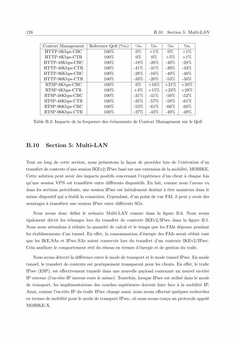
128 B.10. Section 5: Multi-LAN
Context Management Reference QoS (0/8s) 1/8s 2/8s 3/8s 4/8s
HTTP-8Kbps-CBC 100% 0% +1% 0% +1%HTTP-8Kbps-CTR 100% 0% 0% +5% +1%HTTP-48Kbps-CBC 100% -18% -20% -40% -28%HTTP-48Kbps-CTR 100% -41% -31% -39% -33%HTTP-96Kbps-CBC 100% -28% -16% -40% -48%HTTP-96Kbps-CTR 100% -33% -20% -53% -50%
RTSP-8Kbps-CBC 100% 0% +16% +21% +28%RTSP-8Kbps-CTR 100% +3% +15% +23% +28%RTSP-48Kbps-CBC 100% -31% -41% -50% -52%RTSP-48Kbps-CTR 100% -35% -57% -58% -61%RTSP-96Kbps-CBC 100% -53% -61% -66% -68%RTSP-96Kbps-CTR 100% -27% -43% -49% -49%
Table B.3: Impacte de la frequence des evenements de Context Management sur le QoS
B.10 Section 5: Multi-LAN
Tout au long de cette section, nous presentons la facon de proceder lors de l’execution d’un
transfert de contexte d’une session IKEv2/IPsec base sur une extension de la mobilite, MOBIKE.
Cette solution peut avoir des impacts positifs concernant l’experience d’un client a chaque fois
qu’une session VPN est transferee entre differents dispositifs. En fait, comme nous l’avons vu
dans les sections precedents, une session IPsec est initialement destine a etre maintenu dans le
meme dispositif qui a etabli la connexion. Cependant, d’un point de vue FAI, il peut y avoir des
avantages a transferer une session IPsec entre differents SGs.
Nous avons donc defini le scenario Multi-LAN comme dans la figure B.6. Nous avons
egalement decrit les echanges lors du transfert de contexte IKEv2/IPsec dans la figure B.5.
Nous nous attendons a reduire la quantite de calcul et le temps que les FAIs depense pendant
les etablissements d’un tunnel. En effet, la consommation d’energie des FAIs serait reduit tant
que les IKE SAs et IPsec SAs soient conserves lors du transfert d’un contexte IKEv2/IPsec.
Cela ameliore le comportement reel du reseau en termes d’energie et de gestion du trafic.
Nous avons detecte la difference entre le mode de transport et le mode tunnel IPsec. En mode
tunnel, le transfert de contexte est pratiquement transparent pour les clients. En effet, le trafic
IPsec (ESP), est effectivement tunnele dans une nouvelle payload contenant un nouvel en-tete
IP externe (l’en-tete IP interne reste le meme). Toutefois, lorsque IPsec est utilise dans le mode
de transport, les implementations des couches superieures doivent faire face a la mobilite IP.
Ainsi, comme l’en-tete IP du trafic IPsec change aussi, nous avons effectue quelques recherches
en termes de mobilite pour le mode de transport IPsec, ou nous avons concu un protocole appele
MOBIKE-X.

Appendix B. Resume etendu en Francais 129
@SG_IP1
@PEER_IP_ADDRESS
OLD IKEv2/IPsec Tunnel
INFORMATIONAL EXCHANGE
@PEER_IP_ADDRESS
@SG_IP2
@SG_IP1
IKEV2/IPSEC CONTEXT TRANSFER
@PEER_IP_ADDRESS
@SG_IP2
NEW IKEv2/IPsec Tunnel
@SG_IP2
3
1
2
Figure B.5: Multi-LAN IKEv2/IPsec context transfer

130 B.10. Section 5: Multi-LAN
@IP_SG3
END-USER
@IP_SGn
VPN Database
VPN Database
VPN Database
VPN Database
IPSEC TUNNELDATA FLOW
@IP_SG1 @IP_SG2
@IP_END_USER
CONTEXT TRANSFER
Figure B.6: Scenario of a Multi-LAN IKEv2/IPsec context transfer

Appendix B. Resume etendu en Francais 131
Les futurs travaux comprennent la mise en place du scenario Multi-LAN. Une nouvelle
prolongation du contrat de recherche a ete approuve mutuellement entre Orange (France
Telecom) et l’Universite de Paris 6, afin de poursuivre ce theme de recherche.
B.11 Conclusions et Perspectives
Cette these se concentre a garantir et ameliorer la continuite de service de communications bases
sur IKEv2/IPsec, principalement mis en œuvre dans les services VPN.
La premiere partie de notre investigation est porte sur la facon de proteger les reseaux IP avec
IPsec. Nous avons egalement introduit le concept de l’utilisation IKEv2 comme le complement
d’IPsec afin de proceder a l’authentification des nœuds et de la gestion ulterieure des connexions
IPsec. Cela permet aux operateurs d’offrir un environnement fiable et securise sur un reseau
non securise. En outre, en fournissant une extension IKEv2 du type MOBIKE ou REDIRECT,
nous pretendons presenter un cadre pour le transfert de contexte transparent afin de gerer
dynamiquement une session VPN.
Les etudes ulterieures nous sont amene a developper deux nouvelles fonctionnalites
concernant IKEv2/IPsec VPN: les fonctions GET et PUT. Notre motivation principale etait
de parvenir a une gestion dynamique d’une session VPN. Nous avons trouve que l’extraction
de toutes les informations concernant une session IKEv2/IPsec prendrait environ 15ms, et
que reinstaller ceux-ci prendrait environ 22ms. Nos developpements ont ete effectue sous
l’implementation Open Source de StrongSwan.
La deuxieme partie de la these a ete consacree a l’environnement Mono-LAN. Nous avons
etudie la mise en œuvre de ClusterIP, un mecanisme permettant de creer un cluster de SGs
configures sous une meme adresse IP virtuelle. Les resultats dans cette partie on montre
qu’une SG actif depense 5 % a 8 % de CPU plus qu’une SG passive lors du regroupement
des tunnels IPsec avec le mecanisme ClusterIP. Nous avons egalement constate qu’il y a une
charge supplementaire lors de l’utilisation du HA-plugin de strongSwan parmi les membres du
cluster. D’autres investigation nous sont amenes a fusionner ClusterIP avec nos propres fonctions
(GET et PUT). Nous avons cree un cadre de transfert de contexte IKEv2/IPsec transparente
pour les clients. Cela nous a conduit a la definition de deux nouvelles architectures offrant des
capacites differentes: gestion du trafic IPsec et l’haute disponibilite. Ceux-ci sont bases sur nos
implementations GET et PUT. Nous avons presente nos resultats en termes de comportement
du reseau et de la qualite de service. Lors des experimentes sous l’architecture de HA, nous
avons constate que le comportement du reseau des protocoles non-orientes a connexion (par
exemple, UDP) sont moins impactes par le basculement qu’un protocole oriente a connexion
(par exemple, TCP). En ce qui concerne les resultats du gestion du trafic, nous avons remarque
qu’en generale, cette architecture est moins impactee que les scenarios ou les fonctionnalites

132 B.11. Conclusions et Perspectives
HA sont actives. Tout au long de la deuxieme partie de la these, nous remarquons que ce type
de mecanismes permettrait d’effectuer de l’equilibrage de charge des sessions VPNs, ainsi que
d’effectuer de la repartition de charge entre les differents membres du cluster (sans besoin d’avoir
un dispositif dedie pour cela). Cependant, nous avons egalement constate que ces solutions sont
plus specifiques pour des groupes de nœuds situe localement, ou les SG sont places physiquement
proche les unes des autres, restant configures dans un meme segment de reseau.
En suite, la troisieme partie de la these a ete dediee aux environnements multi-LAN. Nous
avons defini une architecture pour le transfert des contextes IKEv2/IPsec entre SGs possedant
des adresses IP differentes. Bien que les deux modes d’IPsec, le mode tunnel et le mode transport,
impliquent une certaine signalisation IKEv2 (par un echange INFORMATIONAL) lors d’un
changement du point d’attachement, ils sont impactes differemment. Dans le mode tunnel,
lorsque l’adresse IP associee au l’une des extremites du tunnel change, cette interruption est
completement transparente pour les applications des couches superieures. Meme si l’adresse IP
externe d’un tunnel change, l’adresse IP interne du tunnel reste le meme. Par contre, pour les
communications en mode transport, il n’y a pas d’adresse IP interne. Les couches superieures
devront faire face a la mobilite IP a chaque fois que son adresse IP associe a une IKE SA
et IPSec SA change. Nos efforts se concentrent a permettre l’operateur a deplacer un client a
partir d’une SG vers une autre. Tout cela, en utilisant une signalisation minimale, moins de
consommation et moins de calcul associee a la construction du materiel cryptographique.
Evolution Globale et travail a venir
Comme la plupart des terminaux sont a nous jours equipes avec des interfaces reseau d’acces
alternatifs (par exemple WiFi), nous pensons que les operateurs doivent se concentrer sur la
facon dont ils peuvent etre utilises pour acceder aux services. D’autre part, l’une des evolutions
possibles pour permettre la circulation a partir de reseaux d’acces mobiles est de decharger le
trafic reseau d’acces radio (RAN) vers des reseaux d’acces complementaires tels que le WIFI,
WIMAX, femtocells, etc. Ces reseaux sont appeles a maintenir le meme niveau de securite aussi
bien que les RANs. En outre, les reseaux d’acces non mobiles, comme le WiFi, sont tres repandus
comme des extensions de reseaux sans fil a haut debit, principalement dans les espaces interieurs
ou les technologies cellulaires ne fonctionnent pas bien.
Les FAI sont interesses a offrir de nouvelles fonctionnalites a ses services VPNs. Meme si
le contenu multimedia d’aujourd’hui sont principalement offerts par les services Web (HTTP
streaming, VoIP, etc), l’acces au reseau lui-meme est toujours gere par les FAI. Les operateurs
doivent etre capables de s’adapter facilement a de nouvelles opportunites. Par exemple, en
sachant ses choix au niveau de l’architecture du reseaux, un FAI tel qu’Orange peut proposer
NaaS (reseau en tant que service) des services a l’avenir, ce qui necessite la mise en œuvre des
VPN. Par consequent, l’amelioration de la fiabilite, la disponibilite et la qualite de ces services
est une question d’interet.

Appendix B. Resume etendu en Francais 133
Comme indique tout au long de cette these, le trafic de donnees mobiles est en croissance
permanente et annuelle (60% a 70%). Mis a part de la croissance du trafic, il y a eu aussi
la generalisation des plans de facturation forfaitaire, une plus de la grande disponibilite de
contenus attractifs ainsi que la la disponibilite croissante des appareils de grande consommation
(par exemple, ordinateurs portables, smartphones, tablettes, etc.). Tout ce contexte cree une
forte pression sur les operateurs pour qu’ils donnent la meilleur performance possible de leurs
reseaux.
Nos propres developpements dans ce domaine nous permettent de gerer un tunnel VPN.
Ceux-ci permettent a un operateur de gerer dynamiquement le EUs qui utilisent ses services
VPN et avoir un impact positif sur leurs experience et qualite de service. Cependant, il reste
encore du travail afin de faire integrer ceux-ci a l’interieur des reseaux operationnelles.
Tout d’abord, meme si nos bancs d’essai concernant les environnements mono-LAN
considerais le transfert du contexte IKEv2/IPsec entre deux SG differentes, nous croyons qu’il
est important de definir un algorithme qui decide la responsabilite des paquets entrants vers un
cluster compose par n nœuds. Pour les scenarios de haute disponibilite, nous avons aborde les
scenarios actifs/passifs, mais pour le partage de charge ou des scenarios d’equilibrage de charge,
il serait important de definir cet algorithme qui deciderait comment repartir la charge entre les
differents membres du cluster.
En ce qui concerne les environnements multi-LAN, nous avons presente une solution basee
sur MOBIKE permettant d’effectuer le transfert de contexte. Cette solution resout le cadre
d’un contexte IKEv2/IPsec entre les nœuds avec une adresse IP differente. Comme la periode
de la these touchais a sa fin, cette mise en place fait partie des travaux futurs de ma these.
Cependant, un projet tres motivant emerge afin de poursuivre nos recherches dans ce domaine.
Une fois les developpements de Multi-LAN sont faites, nous pretendons donner a la communaute
un mecanisme qui ameliore le comportement du reseau. En fait, les futurs reseaux ont tendance a
etre plus heterogene, et ce mecanisme permettrait de transferer une session VPN entre differents
dispositifs. En outre, on pretend reduire les retards de retablir un nouveau tunnel VPN vers un
nouveau dispositif, au lieu de transferer ces donnees entre les dispositifs entre eux-meme.
Il peut etre important de concentrer les efforts a definir une sorte d’intelligence locale afin
de gerer les sessions IKEv2/IPsec. Une sorte d’application capable d’externaliser la decision de
la gestion des sessions. Par exemple, un cas d’utilisation serait un gestionnaire de connexions
afin de decider d’effectuer un transfert de contexte, des fonctions de mobilite ou multihoming,
ou de gerer dynamiquement les aspects de securite. Comme IKEv2 est le protocole permettant
de negocier des modifications a IPsec, le gestionnaire de connexions serait en mesure de donner
des ordres afin de personnaliser une session IKEv2/IPsec active.
Aujourd’hui, les reseaux sont composes de plusieurs technologies d’acces, ou chacun definit

134 B.11. Conclusions et Perspectives
ses propres normes de securite, introduisant plus d’heterogeneite dans le reseau Internet.
Cette situation presente l’inconvenient qu’il est complexe a maintenir le meme niveau de
securite entre les differentes technologies d’acces au reseau, ce qui peut inclure differents
appareils (constructeurs). Cependant, les communcation de radio ont desormais migre vers les
communications en IP. Cela nous permet de proposer IPsec en tant que mecanisme de securite
sur tout le reseau. Notre interet est de poursuivre nos investigations dans le but d’introduire
des mecanismes plus sophistiques qui permettent de maintenir le meme niveau de securite
independamment de la technologie d’acces. Nous pretendons proposer un projet au sein de
l’IETF afin de pousser la standardisation vers le transfert de contexte IPsec.

Accomplished Work
Publications
The results of this thesis, are reflected in some publications and contributions. We are also
currently working on publishing the code for the open source community. Publications include:
- D. Palomares, D. Migault, and M. Laurent, ”Failure Preventive Mechanism for IPsec
Gateways”, in International Conference on Communications and Information Technology
- ICCIT 2013, Beirut - Lebanon.
- D. Palomares, D. Migault and M. Laurent ”Mechanisms to ensure continuity of service for
IKEv2/IPsec based communications”, in International Conference on Secure Networking
and Applications - ICSNA 2011, Paris - France.
- D. Palomares, D. Migault, W. Velasquez and M. Laurent ”High Availability for IPsec
VPN Platforms - ClusterIP Evaluation”, in 8th International Conference on Availability,
Reliability and Security ARES 2013, Regensburg - Germany.
Contributions as co-author
- D. Migault, D. Palomares, E. Herbert, W. You, G. Ganne, G. Arfaoui and M. Laurent,
”E2E: An Optimized IPsec Architecture for Secure And Fast Offload”, in 7th International
Conference on Availability, Reliability and Security, ARES 2012, Prague - Czech Republic.
- Migault, D., Palomares, D., Herbert, E., You, W., Arfaoui and Laurent, M, ”ISP Offload
Infrastructure to minimize cost and time deployment”, GLOBCOM 2012, Anaheim, CA,
USA.
- [32,37,38] are contribution for MOBIKE-X at the IETF.
135

136 B.11. Conclusions et Perspectives
Pieces of Software
Source code includes:
- GET and PUT functions. This implementation is based on strongSwan 4.5.0.
- IPsec-CTX form guide lines for Mono-LAN environments on a Wiki.
- A set of scripts used to perform context transfer tests for all the testbeds presented
throughout this thesis.
- A webpage with some tools and explanation of our work (this web site is currently under
construction).

Acronyms and Definitions
EU End User
HA High Availability
IKEv2 Internet Key Exchange, version 2
IKE SA IKE Security Association
IPsec Internet Protocol security
IPsec SA IPsec Security Association
IPsec-CXT IPsec context transfer
MN Mobile Node
MIP Mobile IP
SA Security Association
SG Security Gateway
VPN Virtual Private Network
WLAN Wireless Local Area Network
137

138

Bibliography
[1] Cisco. (2013) Cisco visual networking index: Global mobile data traffic forecast update,
2012–2017. [Online]. Available: http://www.cisco.com/en/US/solutions/collateral/ns341/
ns525/ns537/ns705/ns827/white paper c11-520862.html
[2] S. Kent and K. Seo, “Security Architecture for the Internet Protocol,” RFC 4301
(Proposed Standard), Internet Engineering Task Force, Dec. 2005, updated by RFC 6040.
[Online]. Available: http://www.ietf.org/rfc/rfc4301.txt
[3] P. Eronen, “IKEv2 Mobility and Multihoming Protocol (MOBIKE),” RFC 4555
(Proposed Standard), Internet Engineering Task Force, Jun. 2006. [Online]. Available:
http://www.ietf.org/rfc/rfc4555.txt
[4] V. Devarapalli and K. Weniger, “Redirect Mechanism for the Internet Key Exchange
Protocol Version 2 (IKEv2),” RFC 5685 (Proposed Standard), Internet Engineering Task
Force, Nov. 2009. [Online]. Available: http://www.ietf.org/rfc/rfc5685.txt
[5] M. Georgiades, H. Wang, and R. Rafazolli, “Security of context transfer in future wireless
communications,” in Wireless World Research Forum (WWRF), Toronto, Canada, Nov
2004.
[6] S. Ayaz, C. Bauer, and M. Ehammer, “Applying IKE/IPsec Context Transfer to
Aeronautical Networks,” in 7th ACM international symposium on Mobility management
and wireless access (MobiWAC ’09), 2009.
[7] J. Loughney, M. Nakhjiri, C. Perkins, and R. Koodli, “Context Transfer Protocol
(CXTP),” RFC 4067 (Experimental), Internet Engineering Task Force, Jul. 2005. [Online].
Available: http://www.ietf.org/rfc/rfc4067.txt
[8] F. Allard, “Le transfert de contexte : atout pour la mobilite et outil de reduction des
couts pour la securite,” Ph.D. dissertation, RSM - Dept. Reseaux, Securite et Multimedia
(Institut Mines-Telecom-Telecom Bretagne-UEB), 2009.
139

140 Bibliography
[9] V. Devarapalli and F. Dupont, “Mobile IPv6 Operation with IKEv2 and the Revised
IPsec Architecture,” RFC 4877 (Proposed Standard), Internet Engineering Task Force,
Apr. 2007. [Online]. Available: http://www.ietf.org/rfc/rfc4877.txt
[10] F. Allard and J.-M. Bonnin, “An application of the context transfer protocol : IPsec
in a IPv6 mobility environment,” International journal of communication networks and
distributed systems, vol. 1, no. 1, pp. 110 – 126, 2008.
[11] F. Allard, J.-M. Bonnin, J.-M. Combes, and J. Bournelle, “IKE Context Transfer in an
IPv6 Mobility Environment,” in MobiArch’08, 22 aout, Seattle (WA), USA. FT - France
Telecom, Division R&D, Issy Les Moulineaux (France Telecom), RSM - Dept. Reseaux,
Securite et Multimedia (Institut Mines-Telecom-Telecom Bretagne-UEB), 2008.
[12] F. Allard, J.-M. Combes, R. M. Lopez, and A. G. Skarmeta, “Security Analysis and Security
Optimizations for the Context Transfer Protocol,” in NTMS’08 : second International
Conference on New Technologies, Mobility and Security, 5-7 novembre, Tanger, Maroc. FT
- France Telecom, Division R&D, Issy Les Moulineaux (France Telecom), UMU - University
of Murcia, 2008.
[13] F. Allard and J.-M. Bonnin, “An application of the context transfer protocol : IPsec in a
IPv6 mobility environment,” in BWIA’07 : International workshop on Broadband wireless
Internet access, 21 aout, Ottawa (ON), Canada. FT - France Telecom, Division R&D, Issy
Les Moulineaux (France Telecom), RSM - Dept. Reseaux, Securite et Multimedia (Institut
Mines-Telecom-Telecom Bretagne-UEB), 2007.
[14] F. Allard, “Etude de faisabilite concernant le transfert de contexte pour la securite,” in
GRES’06, 9-12 mai, Bordeaux, France. FT - France Telecom, Division R&D, Issy Les
Moulineaux (France Telecom), 2006.
[15] R. Singh, G. Kalyani, Y. Nir, Y. Sheffer, and D. Zhang, “Protocol Support for High
Availability of IKEv2/IPsec,” RFC 6311 (Proposed Standard), Internet Engineering Task
Force, Jul. 2011. [Online]. Available: http://www.ietf.org/rfc/rfc6311.txt
[16] A. Steffen., “the OpenSource IPsec-based VPN Solution: StrongSwan.” [Online]. Available:
http://www.strongswan.org
[17] POLQA, “Perceptual Objective Listening Quality Assessment - POLQA.” [Online].
Available: http://www.polqa.de
[18] D. Palomares, “Mechanisms to Ensure Continuity of Service for IPsec/IKEv2 Based
Communications,” in ICSNA-2011: International Conference on Secure Networking and
Applications ,24-25 October, Paris, France. FT - France Telecom, Division R&D, Issy Les
Moulineaux (France Telecom), 2011.

Bibliography 141
[19] D. Palomares, D. Migault, and M. Laurent, “Failure Preventive Mechanism for IPsec
Gateways,” in International Conference on Communications and Information Technology -
ICCIT’13, 2013.
[20] D. Migault, D. Palomares, E. Herbert, W. You, G. Ganne, G. Arfaoui, and M. Laurent,
“E2E: An Optimized IPsec Architecture for Secure And Fast Offload,” in International
Workshop on Security of Mobile Applications IWSMA’12 (co-located with ARES’12), Aug.
2012.
[21] D. Migault, D. Palomares, E. Herbert, W. You, G. G. G. Arfaoui, and M. Laurent, “ISP
Offload Infrastructure to minimize cost and time deployment,” in Proceedings of IEEE
Global Telecommunications Conference - Communication and Information System Security
(GLOBECOM ’12), Dec. 2012.
[22] ITU, Security architecture for Open Systems Interconnection for CCITT applications
(ITU-T Recommendation X.800), International Telecommunications Union, Mar. 1991.
[23] S. Kent, “IP Authentication Header,” RFC 4302 (Proposed Standard), Internet Engineering
Task Force, Dec. 2005. [Online]. Available: http://www.ietf.org/rfc/rfc4302.txt
[24] S. Kent and R. Atkinson, “IP Encapsulating Security Payload (ESP),” RFC 2406
(Proposed Standard), Internet Engineering Task Force, Nov. 1998, obsoleted by RFCs
4303, 4305. [Online]. Available: http://www.ietf.org/rfc/rfc2406.txt
[25] C. Kaufman, “Internet Key Exchange (IKEv2) Protocol,” RFC 4306 (Proposed Standard),
Internet Engineering Task Force, Dec. 2005, obsoleted by RFC 5996, updated by RFC
5282. [Online]. Available: http://www.ietf.org/rfc/rfc4306.txt
[26] C. Kaufman, P. Hoffman, Y. Nir, and P. Eronen, “Internet Key Exchange Protocol Version
2 (IKEv2),” RFC 5996 (Proposed Standard), Internet Engineering Task Force, Sep. 2010,
updated by RFC 5998. [Online]. Available: http://www.ietf.org/rfc/rfc5996.txt
[27] D. Piper, “The Internet IP Security Domain of Interpretation for ISAKMP,” RFC 2407
(Proposed Standard), Internet Engineering Task Force, Nov. 1998, obsoleted by RFC
4306. [Online]. Available: http://www.ietf.org/rfc/rfc2407.txt
[28] D. Maughan, M. Schertler, M. Schneider, and J. Turner, “Internet Security Association
and Key Management Protocol (ISAKMP),” RFC 2408 (Proposed Standard), Internet
Engineering Task Force, Nov. 1998, obsoleted by RFC 4306. [Online]. Available:
http://www.ietf.org/rfc/rfc2408.txt
[29] D. Harkins and D. Carrel, “The Internet Key Exchange (IKE),” RFC 2409 (Proposed
Standard), Internet Engineering Task Force, Nov. 1998, obsoleted by RFC 4306, updated
by RFC 4109. [Online]. Available: http://www.ietf.org/rfc/rfc2409.txt

142 Bibliography
[30] H. Tschofenig, D. Kroeselberg, A. Pashalidis, Y. Ohba, and F. Bersani, “The Extensible
Authentication Protocol-Internet Key Exchange Protocol version 2 (EAP-IKEv2) Method,”
RFC 5106 (Experimental), Internet Engineering Task Force, Feb. 2008. [Online]. Available:
http://www.ietf.org/rfc/rfc5106.txt
[31] M. Devera, “HTB Linux queuing discipline manual - user guide.” [Online]. Available:
http://luxik.cdi.cz/∼devik/qos/htb/manual/userg.htm
[32] D. Migault, “MOBIKE eXtension (MOBIKE-X) for Transport Mobility and Multihomed
IKE SA,” (Work in Progress), Internet Engineering Task Force, Sep. 2009. [Online].
Available: http://www.ietf.org/html/draft-mglt-ipsec-mm-mobikex-00
[33] S. Frankel and S. Krishnan, “IP Security (IPsec) and Internet Key Exchange (IKE)
Document Roadmap,” RFC 6071 (Informational), Internet Engineering Task Force, Feb.
2011. [Online]. Available: http://www.ietf.org/rfc/rfc6071.txt
[34] 3GPP-LTE, “3gpp system to wireless local area network (wlan) interworking; system
description, ts 23.234, release 10,” Standard, Mar. 2011.
[35] L. Yu, S. Jia, C. Xu, J. Guan, and D. Gao, “An ipsec seamless switching mechanism with
high availability and scalability by extending ikev2 protocol,” IET Conference Publications,
vol. 2011, no. CP588, 2011.
[36] Y. Nir, “IPsec Cluster Problem Statement,” RFC 6027 (Informational), Internet
Engineering Task Force, Oct. 2010. [Online]. Available: http://www.ietf.org/rfc/rfc6027.txt
[37] D. Migault, “IPsec mobility and multihoming requirements : Problem statement,”
(Work in Progress), Internet Engineering Task Force, Sep. 2009. [Online]. Available:
http://www.ietf.org/html/draft-mglt-ipsec-mm-requirements-00
[38] D. Migault and C. Williams, “Multiple Interfaces IPsec Security Requirements,”
(Work in Progress), Internet Engineering Task Force, Mar. 2012. [Online]. Available:
https://datatracker.ietf.org/doc/draft-mglt-mif-security-requirements/
[39] Wikipedia, “Boxplot — Wikipedia The Free Encyclopedia.” [Online]. Available:
http://en.wikipedia.org/wiki/Box plot
[40] J. Kempf, “Problem Description: Reasons For Performing Context Transfers Between
Nodes in an IP Access Network,” RFC 3374 (Informational), Internet Engineering Task
Force, Sep. 2002. [Online]. Available: http://www.ietf.org/rfc/rfc3374.txt
[41] R. Hinden, “Virtual Router Redundancy Protocol (VRRP),” RFC 3768 (Draft Standard),
Internet Engineering Task Force, Apr. 2004, obsoleted by RFC 5798. [Online]. Available:
http://www.ietf.org/rfc/rfc3768.txt

Bibliography 143
[42] R. Housley, “Using Advanced Encryption Standard (AES) Counter Mode With
IPsec Encapsulating Security Payload (ESP),” RFC 3686 (Proposed Standard), Internet
Engineering Task Force, Jan. 2004. [Online]. Available: http://www.ietf.org/rfc/rfc3686.txt
[43] D. W. Helger Lipmaa, Phillip Rogaway, “Comments to NIST concerning AES Modes of
Operations: CTR-Mode Encryption,” in Workshop. University of California Berkeley,
2010.
[44] VLC, “VLC streaming protocols.” [Online]. Available: http://www.videolan.org/
streaming-features.html
[45] Arecord, “Arecord native ALSA command.” [Online]. Available: http://alsa.opensrc.org/
Arecord
[46] J. P. Richard Reynolds, “Application Guide for Recommendation ITU T P.863.” [Online].
Available: http://www.itu.int/ITU-T/workprog/wp item.aspx?isn=8909