Embed Size (px)
Citation preview
Study of New Welding Tubular Joint Used For Jacket
S.H. Xu & F.Y. Yang & L.Q. Jiang & M.W. Gu & Z.R. Song & D.W. Yao & Q.G. Liu
China Offshore Oil Engineering (Qingdao) Co. Ltd. Qingdao, Shandong, China
KEYWORD: Build-up, welding, tubular joint, assembly ABSTRACT: As the stronger desire of human for energy and space, offshore jackets are used more and more for these. As the excellent fluid mechanics feature of the tubular member, it is widely used in jacket structures. According to the introduction of the process of casting steel joint and directly weld joint, this page expounds the advantages and disadvantages of them and put forward a new style welded tubular joint. This paper also gives some advises on dimension control and reducing re-sidual stress. All this contribute to a new way for the building of tubular joint of jacket or other simi-lar structures. By integrating the advantages of casting steel joint and directly weld joint, a new type welded tubular joint was developed with the build-up welding. It is easily to assemble and has low residual stress. Because of its integrity, failure probability will be reduced by using this kind tubular joint in jacket.
INTRODUCTION As the energy and space onshore is almost fully developed in some place, the desire for energy and space becomes stronger day by day and someone has put it into practice. At the same time, the span of the offshore structures become bigger and bigger and they consume more and more steel. Because of the excellent mechanism in marine environment, the study of tubular joint is in the ascendant. By the comparing of fabrication process of directly welded tubular joint and casting steel joint, this pa-per develops a new welded tubular joint which can be used in jacket and other structures.
DIRECTLY WELDED TUBULAR JOINT
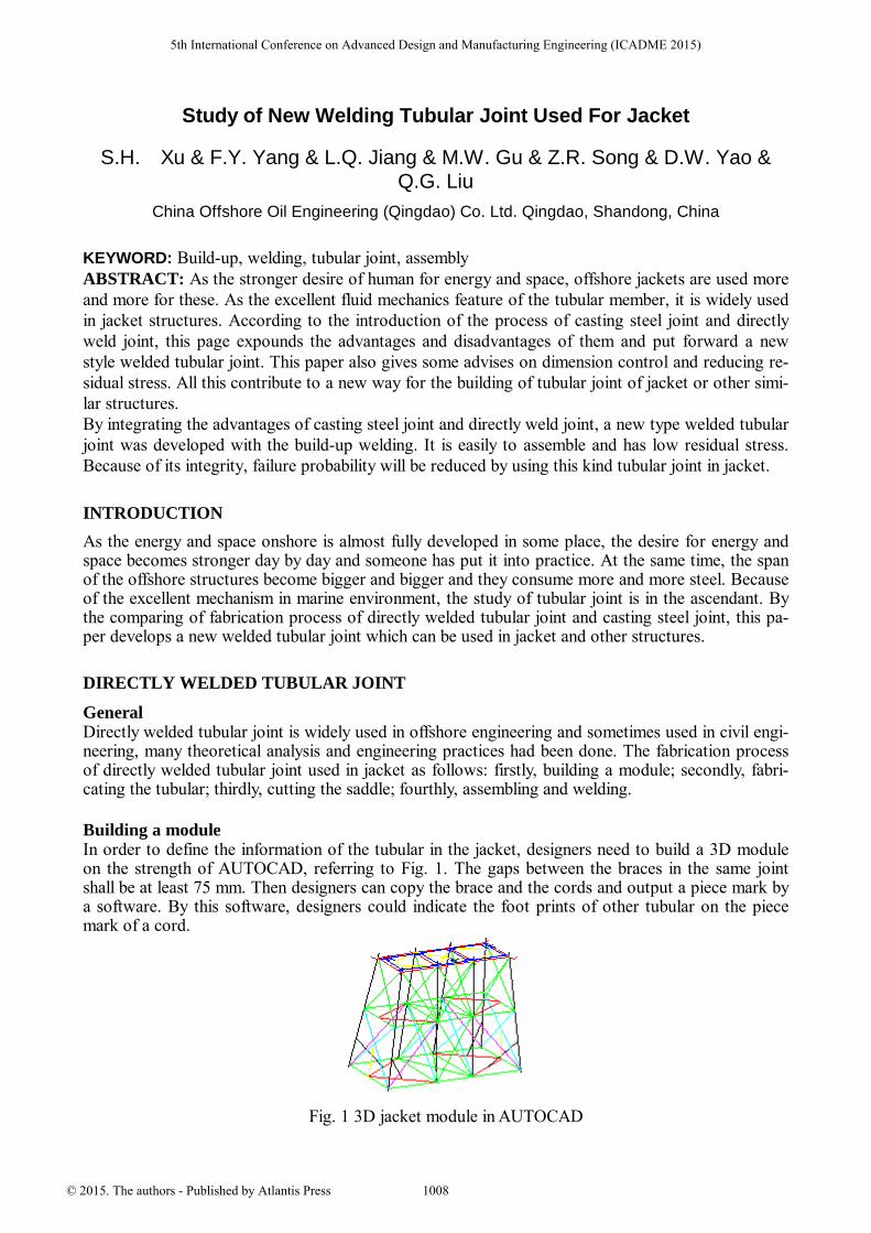
General Directly welded tubular joint is widely used in offshore engineering and sometimes used in civil engi-neering, many theoretical analysis and engineering practices had been done. The fabrication process of directly welded tubular joint used in jacket as follows: firstly, building a module; secondly, fabri-cating the tubular; thirdly, cutting the saddle; fourthly, assembling and welding. Building a module In order to define the information of the tubular in the jacket, designers need to build a 3D module on the strength of AUTOCAD, referring to Fig. 1. The gaps between the braces in the same joint shall be at least 75 mm. Then designers can copy the brace and the cords and output a piece mark by a software. By this software, designers could indicate the foot prints of other tubular on the piece mark of a cord.
Fig. 1 3D jacket module in AUTOCAD
5th International Conference on Advanced Design and Manufacturing Engineering (ICADME 2015)
© 2015. The authors - Published by Atlantis Press 1008

Fabricating the tubular For the tubular which O.D. (outer diameter) less than 406 mm, seamless hot rolled and cold drawn steel tubular can be produced in the steel mill. So a material order list to the steel mill which provides the seamless tubular may be a good choice. For the tubular which O.D. equal to or greater than 406 mm, it can be rolled by the veneer reeling machine, JCO may be another choice. But not all the tubu-lar which O.D. is equal to or greater than 406 mm can be fabricated in this way. Referring to DNV-OS-C401, the plastic deformation shall be less than 5%. If the deformation exceeds 5%, either heat treatment or strain ageing tests shall be carried out according to an agreed procedure. The plastic de-formation (e) may be calculated referring to Eq. 1.
e 100%tD
= (1)
t = material thickness D = outside diameter of pipe or vessel
Referring to API 2B, girth, radial offset of abutting edges of the girth seams shall not exceed 0.2T (where T is the wall thickness) or 1/4 in. radial offset of abutting edges of longitudinal weld seams shall not exceed 1/8 in. After the fabrication of the tubular cans, then the cans shall be assembled to the nominal length. Cutting the saddle Referring to Fig. 2, saddle cutting is always done by a special machine, but tubular whose outside di-ameter greater than 2000 shall be cut by manual. In this process, engineers need to prepare a welding bevel, referring to AWS D1.1.
Fig. 2 template of saddle with welding bevel
Assembling & welding On the basis of relative location of the nodes which define a tubular member, the braces and their cords will be assembled together and form a welded tubular joint, referring to Fig. 3.
Fig. 3 a directly welded joint
1009

CASTING STEEL TUBULAR JOINT
General The cast steel joint is a casting formed by pouring the liquid steel into the mold based on the model-ing of a fixed tubular joint. In the engineering circles, especially in Japan and European Union, cast-ing joint is widely used in the civil engineering. Refer to the offshore field, Japan managed to use casting steel joint in the jacket serving in the North Sea in 1985. The production process of the cast-ing joint mainly include: casting, heat treatment and the finishing. Material Selection of Cast Steel Joint In the engineering practices, welding connections widely exist between the cast joint and the tubular cans. So it is essential to try best to make the chemical composition of the cast joint nearly the same as the chemical composition of the tubular cans. In the casting process, the chemical composition shall be strictly controlled. The cast members are mainly of two kinds: the cast carbon steel member and the cast high strength low alloy steel members. For the cast carbon steel member, due to harden ability, inferior mechanical properties and the member of large section cannot be strengthened by heat treatment, and it is rarely used in cast members. The high strength low alloy steel, as its high strength, great plasticity, great toughness and good welding ability, is widely accepted in steel structure works. Casting Process of Cast Steel Joint The process of casting is not very difficult to understand. Referring to Fig. 4, the key steps of the casting process are the mould design, producing and the melting. The joint includes one brace and several braces and may be added with some stiffeners, what is more, the braces may have offsets or overlaps. These will make the tubular joint to be a complex mould, and the sections and angle shall be very accurate. The melting process is very important as it decides the chemical composition which will impact the welding ability and mechanical properties of the casting steel joint.
Fig. 4 casting process
Heat Treatment of Cast Steel Joint Interdendritic segregation, uneven texture, coarse grain, network structure and other problems usual-ly existed in the microstructure of cast steel, so heat treatment is essential to improve its mechanical properties. At the same time, as the thickness and section changes and different texture at different parts, residual stress exists in the cast members. In order to improve the mechanical properties and induce the residual stress produced in the casting process, the heat treatment of cast steel joint as a whole is needed. The heat treatment is handling in a gas heat furnace which temperature is under control.
1010

The cast steel joint used in offshore structures is usually in +QT (quenching & tempering) heat treatment conditions for its better welding ability. Finishing of Cast Steel Joint The finishing process of the cast steel joint mainly include: cleaning of the sand, cutting the feeder, repairing welding, grinding, shot blasting, anti-corrosion treatment. After the polishing of the cast steel joint, it can be delivered for engineering, and a finishing cast steel joint is as shown in Fig. 5.
Fig. 5 a cast steel tubular joint
STUDY OF TUBULAR JOINT
Bearing Capacity Test The study approaches of the tubular joint bearing capacity have been gradually matured, and many achievements are taken by many design rules. Bearing capacity test is most effective analysis ap-proach, and the testing results can be directly used in engineering application. However, the bearing capacity test costs so much and taken a long time. At the same time, the complex boundary condi-tions of the tubular joint are hardly to rebuild or simulate. Value Simulation Technology
With the quick development of computer technology and value simulation technology, software of finite element analysis based on the third strength theory has become to a critical approach for the study of tubular joints. Up to now, though static bearing load studies for intersecting tubular joints have gain great progress, comparing to complex engineering structure and load condition, value si-mulation technology still has many disadvantages.
No matter what kind of analysis method, a tubular joint will be regarded as superior if it has these characteristics: low stress centralization, less residual stress, high dimension accuracy and so on.
NEW WELDING TUBULAR JOINT
Disadvantages of Directly Weld Tubular Joint and Cast Tubular Joint The disadvantages of the directly welding tubular joint as follows: stress concentration in the welding pass, high residual stress in the members, hash technical requirement in the fabrication and assembly process, great difficulties of fabrication when the braces overlap each other.
The disadvantages of the cast tubular joint are as follows: the big self-weight and high cost; so many kinds of modules; there is no way for mass production in the workshop; the carbon content is too high for engineering and the inferior though thickness properties; the defects in the production process which make mechanical properties not so good as hot rolled steel products.
1011
New Welding Tubular Joint On the strength of the contrastive analysis of the advantages and disadvantages of the directly welded and the cast tubular joint, this paper puts forward a new approach to build the tubular joint, which is called new welding tubular joint.
It takes advantage of the fabrication process of two approaches. Basing on the build-up welding technology, it combines the texture of the hot rolled products with the advanced manufacturing process of casting process.
The advantage of this approach is that the joint can be entirely fabricated in the any workshop avail-able. On the strength of this, there is no need to weld the saddle weld pass in the yard. The members in the yard are only joints and tubular cans, these can be easily assembled together. So the skidway or the yard shall be more effective. Besides, the joint can be fabricated in the workshop as automobile, so the quality can be better assured. The new welding tubular joint can be cheaper and cost less than the cast joint, for the cast joint need more steel and more complex process. At the same time, directly weld joint shall be welded together in the yard, it cost more time to finish the saddle welding pass and should get poor dimensions as the harsh climate. Material Selection of New Joint The new joint mainly take offshore structure steel plates and seamless tubular for small O.D. mem-bers. The material shall be selected as shown in Table 1.
Table 1, Material selection recommendation Country Technical speci-
fication United Kingdom BS7191 European Union EN10225 Norway NORSOK The United
States API
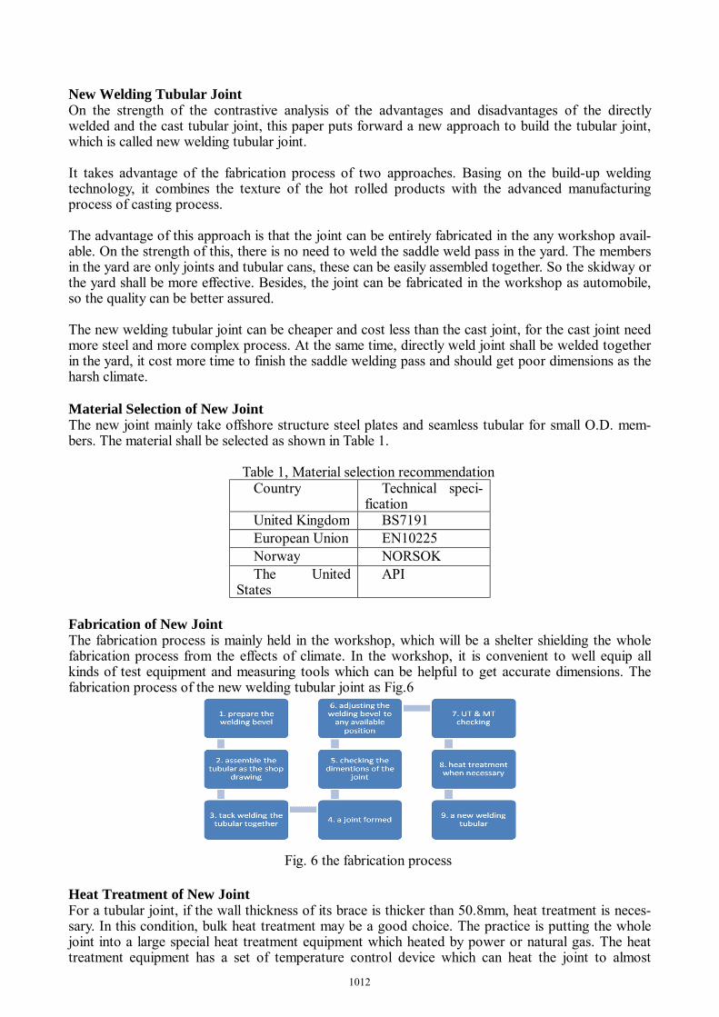
Fabrication of New Joint The fabrication process is mainly held in the workshop, which will be a shelter shielding the whole fabrication process from the effects of climate. In the workshop, it is convenient to well equip all kinds of test equipment and measuring tools which can be helpful to get accurate dimensions. The fabrication process of the new welding tubular joint as Fig.6
Fig. 6 the fabrication process
Heat Treatment of New Joint For a tubular joint, if the wall thickness of its brace is thicker than 50.8mm, heat treatment is neces-sary. In this condition, bulk heat treatment may be a good choice. The practice is putting the whole joint into a large special heat treatment equipment which heated by power or natural gas. The heat treatment equipment has a set of temperature control device which can heat the joint to almost
1012

580˚C, then keep this temperature range for a fixed time, at last cool down slowly. Relative to the now used local ( only the welding pass ) heat treatment, the bulk heat treatment can release 80%~90% of the residual stress.
Furthermore, in the node location, stiffen rings are usually designed to strength the chord. For this kind parts, cast joint and the directly welding joint cannot well tackle the distortion or the residual stress, nevertheless bulk heat treatment can handle it easily. Assembly of New Joint The new welding tubular joint shall be fixed at the theoretic location via the measuring system which is formed by All Station Instrument. Then the tubular cans shall be put in the gap between the joints. As the locations of joints are accurate, we just need to control the straightness of the tubular cans and the mismatch between the joints and the tubular cans, the jacket can get accurate overall dimen-sions.
The new joint also can be directly assembled to the jacket panel. As the joint had been entirely com-pleted, there is no need to weld these complex saddle welding passes, a comment tubular bevel weld can make the joint and the tubular cans together. This approach reduces the welding difficulty level form 6GR to 6G, so the quality of the welding pass can be better assured.
CONCLUSIONS Nowadays, as the offshore and large-span onshore structures are in the ascendant, a growing number of tubular joint are needed. At the same time, as the continual development of welding technology and rapid prototyping technology (or 3D printing technology), the fabrication of the new welding tubular joint will be cost-effective and rapid. The simple approach of fabrication, the accurate dimension and perfect mechanical properties of the new welding tubular joint will attract more attention and further study. The new welding tubular joint will serve in more and more offshore and large-span structures.
REFERENCES [1] API 2B (2007) Specification for the Fabrication of Structural Steel Pipe, American Petroleum
Institute, sixth edition [2] AWS D1.1 (2010) Structural Welding Code-Steel, American Welding Society, 22nd edition [3] DNV-OS-C401 (2014) Fabrication and Testing of Offshore Structures, Det. Norske Veritas, The
third edition
1013