Embed Size (px)
Citation preview
648
Study of the Aero-Acoustic and Aerodynamic Effects of
Soft Coating upon Airfoil∗
János VAD∗∗, Gábor KOSCSÓ∗∗, Miklós GUTERMUTH∗∗,Zsolt KASZA∗∗, Tamás TÁBI∗∗ and Tibor CSÖRGO∗∗∗
Comparative acoustic and wind tunnel experiments were carried out on uncoated andcoated isolated airfoils. The aim of the tests was to survey the airfoil noise reducing effectand the aerodynamic impact of the acoustically soft coating consisting of filaments, as apreliminary study in application of such coatings to axial flow turbomachinery bladings. Itwas found in the acoustic tests that the coating successfully reduces the sound pressure inthe frequency range critical from the aspect of human audition. The wind tunnel experimentsincluded laser Doppler anemometer studies on the development of the boundary layers andon the wake structure, and static pressure measurements on the blade surface and in the wake.The coating reduced the lift and increased the drag. A proposal has been made for furtherstudies in order to retain the advantageous acoustic effects of the coating while avoiding theundesirable aerodynamic impact.
Key Words: Axial Flow Turbomachinery, Fan Noise, Airfoil Aerodynamics, Wind TunnelTests, LDA Measurements, Flow Generated Noise
1. Introduction
The reduction of aerodynamic noise of axial flow fanshas been the subject of extensive research activity in thepast decades. Realization of the required performancewith rotors of reduced circumferential speed, diameter,and losses, i.e. development of methods to design highlyefficient fans of high specific performance(1) is a basicmeans of reducing turbofan noise. The rotor noise can besuppressed e.g. by reducing the relative tip clearance(2),but this may lead to problems in practical applications.Successful reduction of tip clearance-flow generated noiseand interaction noise can be carried out e.g. by means ofnon-radial blade stacking, i.e. sweep(3) and skew(4). Thenoise generated by the inlet turbulence on the blades canbe moderated by reducing the turbulence-generating ef-fects upstream of the rotor. The blade boundary layer(BL) noise and the wake noise are usually diminished if
∗ Received 17th January, 2006 (No. 05-5142)∗∗ Department of Fluid Mechanics, Budapest University of
Technology and Economics, Bertalan Lajos u. 4–6, H-1111 Budapest, Hungary. E-mail: [email protected]
∗∗∗ Department of General Zoology, Eotvos Lorand Uni-versity, Pazmany Peter setany 1/C, H-1117 Budapest,Hungary
the aerodynamic losses of the blade are minimized(5), forexample, with use of controlled diffusion profiles(6).
The above solutions mostly influence the constructionand geometry of the machinery. Beside these efforts, otherways are being sought for the production of silent fans.One solution could be the appropriate formation of bladesurface roughness elements or special blade surface struc-tures. It is known that the surface treatment has an impacton the aerodynamic characteristics. However, the impactof such a treatment on the noise of airfoils or of axial fanblades has been less investigated.
The blades of an axial flow fan operate in cascade(blade row) arrangement. However, if the solidity (bladechord-to-spacing ratio) of an axial flow blade row is rela-tively low — as in the case of several industrial fans(7)—,the operation of a blade section is considered to be analo-gous to that of an isolated airfoil(4). This gives the idea tosearch for cases in the animal world in which airfoil-likeaerodynamic growths such as bird wings operate silentlydue to their special surface characteristics; and to attemptadopting such characteristics to turbomachinery blades fornoise reduction.
Figure 1 shows the enlarged photographs of owl wingsurface sections and feathers. As the figure illustrates,owls(8) have small feathers equipped with filaments near
Series C, Vol. 49, No. 3, 2006 JSME International Journal

649
Fig. 1 Above: photographs of fuzzy surface of the front part ofowl wing (left) and surface of velvet (right) taken withidentical enlargement; below: photo of owl feather withfilaments
the leading edge (LE) of their wing, providing a velvet-like “coating”. This feature is acknowledged by ornithol-ogists as a specialty among night hunting birds. In or-nithology, it is considered as a triviality that the specialstructure of owl feathers contributes to very silent wingoperation(9), (10). This gave the idea of carrying out thestudies presented in this paper. The investigations reportedherein were carried out at the Department of Fluid Me-chanics (DFM), Budapest University of Technology andEconomics. Garment trade velvet was chosen in orderto form an acoustically soft coating on an airfoil of casestudy. As Fig. 1 also suggests, the velvet consists of fila-ments similar to the fibrous front feather elements of owls.The velvet filaments and the feather elements have char-acteristic length and number per unit area in the sameorder of magnitude (2 mm length, 100 pieces/mm2 den-sity). Therefore, the authors judged this type of velvetappropriate for coating tests as a first approach, althougha difference appears in the filament structures. In futuretests, electrostatically produced velvet of unidirectionalfilaments could be used, and finally, the aid of materialtechnology will be needed in order to convert the researchresults to axial fan applications.
The case study airfoil, without and with such coating,has been experimentally investigated in order to judge theacoustic and aerodynamic effects of the surface treatment.
It must be noted here that development of self-sticking coatings could provide e.g. a simple subsequentmeans for noise reduction on existing fans.
Nomenclature
cp : static pressure coefficient (Eq. (1))cD : drag coefficient (Eq. (3))cL : lift coefficient (Eq. (3))D : distance from the wall normalized by the chord
dF : elemental force acting on the airfoil section
h : airfoil chordL : sound pressure level
LA : A-weighted sound pressure level∆L : difference between sound pressure levels with and
without coatingp : static pressure
ds : elemental section of spanTu : turbulence intensity (Eq. (2))v : velocityY : vertical coordinate normalized by the chordρ : fluid density
List of AbbreviationsBL : boundary layer on the airfoil
LDA : laser Doppler anemometryLE : airfoil leading edgePS : airfoil pressure sideSS : airfoil suction sideTE : airfoil trailing edge2D : two-dimensional (flow)
Subscriptsb : at the boundary of the LDA-measured profiles
in : at the inlet plane
2. Airfoil of Case Study
The rectilinear, isolated airfoil of case study, model-ing an axial fan blade at the present state of research, is ofRAF-6E profile, with known lift and drag characteristicsmeasured in two-dimensional (2D) tests(11). This profile isa representative one for the present study since it has beenused in classic axial fan design. It is also relatively easy tomanufacture, given that the pressure surface is plane. Thechord length of the airfoil is h = 200 mm, considered asthe length of the pressure surface, together with the radiiof fillets at the LE and the trailing edge (TE). The spanis 490 mm. These basic geometrical data are anyway inharmony with the geometry of a stock owl (Bubo Bubo)wing (mean chord is approx. 0.2 m, mean span of wingis 0.46 m(9)). At the inlet air velocity and air temperaturevalid for the wind tunnel studies presented herein, consid-ering a maximum lift coefficient of 1.3(11), the model air-foil performs a lift force of approx. 10 N, which is anywaythe half of the mean weight of a stock owl(9).
The model airfoil has been manufactured from a plas-tic material by means of computer-controlled milling. Aplate representing a part of the pressure surface is detach-able, and a pit has been milled inside of the airfoil for theimplementation of static pressure taps of 1 mm internal di-ameter at midspan. The airfoil was equipped with appro-priate mounts, making its inclusion possible in acousticand wind tunnel studies with minimum flow disturbanceand with the possibility for incidence angle adjustment. Inacoustic studies, a 1:2 scaled-down model airfoil was usedin order to accommodate to the geometrical conditions ofthe acoustic experimental facility. The order of magnitude
JSME International Journal Series C, Vol. 49, No. 3, 2006

650
Fig. 2 The airfoil profile, with midspan measurement locations
of geometrical data — chord length and span — of the air-foils under acoustic as well as aerodynamic investigationsis typical for middle-scale industrial axial fan blades(7).
Oil flow visualization tests in the wind tunnel, notpresented here, pointed out that at midspan, the flow canbe considered as 2D and thus, Ref. (11) can be taken asa basis for judgment of the aerodynamics of the midspansection. Based on Ref. (11), incidence angles of the un-coated profile of 5 deg and 15 deg were selected for de-tailed fluid dynamical studies. These incidence anglesresult in approximately the highest lift-to-drag ratio andhighest lift, respectively, corresponding to the best effi-ciency and total pressure peak points of an axial flow tur-bomachine(12). The incidence angle is taken as the an-gle between the pressure surface and the direction of thewind tunnel axis. Figure 2 shows the airfoil profile, withthe locations of the surface static pressure and BL laserDoppler anemometer (LDA) velocity measurements pre-sented herein. In Fig. 2, the fraction of chord means thechordwise distance of the measurement location from theLE normalized by the chord length, and the airfoil suctionand pressure sides are abbreviated as SS and PS, respec-tively.
The flow field was also investigated in an inlet plane0.5 chords upstream of the LE by means of LDA. Theinlet velocity field was found here uniform and axial, rep-resented by the velocity vin. The inlet turbulence intensity(see Eq. (2) later) was 0.5 percent for both the acousticand wind tunnel tests, approximated on the basis of LDAmeasurements. The Reynolds number, based on the chord,inlet velocity at midspan vin, and kinematical viscosity ofair at 20◦C was 145 500. This Reynolds number value,being representative for the blades of low-speed ventilat-ing fans(7), has been set for both the acoustic and windtunnel studies. The Mach number computed with vin forthe acoustic test and speed of sound in air at 20◦C was0.06. Therefore, the flow was considered truly incom-pressible. The noise reduction studies presented in thepaper and planned in the future are valid for Mach num-bers characterizing low-speed industrial axial fans, i.e. inthe order of magnitude not higher than 0.1. Higher Machnumbers, i.e. higher flow velocities would probably re-sult in serious constructional difficulties in realization of
Table 1 Uncertainty of presented quantities
noise-reducing coatings (deformation or even removal ofthe coating layer).
During the tests, the entire surface of the airfoil wascoated. The velvet layer caused an increase of approx. 10percent in airfoil thickness at the thickest profile section.
Table 1 indicates the absolute uncertainty of the quan-tities presented in the paper, estimated on the basis of theexperimental uncertainties of related measurement data.
3. Acoustic Studies
The following facility at DFM, shown schematicallyin Fig. 3, was used for investigation of the airfoil noise.A low-speed radial fan of minimized noise emission pro-vides airflow to a confuser, equipped with an absorber typesilencer. This confuser is connected to a pipeline, fol-lowed by a second absorber type silencer. Downstream ofthis silencer, a second, aerodynamically optimized outletconfuser is located, equipped with noise absorbing layeron the inner wall, producing a silent free jet into a re-verberation room of 8.8 m × 5.9 m × 4.2 m. The exitcross-section of the outlet confuser is 0.150 m (height) ×0.350 m (width). The midspan airfoil section, with hori-zontal span, is exposed to this free jet. The air exits fromthe reverberation room through a silencer preventing theambient noise from entering the room. This arrangementresulted in a low background and free jet noise, whichwas considerably lower than the evaluated additional noisegenerated by the airfoil.
The spectral distribution of the sound pressure levelwas measured with the use of a 1/2 inch Bruel & Kjaer(B&K) Type 4134 condenser microphone with B&K Type2639 preamplifier, B&K Type 2807 two-channel micro-phone drive unit, connected to a PONT PSA-100 FFTanalyzer. The microphone was calibrated by means of aVEB RFT-MESSELEKTRONIK 00003 pistonphone mi-crophone calibrator. The scope of the investigation wasto determine the relative sound pressure levels of the un-coated and coated configurations. The sound pressures ofnoise of both the uncoated and coated airfoils were mea-sured for incidences of 0, 5 and 15 deg. The sound pres-sure was measured at different locations in the vicinity ofthe airfoil. In a particular experimental case, no signif-icant variance was experienced in the measured overallsound pressure level for the various microphone locations.In each microphone arrangement, briefly the same trendswere observed in modification of sound pressure levels,
Series C, Vol. 49, No. 3, 2006 JSME International Journal

651
Fig. 3 Experimental setup for acoustic studies
Table 2 A-weighted sound pressure levels
due to coating and due to changing incidence. Therefore,only a representative arrangement is discussed further on,in which the microphone was placed 3 chords downstreamof the TE and 6 chords below it (but at 1.5 m from thefloor), with the microphone axis aligned parallel to the in-cident flow. The future aim of the research presented inthe paper is industrial noise control. For this reason, theA-weighted (overall) sound pressure level, being represen-tative from the viewpoint of human audition, has been ob-tained in evaluation of the measurement results. Table 2presents the A-weighted sound pressure levels for the var-ious test cases. The data show that the coating causedslight overall noise reduction for each incidence. Such re-duction of A-weighted sound pressure level was indicatedby the measurements repeatably at each incidence underinvestigation. It must be acknowledged that the noise re-ducing effect is weak and is not sufficient from practicalnoise control point of view; however, these results are stillpromising at the present preliminary state of research. Thevalidity of the particular quantitative results is confined tothe measurement circumstances reported herein; however,one of the preliminary aims of the present work was topoint out qualitatively the potential effect of noise reduc-tion due to soft coating. Since no tonal noise componenthas been detected during the measurements, the one-thirdoctave band representation of the measured sound pres-sure spectra was considered adequate from the viewpointof resolution. Figure 4 shows the measured one-third oc-tave band sound pressure spectra. During the measure-ments of the jet without airfoil, the airfoil mount has beenleft in the jet, i.e. solely the airfoil has been removed. Asthe figure suggests, the airfoil has the greatest acoustic ef-fect in the frequency range starting with 100 Hz and ex-
Fig. 4 Sound pressure spectra with measured L. Black dots:uncoated, white dots: coated airfoil, black triangles: jetwithout airfoil
Fig. 5 Spectral distribution of the difference of sound pressurelevels measured for the coated and uncoated airfoils
JSME International Journal Series C, Vol. 49, No. 3, 2006

652
tending over 10 000 Hz. Figure 5 presents the differencebetween the sound pressure levels of the coated and un-coated airfoils, i.e. negative values correspond to noise re-duction due to coating. This evaluation is consequent withthe measurement methodology in which levels have beenestablished. Although the coating increased the noise inan intermediate range, it has a noise reducing effect at fre-quencies lower than 80 Hz, and in the frequency domainbetween 1 000 and 6 300 Hz (negative ∆L values). Thesound pressure level has been increased in the frequencyrange beyond 8 000 Hz (positive ∆L values). However,this frequency domain is beyond the most sensitive rangefrom the viewpoint of human audition. Noise reductionin the 1 000 to 5 000 Hz frequency range is an effectivemeans for moderation of A-weighted sound pressure level.Moderate noise emission in this range gives a potential forimprovement of the human audibility in the vicinity of thenoise source.
In the following, it shall be investigated how the coat-ing, proven to be beneficial from a noise emission point ofview, influences the aerodynamic behavior of the airfoil.
4. Wind Tunnel Experiments
The wind tunnel studies were carried out in the Na-tional Physics Laboratory (NPL) type horizontal wind tun-nel(13) at DFM. The sketch of the experimental setup ispresented in Fig. 6. An inlet confuser with honeycombsas well as static pressure taps for flow rate measurements,followed by a straight duct, precedes the test section. Tur-bulence generator grids can be inserted downstream of theconfuser for setting various turbulence levels in the airentering the test section. The test section of rectangu-lar cross-section with 430 mm height and 520 mm widthis equipped with glass endwalls for optical access duringLDA measurements. The airflow is induced by an axialfan of variable speed far downstream of the test section.An ILA flowPOINT fp50-fus LDA system has been in-stalled into the test section. The diameter and the length ofthe LDA probe volume are 0.3 and 3.3 mm, respectively.The flow was seeded with oil droplets of mean diameter1.5 µm by means of a DANTEC Fog 2005 Loop seedinggenerator.
The airfoil was located at the mid-height of the testsection, with horizontal span, and chord parallel to thetunnel axis at zero incidence. LDA measurements werecarried out at the locations indicated in Fig. 2 at midspanof the airfoil. Five hundred data readings were collectedfor each measuring point. During the BL studies, the datawas collected along lines normal to the blade surface. Thevelocity component which is parallel to the tunnel axis andis tangential to the blade surface was measured. The mea-surement grid was of the highest resolution closest to theblade surface and was coarsened farther from the surface,maintaining a mean expansion ratio of approx. 1.2.
Fig. 6 Experimental setup for aerodynamic studies
Fig. 7 Surface static pressure coefficient: cp. a) 5 degincidence, b) 15 deg incidence. Black dots: uncoated,white dots: coated airfoil
The static pressure data (of both blade surface andwake), with reference to the static pressure at the inletplane, has been measured by means of a Betz micro-manometer at midspan. The static pressure in the wakewas measured with the use of a small-scale static pressureprobe.
Figure 7 shows the comparative static pressure coef-ficient diagrams for the surface of uncoated and coatedairfoils at 5 deg and 15 deg incidence (Note that the verti-cal scales are different). The static pressure coefficient hasbeen defined as
cp=p− pin
(ρ/2)v2in(1)
The lack of data closer to the TE is due to the absence ofpressure taps on the thinnest section of the airfoil. Thedata point sets predominantly in the negative and posi-tive cp range represent depression and overpressure, i.e.SS and PS data, respectively (SS and PS data are markedin Fig. 7, and later, in Fig. 8). The figures indicate that,except for the reduction of overpressure near the TE, thecoating has minor influence on the static pressure devel-opment on the PS at both incidences. Nevertheless, the SSdepression has been reduced due to coating even at 5 degincidence. Such a decrease is even more obvious at 15 degincidence, for which the nearly constant cp data starting at30 percent chord suggests the presence of a flow separa-tion zone on the coated airfoil.
The effects of coating were further investigated on thebasis of the comparison of the LDA-measured velocities vbat the boundary of the LDA velocity profile measurements(at 34 percent chord away from the blade surface, alonglines normal to it, see later Figs. 10 to 12). Such data, nor-
Series C, Vol. 49, No. 3, 2006 JSME International Journal

653
Fig. 8 Velocity at the boundary of LDA-measured domains:vb/vin. a) 5 deg incidence, b) 15 deg incidence. Blackdots: uncoated, white dots: coated airfoil
Fig. 9 Wake studies 50 percent chord downstream of TE.a) 5 deg incidence, b) 15 deg incidence. Black dots:uncoated, white dots: coated airfoil
malized by vin, are shown in Fig. 8. The lack of LDA datain the intermediate zone of PS is due to the airfoil mount-ing device acting as an optical obstacle. The data point setspredominantly in the range above and below unity repre-sent accelerated and decelerated regions compared to theinlet flow, i.e. SS and PS data, respectively. On the SS, thecoating appears to increase the wall friction, thus moderat-ing the acceleration and the related depression. Such effectis especially strong at 15 deg incidence, at which the coat-ing also appears to obstruct the pressure surface contourof the airfoil in flow deceleration.
The next step was the analysis of the airfoil wakestructure. Figure 9 shows the LDA-measured velocity and
Table 3 Lift and drag coefficients
turbulence intensity distribution as well as the static pres-sure profile in the wake, in a plane 50 percent chord down-stream of the TE and normal to the axial direction. Thevertical coordinate is normalized by the chord, thus givinga dimensionless vertical coordinate Y . The measured pro-files are arranged in such a way that negative and positiveY values represent approximately the PS and SS parts ofthe wake, respectively. The turbulence intensity is definedas
Tu %=
√(v− v)2
|v| ·100 (2)
where v is the mean velocity computed from the LDA data
obtained in a given point, and
√(v− v)2 is the root mean
square value of (v− v) data computed for the individualLDA-measured v results.
Figure 9 indicates that the coating causes consider-ably reduced velocity, increased turbulence level, and re-duced static pressure already at 5 deg incidence. Such ef-fects are further magnified at 15 deg incidence. It is ob-vious that the coating causes not only the reduction of liftbut also the increase of drag via increased total pressurelosses in the wake. It appears to hasten the SS BL sepa-ration at higher incidences at which the uncoated airfoil isstill able to operate in a reliable manner.
In order to quantify briefly the effects discussedabove, the lift coefficients were estimated by means of ap-proximate numerical integration of measured static pres-sures (Fig. 7) over the airfoil surfaces, and considering theresultant force component normal to the inlet flow. Thedrag coefficients have also been estimated on the basis ofthe measured flow characteristics at the inlet plane (0.5chord upstream of the LE) and at the outlet plane (Fig. 9),taking the skin friction on the tunnel walls into considera-tion, and using the integral momentum equation. Table 3presents the results, compared to the data in Ref. (11) withthe lowest available Reynolds number of 300 000. The liftand drag coefficients are defined as
cL,D=dFL,D
ds h(ρ/2)v2in(3)
where L and D represent lift and drag, respectively.Although the Reynolds numbers valid for the present
experiments and for the data in Table 3 taken fromRef. (11) are different — 145 500 and 300 000, respec-tively —, the comparability of the experiment- and
JSME International Journal Series C, Vol. 49, No. 3, 2006
654
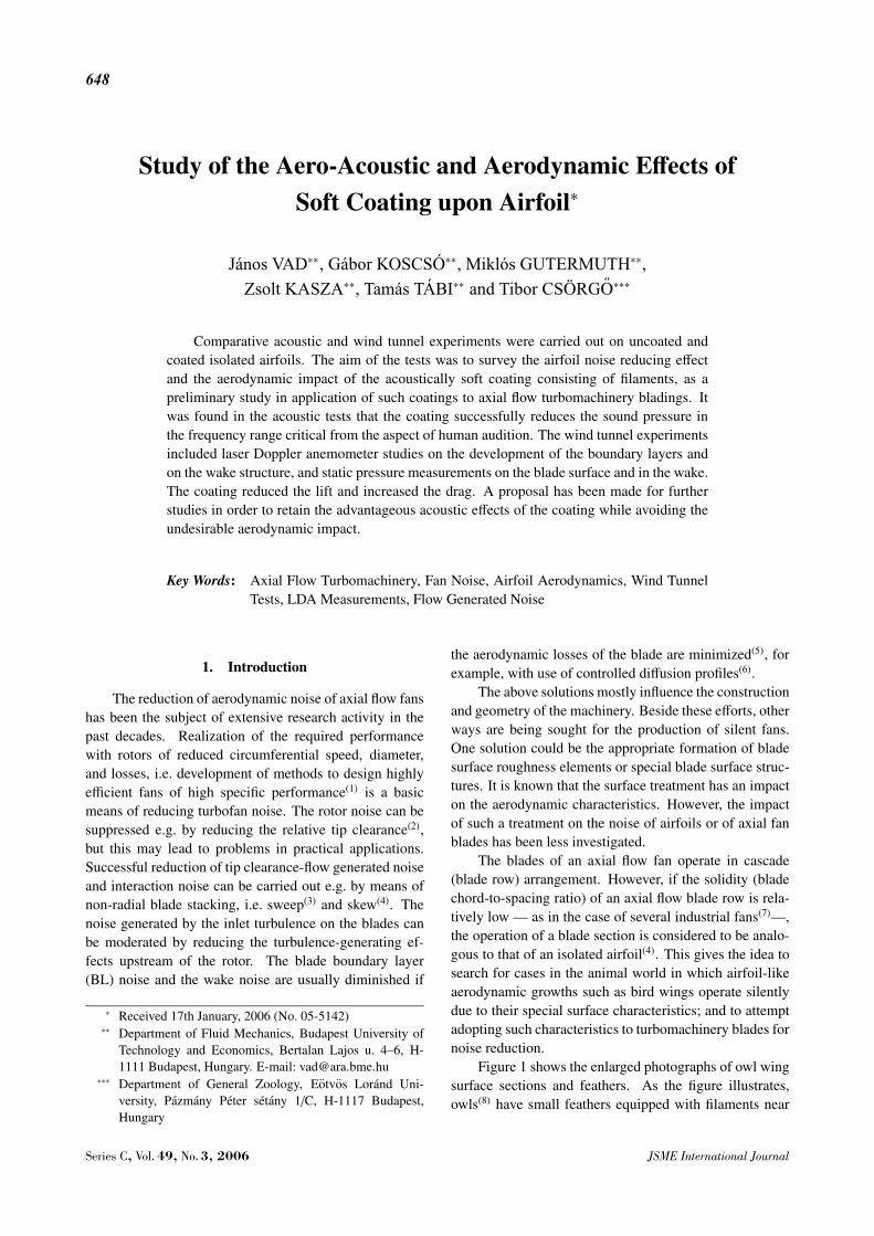
Fig. 10 Development of SS BL at 5 deg incidence. Black dots:uncoated, white dots: coated airfoil
literature-based lift and drag coefficients is supported bythe following comments. As recommended in Ref. (4),the Reynolds number for an axial flow fan blade shouldexceed approximately 150 000 in order to obtain reason-ably good fan efficiency. Above this threshold, only mod-erate efficiency improvement is expected. Since the fanefficiency is closely related to the lift and drag of theblade sections(14), the above yield that only minor changesare expected in cL and cD of a blade section — or of anairfoil being in aerodynamic analogy with the blade sec-tion — above Reynolds number ≈ 150 000. Indeed, asthe data in Ref. (11) show, increase of the Reynolds num-ber of 300 000 by the multiplying factor of 2 causes notmore than 4% and 12% change in cL and cD, respec-tively, regarding the incidences discussed herein. There-fore, authors felt reasonable to consider the data from lit-erature(11) in Table 3 as a basis for brief comparison withthe experiment-based results.
Taking the difference in the Reynolds numbers, therough approximations in numerical integration, and fur-ther approximations (e.g. viewing the present airfoil as a2D one) into consideration, it can be stated that the lift anddrag coefficients computed for the uncoated case studyairfoil are in fair agreement with the data from the liter-ature. This confirms the adequateness of the experimentsreported herein. It is clear that the coating causes unac-ceptable reductions in lift and increases in drag, i.e. drasticreductions also in the lift-to-drag ratio. Such deteriorationis enormous at 15 deg incidence.
The development of the BL along the chord hasbeen mapped via LDA measurements. Figures 10 and11 present the measured SS velocity profiles normalizedby the actual vb values, and the turbulence intensity pro-files, for the two incidences. Only segments of the BLprofiles could be presented (also in Fig. 12), due to thelimited available space in the paper. Extended data setsare available at DFM. The presented quantities and the
Fig. 11 Development of SS BL at 15 deg incidence. Blackdots: uncoated, white dots: coated airfoil
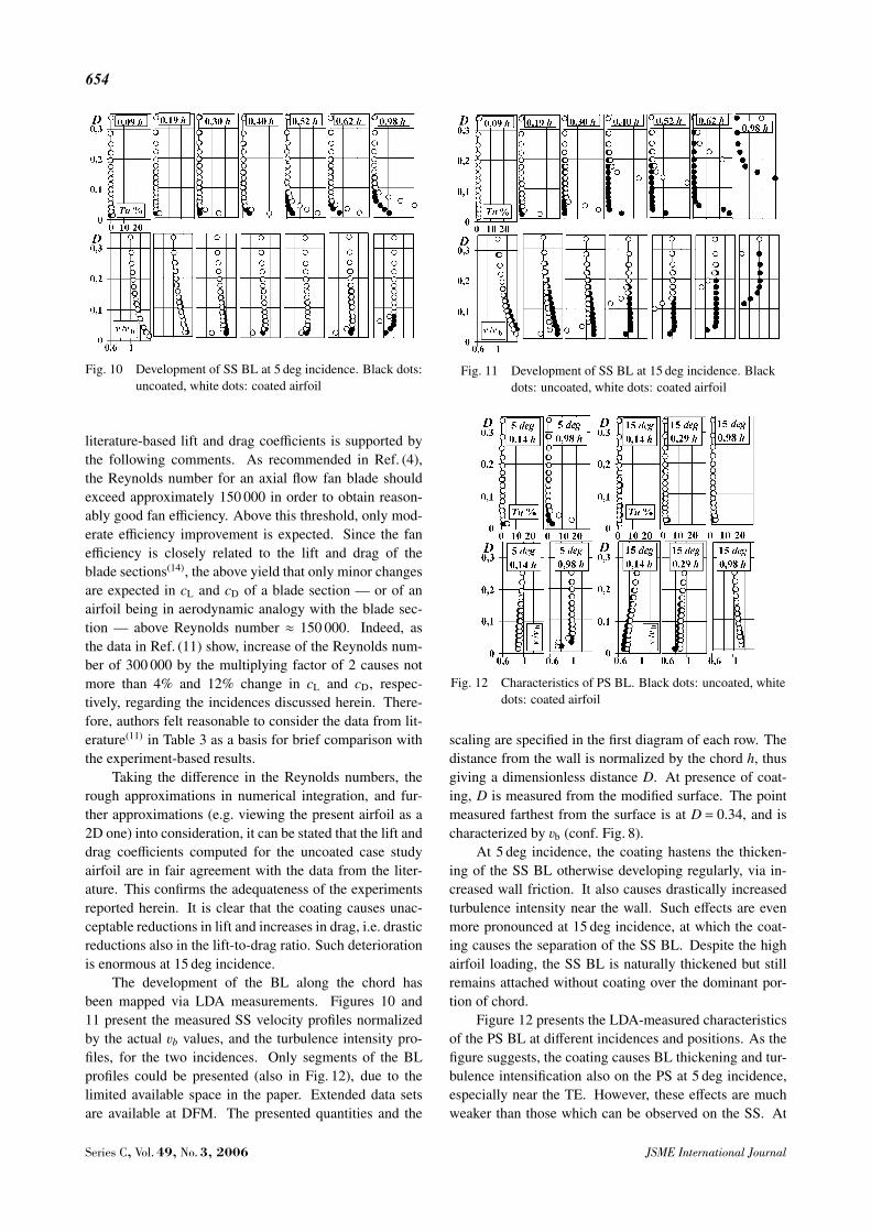
Fig. 12 Characteristics of PS BL. Black dots: uncoated, whitedots: coated airfoil
scaling are specified in the first diagram of each row. Thedistance from the wall is normalized by the chord h, thusgiving a dimensionless distance D. At presence of coat-ing, D is measured from the modified surface. The pointmeasured farthest from the surface is at D = 0.34, and ischaracterized by vb (conf. Fig. 8).
At 5 deg incidence, the coating hastens the thicken-ing of the SS BL otherwise developing regularly, via in-creased wall friction. It also causes drastically increasedturbulence intensity near the wall. Such effects are evenmore pronounced at 15 deg incidence, at which the coat-ing causes the separation of the SS BL. Despite the highairfoil loading, the SS BL is naturally thickened but stillremains attached without coating over the dominant por-tion of chord.
Figure 12 presents the LDA-measured characteristicsof the PS BL at different incidences and positions. As thefigure suggests, the coating causes BL thickening and tur-bulence intensification also on the PS at 5 deg incidence,especially near the TE. However, these effects are muchweaker than those which can be observed on the SS. At
Series C, Vol. 49, No. 3, 2006 JSME International Journal

655
15 deg incidence, it is especially conspicuous that the coat-ing obstructs the pressure surface contour of the airfoil inflow deceleration — and thus, it inhibits the developmentof overpressure — near the LE, i.e. the velocity near thesurface is lower without than with coating (conf. Fig. 8).
5. Combination of Acoustic and Aerodynamic As-pects: Further Research Steps
The coating under present investigation widened thewake and increased the turbulence level over the entireblade surface and in the wake. In a classic sense, one mayexpect that such effects would increase the BL noise andthe wake noise. However, the acoustic studies suggestedjust the opposite tendency. The noise reduction can beexplained on the basis of the following assumptions, ne-cessitating further research steps:
1 ) The noise generated by the inlet turbulence mayhave possibly been reduced by the application of acous-tically soft coating near the LE of the airfoil. This is inaccordance with the fact that owls have velvet-like feath-ers only near the LE of their wing. If the entire wing werecovered by such feathers, the owl could quite possibly op-erate only with reduced performance and increased losses.Birds live in the near-ground region of the atmosphere.The lowest 100 m layer is characterized by a mean ve-locity in the order of magnitude of some m/s, and witha turbulence intensity which might even be exceeding 20percent(15), (16). In natural environments with vegetation,turbulent vortices in the order of magnitude smaller thanthe size of an owl wing are characteristic. Therefore, theinlet turbulence may be a significant cause of noise.
2 ) The noise caused by turbulent fluctuations in theBL may have been reduced. Although the coating in-creased the turbulence intensity in the BL, its noise-reducing function dominated over the noise-generation ef-fect of increased turbulence. This feature of the coating isto be examined at different turbulence levels. The powerspectra of turbulence may play an important role in thisnoise reduction mechanism. Therefore, detailed turbu-lence measurements, by means of hot-wire anemometry,over the airfoil surface and in the wake are to be carriedout.
3 ) Although the turbulence intensity level in thewake was increased due to the coating, its spectral dis-tribution may have been modified in such a way that therelated wake noise, in terms of the A-weighted sound pres-sure level, has been reduced. Figure 5 suggests that thereduction of sound pressure at higher frequencies is at thecost of increase of noise at middle frequencies. This as-sumption also necessitates hot-wire anemometer measure-ments over the blade surface and in the wake, in order toexamine the correlation between sound pressure and tur-bulence spectra. Computational aero-acoustics with in-volvement of Large Eddy Simulation(17) also support such
investigations.The further research plan involves the following as-
pects.1 ) The acoustically soft fibrous coating is to be cov-
ered by plastic foil of thickness in the order of magnitudeof 0.01 mm. Such “cover” provides aerodynamically ben-eficial smooth airfoil surface, thus eliminating the aerody-namic demerits reported herein. In addition, it is acous-tically transparent and thus, it enables retaining the noisereducing effect of the fibrous coating.
2 ) In order to distinguish between the major effectsof inlet turbulence as well as turbulent fluctuations in theBL from the viewpoint of noise generation and suppres-sion, the fibrous coating equipped with the above men-tioned plastic cover is to be restricted to the followingzones of the airfoil surface, in consecutive research steps:i) the near-LE region, ii) accelerating flow region on theSS, iii) decelerating flow region on the SS, iv) the PS, v)combinations of the above.
3 ) Airfoils of porous or/and visco-elastic materialsare also to be tested.
4 ) The tests are to be carried out with various coatingtypes and inlet turbulence levels.
6. Summary
An experimental investigation was carried out on anisolated rectilinear airfoil in order to survey the acousticand aerodynamic effects of an acoustically soft coatingconsisting of filaments (velvet), covering the entire airfoilsurface, at incidences of 0 deg, of maximum lift-to-dragratio and of maximum lift of the uncoated airfoil. The re-sults are summarized as follows:
1 ) The coating was found to reduce the A-weightedsound pressure level of noise generated by the airfoil ateach incidence. The coating reduced the sound pressurelevel in the frequency range critical from the viewpoint ofhuman audition, and increased it at lower and higher fre-quencies less significant from the aspect of A-weighting.
2 ) The coating increased the wall friction. This re-sulted in unfavorable aerodynamic effects, manifestingthemselves for the most part on the suction side. The ac-celeration and the related depression have been moderatedon the suction surface. The suction side boundary layerand consequently, the wake, have been thickened. The tur-bulence has been intensified in the boundary layer and inthe wake. Such phenomena were more pronounced at highincidence, at which the coating caused even the separationof the suction side boundary layer, remaining still attachedwithout coating. These effects led to unacceptably strongreduction in lift and increase in drag, being very drastic athigh incidence.
3 ) To retain the beneficial acoustic effects but toavoid the unfavorable aerodynamic impact, further studiesare necessary. This should involve coating combined with
JSME International Journal Series C, Vol. 49, No. 3, 2006

656
acoustically transparent plastic foil layer, various coatingmaterials and configurations restricted to only a part of theairfoil surface, and various inlet turbulence levels. Air-foils of porous or/and visco-elastic materials are also to betested.
4 ) For a better understanding of noise reductionmechanisms due to coating, the former experiments shallbe supplemented with turbulence spectra measurementsover the blade surface and in the wake.
Acknowledgment
This work has been supported by the Hungarian Na-tional Fund for Science and Research under contractsNo. OTKA T 043493, K63704 and T 037651, and, on thebehalf of J. Vad, out of the Istvan Szechenyi Fellowshipunder contract No. SZO 271/2003.
References
( 1 ) Vad, J. and Corsini, A., Comparative Investigation onAxial Flow Industrial Fans of High Specific Perfor-mance with Unswept and Forward Swept Blades at De-sign and Off-Design Conditions, Proc. 9th InternationalSymposium Transport Phenomena Dynamics Rotat-ing Machinery, Honolulu, Hawaii, USA, Log. No.FD-ABS-016, CD-ROM, (2002).
( 2 ) Marcinowski, H., Der Einfluss des Laufradspaltesbei Leitrad Losen, frei Ausblasenden Axialventilator,Voith Forschung und Konstruktion, No.3 (1958).
( 3 ) Wright, T. and Simmons, W.E., Blade Sweep for Low-Speed Axial Fans, ASME J. Turbomachinery, Vol.112(1991), pp.151–158.
( 4 ) Carolus, T., Ventilatoren, (2003), Teubner Verlag.( 5 ) Daly, B.B., Fan Noise Measurement I - II. Heating Air
Cond. Vent. Inst. (London), No.12, p.414 (1962), No.1,p.14 (1963).
( 6 ) Sanger, N.L. and Shreeve, R.P., Comparison of theCalculated and Experimental Cascade Performancefor Controlled-Diffusion Compressor Stator Blading,ASME J. Turbomachinery, Vol.108 (1986), pp.42–50.
( 7 ) HELIOS Hauptkatalog 2001/2002. Druckschrift-Nr. 95178.005 / 03.01
( 8 ) Videler, J.J., Avian Flight, (2005), Oxford UniversityPress.
( 9 ) Cramp, S. and Brooks, D.J., Handbook of the Birds ofEurope, the Middle East and North Africa, (1992), Ox-ford University Press.
(10) Csorgo, T., Private communication, (2005).(11) Patterson, G.N., Ducted Fans: Design for High Effi-
ciency, Australian Council for Aeronautics, Rep. ACA7, (1944).
(12) Corsini, A. and Rispoli, F., The Role of Forward Sweepin Subsonic Axial Fan Rotor Aerodynamics at De-sign and off-Design Operating Conditions, ASME Pa-per GT2003-38671, (2003).
(13) Vad, J., Effects of Sweep and Spanwise Changing Cir-culation Applied to Airfoils: A Case Study, J. Com-putational and Applied Mechanics, Vol.5, No.2 (2004),pp.383–400.
(14) Vad, J., Kwedikha, A.R.A. and Jaberg, H., Influence ofBlade Sweep on the Energetic Behavior of Axial FlowTurbomachinery Rotors at Design Flow Rate, ASMEPaper GT2004-53544, (2004).
(15) VDI 3738 Part 12, Environmental Meteorology, Phys-ical Modeling of Flow and Dispersion Processes inthe Atmospheric Boundary Layer, Application of WindTunnels, (2000).
(16) Goricsan, I., Balczo, M., Regert, T. and Suda, J.M.,Comparison of Wind Tunnel Measurement and Nu-merical Simulation of Dispersion of Pollutants in Ur-ban Environment, Impact of Wind and Storm on CityLife and Built Environment, Edited by van Beeck,J.P.A.J., COST C14 International Conference on Ur-ban Wind Engineering and Buildings Aerodynamics,(2004), pp.D.6.1–D.6.10.
(17) Lohasz, M.M., Rambaud, P. and Benocci, C., FlowFeatures in a Fully Developed Ribbed Duct Flow asa Result of LES, ERCOFTAC International Sympo-sium on Engineering Turbulence Modeling and Mea-surements (ETMM6), Sardinia, Italy, (2005), pp.267–276.
Series C, Vol. 49, No. 3, 2006 JSME International Journal