Embed Size (px)
Citation preview
i
STUDY OF THE BEHAVIOUR OF BAMBOO
REINFORCED CONCRETE BEAMS
A Thesis
by
MD. AHSAN SABBIR
MASTER OF SCIENCE IN CIVIL ENGNEERING (STRUCTURAL)
DEPARTMENT OF CIVIL ENGINEERING
BANGLADESH UNIVERSITY OF ENGINEERING AND TECHNOLOGY
DHAKA
March, 2011
ii
STUDY OF THE BEHAVIOUR OF BAMBOO REINFORCED CONCRETE BEAMS
A Thesis
by
Md. Ahsan Sabbir
Submitted to the Department of Civil Engineering, Bangladesh University of Engineering
and Technology (BUET), Dhaka in partial fulfillment of the requirements for the degree
of
MASTER OF SCIENCE IN CIVIL ENGNEERING (STRUCTURAL)
March, 2011
BANGLADESH UNIVERSITY OF ENGINEERING AND TECHNOLOGY
DHAKA
iii
This thesis titled “STUDY OF THE BEHAVIOUR OF BAMBOO REINFORCED CONCRETE
BEAMS”, submitted by MD. AHSAN SABBIR, Roll No. 100704305F, Session: October 2007,
has been accepted as satisfactory in partial fulfillment of the requirement for the degree of
Master of Science in Civil Engineering (Structural) on 6th March, 2011.
BOARD OF EXAMINERS
Dr. Sk. Sekender Ali : Chairman Professor (Supervisor) Department of Civil Engineering, BUET _______________________ Dr. Md. Zoynul Abedin : Member Professor and Head Department of Civil Engineering, BUET ______________________ Dr. Ahsanul Kabir : Member Professor Department of Civil Engineering, BUET
_______________________ Dr. Khan Mahmud Amanat : Member Professor Department of Civil Engineering, BUET
_______________________ Dr. Md. Monjur Hossain : Member Professor (External) Department of Civil Engineering, KUET
iv
CANDIDATE’S DECLARATION
It is hereby declared that this project or any of it has not been submitted elsewhere for the award of any degree or diploma.
(Md. Ahsan Sabbir)
v
DEDICATION
This Thesis is Dedicated to My Late Father
vi
ACKNOWLEDGEMENTS
Praise be to Almighty Allah. The author expresses his utmost gratitude to Allah(SWT) for all his
accomplishments.
The author would like to thank his supervisor Dr. Sk. Sekender Ali, Professor, Department of
Civil Engineering, Bangladesh University of Engineering and Technology (BUET) for giving
this interesting topic. The idea of this project was initially conceived by him. The author
appreciates very much his enthusiastic and enthusing support. He encouraged playful and
independent thinking and gave the freedom to try out new ways. With his very positive approach
he assisted in boiling the essential out of results and helped to make the work converge to a
thesis. The author regards him as an outstandingly good scientific supervisor and a very nice
person to work with.
The author is undoubtedly grateful to his family members and his friends for their co-operation.
vii
ABSTRACT
An experimental study has been made to explore the possibility of using bamboo and
bamboo twig as a potential reinforcement in concrete beams. To achieve this objective, a
series of tension tests were conducted to derive the stress-strain characteristics of bamboo along
with a number of pullout tests to evaluate bond strength followed by bending test of beam to
determine the ultimate load carrying capacity of concrete beams reinforced with bamboo and
bamboo twig. Finally, the test results were compared with similar steel reinforced concrete
beams.
For tension test, two types of reinforcements were tested, bamboo and bamboo twig. First three
samples of finished bamboo and bamboo twig were tested in natural condition (without
treatment). Then five samples of finished bamboo and bamboo twig were tested with GI wire
spiral at the ends for improved gripping. From these tests, the tensile strength, proof strength and
modulus of elasticity were determined from stress-strain curve for both bamboo and bamboo
twig.
Nine pull out tests were performed for both bamboo and bamboo twig specimen. In these pullout
tests, three samples were in natural condition, three samples were coated with tar for water
proofing and three samples were coated with tar along with pierced nails at the ends. From this
test, bond strength of bamboo and bamboo twig was determined.
Four beams with same cross section were constructed and tested under two point loading. The
main parameters considered are the reinforcement type and the reinforcement ratio. To improve
the bond strength, pierced nails were used at both ends of bamboo and bamboo twig
reinforcement. Two types of shear reinforcements (bamboo and bamboo twig) were used. The
beams were tested after fifty days and concrete compressive strength was determined from
cylinder test on the same day. During testing, two dial gages were installed to measure the
deflection. From bending tests, cracking load, ultimate failure load and failure patterns were
obtained. Finally, the ultimate failure loads were compared with the corresponding failure load
of steel reinforced concrete beam.
viii
From these tests, satisfactory results are obtained in terms of tensile strength, bond strength,
stress-strain characteristics of bamboo and bamboo twigs and flexural behaviour of bamboo
reinforced concrete beams.
ix
TABLE OF CONTENT
Page No.
DEDICATION v
ACKNOWLEDGEMENT vi
ABSTRACT vii
TABLE OF CONTENT ix
LIST OF SYMBOLS
xiii
CHAPTER 1 INTRODUCTION
1.1 General 1
1.2 Methodology 1
1.3 Objective of the research 2
1.4 Scope of the work 3
CHAPTER 2 LITERATURE REVIEW
2.1 Introduction 4
2.2 Characteristics of Bamboo and Bamboo Twig 4
2.3 Bamboo and Bamboo Twig as a Construction Material: 6
2.4 Applications of Bamboo and Twig 9
2.5 Comparison of Bamboo and Bamboo Twig with Steel 9
2.6 Earlier Studies 10
CHAPTER 3 EXPERIMENTAL PROGRAM
3.1 Introduction 14
3.2 Sample Preparation 14
3.2.1 Preparation Bamboo Specimen 14
3.3.2 Preparation of Bamboo Twig Specimen 15
3.3 Tension Test 15
x
3.3.1 Gripping of Bamboo Reinforcement 16
3.3.2 Preparation of Specimens 18
3.3.3 Test Setup 19
3.4 Pullout Test 19
3.4.1 Preparation of Specimen 21
3.5 Bending Test of Beam 26
3.5.1 Selection of Geometric Properties of Beam 26
3.5.2 Variables Considered for Bending Test 29
3.6 Preparation of Beams 30
3.6.1 Preparation of Bamboo Reinforced Beam (1.5% Reinforcement) 30
3.6.2 Preparation of Bamboo Reinforced Beam (2.5% Reinforcement) 34
3.6.3 Construction of Bamboo Twig Reinforced Beam (1.5%
reinforcement)
37
3.6.4 Construction of Bamboo Twig Reinforced Beam (2.5%
Reinforcement)
41
3.7 Preparation of Formwork and Placement of Bamboo Reinforcement 44
3.8 Concrete Mix Design, Casting and Compression Tests 45
3.9 Test Set-Up, Instrumentation and Data Acquisition 47
CHAPTER 4 RESULTS OF EXPERIMENTS
4.1 Introduction 51
4.2 Results of Tension Test for Bamboo Specimen 51
4.2.1 Results of Tension Tests for Bamboo Specimens (Normal bamboo
surface at grip area)
51
4.2.2 Results of Tension Tests for Bamboo Specimens (Bamboo surface
with GI wire at grip area)
51
xi
4.2.3 Stress Strain Relation 53
4.3 Results of Tension Test for Bamboo Twig Specimen 58
4.3.1 Results of Tension Tests for Bamboo Specimens (Normal bamboo
surface at grip area)
58
4.3.2 Results of Tension Tests for Bamboo Twig Specimens (Bamboo
surface with GI wire at grip area)
60
4.3.3 Stress Strain Relation 61
4.4 Pullout Test 63
4.4.1 Results of Pullout Test for Bamboo Specimen 64
4.4.2 Results Pullout Test for Bamboo Twig Specimen 68
4.5 Results of Beam Tests 72
4.5.1 Beam with 1.5% Bamboo Reinforcement 72
4.5.2 Beam with 2.5% Bamboo Reinforcement 75
4.5.3 Beam with 1.5% Bamboo Twig Reinforcement 78
4.5.4 Beam with 2.5% Bamboo Twig Reinforcement 81
4.5.5 Compression Test of Concrete Cylinder 84
4.5.6 Comparison of Results between the Bamboo and Bamboo Twig
Reinforcement
84
4.5.7 Comparison of ultimate loads for bamboo, bamboo twig and steel
reinforced concrete beams
89
4.5.8 Investigation of post failure 91
xii
CHAPTER 5 CONCLUSION AND RECOMMENDATION 5.1 Tension Tests 95
5.2 Pullout Tests 96
5.3 Bending Test with Two Point Loading 96
5.3 Recommendation for Further Study 97
REFERENCES 99
APPENDIX-A 101
APPENDIX-B 116
xiii
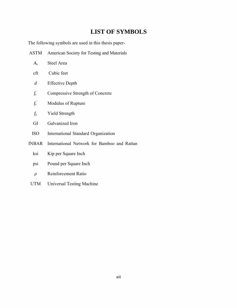
LIST OF SYMBOLS
The following symbols are used in this thesis paper-
ASTM American Society for Testing and Materials
As Steel Area
cft Cubic feet
d Effective Depth
fc' Compressive Strength of Concrete
fr' Modulus of Rupture
fy Yield Strength
GI Galvanized Iron
ISO International Standard Organization
INBAR International Network for Bamboo and Rattan
ksi Kip per Square Inch
psi Pound per Square Inch
ρ Reinforcement Ratio
UTM Universal Testing Machine
1
CHAPTER 1
INTRODUCTION
1.1 General
Traditionally, most buildings are built using materials such as timber, reinforced concrete and
structural steel. Specifically, concrete is a high quality and economical material with its ability to
support fire and earthquake defense in buildings constructed in developed as well as developing
countries. Good concrete is easy to make but without some sort of reinforcement it lacks tensile
strength. Concrete by itself can’t make a beam or span a distance. Beams want to deflect under
load which causes the bottom of a beam to stretch. Concrete doesn’t stretch - instead it cracks.
One of the significant limitations of concrete is its low tensile strength. Steel reinforcing bars are
typically used as reinforcement. Steel is one of the best materials for complementing the low
tensile strength of concrete because of its high tensile strength. Even though steel reinforcement
is a very suitable material for complementing concrete’s low tensile strength, there are many
difficulties such as economics, technique, and efficiency that need to be addressed. On the other
hand some parts of the world people build their houses by using only concrete or mud-brick
which is very dangerous. To overcome these problems, many scientists and engineers have been
trying to seek out new materials for improving the tensile capacity of concrete. In this case,
bamboo and bamboo twig may be the alternative materials to substitute the reinforcing bar in
concrete for less important structures.
1.2 Methodology
This experimental study will be completed in three different steps which are mentioned below.
i. Tension test of both bamboo and bamboo twig will be done for natural and prepared grip
condition. From these results stress-strain curves will be developed and yield strength
will be calculated by following the standard procedure (ASTM E6).
2
ii. In the second phase the bond strength will be determined for both bamboo and bamboo
twig with three different conditions (natural, protective coating and pierced nail with
protective coating).
iii. Last of all two beams of bamboo reinforcement and two beams of bamboo twig
reinforcement will be constructed and tested. Finally, these test results will be compared
with corresponding steel reinforced beams.
1.3 Objectives of the Research
Whereas the mechanical properties and behavior of steel reinforced concrete have been
thoroughly studied and well documented, there exists no comprehensive data describing bamboo
and bamboo twig reinforced concrete. Therefore, the aim of this study is to provide a preliminary
contribution toward the collection of the mechanical properties and behaviors of bamboo and
bamboo twig reinforced beams. The objectives of the investigation are summarized below:
a) To investigate the behavior of bamboo and bamboo twigs under tension and hence to
determine the tensile strength, the stress-strain relationship and the modulus of elasticity
from tension test.
b) To determine the bond strength between bamboo and surrounding concrete.
c) Similar investigation will be made for bamboo twig.
d) To determine the cracking and ultimate strength of bamboo and bamboo twig reinforced
concrete beam.
e) The cracking and the ultimate failure pattern of bamboo and bamboo twig reinforced
concrete beam.
f) Compare all the findings of bamboo and bamboo twig as reinforcement in concrete with
steel reinforcement.
g) Based on the test results justify the use of bamboo and bamboo twig as reinforcement for
concrete for low cost housing.
3
1.4 Scope of the Work
The outcome of this study may be helpful in deciding whether bamboo and bamboo twig can be
used as reinforcement in the concrete. The tension test of bamboo and bamboo twig will be
helpful to understand the tensile behavior of such natural material. Pull out can be used to
determine the bond strength of bamboo and bamboo twig. If the cracking pattern and ultimate
load test of beam shows a satisfactory performance, it can be a great finding for low cost
housing.
4
CHAPTER 2
LITERATURE REVIEW
2.1 Introduction
This chapter presents a literature review spanning the range of the complex biology of
bamboo for understanding the mechanical behavior and different applications of the bamboo.
Since no previous study on bamboo twig has been made before, only the bamboo related studies
will be mentioned.
2.2 Characteristics of Bamboo and Bamboo Twig
Bamboo is primarily a type of giant grass with woody stems. The stems are called “shoots” when
the plant is young and “culms” when the plant is mature. Each bamboo plant consists of two
parts – the “culm”/stem that grows above the ground and the underground “rhizome” that bears
the roots of the plant. Bamboo grows in either clumps or like runners. Bamboo growing in a
clump adds a new shoot around one central culm thereby increasing the clump size radially. As
for runners, they just literally “run” around, growing in a haphazard manner. “A single bamboo
clump can produce up to 15 kilometers of usable pole (up to 30 cm in diameter) in its lifetime.”
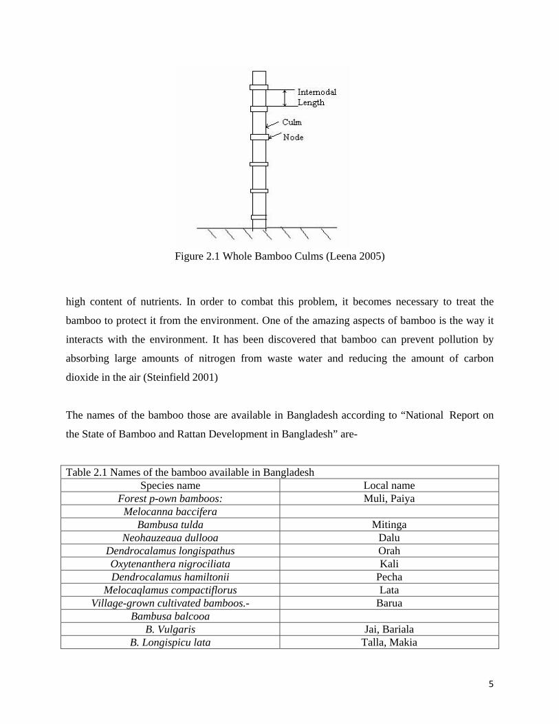
Bamboo culms (Figure 1.1) are a cylindrical shell divided by solid transversal diaphragms at
nodes and have some intriguing properties such as high strength in the direction parallel to the
fibers, which run longitudinally along the length of the culm, and low strength in a direction
perpendicular to the fibers. The density of fibers in cross-section of a bamboo shell varies with
thickness as well as height. Fiber distribution is more uniform at the base than at the top or the
middle.
The mechanical properties vary with height and age of the bamboo culm. Research findings
indicate that the strength of bamboo increases with age. The optimum strength value occurs
between 2.5 and 4 years. The strength decreases at a later age (Amanda and Untao 2001). The
function of the nodes is to prevent buckling and they play a role of axial crack arresters.
One major problem with bamboo is that it is a living organism which is subject to fungi and
insect attacks. Bamboo is more prone to insect attack than other trees and grasses because of its
5
Figure 2.1 Whole Bamboo Culms (Leena 2005)
high content of nutrients. In order to combat this problem, it becomes necessary to treat the
bamboo to protect it from the environment. One of the amazing aspects of bamboo is the way it
interacts with the environment. It has been discovered that bamboo can prevent pollution by
absorbing large amounts of nitrogen from waste water and reducing the amount of carbon
dioxide in the air (Steinfield 2001)
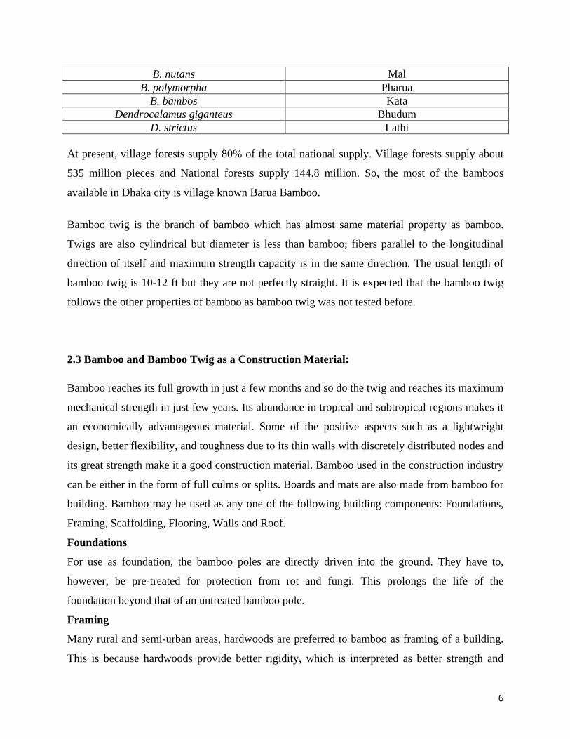
The names of the bamboo those are available in Bangladesh according to “National Report on
the State of Bamboo and Rattan Development in Bangladesh” are-
Table 2.1 Names of the bamboo available in Bangladesh Species name Local name
Forest p-own bamboos: Muli, Paiya Melocanna baccifera
Bambusa tulda Mitinga Neohauzeaua dullooa Dalu
Dendrocalamus longispathus Orah Oxytenanthera nigrociliata Kali Dendrocalamus hamiltonii Pecha
Melocaqlamus compactiflorus Lata Village-grown cultivated bamboos.- Barua
Bambusa balcooa B. Vulgaris Jai, Bariala
B. Longispicu lata Talla, Makia
6
B. nutans Mal B. polymorpha Pharua
B. bambos Kata Dendrocalamus giganteus Bhudum
D. strictus Lathi At present, village forests supply 80% of the total national supply. Village forests supply about
535 million pieces and National forests supply 144.8 million. So, the most of the bamboos
available in Dhaka city is village known Barua Bamboo.
Bamboo twig is the branch of bamboo which has almost same material property as bamboo.
Twigs are also cylindrical but diameter is less than bamboo; fibers parallel to the longitudinal
direction of itself and maximum strength capacity is in the same direction. The usual length of
bamboo twig is 10-12 ft but they are not perfectly straight. It is expected that the bamboo twig
follows the other properties of bamboo as bamboo twig was not tested before.
2.3 Bamboo and Bamboo Twig as a Construction Material:
Bamboo reaches its full growth in just a few months and so do the twig and reaches its maximum
mechanical strength in just few years. Its abundance in tropical and subtropical regions makes it
an economically advantageous material. Some of the positive aspects such as a lightweight
design, better flexibility, and toughness due to its thin walls with discretely distributed nodes and
its great strength make it a good construction material. Bamboo used in the construction industry
can be either in the form of full culms or splits. Boards and mats are also made from bamboo for
building. Bamboo may be used as any one of the following building components: Foundations,
Framing, Scaffolding, Flooring, Walls and Roof.
Foundations
For use as foundation, the bamboo poles are directly driven into the ground. They have to,
however, be pre-treated for protection from rot and fungi. This prolongs the life of the
foundation beyond that of an untreated bamboo pole.
Framing
Many rural and semi-urban areas, hardwoods are preferred to bamboo as framing of a building.
This is because hardwoods provide better rigidity, which is interpreted as better strength and
7
most hardwoods are better resistant to rot and fungi than untreated bamboo. There is also a
certain amount of prestige associated with using hardwoods as they are more expensive and
hence a potential symbol of wealth. However, in earthquake prone areas, bamboo is given higher
preference because of higher resilience.
Scaffolding
Since ancient times, bamboo poles have been tied together and used as scaffolding. The
properties of bamboo such as resilience, shape and strength make it an ideal material for the
purpose. The working platforms for masons can also be built of bamboo.
Flooring
Earlier most houses had a floor of rammed earth raised above the ground a little with filling to
prevent flooding due to drainage. Later houses had raised floors. This was more hygienic and
had a serviceable area underneath that could be put to good use. Bamboo was used for this
purpose. The higher resilience of bamboo culms made them better than conventional timber for
floor beams. These would then be covered by either small whole culms, strips or bamboo boards
made by opening and flattening out culms attached to the beams by wire lashings or small nails.
Walls
There are several ways in which bamboo can be used in wall-building. They are:
Bajareque wall
This wall-building technique is very well-known in Latin America. Bamboo strips or slender
culms are nailed or tied on either side of timber, or in some cases bamboo, posts. The
intermediate space is then filled with mortar or mortar and stone.
Bamboo Board wall
This is a common method of construction in Indonesia. Horizontal bamboo poles are nailed/tied
to the mortices in vertical supporting bamboo poles. The bamboo board panels are then nailed to
the horizontals. These walls maybe finished with stucco. For better adhesion, barbed wire
reinforcing is used under the stucco.
Wattle wall
These walls consist primarily of bamboo or reed lath used as a base for application of a mud
plaster to one or both sides. A mixture of clay and organic fiber is used as plaster.
8
Mat wall
Mat walls are constructed by nailing a thin bamboo mat to either sides of a braced timber frame.
These walls may then be plastered with cow dung, mud, sand or lime.
Solid wall
This wall uses full or split sections of bamboo side by side vertically in a frame. The wall may be
made water-tight by cladding with closely woven mats.
Roof
Bamboo is used commonly as both framing and roofing. The following are the most common
type of bamboo roofing:
Bamboo tile roofing
This is the simplest form of bamboo roofing. The culms are split into halves, the diaphragms
scooped out and these run full length from eave to ridge. The first layer of bamboo splits are laid
concave side up and the second layer interlocks over the first with convex side up. Though a very
simple method, it can be completely watertight. The minimum pitch of the roof should be 30 °.
Thatch roofing
The roof is framed using bamboo purlins and rafters. The thatch is tied to this framing. Split
bamboo is used to pin down the thatch at valleys and ridges.
Trusses
For the spanning larger distances in public utility buildings like schools, storage areas,
commercial buildings, bamboo is utilized as a truss member. Bamboo has a high strength/weight
ratio and hence is a good alternative for roof framing. An award-wining example of bamboo
being used in modern day construction is the pavilion designed by Simon Velez, architect-artist-
engineer in Manizales, Colombia. It was an exact replica of the EXPO2002 pavilion designed by
him in Hannover, Germany. He designed the pavilion with bamboo to take 7 feet plus of
overhangs. He filled the joints with concrete to increase the traction strength of bamboo making
it stronger than steel. He married organic and inorganic materials for a second time when he used
bamboo fiber reinforced cement board for the roofing. The bamboo was protected from insects
and pests by an age-old Japanese technique of “smoking bamboo”.
Bamboo twig is generally not used in construction work but it is more flexible than bamboo
itself. In this study the feasibility of bamboo twig will be evaluated for the very first time in the
field of construction work.
9
2.4 Applications of Bamboo and Twig
Bamboo and its twig are being used in a wide variety of applications such as recreation, defense,
housing and construction. In regards to recreation bamboo twig has been used to construct a
variety of musical instruments. In addition to the fact that bamboo twig can be used in the arts.
One of the major applications of bamboo and twig are for construction and housing. It is
estimated that one billion people live in bamboo houses. It can also be used to make furniture.
Bamboo and Bamboo twig can be fashioned into many shapes leading to artistic freedom as they
have been crafted into furniture, decorative items such as home decoration, dishware, dolls, toys,
jewelry and more.
One of the most popular applications of bamboo is in the manufacture of umbrellas which
have a simple design with 38 bars. Specifically, umbrellas in European are curved extremely
with a textile covering in individual triangular sections. The culm has the ability of
maintaining considerable tensile forces transverse to the bars so enabling the bars to be bent
considerably when the umbrella is open.
Bamboo twig is also a popular tool for acquiring food: as its fishing rods has been used to catch
fish for long time. In earlier times, bamboo twig could be used as a blunt weapon, or it could be
sharpened to provide food or defense. It would also make a decent shaft for a spear.
2.5 Comparison of Bamboo and Bamboo Twig with Steel
One of the properties that would make bamboo and bamboo twig a good substitute to steel in
reinforced concrete is its strength. The strength of bamboo and bamboo twig is greater than many
timber products which are advantageous, but it is quite less than the tensile strength of steel.
Bamboo and Bamboo twig are easily accessible as it is available in almost every tropical and
subtropical regions, this lowers the cost of construction and increases the strength of the
buildings that would otherwise be unreinforced. One major problem with bamboo and bamboo
twig is that it attracts living organism such as fungi and insects. Bamboo twig is more prone to
insects than other trees and grasses because they have a high content of nutrients. In order to
combat this problem, it is necessary to treat bamboo and bamboo twig to protect it from the
environment. Steel does not have this problem but it also needs to be coated in order to protect it
10
from rusting. Bamboo twig is very light in weight compared to steel. Due to its low modulus of
elasticity, bamboo and bamboo twig can crack and deflect more than steel reinforcement under
the same conditions. These aspects put bamboo and bamboo twig on the list of viable
construction materials. These properties, when combined, suggest that bamboo and bamboo twig
will make a fine addition to the current selection of materials but it is necessary that people in
general be made more familiar with their strengths and weaknesses.
2.6 Earlier Studies
This chapter presents a literature review spanning the range of the complex biology of
Bamboo for understanding to prior research conducted on mechanical behavior and
different applications of the Bamboo. Since no previous study on bamboo twig has been made
before, only the bamboo related studies will be mentioned.
Ghavami (1995) discussed the mechanical properties of bamboo, specifically pertaining to
bamboo in concrete. This study showed that the ultimate strength of a concrete beam reinforced
with bamboo is approximately 4 times when compared with un-reinforced concrete. It was
found that, compared to steel, the bond between bamboo and concrete is considerably poor and
the bamboo has a Modulus of Elasticity of one fifteenth compared to steel. Bamboo’s
compressive strength is much lower than its tensile strength, and the strength is higher along the
fibers and lower transverse to the fibers.
Ghavami (2004) studied the mechanical properties of six different types of bamboo, proper
treatments that should be applied to bamboo, and the methods that should be employed
when utilizing bamboo as concrete reinforcement. The positive attributes of bamboo are listed,
supporting its environment-friendly nature. Some negative attributes of bamboo were also
given, focusing on its tendency to absorb water. The properties of bamboo were found to be
based upon a functionally graded construction, with its most important property being that its
ratio of strength to specific weight is six times greater than steel. Test results showed the
ideal value for the percentage of bamboo in concrete to be 3% of the cross-sectional area of
concrete, allowing for the highest applied load, and the necessity for drying and water
repellant treatments. This study concluded that bamboo can substitute steel satisfactorily, and
11
that there is a need to establish the characteristic strength of bamboo for design
purposes.
The United States Naval Civil Engineering Laboratory (1966, 2000) reported a study providing
a set of instructions on how to properly construct a variety of structures and structural elements
using bamboo. This study suggested not to use green, unseasoned bamboo for general
construction, nor to use un-waterproofed bamboo in concrete. Concerning bamboo reinforced
concrete, it was found that the concrete mix designs may be the same as that used with steel,
with a slump as low as workability will allow. It was recommended that the amount of bamboo
reinforcement in concrete be 3-4% of the concrete’s cross-sectional area as the optimum amount. It
concludes that bamboo reinforced concrete is a potential alternative light construction method at
a low cost.
Lo et al. (2004) gave a detailed description of the mechanical properties of bamboo in their
study. They found that the physical, as well as mechanical attributes vary with respect to
diameter, length, age, type, position along culms, and moisture content of bamboo.
Masani (1977) conducted an in-depth study outlining the proper ways to utilize bamboo in
construction. A listing of the positive aspects of bamboo is given, citing examples pertaining
to its economical, mechanical, and environmental properties. When used as reinforcement in
concrete, directions are given to insure a better performance, including discussions on
waterproofing, pressure-treating, concrete design, and beam design. This study found that the
Bamboo reinforcement area should be 5 times the typical steel reinforcement area, and that
even when fine cracks develop on the surface of Bamboo, the load carrying capacity of the
member is not reduced. The only negative properties of bamboo given are its susceptibility to
attack by insects, fungi and dried bamboo is prone to catch fire.
Amada et al. (1997) investigated the mechanical and physical properties of bamboo. They
conducted a thorough investigation into the structure and purposes of the nodes, which they
found to strengthen the bamboo culm. They also commented on the advantage bamboo has
over other natural building materials with its fast growth rate.
12
Amada and Untao (2001) studied the fracture properties of bamboo. In contradiction
to other studies, this study states that the tensile strength of bamboo fibers almost corresponds
to that of steel. The main discovery is that the fracture properties of bamboo depend upon the
origin of fracture. In the nodes, it is found that the average fracture toughness is lower than
the minimum value of the entire culm, suggesting that the fibers in the nodes do not contribute
any fracture resistance.
Leena Khare,(The University of Texas Arlington, 2005), based on limiting number of bamboo
reinforced beam concluded that bamboo can potentially be used as substitute steel
reinforcement.
Steinfeld (2001) carried out a research on the remarkable current uses of bamboo around the
world. In the United States, it is almost completely used as decoration. A special feature about
Bamboo is that harvesting bamboo does not harm the plant, producing more of its
timbers. Bamboo buildings are definitely a prospect of the future in the US; however in
Asia, the Pacific islands, and South & Central America, they are quite traditional. He said
the main prevention of bamboo structures in America are building codes. There are not
standardized codes for buildings of bamboo though there are attempts towards them. Bamboo is
also still being looked at as a way to clean environmental pollution. It is a consumer of
Nitrogen, which could soon be part of a huge effort to prevent air pollution.
A study reported in International Network for Bamboo and Rattan (INBAR) (2002)
considered the advantages and disadvantages of bamboo used as a structural material. The
advantages found in their study concluded to be areas of: ecological value, good
mechanical properties, social and economic value, and energy consumption. They found
disadvantages to be: preservation, fire risk, and natural growth.
Mardjono (1998) provided research with the effort to give some sort of organization of
a system to building with bamboo between cultures, species, and countries having varying
designs. The objective of their research was to improve the functions of bamboo buildings by this
organization to provide privacy, safety, comfort, durability, and accessibility. Overall bamboo
used as a structural material suffers from an incredible disadvantage due to inadequate applied
13
scientific research. They do feel that bamboo products should be brought to the level of
acknowledged and received building materials. The results of their research will be published
as a thesis and guide for designing bamboo structures to be dispersed to people in developing
countries.
A Study reported in International Standard Organization (ISO) (1999) provides the first draft
for International Standard that applies to bamboo structures based on their performance and on
limit state design. The limit states are defined as states beyond which the structure no longer
satisfies the design performance stipulations. The two limit states are split into ultimate limit
states and serviceability limit states. Ultimate limit states are those related with structural
failure which may jeopardize the safety of people. Serviceability limit states match up to states
beyond specified criteria. Bamboo used as composite makeup may require additional
considerations beyond this Standard. This article is a compliment of Determination of
Physical and Mechanical Properties of Bamboo (1999) and Laboratory Manual on Testing
Methods for Determination of Physical and Mechanical Properties of Bamboo (1999).
Janseen (2000) conducted her study on building with bamboo. This book covered a wide
variety of aspects of bamboo going back to the structure of the plant and its natural habitat. It
gives calculations to show why it’s economically competitive, mechanical properties, its many
uses, its natural durability, and the preservation of the bamboo. In much more detail, it
discusses the joints and building with pure bamboo. In relation to this project, her book does
touch on bamboo used as reinforcement in concrete. Listed in her book are several things
that are more of a hassle than steel reinforcement. Of those, the bonding between the
bamboo and concrete is considered the biggest problem due to absorption of water and smooth
wall of the bamboo culm.
14
CHAPTER 3
EXPERIMENTAL PROGRAM
3.1 Introduction
This chapter presents the experimental program of this research consisting of sample preparation,
determination of general properties including tensile test of both bamboo and bamboo twig
specimen, pull out test for both bamboo and bamboo twig specimen. To study the interaction
between bamboo reinforcement and concrete in bending, several bamboo reinforced beams with
different reinforcement ratio and shear reinforcement have been tested. The test setups and
procedure are discussed below.
3.2 Sample Preparation
This article describes the general preparation of both bamboo and bamboo twig for different test.
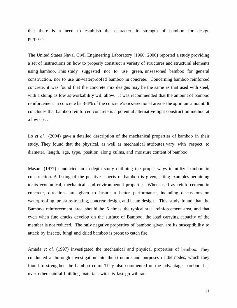
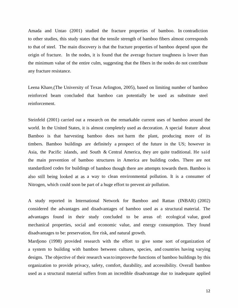
3.2.1 Preparation Bamboo Specimen
First a bamboo was divided into two piece length wise as shown in Fig. 3.1, Fig. 3.2 and Fig. 3.3
with the carpenter’s tools like hammer, chisel etc. Each of the two halves was further divided
into three pieces as shown in the Fig. 3.4. It was then cleaned and finally rounded to shape of a
rod as shown in Fig. 3.5 and Fig. 3.6.
Fig. 3.1 Hammering Bamboo with a Chisel Fig. 3.2 Hammering Bamboo Through Out its Length
15
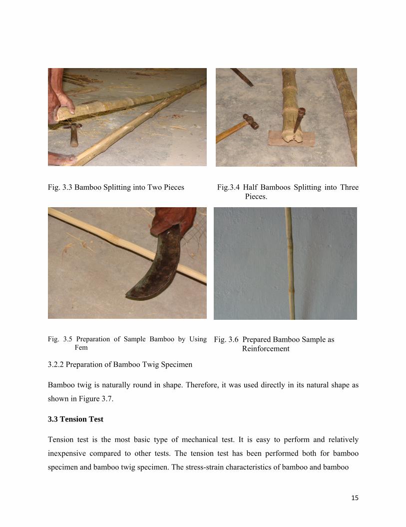
Fig. 3.3 Bamboo Splitting into Two Pieces Fig.3.4 Half Bamboos Splitting into Three Pieces.
Fig. 3.5 Preparation of Sample Bamboo by Using Fem
Fig. 3.6 Prepared Bamboo Sample as Reinforcement
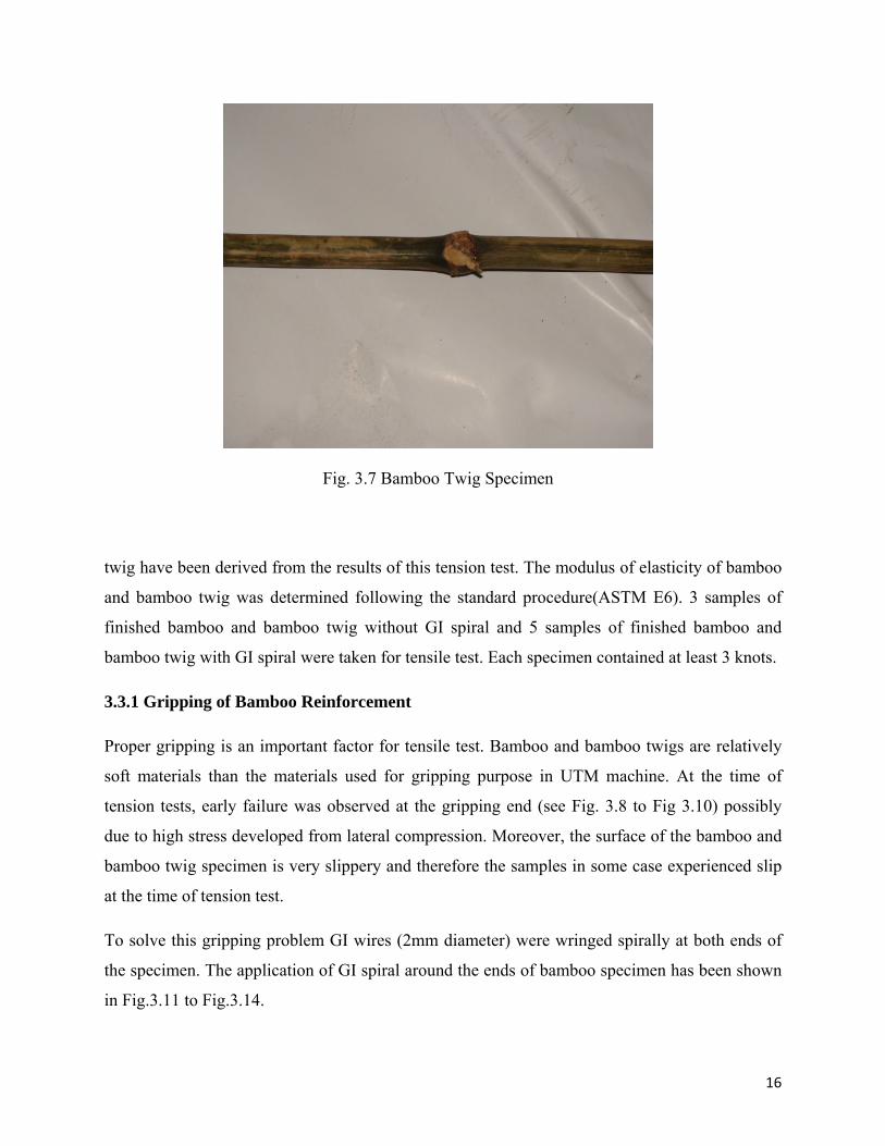
3.2.2 Preparation of Bamboo Twig Specimen
Bamboo twig is naturally round in shape. Therefore, it was used directly in its natural shape as
shown in Figure 3.7.
3.3 Tension Test
Tension test is the most basic type of mechanical test. It is easy to perform and relatively
inexpensive compared to other tests. The tension test has been performed both for bamboo
specimen and bamboo twig specimen. The stress-strain characteristics of bamboo and bamboo
16
Fig. 3.7 Bamboo Twig Specimen
twig have been derived from the results of this tension test. The modulus of elasticity of bamboo
and bamboo twig was determined following the standard procedure(ASTM E6). 3 samples of
finished bamboo and bamboo twig without GI spiral and 5 samples of finished bamboo and
bamboo twig with GI spiral were taken for tensile test. Each specimen contained at least 3 knots.
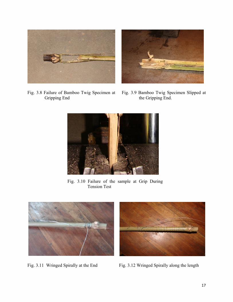
3.3.1 Gripping of Bamboo Reinforcement
Proper gripping is an important factor for tensile test. Bamboo and bamboo twigs are relatively
soft materials than the materials used for gripping purpose in UTM machine. At the time of
tension tests, early failure was observed at the gripping end (see Fig. 3.8 to Fig 3.10) possibly
due to high stress developed from lateral compression. Moreover, the surface of the bamboo and
bamboo twig specimen is very slippery and therefore the samples in some case experienced slip
at the time of tension test.
To solve this gripping problem GI wires (2mm diameter) were wringed spirally at both ends of
the specimen. The application of GI spiral around the ends of bamboo specimen has been shown
in Fig.3.11 to Fig.3.14.
17
Fig. 3.8 Failure of Bamboo Twig Specimen at
Gripping End Fig. 3.9 Bamboo Twig Specimen Slipped at
the Gripping End.
Fig. 3.10 Failure of the sample at Grip During Tension Test
Fig. 3.11 Wringed Spirally at the End Fig. 3.12 Wringed Spirally along the length
18
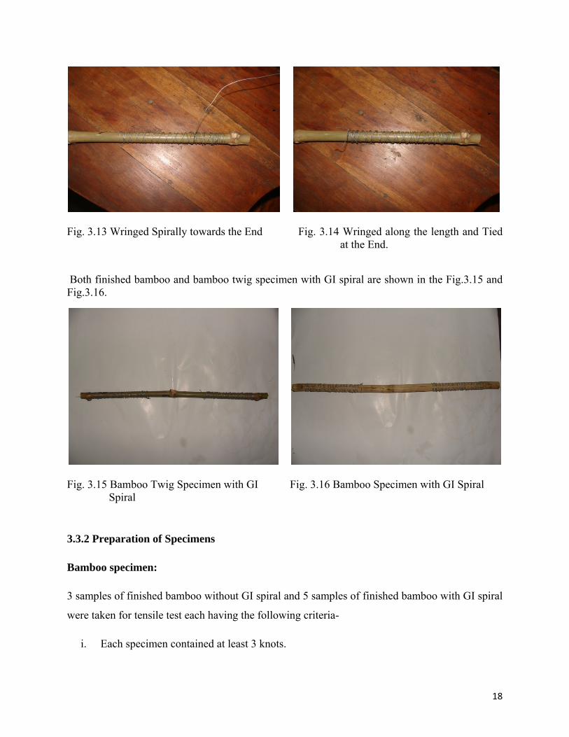
Fig. 3.13 Wringed Spirally towards the End Fig. 3.14 Wringed along the length and Tied
at the End.
Both finished bamboo and bamboo twig specimen with GI spiral are shown in the Fig.3.15 and Fig.3.16.
Fig. 3.15 Bamboo Twig Specimen with GI
Spiral Fig. 3.16 Bamboo Specimen with GI Spiral
3.3.2 Preparation of Specimens
Bamboo specimen:
3 samples of finished bamboo without GI spiral and 5 samples of finished bamboo with GI spiral
were taken for tensile test each having the following criteria-
i. Each specimen contained at least 3 knots.
19
ii. Any form of imperfection (fracture, void, decay, etc) was avoided.
iii. Any undulation was trimmed off.
iv. Diameter was measured at four different locations and then the average diameter was
calculated.
Bamboo twig specimens:
Preparation of twig specimens for each test may be done together with bamboo specimens. 3
samples of bamboo twig of natural condition and 5 samples of bamboo twig with GI. spiral were
taken for tensile test each having the following criteria-
i. Each specimen contained at least 3 knots.
ii. Any form of imperfection (fracture, void, decay, etc) was avoided
iii. Any undulation (side branches) was trimmed off.
iv. Outer diameter and inner diameter were measured at two different locations and then the
average area was calculated.
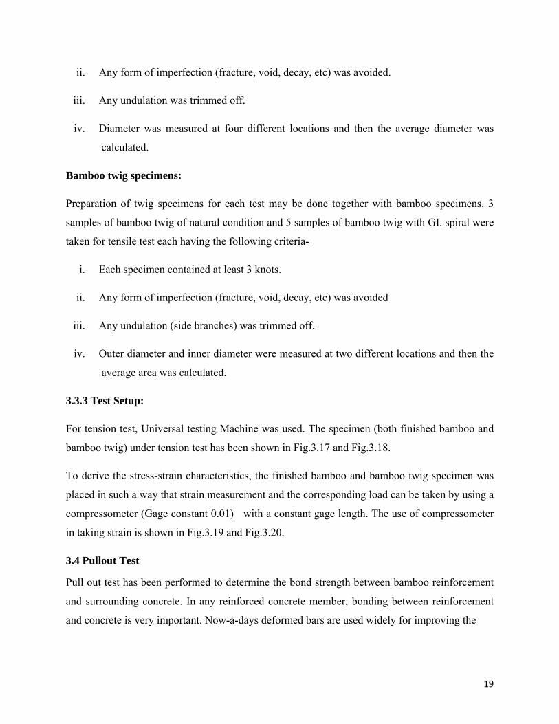
3.3.3 Test Setup:
For tension test, Universal testing Machine was used. The specimen (both finished bamboo and
bamboo twig) under tension test has been shown in Fig.3.17 and Fig.3.18.
To derive the stress-strain characteristics, the finished bamboo and bamboo twig specimen was
placed in such a way that strain measurement and the corresponding load can be taken by using a
compressometer (Gage constant 0.01) with a constant gage length. The use of compressometer
in taking strain is shown in Fig.3.19 and Fig.3.20.
3.4 Pullout Test
Pull out test has been performed to determine the bond strength between bamboo reinforcement
and surrounding concrete. In any reinforced concrete member, bonding between reinforcement
and concrete is very important. Now-a-days deformed bars are used widely for improving the
20
Fig. 3.17 Finished Bamboo Under Tension Test Fig. 3.18 Bamboo Twig Under Tension Test
Fig. 3.19 Use of Compressometer in Tension
Test of Finished Bamboo. Fig. 3.20 Use of Compressometer in Tension
Test of Finished Bamboo Twig.
bonding. On the other hand bamboo and bamboo twig have a smooth and slippery surface and
therefore bonding may be a critical factor for this kind of specimen. Therefore, it was decided to
investigate the bond strength of finished bamboo and bamboo twig by performing pull out test.
Three samples were taken in natural condition, three samples were coated with tar and three
samples were taken coated with tar and pierced nail with a length of 762 mm to 1067 mm were
taken for pullout test.
21
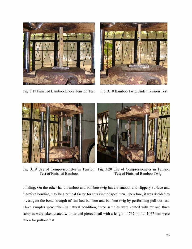
3.4.1 Preparation of Specimen
The following procedure was followed in preparation of bamboo specimens for pull out test
Bamboo specimen preparation:
i. The length of specimens is between 762 and 1067 mm.
ii. Any form of weak and decayed portions was avoided.
iii. The diameter of each specimen was measured at three locations using Slide Calipers and
the average values were calculated.
iv. Three samples were taken in natural condition as shown in the Fig.3.21
Fig. 3.21 Bamboo Sample(In Natural Condition) for Pullout Test.
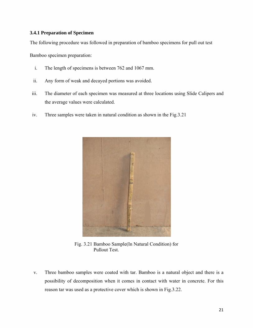
v. Three bamboo samples were coated with tar. Bamboo is a natural object and there is a
possibility of decomposition when it comes in contact with water in concrete. For this
reason tar was used as a protective cover which is shown in Fig.3.22.
22
Fig. 3.22 Bamboo Sample Coated with Tar
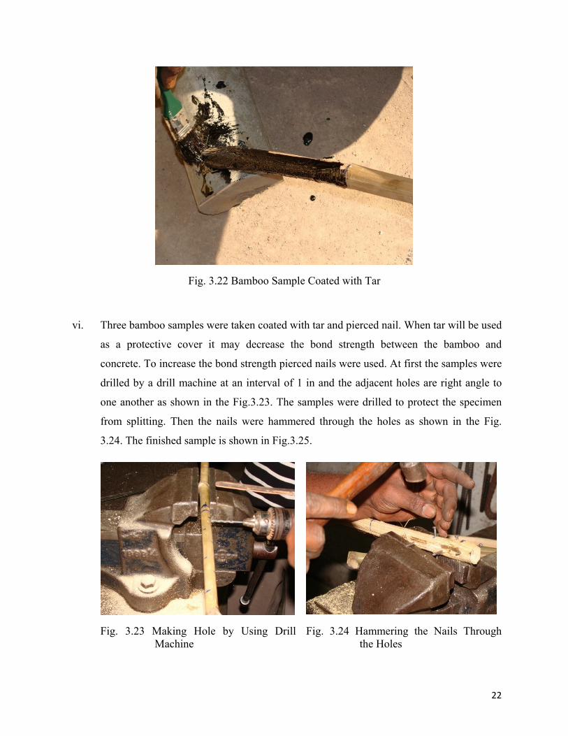
vi. Three bamboo samples were taken coated with tar and pierced nail. When tar will be used
as a protective cover it may decrease the bond strength between the bamboo and
concrete. To increase the bond strength pierced nails were used. At first the samples were
drilled by a drill machine at an interval of 1 in and the adjacent holes are right angle to
one another as shown in the Fig.3.23. The samples were drilled to protect the specimen
from splitting. Then the nails were hammered through the holes as shown in the Fig.
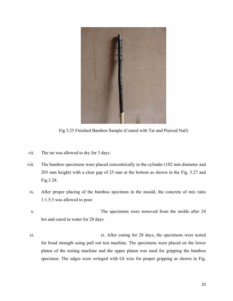
3.24. The finished sample is shown in Fig.3.25.
Fig. 3.23 Making Hole by Using Drill Machine
Fig. 3.24 Hammering the Nails Through the Holes
23
Fig 3.25 Finished Bamboo Sample (Coated with Tar and Pierced Nail)
vii. The tar was allowed to dry for 3 days.
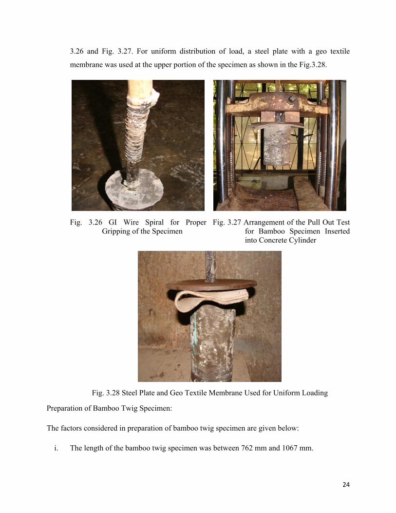
viii. The bamboo specimens were placed concentrically in the cylinder (102 mm diameter and
203 mm height) with a clear gap of 25 mm at the bottom as shown in the Fig. 3.27 and
Fig.3.28.
ix. After proper placing of the bamboo specimen in the mould, the concrete of mix ratio
1:1.5:3 was allowed to pour.
x. The specimens were removed from the molds after 24
hrs and cured in water for 28 days
xi. xi. After curing for 28 days, the specimens were tested
for bond strength using pull out test machine. The specimens were placed on the lower
platen of the testing machine and the upper platen was used for gripping the bamboo
specimen. The edges were wringed with GI wire for proper gripping as shown in Fig.
24
3.26 and Fig. 3.27. For uniform distribution of load, a steel plate with a geo textile
membrane was used at the upper portion of the specimen as shown in the Fig.3.28.
Fig. 3.26 GI Wire Spiral for Proper Gripping of the Specimen
Fig. 3.27 Arrangement of the Pull Out Test for Bamboo Specimen Inserted into Concrete Cylinder
Fig. 3.28 Steel Plate and Geo Textile Membrane Used for Uniform Loading
Preparation of Bamboo Twig Specimen:
The factors considered in preparation of bamboo twig specimen are given below:
i. The length of the bamboo twig specimen was between 762 mm and 1067 mm.
25
ii. Only straight portion of bamboo twig was chosen as specimens for testing. Any form of
imperfection or decayed portion was avoided.
iii. The outer diameter of each specimen was measured by slide calipers at three locations
and the average values were calculated.
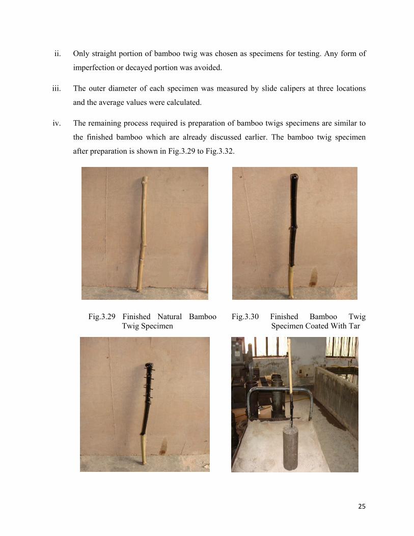
iv. The remaining process required is preparation of bamboo twigs specimens are similar to
the finished bamboo which are already discussed earlier. The bamboo twig specimen
after preparation is shown in Fig.3.29 to Fig.3.32.
Fig.3.29 Finished Natural Bamboo Twig Specimen
Fig.3.30 Finished Bamboo Twig Specimen Coated With Tar
26
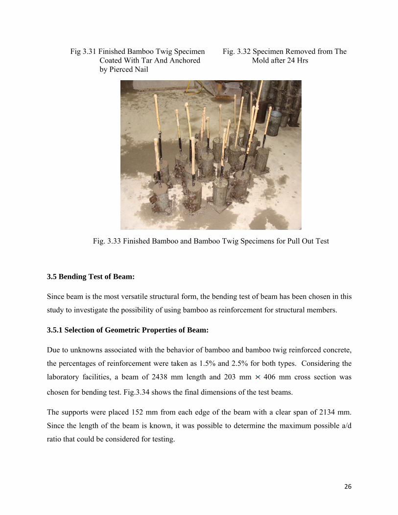
Fig 3.31 Finished Bamboo Twig Specimen Coated With Tar And Anchored by Pierced Nail
Fig. 3.32 Specimen Removed from The Mold after 24 Hrs
Fig. 3.33 Finished Bamboo and Bamboo Twig Specimens for Pull Out Test
3.5 Bending Test of Beam:
Since beam is the most versatile structural form, the bending test of beam has been chosen in this
study to investigate the possibility of using bamboo as reinforcement for structural members.
3.5.1 Selection of Geometric Properties of Beam:
Due to unknowns associated with the behavior of bamboo and bamboo twig reinforced concrete,
the percentages of reinforcement were taken as 1.5% and 2.5% for both types. Considering the
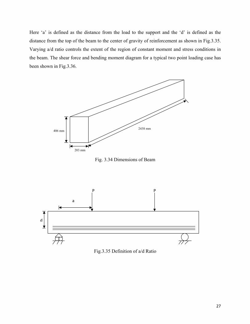
laboratory facilities, a beam of 2438 mm length and 203 mm 406 mm cross section was
chosen for bending test. Fig.3.34 shows the final dimensions of the test beams.
The supports were placed 152 mm from each edge of the beam with a clear span of 2134 mm.
Since the length of the beam is known, it was possible to determine the maximum possible a/d
ratio that could be considered for testing.
27
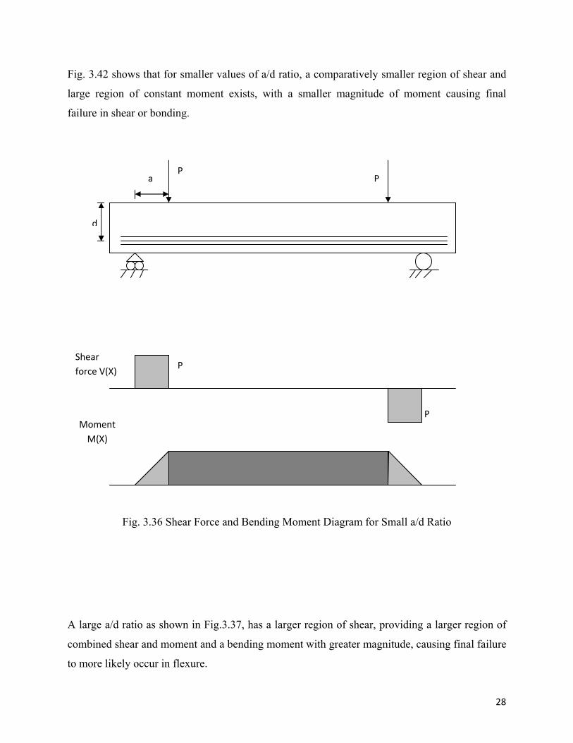
Here ‘a’ is defined as the distance from the load to the support and the ‘d’ is defined as the
distance from the top of the beam to the center of gravity of reinforcement as shown in Fig.3.35.
Varying a/d ratio controls the extent of the region of constant moment and stress conditions in
the beam. The shear force and bending moment diagram for a typical two point loading case has
been shown in Fig.3.36.
Fig. 3.34 Dimensions of Beam
Fig.3.35 Definition of a/d Ratio
203 mm
406 mm2438 mm
a
d
P P
28
Fig. 3.42 shows that for smaller values of a/d ratio, a comparatively smaller region of shear and
large region of constant moment exists, with a smaller magnitude of moment causing final
failure in shear or bonding.
Fig. 3.36 Shear Force and Bending Moment Diagram for Small a/d Ratio
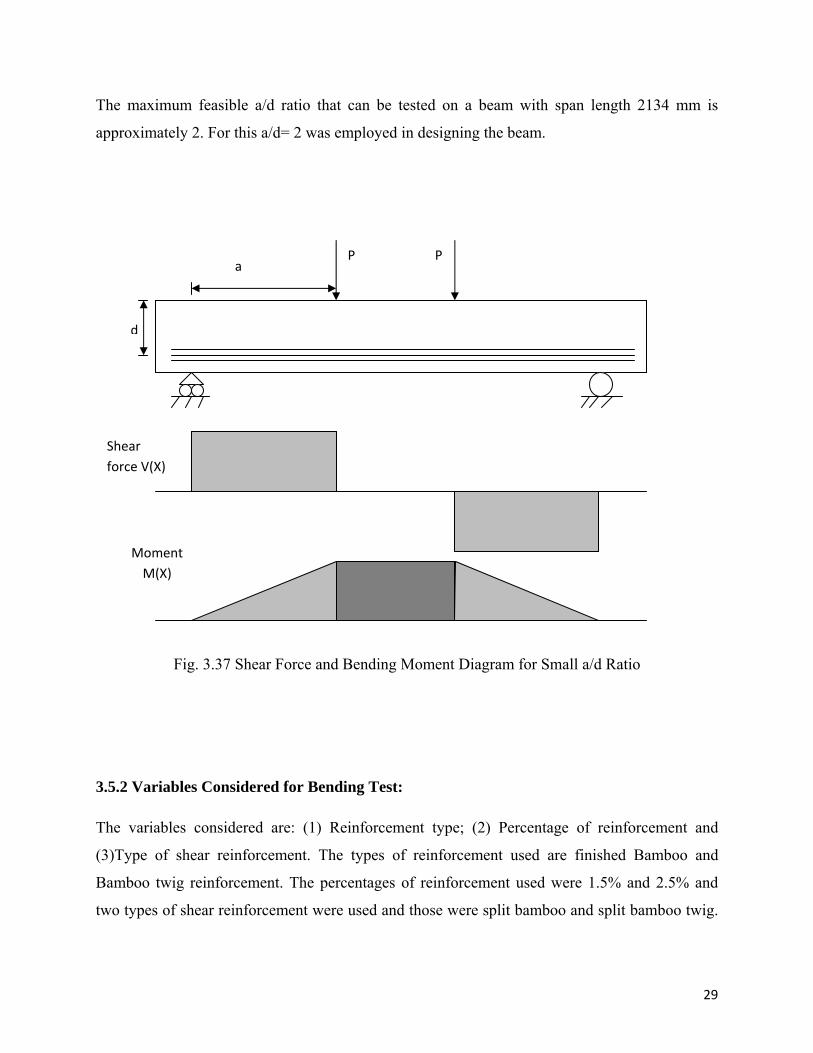
A large a/d ratio as shown in Fig.3.37, has a larger region of shear, providing a larger region of
combined shear and moment and a bending moment with greater magnitude, causing final failure
to more likely occur in flexure.
a
d
P P
P
P
Shear force V(X)
Moment M(X)
29
The maximum feasible a/d ratio that can be tested on a beam with span length 2134 mm is
approximately 2. For this a/d= 2 was employed in designing the beam.
Fig. 3.37 Shear Force and Bending Moment Diagram for Small a/d Ratio
3.5.2 Variables Considered for Bending Test:
The variables considered are: (1) Reinforcement type; (2) Percentage of reinforcement and
(3)Type of shear reinforcement. The types of reinforcement used are finished Bamboo and
Bamboo twig reinforcement. The percentages of reinforcement used were 1.5% and 2.5% and
two types of shear reinforcement were used and those were split bamboo and split bamboo twig.
a
d
P P
Shear force V(X)
Moment M(X)
30
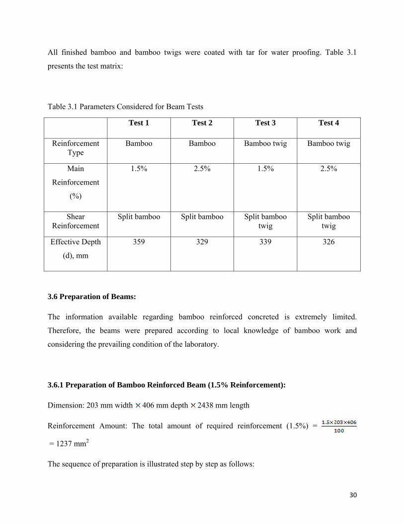
All finished bamboo and bamboo twigs were coated with tar for water proofing. Table 3.1
presents the test matrix:
Table 3.1 Parameters Considered for Beam Tests
Test 1 Test 2 Test 3 Test 4
Reinforcement Type
Bamboo Bamboo Bamboo twig Bamboo twig
Main
Reinforcement
(%)
1.5% 2.5% 1.5% 2.5%
Shear Reinforcement
Split bamboo Split bamboo Split bamboo twig
Split bamboo twig
Effective Depth
(d), mm
359 329 339 326
3.6 Preparation of Beams:
The information available regarding bamboo reinforced concreted is extremely limited.
Therefore, the beams were prepared according to local knowledge of bamboo work and
considering the prevailing condition of the laboratory.
3.6.1 Preparation of Bamboo Reinforced Beam (1.5% Reinforcement):
Dimension: 203 mm width 406 mm depth 2438 mm length
Reinforcement Amount: The total amount of required reinforcement (1.5%) =
= 1237 mm2
The sequence of preparation is illustrated step by step as follows:
31
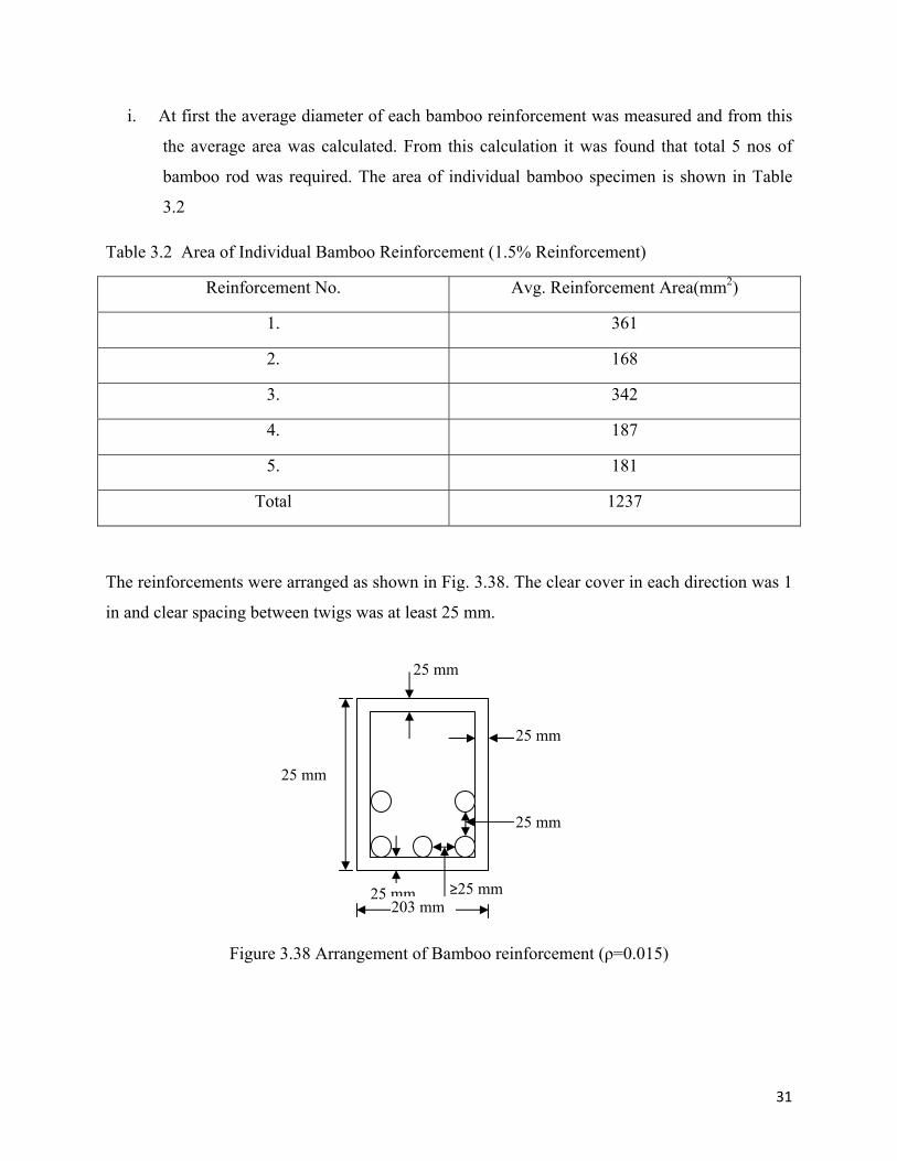
i. At first the average diameter of each bamboo reinforcement was measured and from this
the average area was calculated. From this calculation it was found that total 5 nos of
bamboo rod was required. The area of individual bamboo specimen is shown in Table
3.2
Table 3.2 Area of Individual Bamboo Reinforcement (1.5% Reinforcement)
Reinforcement No. Avg. Reinforcement Area(mm2)
1. 361
2. 168
3. 342
4. 187
5. 181
Total 1237
The reinforcements were arranged as shown in Fig. 3.38. The clear cover in each direction was 1
in and clear spacing between twigs was at least 25 mm.
Figure 3.38 Arrangement of Bamboo reinforcement (ρ=0.015)
25 mm
25 mm
25 mm
25 mm
≥25 mm
25 mm
203 mm
32
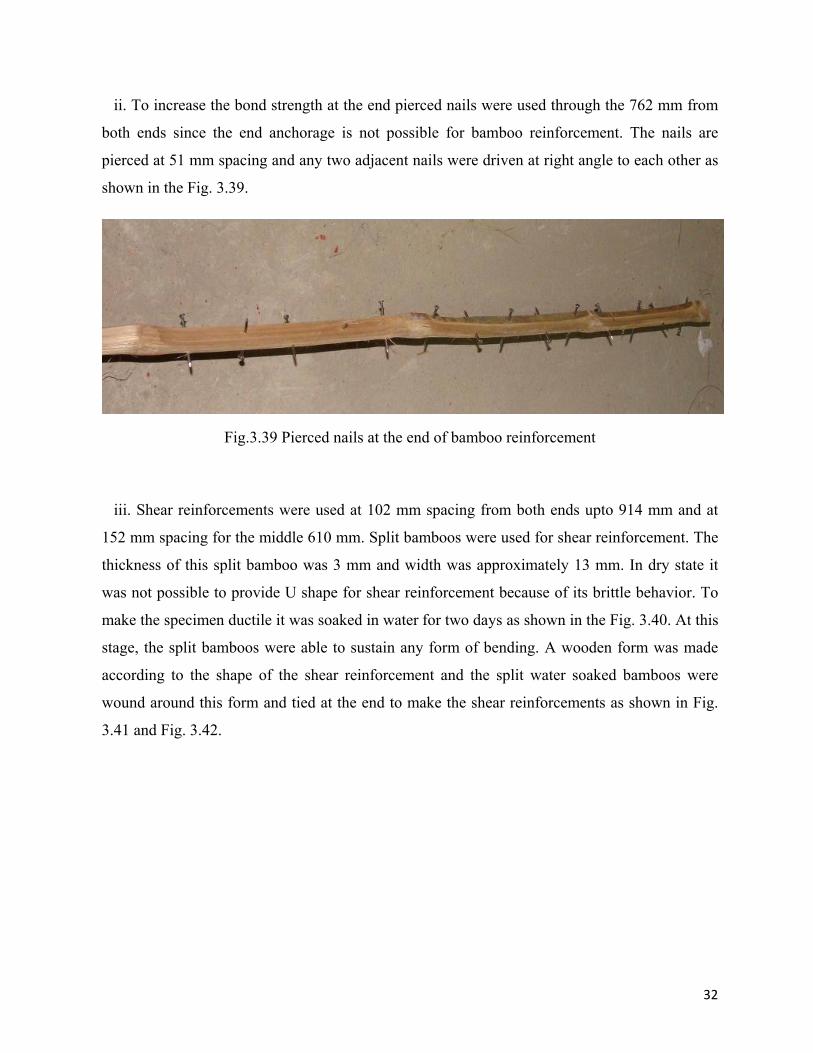
ii. To increase the bond strength at the end pierced nails were used through the 762 mm from
both ends since the end anchorage is not possible for bamboo reinforcement. The nails are
pierced at 51 mm spacing and any two adjacent nails were driven at right angle to each other as
shown in the Fig. 3.39.
Fig.3.39 Pierced nails at the end of bamboo reinforcement
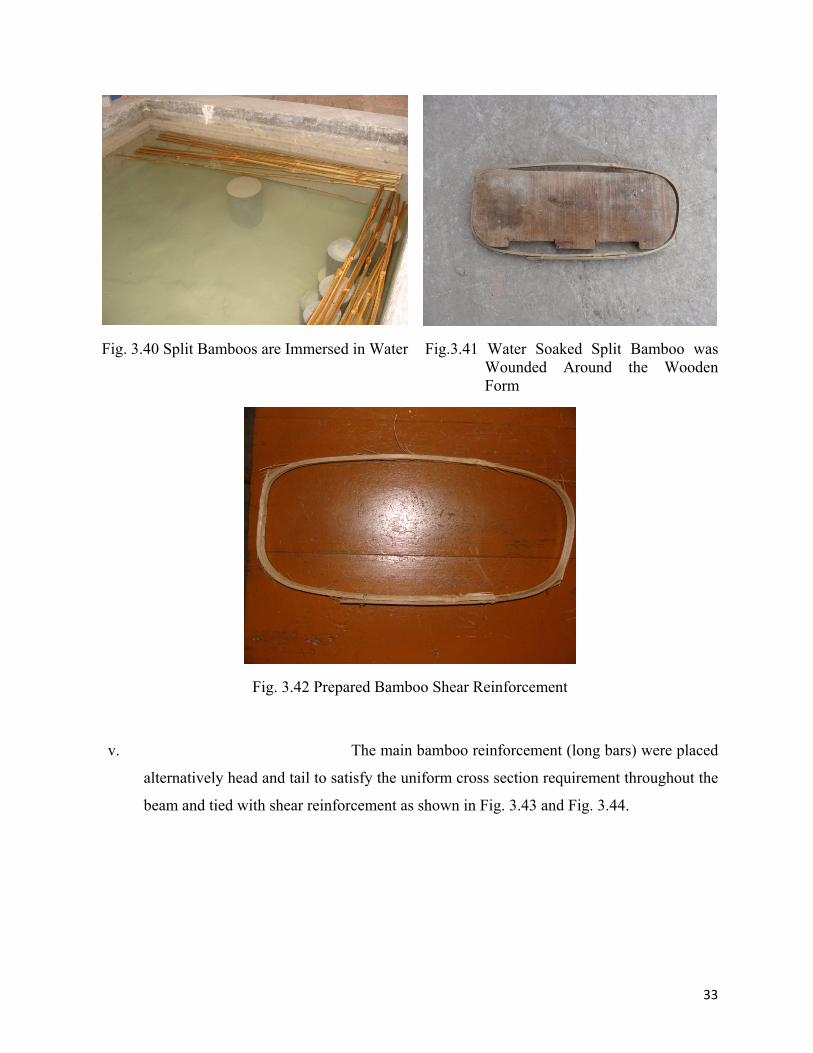
iii. Shear reinforcements were used at 102 mm spacing from both ends upto 914 mm and at
152 mm spacing for the middle 610 mm. Split bamboos were used for shear reinforcement. The
thickness of this split bamboo was 3 mm and width was approximately 13 mm. In dry state it
was not possible to provide U shape for shear reinforcement because of its brittle behavior. To
make the specimen ductile it was soaked in water for two days as shown in the Fig. 3.40. At this
stage, the split bamboos were able to sustain any form of bending. A wooden form was made
according to the shape of the shear reinforcement and the split water soaked bamboos were
wound around this form and tied at the end to make the shear reinforcements as shown in Fig.
3.41 and Fig. 3.42.
33
Fig. 3.40 Split Bamboos are Immersed in Water Fig.3.41 Water Soaked Split Bamboo was Wounded Around the Wooden Form
Fig. 3.42 Prepared Bamboo Shear Reinforcement
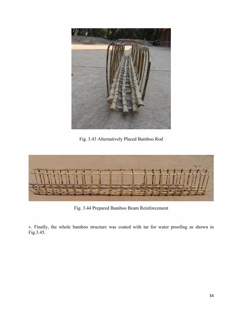
v. The main bamboo reinforcement (long bars) were placed
alternatively head and tail to satisfy the uniform cross section requirement throughout the
beam and tied with shear reinforcement as shown in Fig. 3.43 and Fig. 3.44.
34
Fig. 3.43 Alternatively Placed Bamboo Rod
Fig. 3.44 Prepared Bamboo Beam Reinforcement
v. Finally, the whole bamboo structure was coated with tar for water proofing as shown in Fig.3.45.
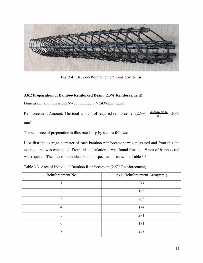
35
Fig. 3.45 Bamboo Reinforcement Coated with Tar.
3.6.2 Preparation of Bamboo Reinforced Beam (2.5% Reinforcement):
Dimension: 203 mm width 406 mm depth 2438 mm length
Reinforcement Amount: The total amount of required reinforcement(2.5%)= = 2060
mm2
The sequence of preparation is illustrated step by step as follows:
i. At first the average diameter of each bamboo reinforcement was measured and from this the
average area was calculated. From this calculation it was found that total 9 nos of bamboo rod
was required. The area of individual bamboo specimen is shown in Table 3.3
Table 3.3 Area of Individual Bamboo Reinforcement (2.5% Reinforcement)
Reinforcement No. Avg. Reinforcement Area(mm2)
1. 277
2. 168
3. 265
4. 174
5. 271
6. 181
7. 258
36
8. 206
9. 277
Total 2077
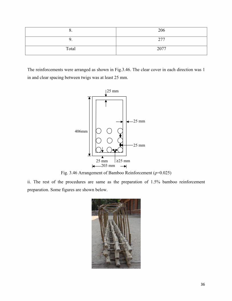
The reinforcements were arranged as shown in Fig.3.46. The clear cover in each direction was 1
in and clear spacing between twigs was at least 25 mm.
Fig. 3.46 Arrangement of Bamboo Reinforcement (ρ=0.025)
ii. The rest of the procedures are same as the preparation of 1.5% bamboo reinforcement
preparation. Some figures are shown below.
25 mm
25 mm
25 mm
25 mm
≥25 mm
406mm
203 mm
37
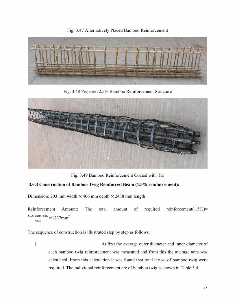
Fig. 3.47 Alternatively Placed Bamboo Reinforcement
Fig. 3.48 Prepared 2.5% Bamboo Reinforcement Structure
Fig. 3.49 Bamboo Reinforcement Coated with Tar
3.6.3 Construction of Bamboo Twig Reinforced Beam (1.5% reinforcement):
Dimension: 203 mm width 406 mm depth 2438 mm length
Reinforcement Amount: The total amount of required reinforcement(1.5%)=
=1237mm2
The sequence of construction is illustrated step by step as follows:
i. At first the average outer diameter and inner diameter of
each bamboo twig reinforcement was measured and from this the average area was
calculated. From this calculation it was found that total 9 nos. of bamboo twig were
required. The individual reinforcement are of bamboo twig is shown in Table 3.4
38
Table 3.4 Area of Bamboo Twig Reinforcement(1.5% Reinforcement)
Specimen No. Average Area of Bamboo Twig Reinforcement (mm2)
1. 103 2. 97 3. 155 4. 71 5. 168 6. 161 7. 181 8. 161 9. 155
Total 1252
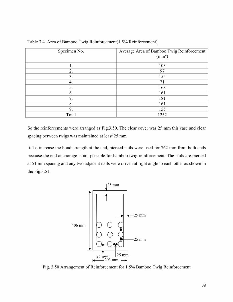
So the reinforcements were arranged as Fig.3.50. The clear cover was 25 mm this case and clear
spacing between twigs was maintained at least 25 mm.
ii. To increase the bond strength at the end, pierced nails were used for 762 mm from both ends
because the end anchorage is not possible for bamboo twig reinforcement. The nails are pierced
at 51 mm spacing and any two adjacent nails were driven at right angle to each other as shown in
the Fig.3.51.
Fig. 3.50 Arrangement of Reinforcement for 1.5% Bamboo Twig Reinforcement
25 mm
25 mm
25 mm
25 mm
25 mm
406 mm
203 mm
39
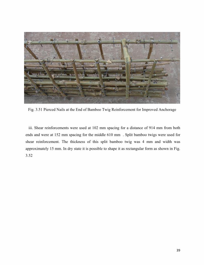
Fig. 3.51 Pierced Nails at the End of Bamboo Twig Reinforcement for Improved Anchorage
iii. Shear reinforcements were used at 102 mm spacing for a distance of 914 mm from both
ends and were at 152 mm spacing for the middle 610 mm . Split bamboo twigs were used for
shear reinforcement. The thickness of this split bamboo twig was 4 mm and width was
approximately 15 mm. In dry state it is possible to shape it as rectangular form as shown in Fig.
3.52
40
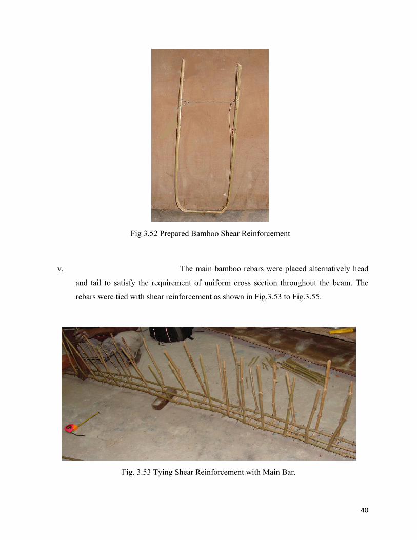
Fig 3.52 Prepared Bamboo Shear Reinforcement
v. The main bamboo rebars were placed alternatively head
and tail to satisfy the requirement of uniform cross section throughout the beam. The
rebars were tied with shear reinforcement as shown in Fig.3.53 to Fig.3.55.
Fig. 3.53 Tying Shear Reinforcement with Main Bar.
41
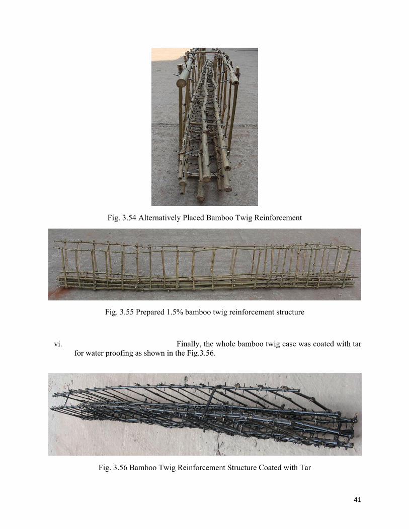
Fig. 3.54 Alternatively Placed Bamboo Twig Reinforcement
Fig. 3.55 Prepared 1.5% bamboo twig reinforcement structure
vi. Finally, the whole bamboo twig case was coated with tar for water proofing as shown in the Fig.3.56.
Fig. 3.56 Bamboo Twig Reinforcement Structure Coated with Tar
42
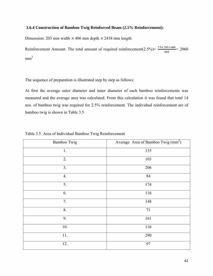
3.6.4 Construction of Bamboo Twig Reinforced Beam (2.5% Reinforcement):
Dimension: 203 mm width 406 mm depth 2438 mm length
Reinforcement Amount: The total amount of required reinforcement(2.5%)= = 2060
mm2
The sequence of preparation is illustrated step by step as follows:
At first the average outer diameter and inner diameter of each bamboo reinforcements was
measured and the average area was calculated. From this calculation it was found that total 14
nos. of bamboo twig was required for 2.5% reinforcement. The individual reinforcement are of
bamboo twig is shown in Table 3.5
Table 3.5 Area of Individual Bamboo Twig Reinforcement
Bamboo Twig Average Area of Bamboo Twig (mm2)
1. 135
2. 103
3. 206
4. 84
5. 174
6. 116
7. 148
8. 71
9. 161
10. 116
11. 290
12. 97
43
13. 258
14. 118
Total 2077
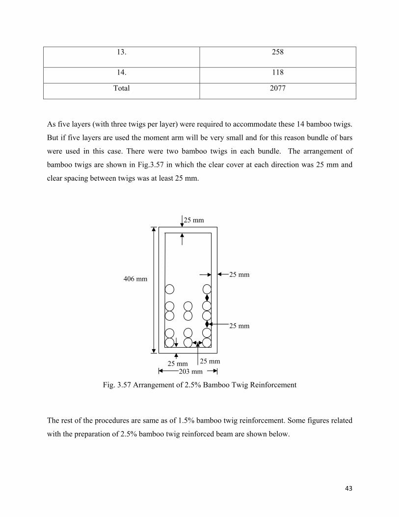
As five layers (with three twigs per layer) were required to accommodate these 14 bamboo twigs.
But if five layers are used the moment arm will be very small and for this reason bundle of bars
were used in this case. There were two bamboo twigs in each bundle. The arrangement of
bamboo twigs are shown in Fig.3.57 in which the clear cover at each direction was 25 mm and
clear spacing between twigs was at least 25 mm.
Fig. 3.57 Arrangement of 2.5% Bamboo Twig Reinforcement
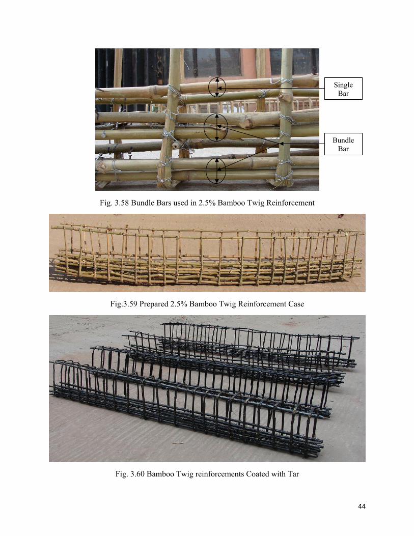
The rest of the procedures are same as of 1.5% bamboo twig reinforcement. Some figures related
with the preparation of 2.5% bamboo twig reinforced beam are shown below.
25 mm
25 mm
25 mm
25 mm
25 mm
406 mm
203 mm
44
Fig. 3.58 Bundle Bars used in 2.5% Bamboo Twig Reinforcement
Fig.3.59 Prepared 2.5% Bamboo Twig Reinforcement Case
Fig. 3.60 Bamboo Twig reinforcements Coated with Tar
Bundle Bar
Single Bar
45
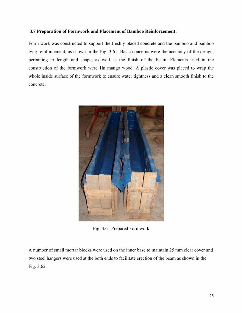
3.7 Preparation of Formwork and Placement of Bamboo Reinforcement:
Form work was constructed to support the freshly placed concrete and the bamboo and bamboo
twig reinforcement, as shown in the Fig. 3.61. Basic concerns were the accuracy of the design,
pertaining to length and shape, as well as the finish of the beam. Elements used in the
construction of the formwork were 1in mango wood. A plastic cover was placed to wrap the
whole inside surface of the formwork to ensure water tightness and a clean smooth finish to the
concrete.
Fig. 3.61 Prepared Formwork
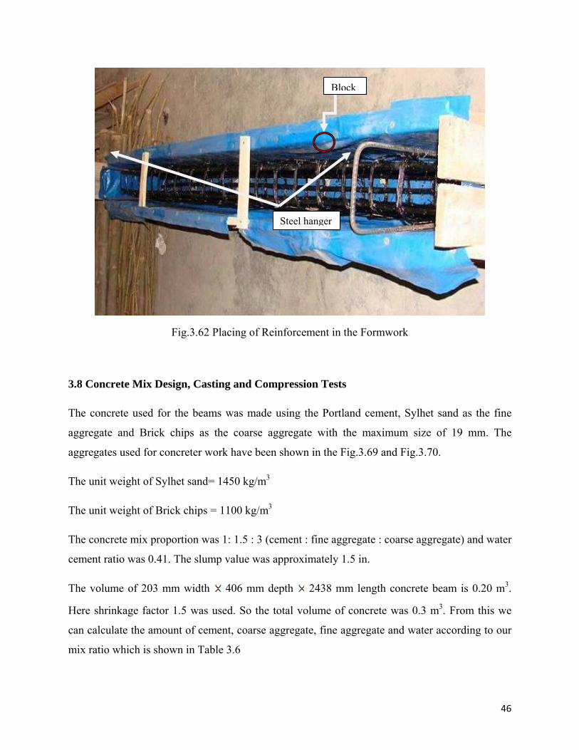
A number of small mortar blocks were used on the inner base to maintain 25 mm clear cover and
two steel hangers were used at the both ends to facilitate erection of the beam as shown in the
Fig. 3.62.
46
Fig.3.62 Placing of Reinforcement in the Formwork
3.8 Concrete Mix Design, Casting and Compression Tests
The concrete used for the beams was made using the Portland cement, Sylhet sand as the fine
aggregate and Brick chips as the coarse aggregate with the maximum size of 19 mm. The
aggregates used for concreter work have been shown in the Fig.3.69 and Fig.3.70.
The unit weight of Sylhet sand= 1450 kg/m3
The unit weight of Brick chips = 1100 kg/m3
The concrete mix proportion was 1: 1.5 : 3 (cement : fine aggregate : coarse aggregate) and water
cement ratio was 0.41. The slump value was approximately 1.5 in.
The volume of 203 mm width 406 mm depth 2438 mm length concrete beam is 0.20 m3.
Here shrinkage factor 1.5 was used. So the total volume of concrete was 0.3 m3. From this we
can calculate the amount of cement, coarse aggregate, fine aggregate and water according to our
mix ratio which is shown in Table 3.6
Steel hanger
Block
47
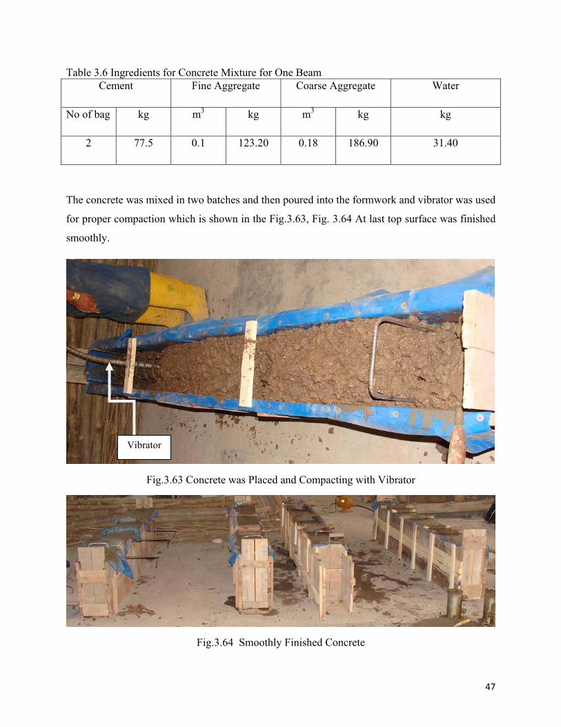
Table 3.6 Ingredients for Concrete Mixture for One Beam Cement Fine Aggregate Coarse Aggregate Water
No of bag kg m3 kg m3 kg kg
2 77.5 0.1 123.20 0.18 186.90 31.40
The concrete was mixed in two batches and then poured into the formwork and vibrator was used
for proper compaction which is shown in the Fig.3.63, Fig. 3.64 At last top surface was finished
smoothly.
Fig.3.63 Concrete was Placed and Compacting with Vibrator
Fig.3.64 Smoothly Finished Concrete
Vibrator
48
3. Cylinders (102 mm dia and 203 mm height) were also prepared (as per ASTM) for
compression tests. This was done by pouring them full of the same concrete used in the beam
and they were cured in water. The cylinder strength was taken at the day of testing of the beams.
After three days the wooden shutter was removed and covered with wet jute sack to maintain the
moisture. The beams were cured with water twice in every day until the testing date which is
shown in the Fig. 3.77.
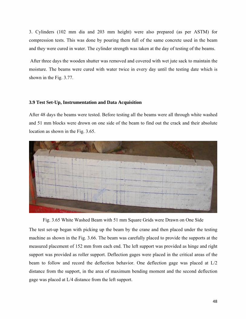
3.9 Test Set-Up, Instrumentation and Data Acquisition
After 48 days the beams were tested. Before testing all the beams were all through white washed
and 51 mm blocks were drown on one side of the beam to find out the crack and their absolute
location as shown in the Fig. 3.65.
Fig. 3.65 White Washed Beam with 51 mm Square Grids were Drawn on One Side
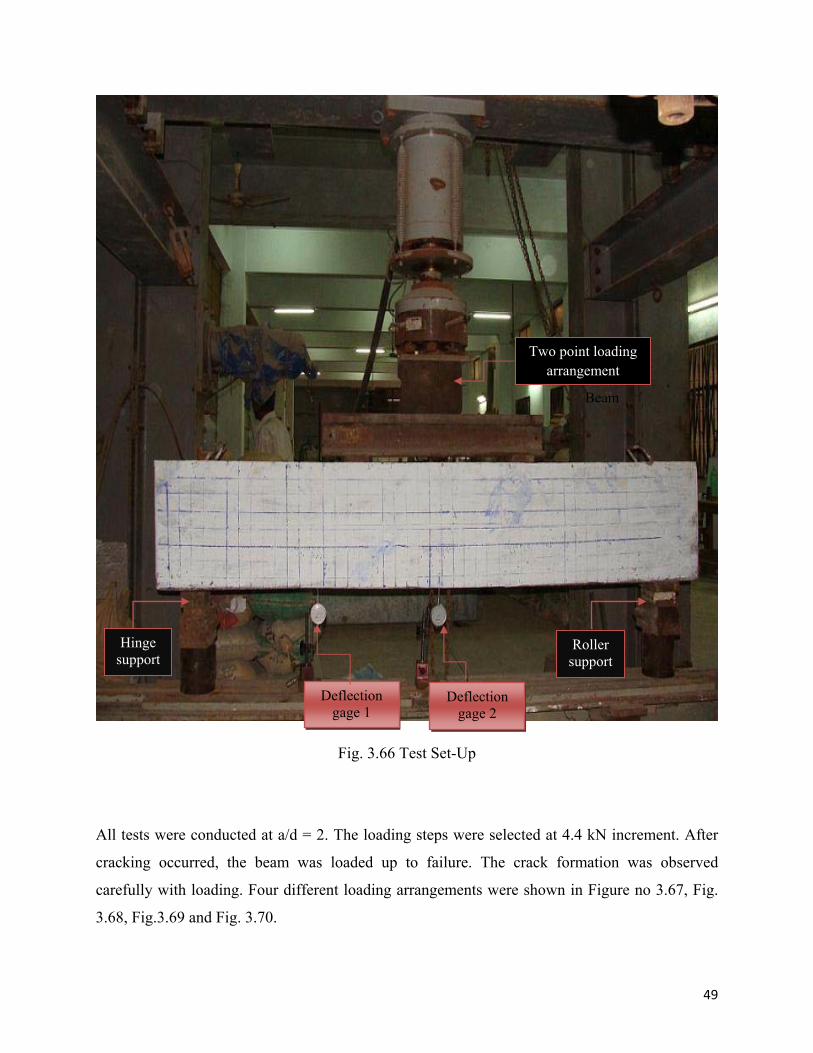
The test set-up began with picking up the beam by the crane and then placed under the testing
machine as shown in the Fig. 3.66. The beam was carefully placed to provide the supports at the
measured placement of 152 mm from each end. The left support was provided as hinge and right
support was provided as roller support. Deflection gages were placed in the critical areas of the
beam to follow and record the deflection behavior. One deflection gage was placed at L/2
distance from the support, in the area of maximum bending moment and the second deflection
gage was placed at L/4 distance from the left support.
49
Fig. 3.66 Test Set-Up
All tests were conducted at a/d = 2. The loading steps were selected at 4.4 kN increment. After
cracking occurred, the beam was loaded up to failure. The crack formation was observed
carefully with loading. Four different loading arrangements were shown in Figure no 3.67, Fig.
3.68, Fig.3.69 and Fig. 3.70.
Hinge support
Roller support
Deflection gage 2
Deflection gage 1
Two point loading arrangement
Beam
50
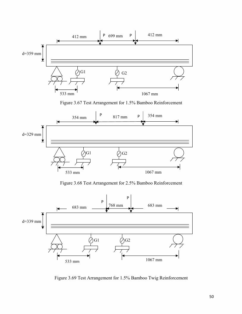
Figure 3.67 Test Arrangement for 1.5% Bamboo Reinforcement
Figure 3.68 Test Arrangement for 2.5% Bamboo Reinforcement
Figure 3.69 Test Arrangement for 1.5% Bamboo Twig Reinforcement
412 mm
d=359 mm
P P 412 mm 699 mm
533 mm 1067 mm
354 mm
d=329 mm
P P 354 mm 817 mm
533 mm 1067 mm
683 mm
d=339 mm
PP
683 mm 768 mm
533 mm 1067 mm
G1 G2
G1 G2
G1 G2
51
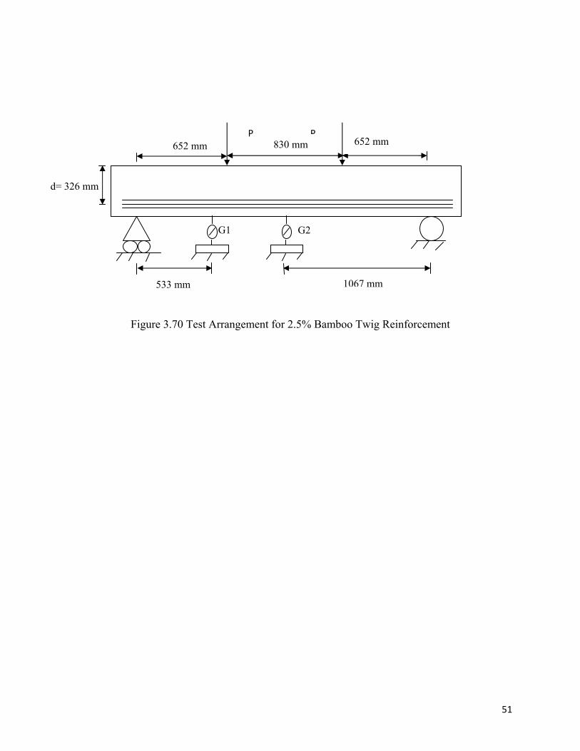
Figure 3.70 Test Arrangement for 2.5% Bamboo Twig Reinforcement
652 mm
d= 326 mm
P P652 mm 830 mm
533 mm 1067 mm
G1 G2
51
CHAPTER 4
RESULTS OF EXPERIMENTS
4.1 Introduction
This chapter presents the results of the tests that were conducted for this study. Three kinds of
tests were conducted and all the findings are thoroughly presented in this chapter. From the
tensile test the yield and the ultimate strength of bamboo and bamboo twig were determined.
Next, the pull out tests provided the bond strength of bamboo and bamboo twig with concrete
which is a very important property in reinforced concrete interaction. Finally, two point bending
beam tests were conducted with bamboo and bamboo twig reinforced concrete with a specified
a/d ratio and varying percentage of reinforcement.
4.2 Results of Tension Test for Bamboo Specimen
The tensile tests were conducted for several samples of both bamboo and bamboo twig
specimens. Their failure pattern, ultimate and yield strength will be discussed in the following
section. Tension tests were performed for specimens with different conditions of gripping.
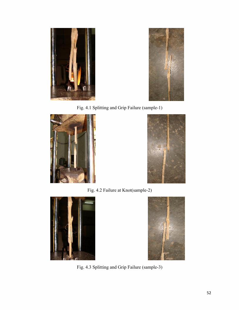
4.2.1 Results of Tension Tests for Bamboo Specimens (Normal bamboo surface at grip area)
According to the test, the splitting end grip failure was observed for sample-1(see Fig.4.1). The
splitting failure initiated at the gripping area and finally smashed. Therefore, it can be opined that
if failure at grip could have been avoided, the specimen would take more load. The sample
experienced failure at knot(see Fig.4.2) and no failure was observed at the grip and hence the
specimen carried higher load. The third sample experienced failure similar to sample-1 (see
Fig.4.3).
The failure loads of these samples are shown in Table 4.1
4.2.2 Results of Tension Tests for Bamboo Specimens (Bamboo surface with GI wire at grip
area)
During tension tests of bamboo reinforcement, an attempt was made to avoid failure at the grip
by wrapping the ends by GI wire as shown in Fig.4.4.
52
Fig. 4.1 Splitting and Grip Failure (sample-1)
Fig. 4.2 Failure at Knot(sample-2)
Fig. 4.3 Splitting and Grip Failure (sample-3)
53
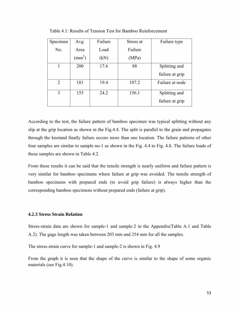
Table 4.1: Results of Tension Test for Bamboo Reinforcement
Specimen
No.
Avg.
Area
(mm2)
Failure
Load
(kN)
Stress at
Failure
(MPa)
Failure type
1 200 17.6 88 Splitting and
failure at grip
2 181 19.4 107.2 Failure at node
3 155 24.2 156.1 Splitting and
failure at grip
According to the test, the failure pattern of bamboo specimen was typical splitting without any
slip at the grip location as shown in the Fig.4.4. The split is parallel to the grain and propagates
through the knotand finally failure occurs more than one location. The failure patterns of other
four samples are similar to sample no-1 as shown in the Fig. 4.4 to Fig. 4.8. The failure loads of
these samples are shown in Table 4.2.
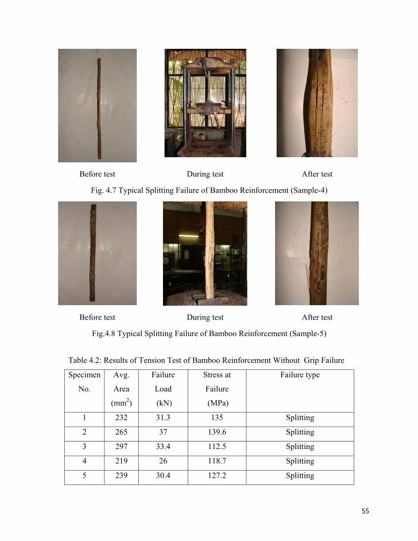
From these results it can be said that the tensile strength is nearly uniform and failure pattern is
very similar for bamboo specimens where failure at grip was avoided. The tensile strength of
bamboo specimens with prepared ends (to avoid grip failure) is always higher than the
corresponding bamboo specimens without prepared ends (failure at grip).
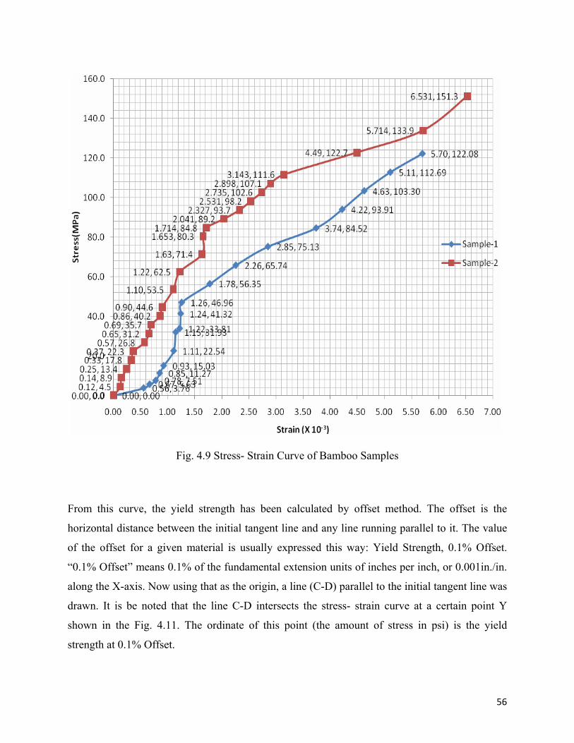
4.2.3 Stress Strain Relation
Stress-strain data are shown for sample-1 and sample-2 in the Appendix(Table A.1 and Table
A.2). The gage length was taken between 203 mm and 254 mm for all the samples.
The stress-strain curve for sample-1 and sample-2 is shown in Fig. 4.9
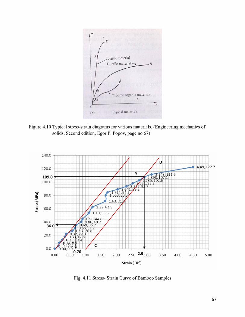
From the graph it is seen that the shape of the curve is similar to the shape of some organic materials (see Fig.4.10).
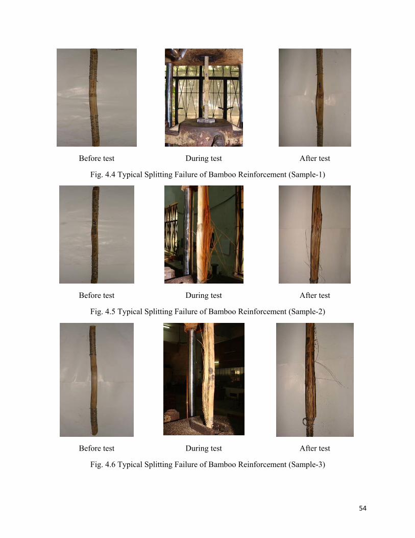
54
Before test During test After test
Fig. 4.4 Typical Splitting Failure of Bamboo Reinforcement (Sample-1)
Before test During test After test
Fig. 4.5 Typical Splitting Failure of Bamboo Reinforcement (Sample-2)
Before test During test After test
Fig. 4.6 Typical Splitting Failure of Bamboo Reinforcement (Sample-3)
55
Before test During test After test
Fig. 4.7 Typical Splitting Failure of Bamboo Reinforcement (Sample-4)
Before test During test After test
Fig.4.8 Typical Splitting Failure of Bamboo Reinforcement (Sample-5)
Table 4.2: Results of Tension Test of Bamboo Reinforcement Without Grip Failure
Specimen
No.
Avg.
Area
(mm2)
Failure
Load
(kN)
Stress at
Failure
(MPa)
Failure type
1 232 31.3 135 Splitting
2 265 37 139.6 Splitting
3 297 33.4 112.5 Splitting
4 219 26 118.7 Splitting
5 239 30.4 127.2 Splitting
56
From this curve, the yield strength has been calculated by offset method. The offset is the
horizontal distance between the initial tangent line and any line running parallel to it. The value
of the offset for a given material is usually expressed this way: Yield Strength, 0.1% Offset.
“0.1% Offset” means 0.1% of the fundamental extension units of inches per inch, or 0.001in./in.
along the X-axis. Now using that as the origin, a line (C-D) parallel to the initial tangent line was
drawn. It is be noted that the line C-D intersects the stress- strain curve at a certain point Y
shown in the Fig. 4.11. The ordinate of this point (the amount of stress in psi) is the yield
strength at 0.1% Offset.
Fig. 4.9 Stress- Strain Curve of Bamboo Samples
57
Figure 4.10 Typical stress-strain diagrams for various materials. (Engineering mechanics of solids, Second edition, Egor P. Popov, page no 67)
Fig. 4.11 Stress- Strain Curve of Bamboo Samples
Y
C
D
2.9
109.0
36.0
0.70
58
Therefore, from this method, the yield strength fy = 109 MPa.
To be on the conservative side the value of fy=105.7 MPa was used to calculate the cracking load
and also the ultimate load that the bamboo reinforced beam can sustain.
The modulus of elasticity was found to be 51428.6 MPa.
4.3 Results of Tension Test for Bamboo Twig Specimen
The tensile tests were conducted for several samples of bamboo twig specimens. Their failure
pattern, ultimate and yield strength will be discussed in the following section. Tension tests were
performed for specimens with different conditions of gripping.
4.3.1 Results of Tension Tests for Bamboo Twig Specimens (Normal bamboo surface at grip
area)
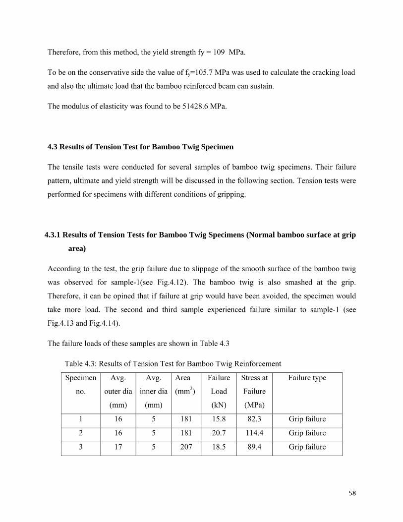
According to the test, the grip failure due to slippage of the smooth surface of the bamboo twig
was observed for sample-1(see Fig.4.12). The bamboo twig is also smashed at the grip.
Therefore, it can be opined that if failure at grip would have been avoided, the specimen would
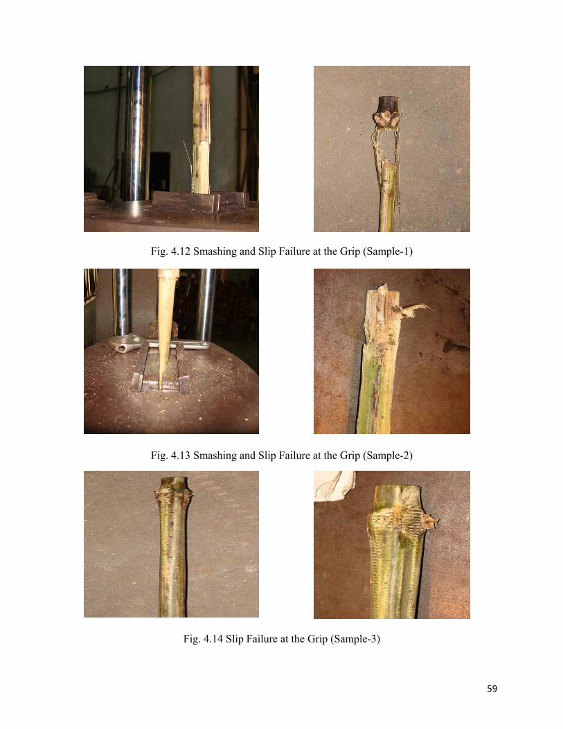
take more load. The second and third sample experienced failure similar to sample-1 (see
Fig.4.13 and Fig.4.14).
The failure loads of these samples are shown in Table 4.3
Table 4.3: Results of Tension Test for Bamboo Twig Reinforcement
Specimen
no.
Avg.
outer dia
(mm)
Avg.
inner dia
(mm)
Area
(mm2)
Failure
Load
(kN)
Stress at
Failure
(MPa)
Failure type
1 16 5 181 15.8 82.3 Grip failure
2 16 5 181 20.7 114.4 Grip failure
3 17 5 207 18.5 89.4 Grip failure
59
Fig. 4.12 Smashing and Slip Failure at the Grip (Sample-1)
Fig. 4.13 Smashing and Slip Failure at the Grip (Sample-2)
Fig. 4.14 Slip Failure at the Grip (Sample-3)
60
4.3.2 Results of Tension Tests for Bamboo Twig Specimens (Bamboo surface with GI wire
at grip area)
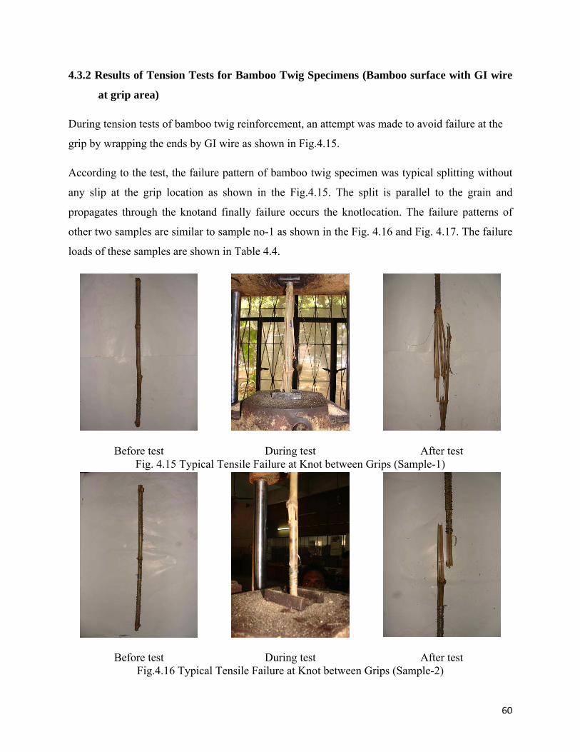
During tension tests of bamboo twig reinforcement, an attempt was made to avoid failure at the
grip by wrapping the ends by GI wire as shown in Fig.4.15.
According to the test, the failure pattern of bamboo twig specimen was typical splitting without
any slip at the grip location as shown in the Fig.4.15. The split is parallel to the grain and
propagates through the knotand finally failure occurs the knotlocation. The failure patterns of
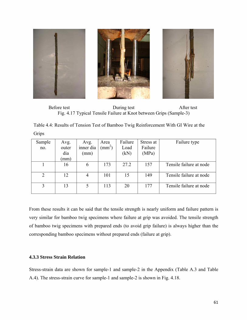
other two samples are similar to sample no-1 as shown in the Fig. 4.16 and Fig. 4.17. The failure
loads of these samples are shown in Table 4.4.
Before test During test After test
Fig. 4.15 Typical Tensile Failure at Knot between Grips (Sample-1)
Before test During test After test
Fig.4.16 Typical Tensile Failure at Knot between Grips (Sample-2)
61
Before test During test After test
Fig. 4.17 Typical Tensile Failure at Knot between Grips (Sample-3)
Table 4.4: Results of Tension Test of Bamboo Twig Reinforcement With GI Wire at the
Grips
Sample no.
Avg. outer dia
(mm)
Avg. inner dia
(mm)
Area (mm2)
Failure Load (kN)
Stress at Failure (MPa)
Failure type
1 16 6 173 27.2 157 Tensile failure at node
2 12 4 101 15 149 Tensile failure at node
3 13 5 113 20 177 Tensile failure at node
From these results it can be said that the tensile strength is nearly uniform and failure pattern is
very similar for bamboo twig specimens where failure at grip was avoided. The tensile strength
of bamboo twig specimens with prepared ends (to avoid grip failure) is always higher than the
corresponding bamboo specimens without prepared ends (failure at grip).
4.3.3 Stress Strain Relation
Stress-strain data are shown for sample-1 and sample-2 in the Appendix (Table A.3 and Table
A.4). The stress-strain curve for sample-1 and sample-2 is shown in Fig. 4.18.
62
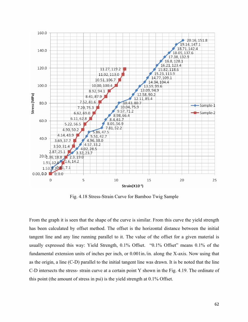
Fig. 4.18 Stress-Strain Curve for Bamboo Twig Sample
From the graph it is seen that the shape of the curve is similar. From this curve the yield strength
has been calculated by offset method. The offset is the horizontal distance between the initial
tangent line and any line running parallel to it. The value of the offset for a given material is
usually expressed this way: Yield Strength, 0.1% Offset. “0.1% Offset” means 0.1% of the
fundamental extension units of inches per inch, or 0.001in./in. along the X-axis. Now using that
as the origin, a line (C-D) parallel to the initial tangent line was drawn. It is be noted that the line
C-D intersects the stress- strain curve at a certain point Y shown in the Fig. 4.19. The ordinate of
this point (the amount of stress in psi) is the yield strength at 0.1% Offset.
63
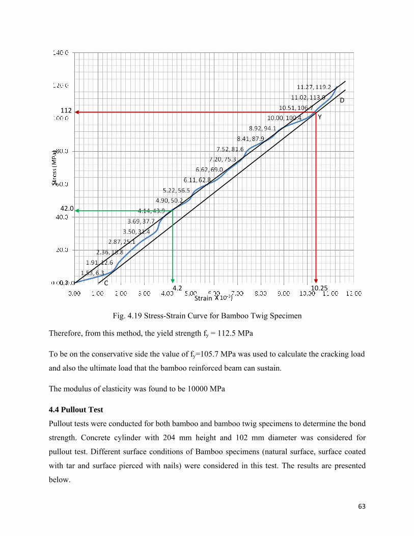
Fig. 4.19 Stress-Strain Curve for Bamboo Twig Specimen
Therefore, from this method, the yield strength fy = 112.5 MPa
To be on the conservative side the value of fy=105.7 MPa was used to calculate the cracking load
and also the ultimate load that the bamboo reinforced beam can sustain.
The modulus of elasticity was found to be 10000 MPa
4.4 Pullout Test
Pullout tests were conducted for both bamboo and bamboo twig specimens to determine the bond
strength. Concrete cylinder with 204 mm height and 102 mm diameter was considered for
pullout test. Different surface conditions of Bamboo specimens (natural surface, surface coated
with tar and surface pierced with nails) were considered in this test. The results are presented
below.
112
42.0
4.2 10.25
D
Y
C
Strain
64
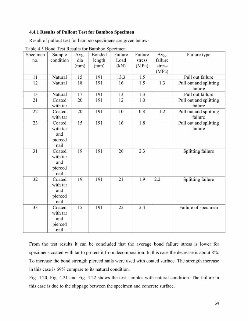
4.4.1 Results of Pullout Test for Bamboo Specimen
Result of pullout test for bamboo specimens are given below-
Table 4.5 Bond Test Results for Bamboo Specimen Specimen
no. Sample
condition Avg. dia
(mm)
Bonded length (mm)
Failure Load (kN)
Failure stress (MPa)
Avg. failure stress (MPa)
Failure type
11 Natural 15 191 13.3 1.5 Pull out failure 12 Natural 18 191 16 1.5 1.3 Pull out and splitting
failure 13 Natural 17 191 13 1.3 Pull out failure 21 Coated
with tar 20 191 12 1.0 Pull out and splitting
failure 22 Coated
with tar 20 191 10 0.8 1.2 Pull out and splitting
failure 23 Coated
with tar and
pierced nail
15 191 16 1.8 Pull out and splitting failure
31 Coated with tar
and pierced
nail
19 191 26 2.3 Splitting failure
32 Coated with tar
and pierced
nail
19 191 21 1.9 2.2 Splitting failure
33 Coated with tar
and pierced
nail
15 191 22 2.4 Failure of specimen
From the test results it can be concluded that the average bond failure stress is lower for
specimens coated with tar to protect it from decomposition. In this case the decrease is about 8%.
To increase the bond strength pierced nails were used with coated surface. The strength increase
in this case is 69% compare to its natural condition.
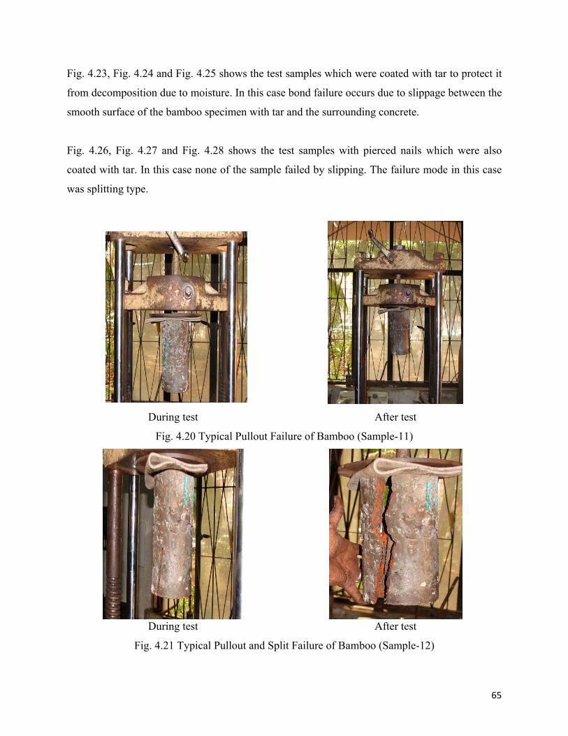
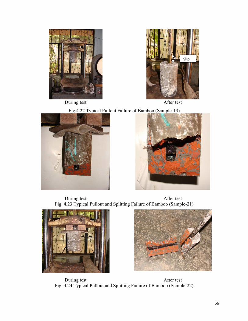
Fig. 4.20, Fig. 4.21 and Fig. 4.22 shows the test samples with natural condition. The failure in
this case is due to the slippage between the specimen and concrete surface.
65
Fig. 4.23, Fig. 4.24 and Fig. 4.25 shows the test samples which were coated with tar to protect it
from decomposition due to moisture. In this case bond failure occurs due to slippage between the
smooth surface of the bamboo specimen with tar and the surrounding concrete.
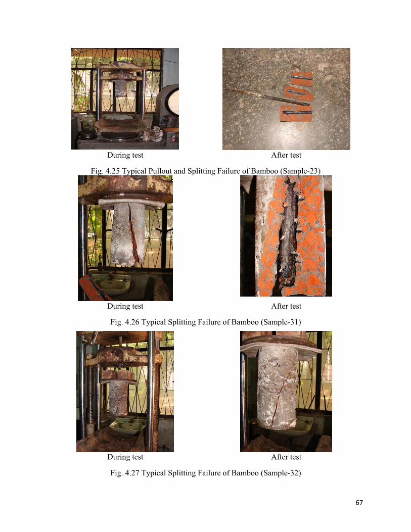
Fig. 4.26, Fig. 4.27 and Fig. 4.28 shows the test samples with pierced nails which were also
coated with tar. In this case none of the sample failed by slipping. The failure mode in this case
was splitting type.
During test After test
Fig. 4.20 Typical Pullout Failure of Bamboo (Sample-11)
During test After test
Fig. 4.21 Typical Pullout and Split Failure of Bamboo (Sample-12)
66
During test After test
Fig.4.22 Typical Pullout Failure of Bamboo (Sample-13)
During test After test Fig. 4.23 Typical Pullout and Splitting Failure of Bamboo (Sample-21)
During test After test
Fig. 4.24 Typical Pullout and Splitting Failure of Bamboo (Sample-22)
Slip
67
During test After test
Fig. 4.25 Typical Pullout and Splitting Failure of Bamboo (Sample-23)
During test After test
Fig. 4.26 Typical Splitting Failure of Bamboo (Sample-31)
During test After test
Fig. 4.27 Typical Splitting Failure of Bamboo (Sample-32)
68
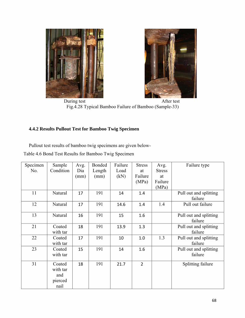
During test After test Fig.4.28 Typical Bamboo Failure of Bamboo (Sample-33)
4.4.2 Results Pullout Test for Bamboo Twig Specimen
Pullout test results of bamboo twig specimens are given below-
Table 4.6 Bond Test Results for Bamboo Twig Specimen Specimen
No. Sample
Condition Avg. Dia
(mm)
Bonded Length (mm)
Failure Load (kN)
Stress at
Failure (MPa)
Avg. Stress
at Failure (MPa)
Failure type
11 Natural 17 191 14 1.4 Pull out and splitting failure
12 Natural 17 191 14.6 1.4 1.4 Pull out failure
13 Natural 16 191 15 1.6 Pull out and splitting failure
21 Coated with tar
18 191 13.9 1.3 Pull out and splitting failure
22 Coated with tar
17 191 10 1.0 1.3 Pull out and splitting failure
23 Coated with tar
15 191 14 1.6 Pull out and splitting failure
31 Coated with tar
and pierced
nail
18 191 21.7 2 Splitting failure
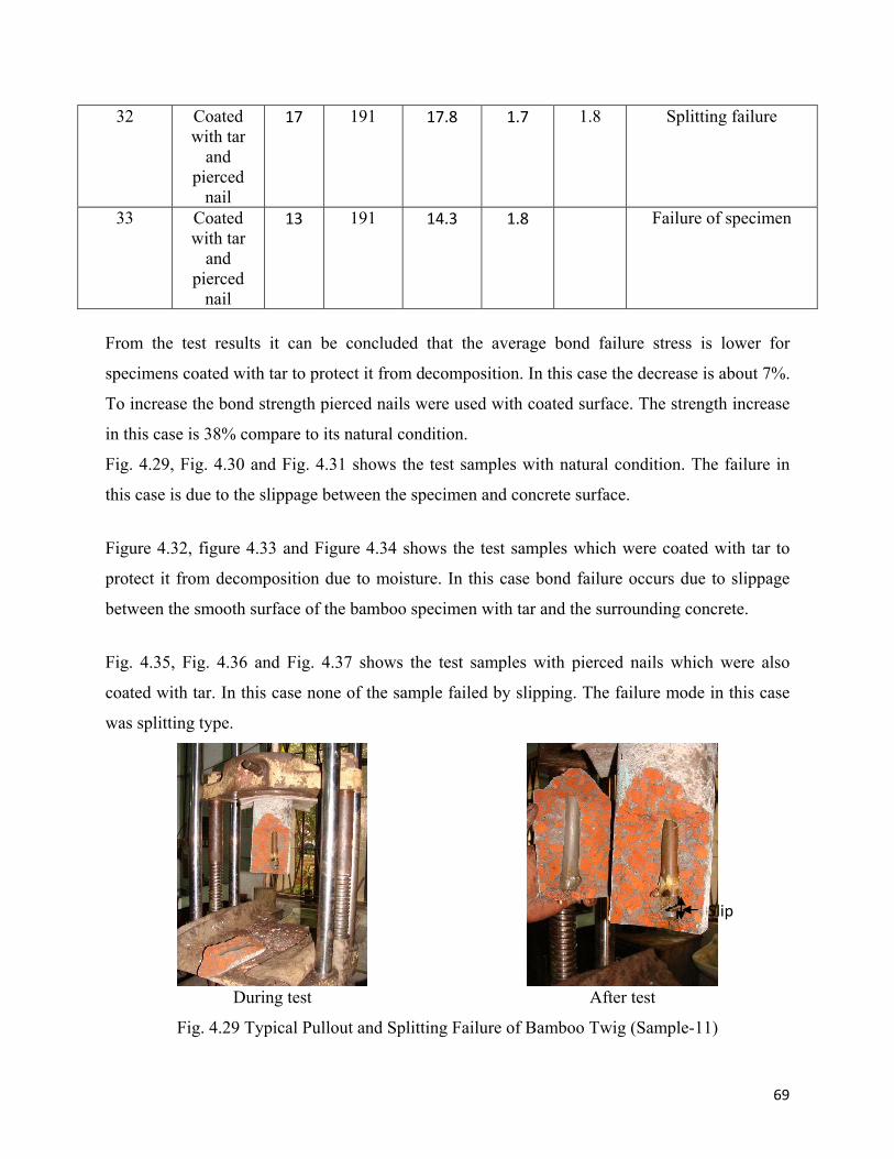
69
32 Coated with tar
and pierced
nail
17 191 17.8 1.7 1.8
Splitting failure
33 Coated with tar
and pierced
nail
13 191 14.3 1.8 Failure of specimen
From the test results it can be concluded that the average bond failure stress is lower for
specimens coated with tar to protect it from decomposition. In this case the decrease is about 7%.
To increase the bond strength pierced nails were used with coated surface. The strength increase
in this case is 38% compare to its natural condition.
Fig. 4.29, Fig. 4.30 and Fig. 4.31 shows the test samples with natural condition. The failure in
this case is due to the slippage between the specimen and concrete surface.
Figure 4.32, figure 4.33 and Figure 4.34 shows the test samples which were coated with tar to
protect it from decomposition due to moisture. In this case bond failure occurs due to slippage
between the smooth surface of the bamboo specimen with tar and the surrounding concrete.
Fig. 4.35, Fig. 4.36 and Fig. 4.37 shows the test samples with pierced nails which were also
coated with tar. In this case none of the sample failed by slipping. The failure mode in this case
was splitting type.
During test After test
Fig. 4.29 Typical Pullout and Splitting Failure of Bamboo Twig (Sample-11)
Slip
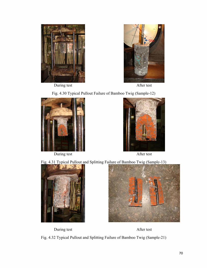
70
During test After test
Fig. 4.30 Typical Pullout Failure of Bamboo Twig (Sample-12)
During test After test
Fig. 4.31 Typical Pullout and Splitting Failure of Bamboo Twig (Sample-13)
During test After test
Fig. 4.32 Typical Pullout and Splitting Failure of Bamboo Twig (Sample-21)
Slip
slip
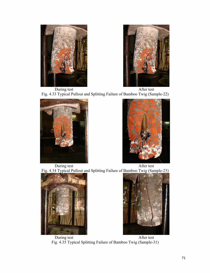
71
During test After test Fig. 4.33 Typical Pullout and Splitting Failure of Bamboo Twig (Sample-22)
During test After test Fig. 4.34 Typical Pullout and Splitting Failure of Bamboo Twig (Sample-23)
During test After test Fig. 4.35 Typical Splitting Failure of Bamboo Twig (Sample-31)
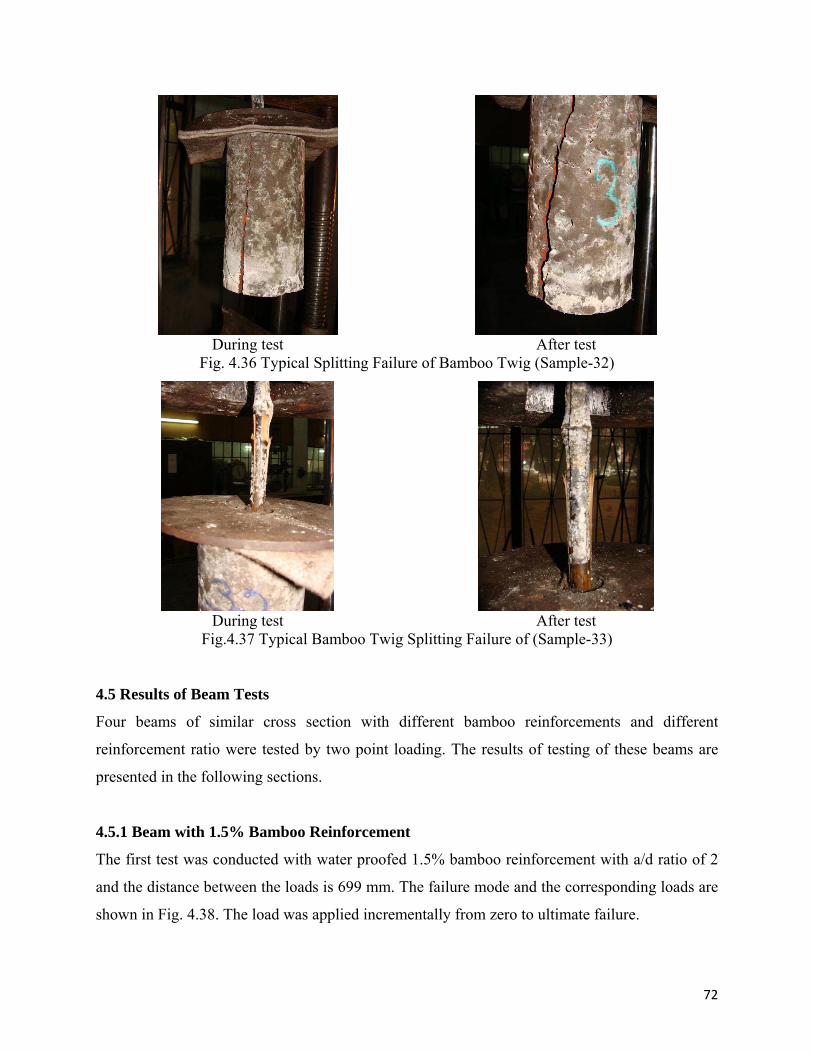
72
During test After test Fig. 4.36 Typical Splitting Failure of Bamboo Twig (Sample-32)
During test After test Fig.4.37 Typical Bamboo Twig Splitting Failure of (Sample-33)
4.5 Results of Beam Tests
Four beams of similar cross section with different bamboo reinforcements and different
reinforcement ratio were tested by two point loading. The results of testing of these beams are
presented in the following sections.
4.5.1 Beam with 1.5% Bamboo Reinforcement
The first test was conducted with water proofed 1.5% bamboo reinforcement with a/d ratio of 2
and the distance between the loads is 699 mm. The failure mode and the corresponding loads are
shown in Fig. 4.38. The load was applied incrementally from zero to ultimate failure.
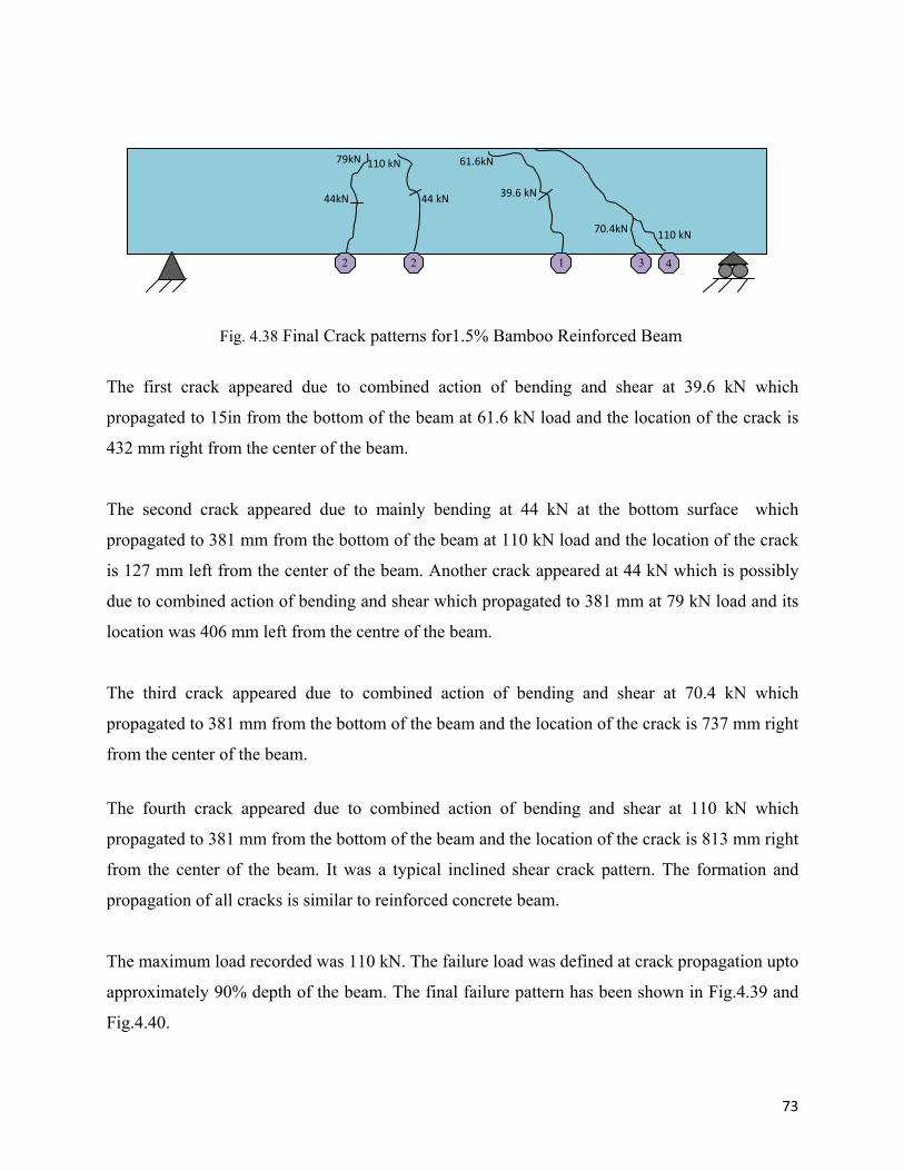
73
The first crack appeared due to combined action of bending and shear at 39.6 kN which
propagated to 15in from the bottom of the beam at 61.6 kN load and the location of the crack is
432 mm right from the center of the beam.
The second crack appeared due to mainly bending at 44 kN at the bottom surface which
propagated to 381 mm from the bottom of the beam at 110 kN load and the location of the crack
is 127 mm left from the center of the beam. Another crack appeared at 44 kN which is possibly
due to combined action of bending and shear which propagated to 381 mm at 79 kN load and its
location was 406 mm left from the centre of the beam.
The third crack appeared due to combined action of bending and shear at 70.4 kN which
propagated to 381 mm from the bottom of the beam and the location of the crack is 737 mm right
from the center of the beam.
The fourth crack appeared due to combined action of bending and shear at 110 kN which
propagated to 381 mm from the bottom of the beam and the location of the crack is 813 mm right
from the center of the beam. It was a typical inclined shear crack pattern. The formation and
propagation of all cracks is similar to reinforced concrete beam.
The maximum load recorded was 110 kN. The failure load was defined at crack propagation upto
approximately 90% depth of the beam. The final failure pattern has been shown in Fig.4.39 and
Fig.4.40.
Fig. 4.38 Final Crack patterns for1.5% Bamboo Reinforced Beam
44 kN
110 kN
44kN
79kN
39.6 kN
61.6kN
70.4kN 110 kN
2 2 1 3 4
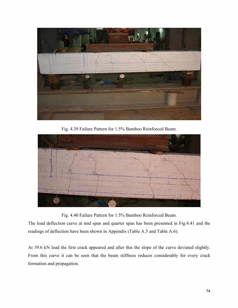
74
Fig. 4.39 Failure Pattern for 1.5% Bamboo Reinforced Beam.
Fig. 4.40 Failure Pattern for 1.5% Bamboo Reinforced Beam.
The load deflection curve at mid span and quarter span has been presented in Fig.4.41 and the
readings of deflection have been shown in Appendix (Table A.5 and Table A.6).
At 39.6 kN load the first crack appeared and after this the slope of the curve deviated slightly.
From this curve it can be seen that the beam stiffness reduces considerably for every crack
formation and propagation.
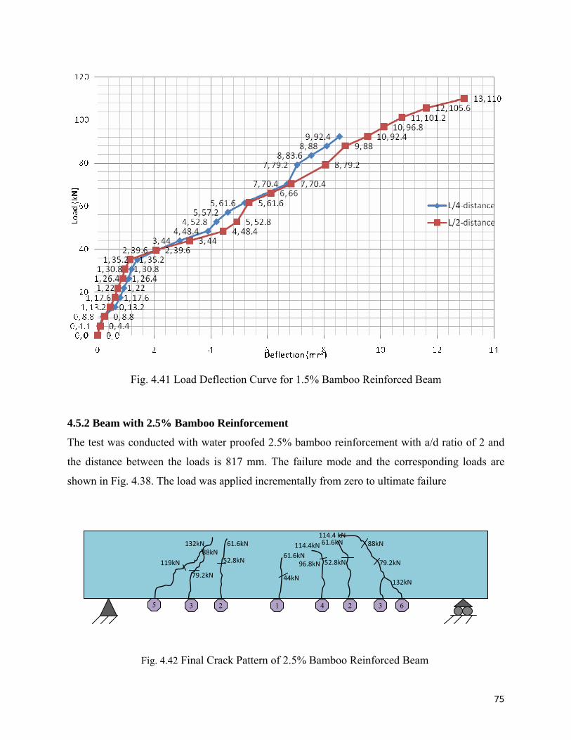
75
Fig. 4.41 Load Deflection Curve for 1.5% Bamboo Reinforced Beam
4.5.2 Beam with 2.5% Bamboo Reinforcement
The test was conducted with water proofed 2.5% bamboo reinforcement with a/d ratio of 2 and
the distance between the loads is 817 mm. The failure mode and the corresponding loads are
shown in Fig. 4.38. The load was applied incrementally from zero to ultimate failure
Fig. 4.42 Final Crack Pattern of 2.5% Bamboo Reinforced Beam
1 22 33 45 6
44kN
61.6kN96.8kN
114.4kN
52.8kN
61.6kN
132kN
79.2kN
88kN114.4 kN
52.8kN
61.6kN
79.2kN
88kN 119kN
132kN
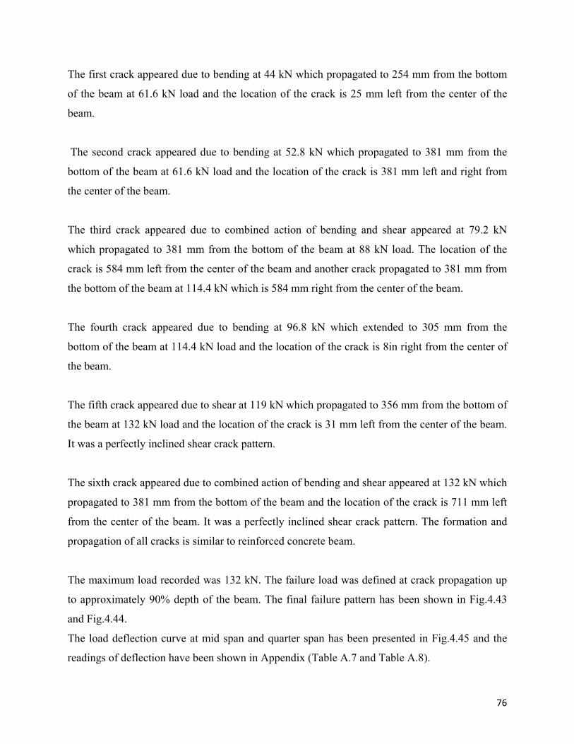
76
The first crack appeared due to bending at 44 kN which propagated to 254 mm from the bottom
of the beam at 61.6 kN load and the location of the crack is 25 mm left from the center of the
beam.
The second crack appeared due to bending at 52.8 kN which propagated to 381 mm from the
bottom of the beam at 61.6 kN load and the location of the crack is 381 mm left and right from
the center of the beam.
The third crack appeared due to combined action of bending and shear appeared at 79.2 kN
which propagated to 381 mm from the bottom of the beam at 88 kN load. The location of the
crack is 584 mm left from the center of the beam and another crack propagated to 381 mm from
the bottom of the beam at 114.4 kN which is 584 mm right from the center of the beam.
The fourth crack appeared due to bending at 96.8 kN which extended to 305 mm from the
bottom of the beam at 114.4 kN load and the location of the crack is 8in right from the center of
the beam.
The fifth crack appeared due to shear at 119 kN which propagated to 356 mm from the bottom of
the beam at 132 kN load and the location of the crack is 31 mm left from the center of the beam.
It was a perfectly inclined shear crack pattern.
The sixth crack appeared due to combined action of bending and shear appeared at 132 kN which
propagated to 381 mm from the bottom of the beam and the location of the crack is 711 mm left
from the center of the beam. It was a perfectly inclined shear crack pattern. The formation and
propagation of all cracks is similar to reinforced concrete beam.
The maximum load recorded was 132 kN. The failure load was defined at crack propagation up
to approximately 90% depth of the beam. The final failure pattern has been shown in Fig.4.43
and Fig.4.44.
The load deflection curve at mid span and quarter span has been presented in Fig.4.45 and the
readings of deflection have been shown in Appendix (Table A.7 and Table A.8).
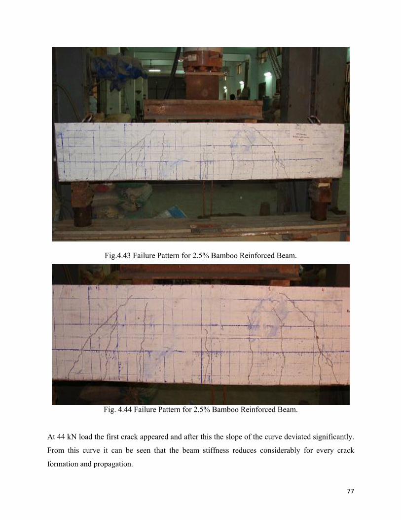
77
Fig.4.43 Failure Pattern for 2.5% Bamboo Reinforced Beam.
Fig. 4.44 Failure Pattern for 2.5% Bamboo Reinforced Beam.
At 44 kN load the first crack appeared and after this the slope of the curve deviated significantly.
From this curve it can be seen that the beam stiffness reduces considerably for every crack
formation and propagation.
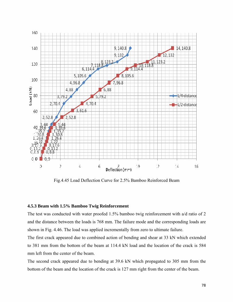
78
Fig.4.45 Load Deflection Curve for 2.5% Bamboo Reinforced Beam
4.5.3 Beam with 1.5% Bamboo Twig Reinforcement
The test was conducted with water proofed 1.5% bamboo twig reinforcement with a/d ratio of 2
and the distance between the loads is 768 mm. The failure mode and the corresponding loads are
shown in Fig. 4.46. The load was applied incrementally from zero to ultimate failure.
The first crack appeared due to combined action of bending and shear at 33 kN which extended
to 381 mm from the bottom of the beam at 114.4 kN load and the location of the crack is 584
mm left from the center of the beam.
The second crack appeared due to bending at 39.6 kN which propagated to 305 mm from the
bottom of the beam and the location of the crack is 127 mm right from the center of the beam.
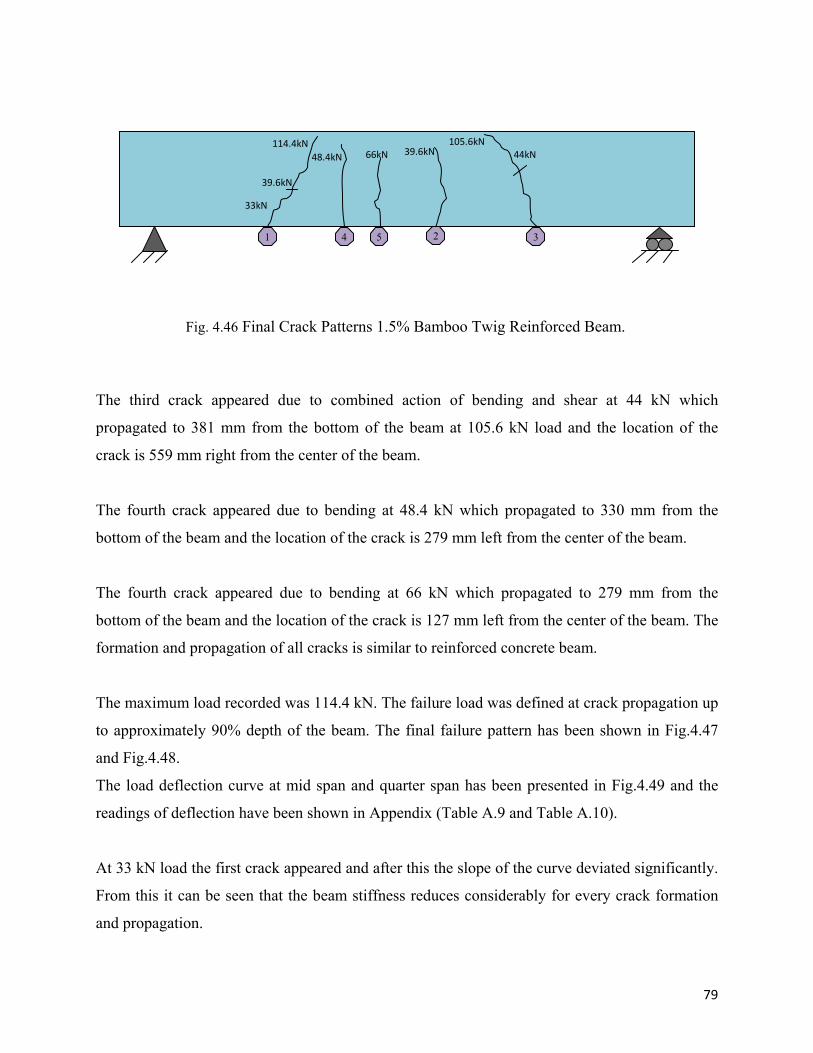
79
The third crack appeared due to combined action of bending and shear at 44 kN which
propagated to 381 mm from the bottom of the beam at 105.6 kN load and the location of the
crack is 559 mm right from the center of the beam.
The fourth crack appeared due to bending at 48.4 kN which propagated to 330 mm from the
bottom of the beam and the location of the crack is 279 mm left from the center of the beam.
The fourth crack appeared due to bending at 66 kN which propagated to 279 mm from the
bottom of the beam and the location of the crack is 127 mm left from the center of the beam. The
formation and propagation of all cracks is similar to reinforced concrete beam.
The maximum load recorded was 114.4 kN. The failure load was defined at crack propagation up
to approximately 90% depth of the beam. The final failure pattern has been shown in Fig.4.47
and Fig.4.48.
The load deflection curve at mid span and quarter span has been presented in Fig.4.49 and the
readings of deflection have been shown in Appendix (Table A.9 and Table A.10).
At 33 kN load the first crack appeared and after this the slope of the curve deviated significantly.
From this it can be seen that the beam stiffness reduces considerably for every crack formation
and propagation.
Fig. 4.46 Final Crack Patterns 1.5% Bamboo Twig Reinforced Beam.
1 4 5 2 3
33kN
39.6kN
114.4kN48.4kN 66kN 39.6kN 44kN
105.6kN
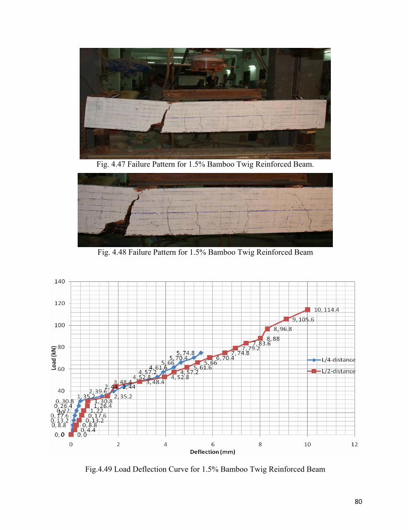
80
Fig. 4.47 Failure Pattern for 1.5% Bamboo Twig Reinforced Beam.
Fig. 4.48 Failure Pattern for 1.5% Bamboo Twig Reinforced Beam
Fig.4.49 Load Deflection Curve for 1.5% Bamboo Twig Reinforced Beam
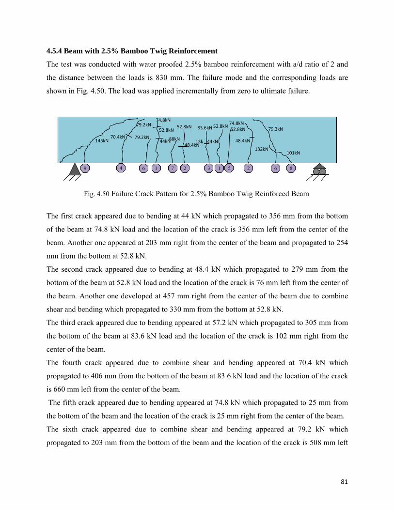
81
4.5.4 Beam with 2.5% Bamboo Twig Reinforcement
The test was conducted with water proofed 2.5% bamboo reinforcement with a/d ratio of 2 and
the distance between the loads is 830 mm. The failure mode and the corresponding loads are
shown in Fig. 4.50. The load was applied incrementally from zero to ultimate failure.
The first crack appeared due to bending at 44 kN which propagated to 356 mm from the bottom
of the beam at 74.8 kN load and the location of the crack is 356 mm left from the center of the
beam. Another one appeared at 203 mm right from the center of the beam and propagated to 254
mm from the bottom at 52.8 kN.
The second crack appeared due to bending at 48.4 kN which propagated to 279 mm from the
bottom of the beam at 52.8 kN load and the location of the crack is 76 mm left from the center of
the beam. Another one developed at 457 mm right from the center of the beam due to combine
shear and bending which propagated to 330 mm from the bottom at 52.8 kN.
The third crack appeared due to bending appeared at 57.2 kN which propagated to 305 mm from
the bottom of the beam at 83.6 kN load and the location of the crack is 102 mm right from the
center of the beam.
The fourth crack appeared due to combine shear and bending appeared at 70.4 kN which
propagated to 406 mm from the bottom of the beam at 83.6 kN load and the location of the crack
is 660 mm left from the center of the beam.
The fifth crack appeared due to bending appeared at 74.8 kN which propagated to 25 mm from
the bottom of the beam and the location of the crack is 25 mm right from the center of the beam.
The sixth crack appeared due to combine shear and bending appeared at 79.2 kN which
propagated to 203 mm from the bottom of the beam and the location of the crack is 508 mm left
Fig. 4.50 Failure Crack Pattern for 2.5% Bamboo Twig Reinforced Beam
9 4 6 1 7 2 3 1 5 2 6 8
145kN 70.4kN
79.2kN
79.2kN44kN
52.8kN
74.8kN
88kN48.4kN
52.8kN
13k
83.6kN
44kN
52.8kN 74.8kN
48.4kN
52.8kN 79.2kN
101kN 132kN
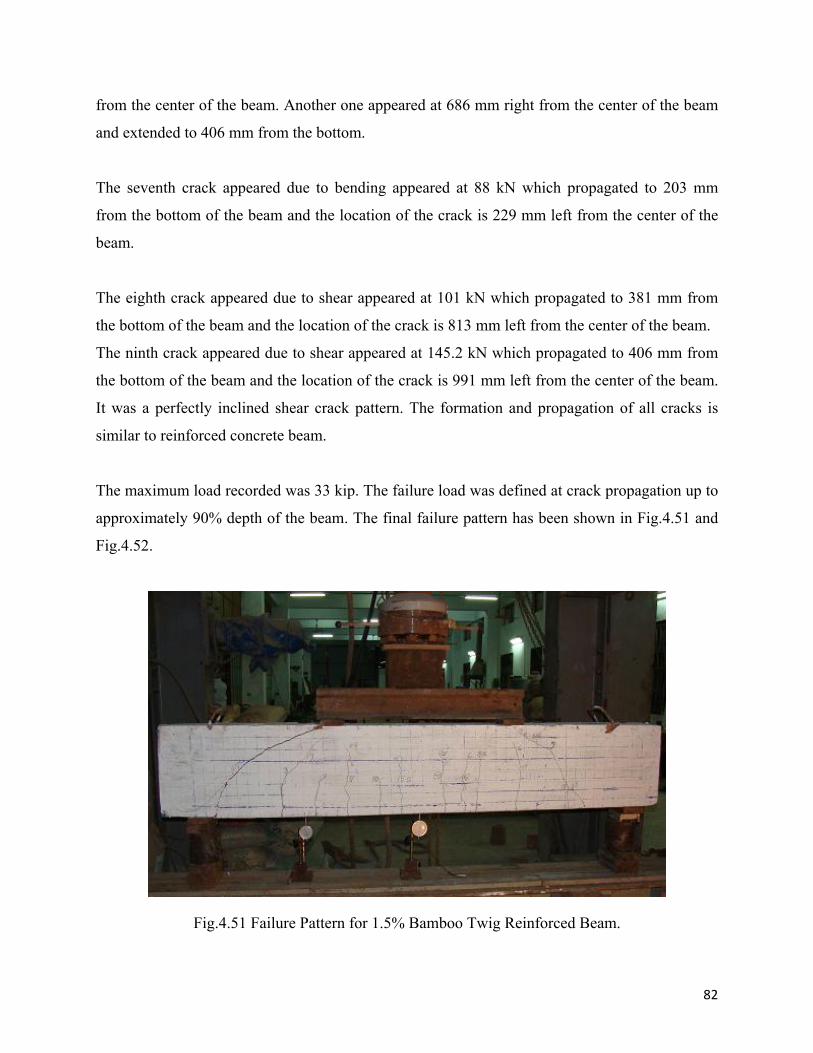
82
from the center of the beam. Another one appeared at 686 mm right from the center of the beam
and extended to 406 mm from the bottom.
The seventh crack appeared due to bending appeared at 88 kN which propagated to 203 mm
from the bottom of the beam and the location of the crack is 229 mm left from the center of the
beam.
The eighth crack appeared due to shear appeared at 101 kN which propagated to 381 mm from
the bottom of the beam and the location of the crack is 813 mm left from the center of the beam.
The ninth crack appeared due to shear appeared at 145.2 kN which propagated to 406 mm from
the bottom of the beam and the location of the crack is 991 mm left from the center of the beam.
It was a perfectly inclined shear crack pattern. The formation and propagation of all cracks is
similar to reinforced concrete beam.
The maximum load recorded was 33 kip. The failure load was defined at crack propagation up to
approximately 90% depth of the beam. The final failure pattern has been shown in Fig.4.51 and
Fig.4.52.
Fig.4.51 Failure Pattern for 1.5% Bamboo Twig Reinforced Beam.
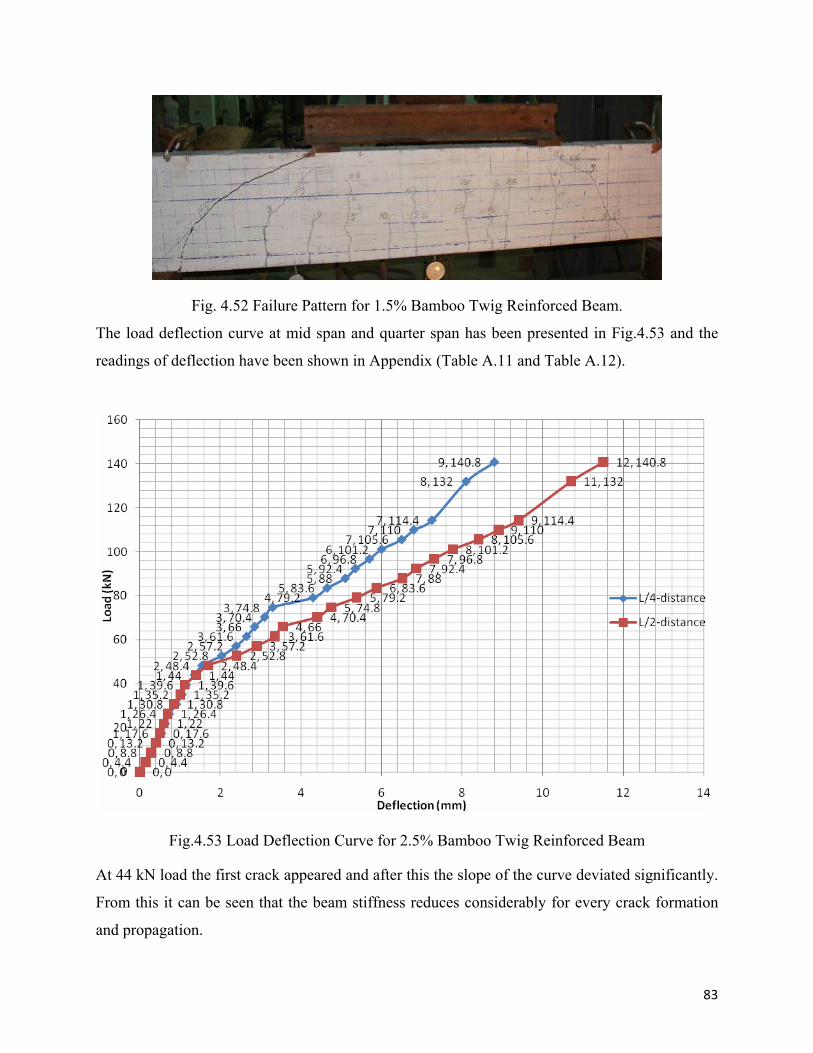
83
Fig. 4.52 Failure Pattern for 1.5% Bamboo Twig Reinforced Beam.
The load deflection curve at mid span and quarter span has been presented in Fig.4.53 and the
readings of deflection have been shown in Appendix (Table A.11 and Table A.12).
Fig.4.53 Load Deflection Curve for 2.5% Bamboo Twig Reinforced Beam
At 44 kN load the first crack appeared and after this the slope of the curve deviated significantly.
From this it can be seen that the beam stiffness reduces considerably for every crack formation
and propagation.
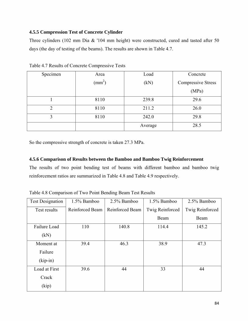
84
4.5.5 Compression Test of Concrete Cylinder
Three cylinders (102 mm Dia & '104 mm height) were constructed, cured and tasted after 50
days (the day of testing of the beams). The results are shown in Table 4.7.
Table 4.7 Results of Concrete Compressive Tests
Specimen Area
(mm2)
Load
(kN)
Concrete
Compressive Stress
(MPa)
1 8110 239.8 29.6
2 8110 211.2 26.0
3 8110 242.0 29.8
Average 28.5
So the compressive strength of concrete is taken 27.3 MPa.
4.5.6 Comparison of Results between the Bamboo and Bamboo Twig Reinforcement
The results of two point bending test of beams with different bamboo and bamboo twig
reinforcement ratios are summarized in Table 4.8 and Table 4.9 respectively.
Table 4.8 Comparison of Two Point Bending Beam Test Results
Test Designation
Test results
1.5% Bamboo
Reinforced Beam
2.5% Bamboo
Reinforced Beam
1.5% Bamboo
Twig Reinforced
Beam
2.5% Bamboo
Twig Reinforced
Beam
Failure Load
(kN)
110 140.8 114.4 145.2
Moment at
Failure
(kip-in)
39.4 46.3 38.9 47.3
Load at First
Crack
(kip)
39.6 44 33 44
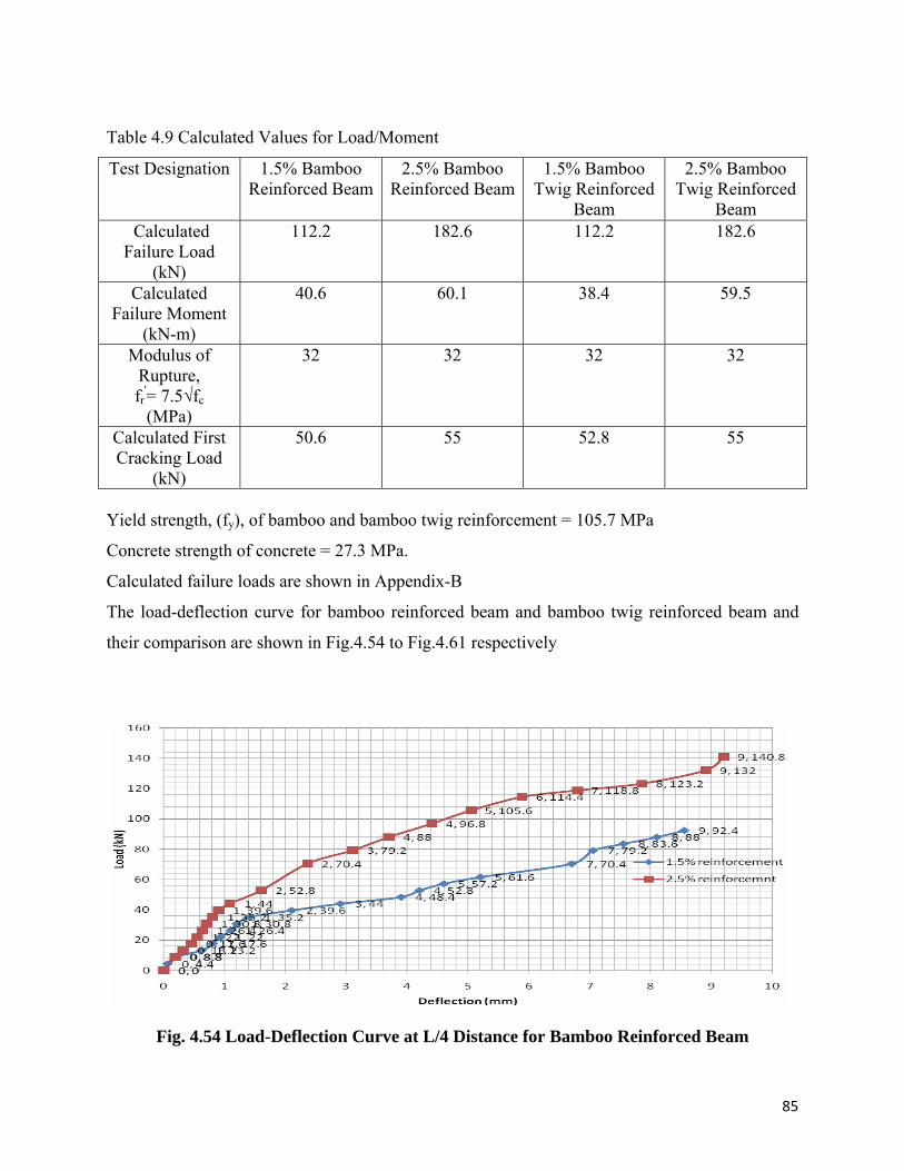
85
Table 4.9 Calculated Values for Load/Moment
Test Designation 1.5% Bamboo Reinforced Beam
2.5% Bamboo Reinforced Beam
1.5% Bamboo Twig Reinforced
Beam
2.5% Bamboo Twig Reinforced
Beam Calculated
Failure Load (kN)
112.2 182.6 112.2 182.6
Calculated Failure Moment
(kN-m)
40.6 60.1 38.4 59.5
Modulus of Rupture, fr
'= 7.5√fc
(MPa)
32 32 32 32
Calculated First Cracking Load
(kN)
50.6 55 52.8 55
Yield strength, (fy), of bamboo and bamboo twig reinforcement = 105.7 MPa
Concrete strength of concrete = 27.3 MPa.
Calculated failure loads are shown in Appendix-B
The load-deflection curve for bamboo reinforced beam and bamboo twig reinforced beam and
their comparison are shown in Fig.4.54 to Fig.4.61 respectively
Fig. 4.54 Load-Deflection Curve at L/4 Distance for Bamboo Reinforced Beam
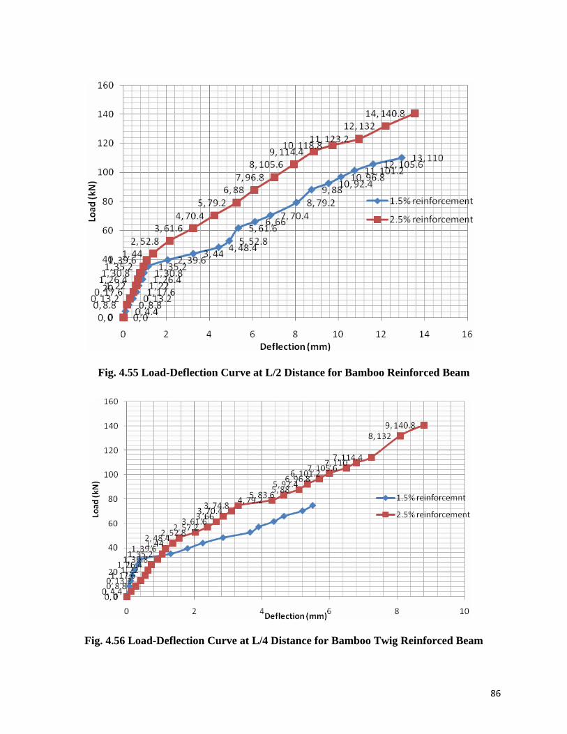
86
Fig. 4.55 Load-Deflection Curve at L/2 Distance for Bamboo Reinforced Beam
Fig. 4.56 Load-Deflection Curve at L/4 Distance for Bamboo Twig Reinforced Beam
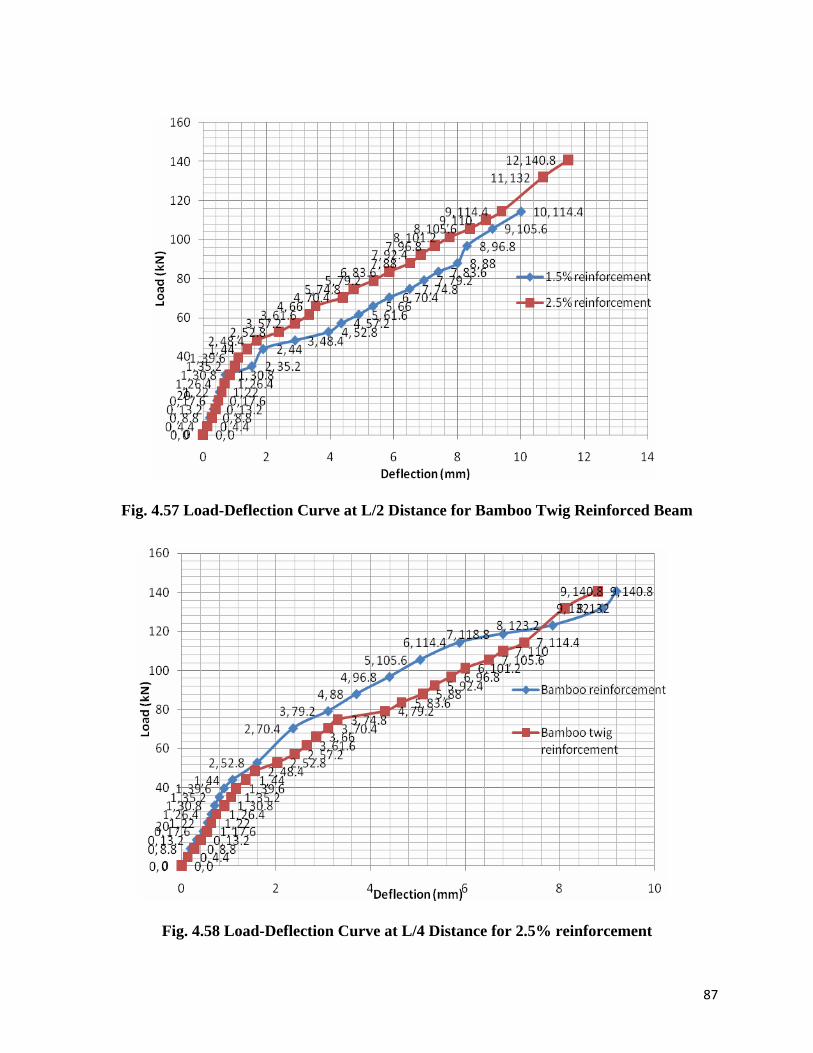
87
Fig. 4.57 Load-Deflection Curve at L/2 Distance for Bamboo Twig Reinforced Beam
Fig. 4.58 Load-Deflection Curve at L/4 Distance for 2.5% reinforcement
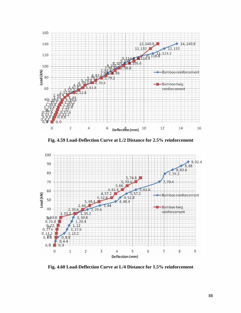
88
Fig. 4.59 Load-Deflection Curve at L/2 Distance for 2.5% reinforcement
Fig. 4.60 Load-Deflection Curve at L/4 Distance for 1.5% reinforcement
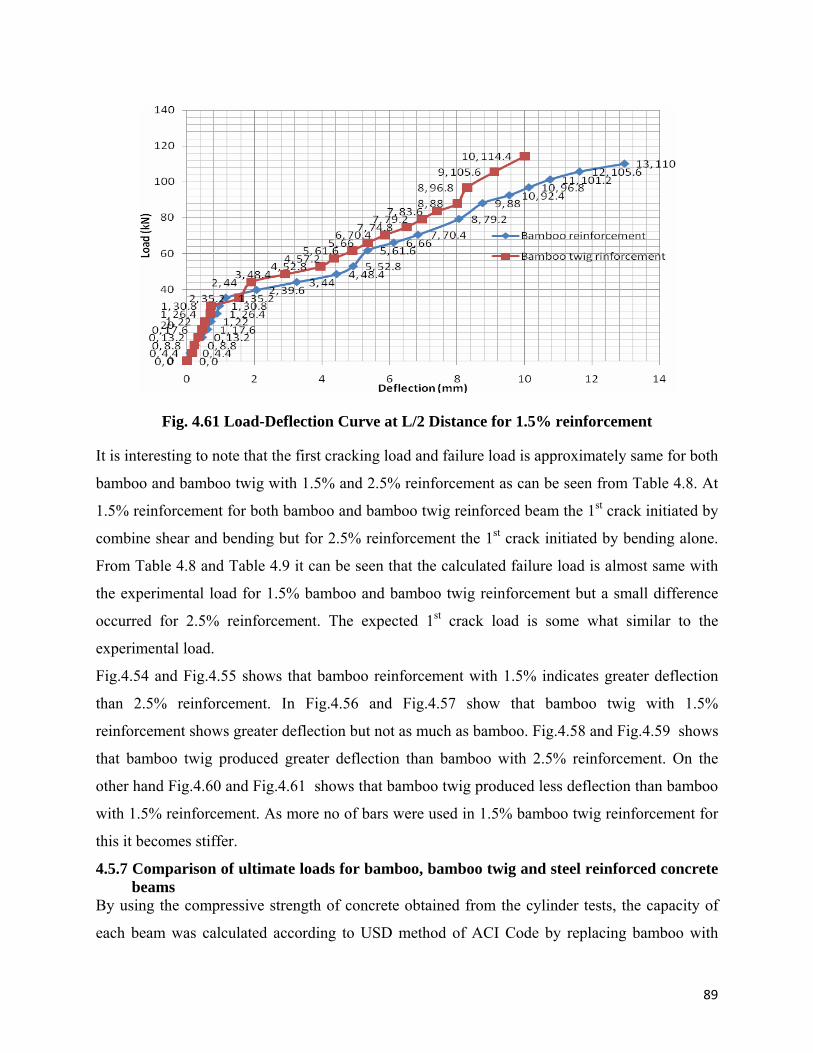
89
Fig. 4.61 Load-Deflection Curve at L/2 Distance for 1.5% reinforcement
It is interesting to note that the first cracking load and failure load is approximately same for both
bamboo and bamboo twig with 1.5% and 2.5% reinforcement as can be seen from Table 4.8. At
1.5% reinforcement for both bamboo and bamboo twig reinforced beam the 1st crack initiated by
combine shear and bending but for 2.5% reinforcement the 1st crack initiated by bending alone.
From Table 4.8 and Table 4.9 it can be seen that the calculated failure load is almost same with
the experimental load for 1.5% bamboo and bamboo twig reinforcement but a small difference
occurred for 2.5% reinforcement. The expected 1st crack load is some what similar to the
experimental load.
Fig.4.54 and Fig.4.55 shows that bamboo reinforcement with 1.5% indicates greater deflection
than 2.5% reinforcement. In Fig.4.56 and Fig.4.57 show that bamboo twig with 1.5%
reinforcement shows greater deflection but not as much as bamboo. Fig.4.58 and Fig.4.59 shows
that bamboo twig produced greater deflection than bamboo with 2.5% reinforcement. On the
other hand Fig.4.60 and Fig.4.61 shows that bamboo twig produced less deflection than bamboo
with 1.5% reinforcement. As more no of bars were used in 1.5% bamboo twig reinforcement for
this it becomes stiffer.
4.5.7 Comparison of ultimate loads for bamboo, bamboo twig and steel reinforced concrete beams
By using the compressive strength of concrete obtained from the cylinder tests, the capacity of
each beam was calculated according to USD method of ACI Code by replacing bamboo with
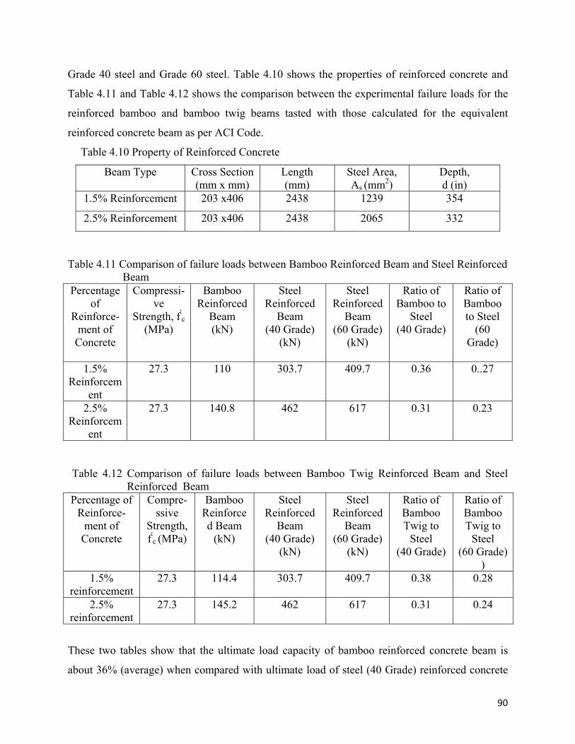
90
Grade 40 steel and Grade 60 steel. Table 4.10 shows the properties of reinforced concrete and
Table 4.11 and Table 4.12 shows the comparison between the experimental failure loads for the
reinforced bamboo and bamboo twig beams tasted with those calculated for the equivalent
reinforced concrete beam as per ACI Code.
Table 4.10 Property of Reinforced Concrete
Beam Type Cross Section (mm x mm)
Length (mm)
Steel Area, As (mm2)
Depth, d (in)
1.5% Reinforcement 203 x406 2438 1239 354
2.5% Reinforcement 203 x406 2438 2065 332
Table 4.11 Comparison of failure loads between Bamboo Reinforced Beam and Steel Reinforced
Beam Percentage
of Reinforce-
ment of Concrete
Compressi-ve
Strength, f'c
(MPa)
Bamboo Reinforced
Beam (kN)
Steel Reinforced
Beam (40 Grade)
(kN)
Steel Reinforced
Beam (60 Grade)
(kN)
Ratio of Bamboo to
Steel (40 Grade)
Ratio of Bamboo to Steel
(60 Grade)
1.5%
Reinforcement
27.3 110 303.7 409.7 0.36 0..27
2.5% Reinforcem
ent
27.3 140.8 462 617 0.31 0.23
Table 4.12 Comparison of failure loads between Bamboo Twig Reinforced Beam and Steel
Reinforced Beam Percentage of
Reinforce-ment of
Concrete
Compre-ssive
Strength, f'
c (MPa)
Bamboo Reinforced Beam
(kN)
Steel Reinforced
Beam (40 Grade)
(kN)
Steel Reinforced
Beam (60 Grade)
(kN)
Ratio of Bamboo Twig to
Steel (40 Grade)
Ratio of Bamboo Twig to
Steel (60 Grade)
) 1.5%
reinforcement 27.3 114.4 303.7 409.7 0.38 0.28
2.5% reinforcement
27.3 145.2 462 617 0.31 0.24
These two tables show that the ultimate load capacity of bamboo reinforced concrete beam is
about 36% (average) when compared with ultimate load of steel (40 Grade) reinforced concrete
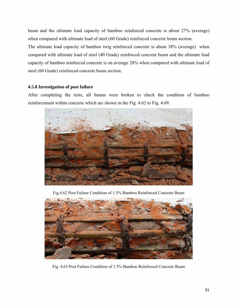
91
beam and the ultimate load capacity of bamboo reinforced concrete is about 27% (average)
when compared with ultimate load of steel (60 Grade) reinforced concrete beam section.
The ultimate load capacity of bamboo twig reinforced concrete is about 38% (average) when
compared with ultimate load of steel (40 Grade) reinforced concrete beam and the ultimate load
capacity of bamboo reinforced concrete is on average 28% when compared with ultimate load of
steel (60 Grade) reinforced concrete beam section.
4.5.8 Investigation of post failure
After completing the tests, all beams were broken to check the condition of bamboo
reinforcement within concrete which are shown in the Fig. 4.62 to Fig. 4.69.
Fig.4.62 Post Failure Condition of 1.5% Bamboo Reinforced Concrete Beam
Fig. 4.63 Post Failure Condition of 1.5% Bamboo Reinforced Concrete Beam
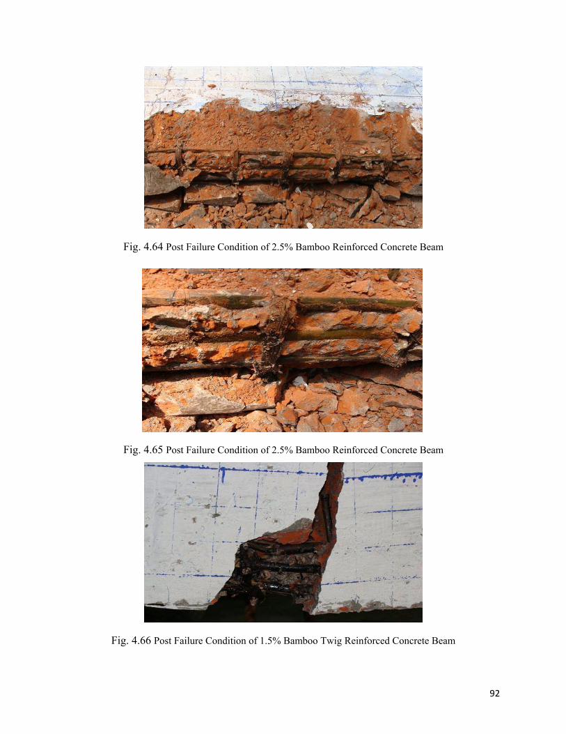
92
Fig. 4.64 Post Failure Condition of 2.5% Bamboo Reinforced Concrete Beam
Fig. 4.65 Post Failure Condition of 2.5% Bamboo Reinforced Concrete Beam
Fig. 4.66 Post Failure Condition of 1.5% Bamboo Twig Reinforced Concrete Beam
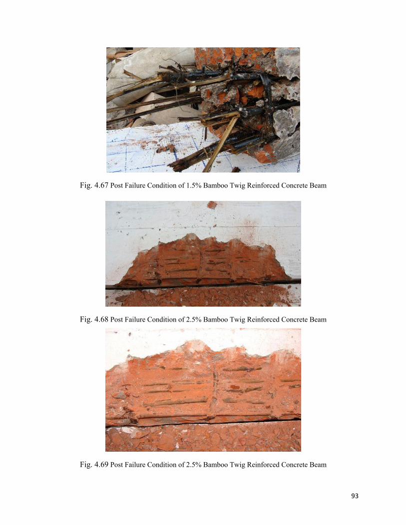
93
Fig. 4.67 Post Failure Condition of 1.5% Bamboo Twig Reinforced Concrete Beam
Fig. 4.68 Post Failure Condition of 2.5% Bamboo Twig Reinforced Concrete Beam
Fig. 4.69 Post Failure Condition of 2.5% Bamboo Twig Reinforced Concrete Beam
94
The reinforcements were in concrete for about 50 days. The condition of both bamboo and
bamboo twigs were found to be in satisfactory condition. From the figures it was seen that the
bamboo and bamboo twigs were in dry condition and no fungus growth was observed. Therefore,
it can be said that the tar coating is effective to inhibit moisture penetration. In most of the cases,
the bond between bamboo and concrete was found to be in good condition. However, after
breaking, some local bond failure (slippage) was observed in some beams.
95
CHAPTER 5
CONCLUSIONS AND RECOMMENDATION FOR FURTHER STUDY
This study has been made to explore the possibility of the use of bamboo and bamboo twig as a
potential reinforcement in concrete structural member (beam). To achieve this objective a series
of tension and pull out tests were conducted on bamboo and bamboo twig followed by two point
bending tests of concrete beams reinforced with bamboo and bamboo twig. The test results of
bamboo reinforced beam were compared with the corresponding steel reinforced concrete beams.
Based on the results obtained from different tests, the following conclusions can be made:
5.1 Tension Tests
(i) If tension tests are conducted without specimen end preparation, actual results may not be
found due to smashing at the grip location specially for bamboo twig specimen but if the
grip is prepared by using GI wire then no smashing and slippage occurs at that location.
Without end preparation, the strength is considerably low because of premature failure at
the grip.
(ii) In general, sample failure was accompanied by failure at knot for twig or tension failure
for bamboo specimens.
(iii) In case of specimens (both bamboo and bamboo twig) with ends wounded by G.I wire,
the tensile strength failure was observed is nearly uniform and their failure pattern is also
similar as splitting parallel to the grain for both bamboo and bamboo twig specimen. The
average tensile strength of bamboo and bamboo twig specimens with prepared ends
(wounded with G.I wire) has been found to be higher than the specimens without
prepared ends. This reduced strength is due to the premature failure at the grip.
(iv) The ultimate strength of bamboo twig is found to be higher than the bamboo specimen.
96
(v) Bamboo specimen shows some nonlinearity before its failure but for bamboo twig
specimen, the stress-strain relation is found to be almost linear up to its failure load.
(vi) The modulus of elasticity, E of bamboo is found to be higher than the bamboo twig
specimen. Therefore, bamboo can sustain higher load than the corresponding bamboo
twig specimen for same strain.
(vii) Knot has been found to be the weak point for bamboo twig specimen when subjected to
tension.
5.2 Pullout Tests
(i) The average bond strength of bamboo specimen decreases when coated with tar but the
bond strength increases significantly when pierced nails are used with coated tar. The
same results were observed for bamboo twig specimen.
(ii) The bamboo and bamboo twig specimens experienced tension failure when pierced nails
are used at the ends.
(iii) The bond strength of bamboo twig is found to be higher than the bamboo specimen in its
natural condition due to the presence of knot.
(iv) When pierced nails are used at the ends, the bond strength of bamboo specimen is found to
be higher than the bamboo twig specimen.
5.3 Bending Test with Two Point Loading
(i) The flexural behaviour of bamboo reinforced concrete beam has been found to be similar
to the concrete beam reinforced with steel.
(ii) The crack patterns of bamboo and bamboo twig reinforced beams are found to be very
similar to the corresponding reinforced concrete beams. The flexural crack initiates
97
vertically near the mid span whereas the shear crack originates near the support at
approximately forty five degree angle.
(iii) With the decrease of reinforcement, the deflection increases for both bamboo and bamboo
twig reinforced beams.
(iv) The ultimate load capacity of bamboo and bamboo twig reinforced beam has been found
to be less than half of ultimate load for corresponding steel reinforced beam.
(v) Bamboo twig reinforced beams carried slightly higher load than the corresponding
bamboo reinforced beams.
(vi) The calculated ultimate load has been found to be very close to the experimental failure
load for both bamboo and bamboo twig reinforced concrete beams. The calculated initial
cracking load has been found to be in close agreement to the experimental load for both
bamboo and bamboo twig reinforced beams.
(vii) Both the tar coated bamboo and bamboo twig reinforcements were found to be in dry
condition in concrete after fifty days and no fungus growth was observed. Therefore, the
use of tar could be very effective as a protective coating.
(viii) Some slippage was observed between concrete and reinforcements (bamboo and bamboo
twig) but overall bonding was found to be satisfactory.
(ix) If the bamboos are soaked in water for two days, it can be easily bend to the desired shape
for shear reinforcement.
5.4 Recommendation for Further Study
The following recommendations may be put forward for future study:
(i) A comprehensive study could be made by involving both experimental and finite element study.
(ii) Cane may be used together with bamboo and bamboo twig reinforcement in concrete beams.
98
(iii) The durability of bamboo and bamboo twig as reinforcement in concrete beams should be investigated.
(iv) Different length of embedment with different surface conditions at the ends of bamboo and bamboo twig in concrete beams could be investigated.
(v) A wide range of bamboo or bamboo twig reinforcement ratio could be considered for further study.
(vi) The possibility of use rice husk ash cement and bamboo in a concrete beam should be explored.
99
REFERENCES
Amada, S., Lchikawa, Y., Munekata, T., Nagase, Y. and Shimizu, H. (1997), “Fiber Texture and
Mechanical Graded Structure of Bamboo”, Composites Part B, Vol.288, pp 13-20.
Amada, S. and Untao, S. (2001), “Fracture Properties of Bamboo”, Composites Part B. Vol. 32,
pp 451-459.
Bamboo in Construction: An Introduction (INBAR 2005) (International Network for Bamboo
and Rattan).
Bamboo structural Design (ISO 1999) (International Standard Organization).
Ghavami, K. (1995), “Ultimate Load Behavior of Bamboo-Reinforced Lightweight Concrete
Beams”, Cement & Concrete Composites, Vol. 17, pp 281-288.
Ghavami, K. (2004),“Bamboo as reinforcement in Structural Concrete Elements”, Cement &
Concrete Composites.
INBAR (2002). (International Network for Bamboo and Rattan) “Bamboo Structure at CO:
Advantages and Desadvantages”, 6 June 2005,
http://www.bwk.tue.nl/bko/research/Bamboo/bamboo.htm.
ISO (1999), “Determination of Physical and Mechanical Properties of Bamboo”, DIS-22157.
(International Standard Organisation).
ISO (1999) (International Standard Organization), “Laboratory Manual on Testing Methods for
Determination of Physical and Mechanical Designing and Building with Bamboo”, TC
165N3315.
Janseen (2000), Designing and Building with Bamboo.
100
Khare, L. (2005), “Performance Evaluation of Bamboo Reinforced Concrete”, M. Sc. Thesis at
The University of Texas At Arlington.
Lo, Cuo, Leung (2004), “The Effect of Fiber Density on Strength Capacity of Bamboo”,
Materials Letter, vol. 58, pp 2595-2598.
Masani (1977), “Studies on Bamboo Concrete Composite Construction”.
Mardjono (1998) Bamboo Knowledge Based Building Design Decision Support System.
Project on Bamboo Structures at the Technical University of Eindhoven INBAR (2002)
(International Network for Bamboo and Rattan).
Steinfeld, C (2001), “A Bamboo Future”, Environmental Design and Construction,
http://www.edcmag.com/CDA/ArticleInformation/features/BNP_Features_Items/, pp1-5.
U.S.Naval Civil Engineering Laboratory (1966,2000), “Bamboo reinforced Concrete
Construction”, http://www.romanconcrete.com/does/bamboo1966/BambooReinforcedConcrete,
pp. 1-19.

101
APPENDIX-A
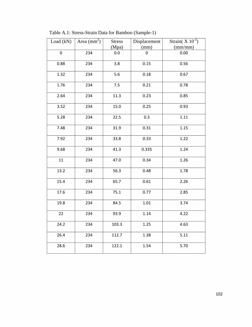
102
Table A.1: Stress-Strain Data for Bamboo (Sample-1)
Load (kN) Area (mm2) Stress (Mpa)
Displacement (mm)
Strain( X 10-3) (mm/mm)
0 234 0.0 0 0.00
0.88 234 3.8 0.15 0.56
1.32 234 5.6 0.18 0.67
1.76 234 7.5 0.21 0.78
2.64 234 11.3 0.23 0.85
3.52 234 15.0 0.25 0.93
5.28 234 22.5 0.3 1.11
7.48 234 31.9 0.31 1.15
7.92 234 33.8 0.33 1.22
9.68 234 41.3 0.335 1.24
11 234 47.0 0.34 1.26
13.2 234 56.3 0.48 1.78
15.4 234 65.7 0.61 2.26
17.6 234 75.1 0.77 2.85
19.8 234 84.5 1.01 3.74
22 234 93.9 1.14 4.22
24.2 234 103.3 1.25 4.63
26.4 234 112.7 1.38 5.11
28.6 234 122.1 1.54 5.70
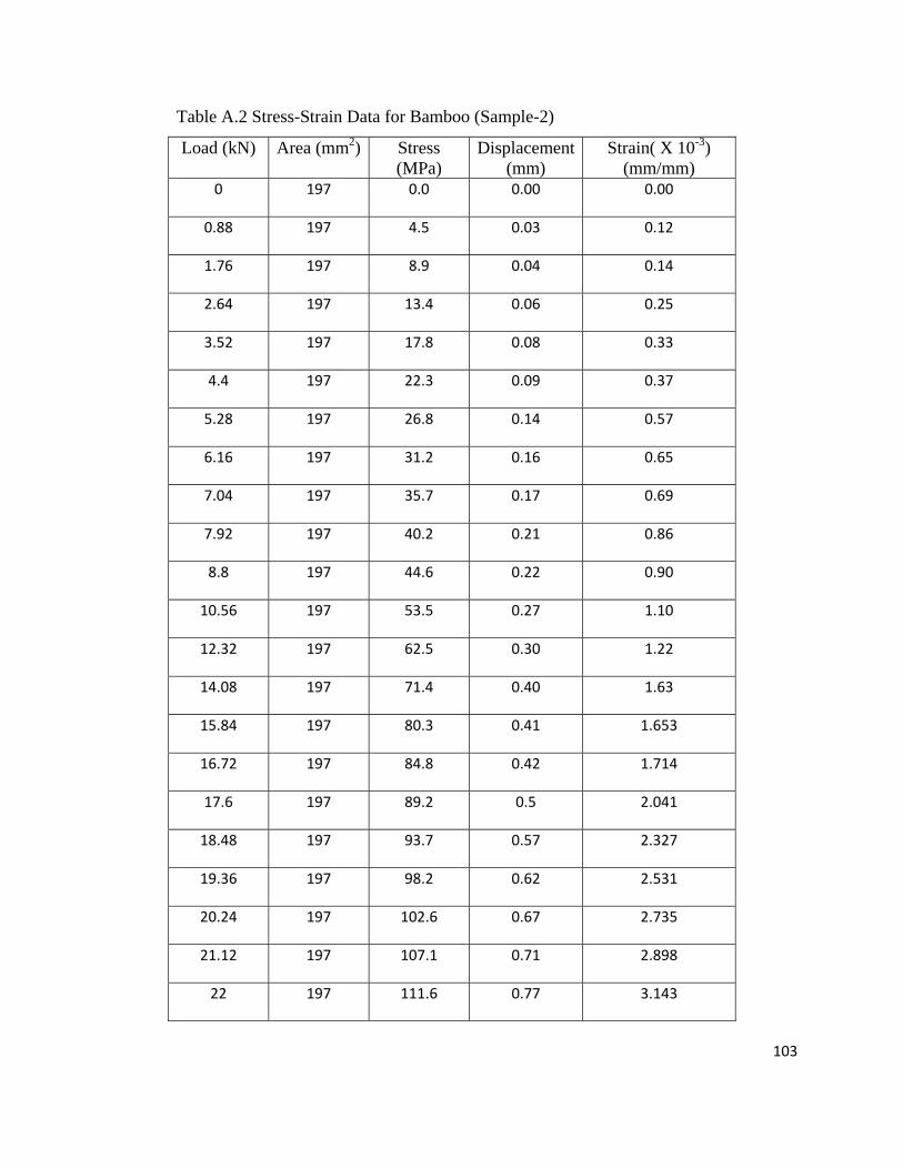
103
Table A.2 Stress-Strain Data for Bamboo (Sample-2)
Load (kN) Area (mm2) Stress (MPa)
Displacement (mm)
Strain( X 10-3) (mm/mm)
0 197 0.0 0.00 0.00
0.88 197 4.5 0.03 0.12
1.76 197 8.9 0.04 0.14
2.64 197 13.4 0.06 0.25
3.52 197 17.8 0.08 0.33
4.4 197 22.3 0.09 0.37
5.28 197 26.8 0.14 0.57
6.16 197 31.2 0.16 0.65
7.04 197 35.7 0.17 0.69
7.92 197 40.2 0.21 0.86
8.8 197 44.6 0.22 0.90
10.56 197 53.5 0.27 1.10
12.32 197 62.5 0.30 1.22
14.08 197 71.4 0.40 1.63
15.84 197 80.3 0.41 1.653
16.72 197 84.8 0.42 1.714
17.6 197 89.2 0.5 2.041
18.48 197 93.7 0.57 2.327
19.36 197 98.2 0.62 2.531
20.24 197 102.6 0.67 2.735
21.12 197 107.1 0.71 2.898
22 197 111.6 0.77 3.143
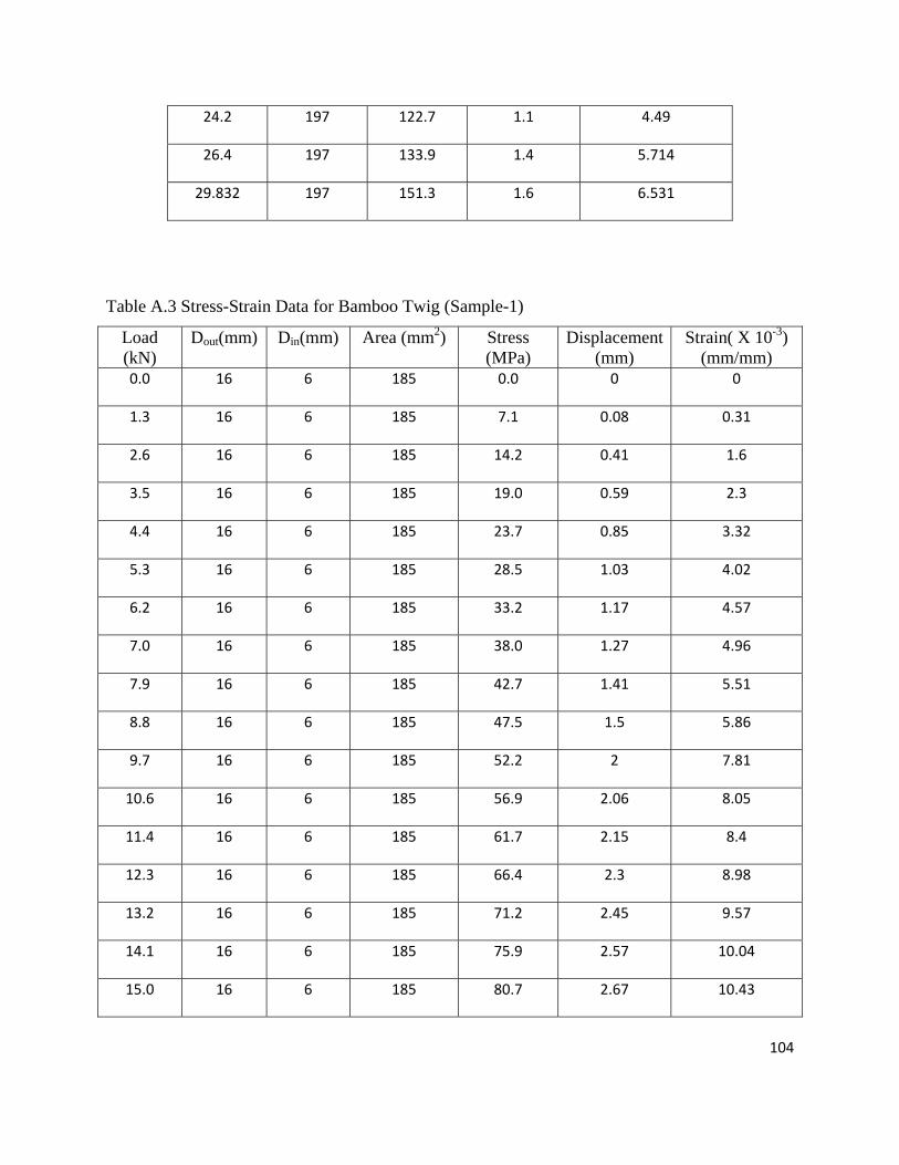
104
24.2 197 122.7 1.1 4.49
26.4 197 133.9 1.4 5.714
29.832 197 151.3 1.6 6.531
Table A.3 Stress-Strain Data for Bamboo Twig (Sample-1)
Load (kN)
Dout(mm) Din(mm) Area (mm2) Stress (MPa)
Displacement (mm)
Strain( X 10-3) (mm/mm)
0.0 16 6 185 0.0 0 0
1.3 16 6 185 7.1 0.08 0.31
2.6 16 6 185 14.2 0.41 1.6
3.5 16 6 185 19.0 0.59 2.3
4.4 16 6 185 23.7 0.85 3.32
5.3 16 6 185 28.5 1.03 4.02
6.2 16 6 185 33.2 1.17 4.57
7.0 16 6 185 38.0 1.27 4.96
7.9 16 6 185 42.7 1.41 5.51
8.8 16 6 185 47.5 1.5 5.86
9.7 16 6 185 52.2 2 7.81
10.6 16 6 185 56.9 2.06 8.05
11.4 16 6 185 61.7 2.15 8.4
12.3 16 6 185 66.4 2.3 8.98
13.2 16 6 185 71.2 2.45 9.57
14.1 16 6 185 75.9 2.57 10.04
15.0 16 6 185 80.7 2.67 10.43
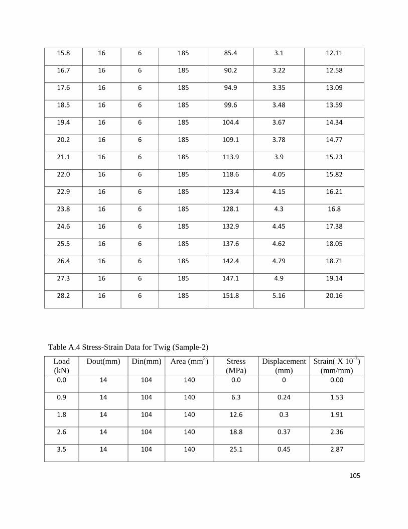
105
15.8 16 6 185 85.4 3.1 12.11
16.7 16 6 185 90.2 3.22 12.58
17.6 16 6 185 94.9 3.35 13.09
18.5 16 6 185 99.6 3.48 13.59
19.4 16 6 185 104.4 3.67 14.34
20.2 16 6 185 109.1 3.78 14.77
21.1 16 6 185 113.9 3.9 15.23
22.0 16 6 185 118.6 4.05 15.82
22.9 16 6 185 123.4 4.15 16.21
23.8 16 6 185 128.1 4.3 16.8
24.6 16 6 185 132.9 4.45 17.38
25.5 16 6 185 137.6 4.62 18.05
26.4 16 6 185 142.4 4.79 18.71
27.3 16 6 185 147.1 4.9 19.14
28.2 16 6 185 151.8 5.16 20.16
Table A.4 Stress-Strain Data for Twig (Sample-2)
Load (kN)
Dout(mm) Din(mm) Area (mm2) Stress (MPa)
Displacement (mm)
Strain( X 10-3) (mm/mm)
0.0 14 104 140 0.0 0 0.00
0.9 14 104 140 6.3 0.24 1.53
1.8 14 104 140 12.6 0.3 1.91
2.6 14 104 140 18.8 0.37 2.36
3.5 14 104 140 25.1 0.45 2.87
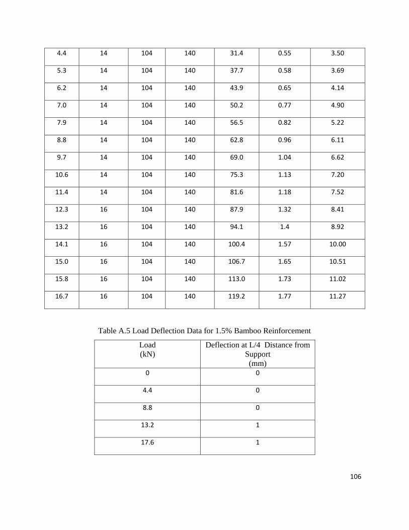
106
4.4 14 104 140 31.4 0.55 3.50
5.3 14 104 140 37.7 0.58 3.69
6.2 14 104 140 43.9 0.65 4.14
7.0 14 104 140 50.2 0.77 4.90
7.9 14 104 140 56.5 0.82 5.22
8.8 14 104 140 62.8 0.96 6.11
9.7 14 104 140 69.0 1.04 6.62
10.6 14 104 140 75.3 1.13 7.20
11.4 14 104 140 81.6 1.18 7.52
12.3 16 104 140 87.9 1.32 8.41
13.2 16 104 140 94.1 1.4 8.92
14.1 16 104 140 100.4 1.57 10.00
15.0 16 104 140 106.7 1.65 10.51
15.8 16 104 140 113.0 1.73 11.02
16.7 16 104 140 119.2 1.77 11.27
Table A.5 Load Deflection Data for 1.5% Bamboo Reinforcement
Load (kN)
Deflection at L/4 Distance from Support (mm)
0 0
4.4 0
8.8 0
13.2 1
17.6 1
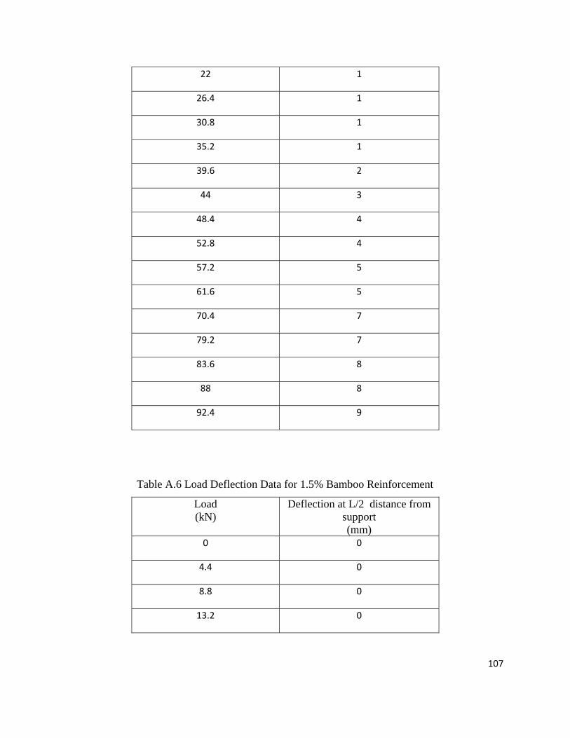
107
22 1
26.4 1
30.8 1
35.2 1
39.6 2
44 3
48.4 4
52.8 4
57.2 5
61.6 5
70.4 7
79.2 7
83.6 8
88 8
92.4 9
Table A.6 Load Deflection Data for 1.5% Bamboo Reinforcement
Load (kN)
Deflection at L/2 distance from support (mm)
0 0
4.4 0
8.8 0
13.2 0
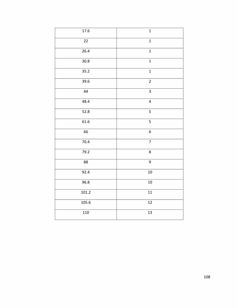
108
17.6 1
22 1
26.4 1
30.8 1
35.2 1
39.6 2
44 3
48.4 4
52.8 5
61.6 5
66 6
70.4 7
79.2 8
88 9
92.4 10
96.8 10
101.2 11
105.6 12
110 13
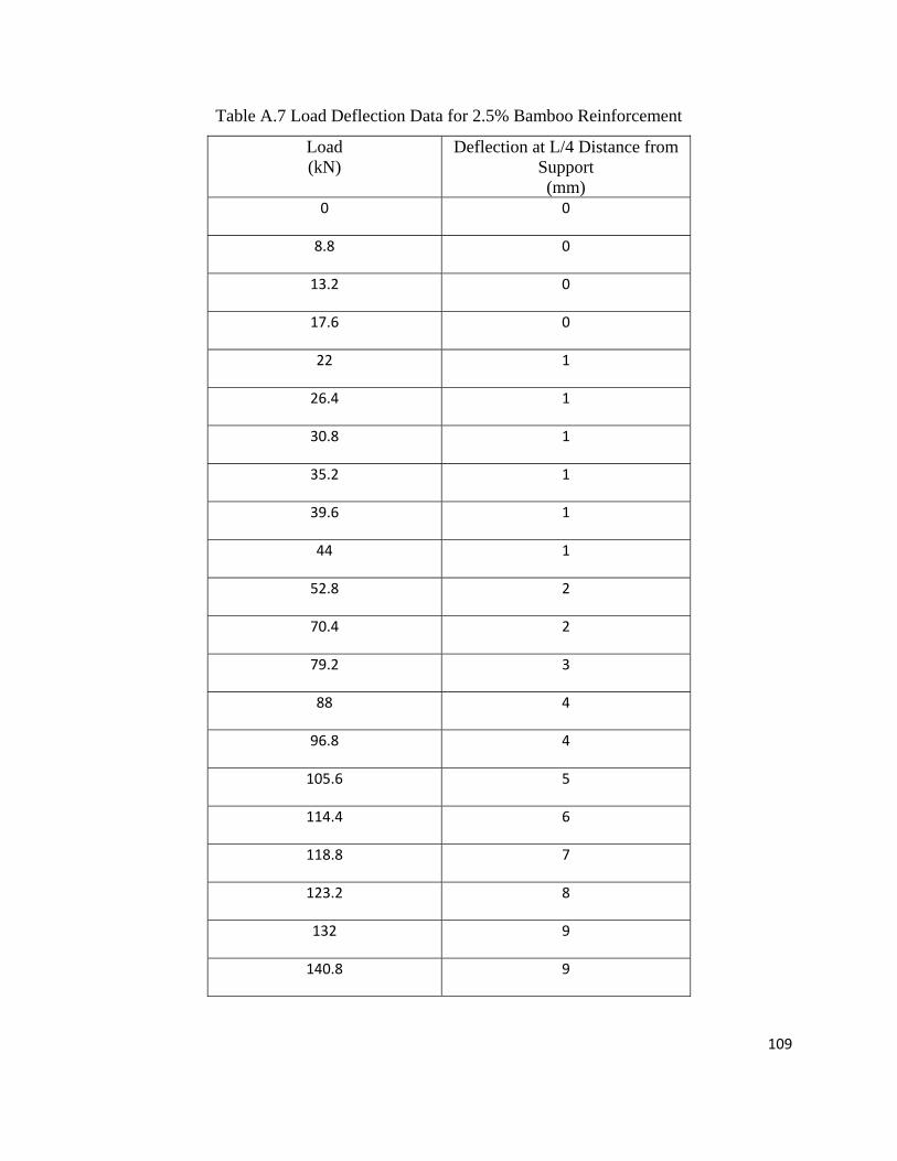
109
Table A.7 Load Deflection Data for 2.5% Bamboo Reinforcement
Load (kN)
Deflection at L/4 Distance from Support (mm)
0 0
8.8 0
13.2 0
17.6 0
22 1
26.4 1
30.8 1
35.2 1
39.6 1
44 1
52.8 2
70.4 2
79.2 3
88 4
96.8 4
105.6 5
114.4 6
118.8 7
123.2 8
132 9
140.8 9
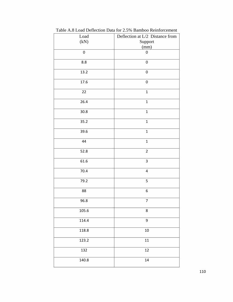
110
Table A.8 Load Deflection Data for 2.5% Bamboo Reinforcement Load (kN)
Deflection at L/2 Distance from Support (mm)
0 0
8.8 0
13.2 0
17.6 0
22 1
26.4 1
30.8 1
35.2 1
39.6 1
44 1
52.8 2
61.6 3
70.4 4
79.2 5
88 6
96.8 7
105.6 8
114.4 9
118.8 10
123.2 11
132 12
140.8 14
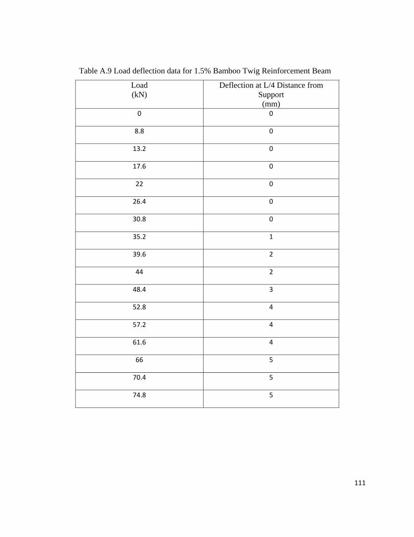
111
Table A.9 Load deflection data for 1.5% Bamboo Twig Reinforcement Beam
Load (kN)
Deflection at L/4 Distance from Support (mm)
0 0
8.8 0
13.2 0
17.6 0
22 0
26.4 0
30.8 0
35.2 1
39.6 2
44 2
48.4 3
52.8 4
57.2 4
61.6 4
66 5
70.4 5
74.8 5
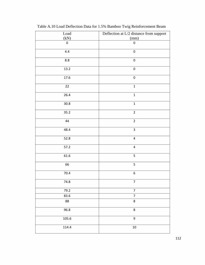
112
Table A.10 Load Deflection Data for 1.5% Bamboo Twig Reinforcement Beam
Load (kN)
Deflection at L/2 distance from support (mm)
0 0
4.4 0
8.8 0
13.2 0
17.6 0
22 1
26.4 1
30.8 1
35.2 2
44 2
48.4 3
52.8 4
57.2 4
61.6 5
66 5
70.4 6
74.8 7
79.2 7
83.6 7
88 8
96.8 8
105.6 9
114.4 10
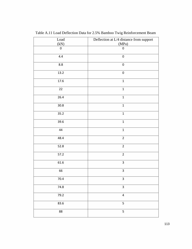
113
Table A.11 Load Deflection Data for 2.5% Bamboo Twig Reinforcement Beam
Load (kN)
Deflection at L/4 distance from support (MPa)
0 0
4.4 0
8.8 0
13.2 0
17.6 1
22 1
26.4 1
30.8 1
35.2 1
39.6 1
44 1
48.4 2
52.8 2
57.2 2
61.6 3
66 3
70.4 3
74.8 3
79.2 4
83.6 5
88 5
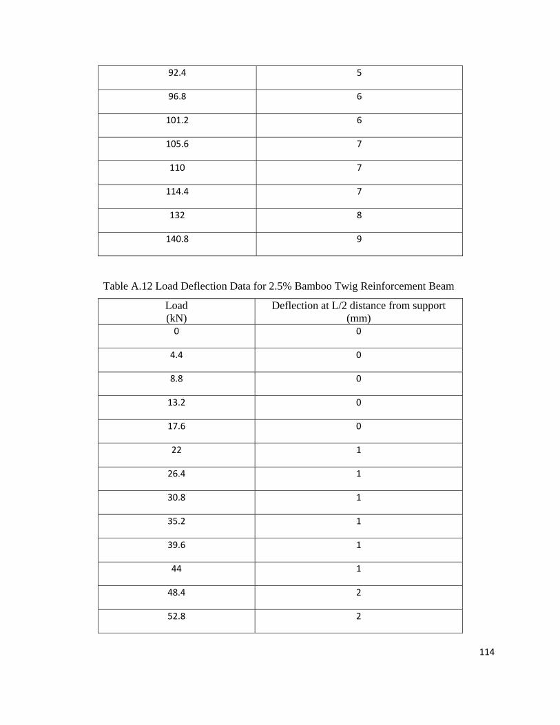
114
92.4 5
96.8 6
101.2 6
105.6 7
110 7
114.4 7
132 8
140.8 9
Table A.12 Load Deflection Data for 2.5% Bamboo Twig Reinforcement Beam
Load (kN)
Deflection at L/2 distance from support (mm)
0 0
4.4 0
8.8 0
13.2 0
17.6 0
22 1
26.4 1
30.8 1
35.2 1
39.6 1
44 1
48.4 2
52.8 2
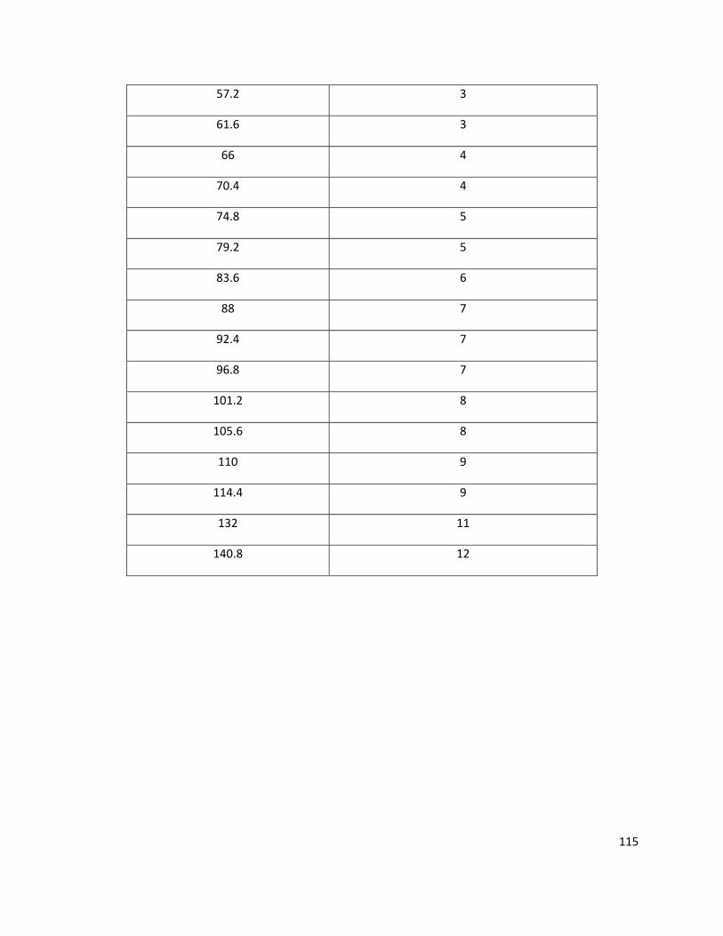
115
57.2 3
61.6 3
66 4
70.4 4
74.8 5
79.2 5
83.6 6
88 7
92.4 7
96.8 7
101.2 8
105.6 8
110 9
114.4 9
132 11
140.8 12

116
APPENDIX-B
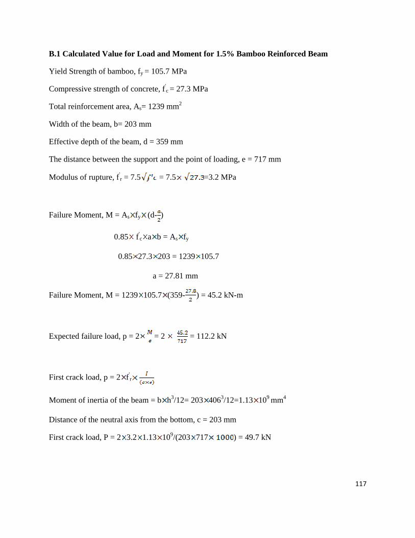
117
B.1 Calculated Value for Load and Moment for 1.5% Bamboo Reinforced Beam
Yield Strength of bamboo, fy = 105.7 MPa
Compressive strength of concrete, f'c = 27.3 MPa
Total reinforcement area, As= 1239 mm2
Width of the beam, b= 203 mm
Effective depth of the beam, d = 359 mm
The distance between the support and the point of loading, e = 717 mm
Modulus of rupture, f'r = 7.5 = 7.5 =3.2 MPa
Failure Moment, M = As fy (d- )
0.85 f'c a b = As fy
0.85 27.3 203 = 1239 105.7
a = 27.81 mm
Failure Moment, M = 1239 105.7 (359- ) = 45.2 kN-m
Expected failure load, p = 2 = 2 = 112.2 kN
First crack load, p = 2 f'r
Moment of inertia of the beam = b h3/12= 203 4063/12=1.13 109 mm4
Distance of the neutral axis from the bottom, c = 203 mm
First crack load, P = 2 3.2 1.13 109/(203 717 ) = 49.7 kN

118
B.2 Calculated Value for Load and Moment for 2.5% Bamboo Reinforced Beam
Yield Strength of bamboo, fy = 105.7 MPa
Compressive strength of concrete, f'c = 27.3 MPa
Total reinforcement area, As= 2060 mm2
Width of the beam, b= 203 mm
Effective depth of the beam, d = 329 mm
The distance between the support and the point of loading, e = 658 mm
Modulus of rupture, f'r = 7.5 = 7.5 =3.2 MPa
Failure Moment, M = As fy (d- )
0.85 f'c a b = As fy
0.85 27.3 203 = 2060 105.7
a = 46.22 mm
Failure Moment, M = 2060 105.7 (329- ) = 66.6 kN-m
Expected failure load, p = 2 = 2 = 112.2 kN
First crack load, p = 2 f'r
Moment of inertia of the beam = b h3/12= 203 4063/12=1.13 109 mm4
Distance of the neutral axis from the bottom, c = 203 mm
First crack load, P = 2 3.2 1.13 109/(203 658 ) = 54.1 kN.
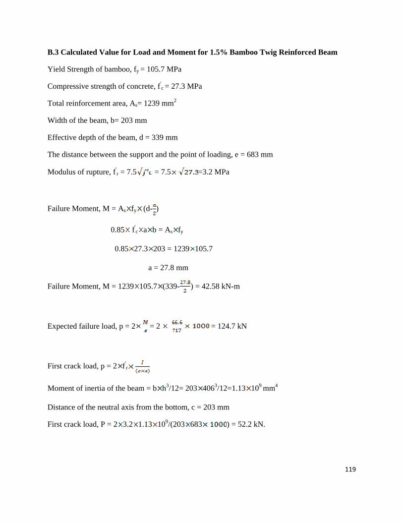
119
B.3 Calculated Value for Load and Moment for 1.5% Bamboo Twig Reinforced Beam
Yield Strength of bamboo, fy = 105.7 MPa
Compressive strength of concrete, f'c = 27.3 MPa
Total reinforcement area, As= 1239 mm2
Width of the beam, b= 203 mm
Effective depth of the beam, d = 339 mm
The distance between the support and the point of loading, e = 683 mm
Modulus of rupture, f'r = 7.5 = 7.5 =3.2 MPa
Failure Moment, M = As fy (d- )
0.85 f'c a b = As fy
0.85 27.3 203 = 1239 105.7
a = 27.8 mm
Failure Moment, M = 1239 105.7 (339- ) = 42.58 kN-m
Expected failure load, p = 2 = 2 = 124.7 kN
First crack load, p = 2 f'r
Moment of inertia of the beam = b h3/12= 203 4063/12=1.13 109 mm4
Distance of the neutral axis from the bottom, c = 203 mm
First crack load, P = 2 3.2 1.13 109/(203 683 ) = 52.2 kN.
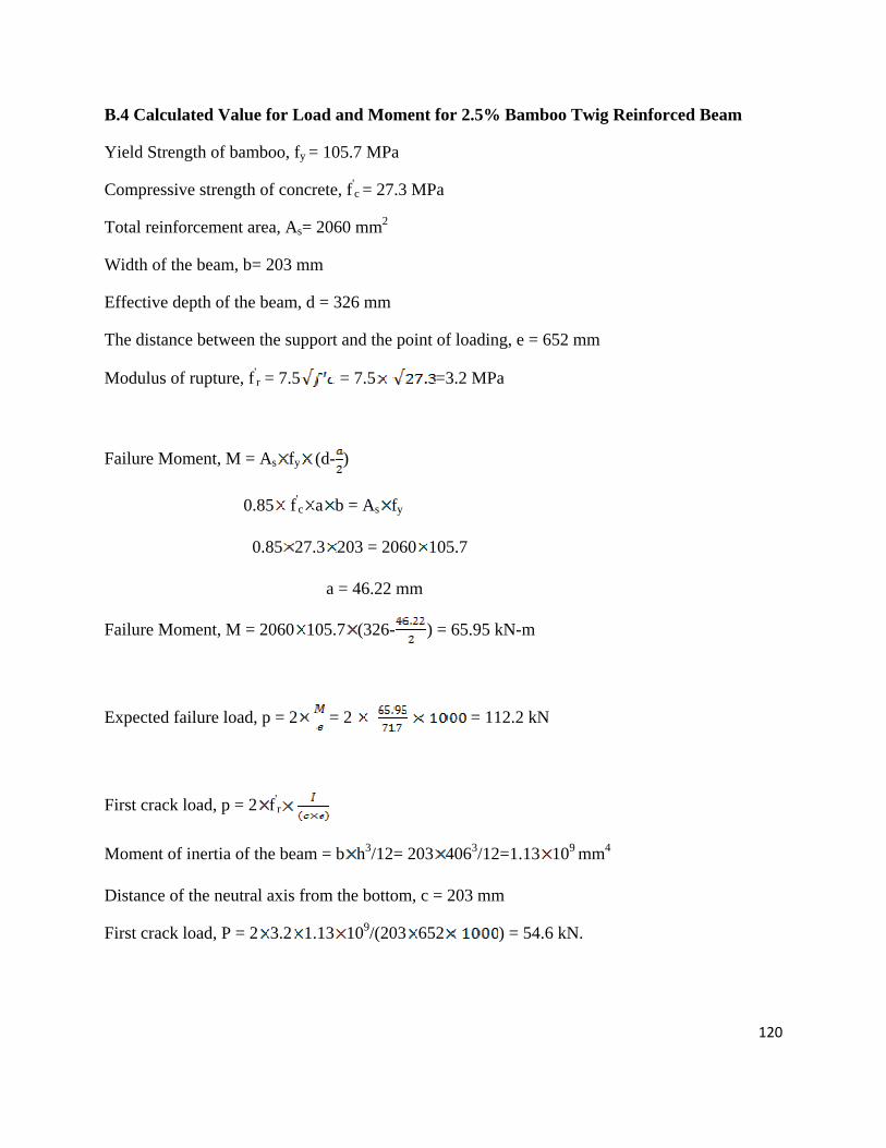
120
B.4 Calculated Value for Load and Moment for 2.5% Bamboo Twig Reinforced Beam
Yield Strength of bamboo, fy = 105.7 MPa
Compressive strength of concrete, f'c = 27.3 MPa
Total reinforcement area, As= 2060 mm2
Width of the beam, b= 203 mm
Effective depth of the beam, d = 326 mm
The distance between the support and the point of loading, e = 652 mm
Modulus of rupture, f'r = 7.5 = 7.5 =3.2 MPa
Failure Moment, M = As fy (d- )
0.85 f'c a b = As fy
0.85 27.3 203 = 2060 105.7
a = 46.22 mm
Failure Moment, M = 2060 105.7 (326- ) = 65.95 kN-m
Expected failure load, p = 2 = 2 = 112.2 kN
First crack load, p = 2 f'r
Moment of inertia of the beam = b h3/12= 203 4063/12=1.13 109 mm4
Distance of the neutral axis from the bottom, c = 203 mm
First crack load, P = 2 3.2 1.13 109/(203 652 ) = 54.6 kN.
![Performance and Durability Evaluation of Bamboo Reinforced ... · ... bamboo reinforced beam [4]. Bamboo reinforced concrete design is similar to steel reinforced concrete design](https://img.pdfslide.net/doc/110x75/5b573ef17f8b9adf7d8d8ed2/performance-and-durability-evaluation-of-bamboo-reinforced-bamboo-reinforced.jpg)