Embed Size (px)
Citation preview

Thomas, B.G. and P. Vanka; “Study of Transient Flow Structures in the Continuous Casting of Steel”, 2000
NSF Design & Manufacturing Grantees Conference, Vancouver, Canada, Jan. 5-8 2000, 14p.
1
Study of Transient Flow Structures in the Continuous Casting of Steel
B.G. Thomas and S.P. Vanka
University of Illinois at Urbana-Champaign
Mechanical and Industrial Engineering.
1206 West Green Street, Urbana, IL 61801
Ph: 217-333-6919, 217-244-8388; Fax: 217-244-6534;
Email: [email protected], [email protected]
Abstract: In continuous casting of steel,
plant observations have found that many
serious quality problems are directly
associated with the flow pattern in the mold.
Previous studies have generated
understanding mainly through numerical
simulations using time-averaged turbulence
models. However, many problems are
intermittent and the essential transient
nature of the flow may be important to their
formation. To obtain further understanding
of these important transient turbulence
processes, this project aims to directly
compute the evolution and dynamics of the
large scale turbulence structures. Accurate
numerical schemes and parallel computers
are being applied to solve the governing
fluid flow equations using a Large-Eddy
Simulation (LES) approach. Computations
are also performed using traditional K-εmodels in order to evaluate their accuracy
and to examine more cases. The ultimate
goal is to generate deeper understanding of
how costly defects form and to find
improvements in design and operating
conditions in continuous casting that can
avoid them.
Introduction: Continuous casting is the
predominant way by which steel is
produced in the world. Continued viability
of the high-volume-low-profit-margin steel
industry depends upon improved efficiency
and consistent quality of the steel
production.1 Plant observations have found
that many serious quality problems are
directly associated with the flow pattern in
the mold [1]. Defects caused by non-
optimal fluid flow are even more important
to the nearer-net-shape thin-slab casting
processes, which are starting to transform
the industry [2]. Some understanding of
this flow region can be obtained through
numerical simulations which use time-
averaged turbulence models. The next step
to obtain more reliable predictions of this
transient turbulence process is to directly
compute the evolution and dynamics of the
large-scale turbulence structures. The
current research is concerned with such
computations, using accurate numerical
schemes and parallel computers to solve the
governing fluid flow equations.
A schematic of part of the continuous
casting process is depicted in Figure 1.
Steel flows through the “tundish,” and then
it exits down through a ceramic Submerged
Entry Nozzle (SEN) and into the mold.
Here, the steel freezes against the water-
cooled copper walls to form a solid shell,
which is continuously withdrawn from the
1 Today, US produces around 80 million
tons of steel per year. The net cost per ton
of scrapping is about $100 per ton. Even if
a fraction of one percent of scrap is avoided
due to improving the process, the savings is
still significant.

Tundish
Submerged Entry Nozzle(SEN)
Meniscus
Copper Mold
Slide Gate(flow control)
Submergence Depth
Liquid SteelPool
Liquid Steel
Protective slag layer
Liquid Mold Flux
Solid Mold Powder
Solidifying Steel Shell
Continuous Withdrawal
Schematic of continuous casting tundish, SEN, and mold
Port Thickness
Port HeightPort Angle
Nozzle Bore
OR:
Stopper Rod(flow control)
Either:
Tundish Well(SEN inlet)
Figure 1. Schematic of tundish and mold region of continuous casting process
2

3
bottom of the mold at a “casting speed” that
matches the flow of the incoming metal. The
primary reason for submerging the nozzle is to
protect the molten steel from re-oxidation as
the steel is delivered from the tundish to the
mold. Argon gas is injected into the nozzle to
help prevent clogging with alumina inclusion
deposits. The submerged nozzle also has an
important influence on steel quality through its
effect on the flow pattern in the mold. The
nozzle should deliver steel uniformly into the
mold while preventing problems such as
surface waves, meniscus freezing, and crack
formation.
Unsteady flow features play an important role
in the continuous casting of steel, yet have
received relatively little attention. In recent
years, with the development of fast computers,
it has become possible to significantly improve
turbulent flow predictions by resolving the
large scales of transient and turbulent flows [3-
4]. These simulations, known as Large-Eddy
Simulations (LES) lie in-between the
approaches of Direct Numerical Simulations
(DNS) and the Reynolds-averaged approach.
In LES, the dominant, energy containing
scales of motion are accurately resolved and
the small scales are modeled. The premise of
LES is that the small scales of turbulent
motion are nearly isotropic and universal
across different flows. Therefore, the effects
of the small scales can be modeled relatively
more accurately compared to modeling all the
scales by a single model. In recent years, LES
has been successfully applied to several flows.
In the present paper, we discuss some recent
results of flow and heat transfer for four
different parts of this project:
1) Two-phase flow in tundish nozzles
2) Unsteady flow in the mold region
3) Fluid flow and heat transfer in mold
4) Heat transfer in the impingement region
Technical Approach: Two different
computational models of fluid flow are used in
this work.
Firstly, the Reynolds-averaged approach was
used to simulate the three-dimensional time-
averaged two-phase flow and heat transfer
fields in both the nozzle and mold regions.
These models were developed using the K-εturbulence model in the commercial package
CFX.
Secondly, Large-Eddy Simulation models of
transient flow in the mold and impinging
regions have been developed. This computer
program, LES3D, integrates the three-
dimensional unsteady incompressible Navier-
Stokes equations using an explicit fractional
step algorithm. Further, in order to take full
advantage of parallel computers, the algorithm
has been implemented with a general domain
decomposition strategy. Each sub-domain of
the flow can be calculated separately on an
individual processor with data interfacing at
the sub-domain boundaries. Advantage is
taken of the Message Passing Interface (MPI)
standards to ensure portability across a variety
of parallel computers, including shared and
distributed memory machines.
In conjunction with the proposed modeling
work, experiments are performed to measure
the flow fields in water models, as well as in
an operating steel caster. In addition to
providing additional insight into the flow
phenomena, these experiments are even more
important to validate the mathematical models,
so that subsequent parametric studies can be
calculated with confidence. Measurements on
both physical water models and in operating
continuous casting in the plant have been
obtained at several of the co-sponsoring steel
companies, including Armco, Inc., and LTV
Steel.

4
Results: The current results from this study
are presented in the following four sections.
Two-Phase Flow in Tundish Nozzles:The tundish nozzle has an important influence
on steel quality through its effect on the flow
pattern in the mold. Argon is commonly
injected into the tundish nozzle to avoid nozzle
clogging. It also affects casting operation and
product quality by changing the flow pattern in
the nozzle and mold. In this part of the project,
a three-dimensional finite difference model is
being applied to model the multi-phase,
steady-state turbulent flow in continuous
casting tundish nozzles under a wide range of
geometries and conditions.
To validate the model, flow fields near the
nozzle port outlets were measured with PIV
(Particle Image Velocimetry) in a 0.4-scale
water model at LTV Steel at Cleveland Ohio.
These velocities were compared with
predictions from the steady-state turbulent
flow model. Reasonable agreement was
achieved, as shown in the example given in
Figure 2. Extensive parametric studies using
the validated model have been performed to
investigate the effects of many different
variables on the flow pattern. These variables
include the process variables (such as casting
speed, tundish liquid level, slide-gate opening
and orientation), argon injection parameters
(such as gas injection flow rate, bubble size,
gas injection area and locations), and the
geometric parameters of the nozzle (such as
the port angle, port height, port width, bottom
shape).
The numerical modeling results were
converted into trends that correspond with
real-life operating conditions, where several
variables change simultaneously. To achieve
this, an advanced multivariable curve-fitting
model has been developed. For example,
Figure 3 shows how the lowest pressure in the
nozzle changes with the casting speed
assuming variable gate opening under the
standard operating conditions of fixed tundish
liquid level and fixed argon injection rate. It
can be seen that detrimental negative pressure
is obtained at low casting speeds (below about
1 m/min for this nozzle, depending on tundish
depth). Thus, smaller nozzle bores should be
used for low casting speeds. During ladle
exchanges, casting speed should only be
slowed down if the tundish level is also
lowered. Results such as these should help
design standard operating conditions that
minimize defects, such as the inclusions
created when air aspiration occurs while
operating at negative nozzle pressure.
Unsteady flow in the mold region:Transient flow phenomena in the mold may be
very important to the generation of quality
problems, such as surface level fluctuations,
inclusion and bubble entrainment. To study
these phenomena, a large-eddy simulation
model is being developed. This model is being
validated using PIV (Particle Image
Velocimetry) measurements, done on a 0.4-
scale water model of the mold (at LTV Steel,
Cleveland, Ohio.
The LES model currently involves the
following simplifications. Firstly, the inlet to
the mold is approximated as fully-developed
turbulent flow from a square duct, assuming
that the actual profile at the inlet of the water
model dissipates a short distance from the
inlet, thereby not affecting the flow features in
the mold significantly. Secondly, the top
surface is approximated as a free slip boundary
instead of the free surface that is present in the
water model. This is justified as level
fluctuations are found to be insignificant and
the surface profile is almost flat.
Examples of the comparative study are given
in Figure 4 (instantaneous) and Figure 5 (time
averaged). The major findings of this
comparative study are as follows.

1 m/s
z,w
x,u
PredictedMeasured
Slicejet angle:
Predicted: 46.0° downMeasured: 44.1° down
(a) PIV measurement of flow field near the nozzle port (center plane)
(c) Two-phase model prediction(CFX)
(b) Velocity profile and average slice jet angle at the nozzle port
Figure 2 Comparison of prediction from the two-phase modle(CFX) with PIV measurements at the center plane of the nozzle port (Case A5: Qliq = 14.2 gal/min, Qgas = 1 scfh)
00.10.20.30.40.50.60.70.80
5
10
15
20
25
30
Liquid velocity (u 2+w2)1/2 (m/s)
Dis
tanc
e fr
om th
e bo
ttom
of t
he p
ort (
mm
)
5

-30
-20
-10
0
10
20
0 0.5 1 1.5 2
Figure 3 Lowest pressure in nozzle vs. casting speed at constant bath depth (HPQF model prediction)
Low
est P
ress
ure
in N
ozzl
e P L
(K
Pa)
Casting Speed (Vc) and Argon Injection Volume Fraction (fAr)
H=0.8 m
H=1.0 m
H=1.2 m
Gate Opening FL (%)
FL @ H=1.2 m
FL @ H=1.0 m
FL @ H=0.8 m30 40 44 48 52 56 60 64
30 42 46 50 54 58 62 66 70
30 40 44 48 52 56 60
Vc(m/min)
40 30 20 18 16 14 12 10 9
20 10 8 6 4 3 2
fAr (%,hot)
fAr (%,cold)
for 8"x52" slab
6

0.1 m/s
PIV MEASUREMENTS
0
0.05
0.1
0.15
0.2
0.25
0.3
0.35
0.4
0.45
0.5
0.55
0.6
0.65
0.7
0.75
0.8
0.85
0.9
0.95
00.050.10.150.20.250.30.35
SIMULATION
Figure 4 Comparison of time averaged simulation and PIV vector plots
7

SIMULATION PIV MEASUREMENTS
0.1 m/s
Figure 5 Comparison of time averaged simulation and PIV vector plots
8

9
The inlet condition is of considerable
significance to the flow in the mold. The swirl
at the port outlet persists until halfway across
the mold. The experimental jet has
considerable in and out of plane motion as
compared to the simulation which has an
inclined fully-developed turbulent square duct
flow as the inlet condition. These two together
cause the experimental jet to bend so that it
impinges nearly horizontally on the narrow
face.
The flow near the top surface in the
experiment varies by more than 100% of its
mean value. The measurements reveal high
frequency variations (~1.5 Hz) which are also
seen in the simulation. A typical signal also
contains a low frequency component (time
period of the order of 45s). This component is
not seen in the simulation and is speculated to
be due to the wide variations in the depth of
penetration of the experimental jet which is
also not seen in the simulation. This feature
may be of considerable significance to shear
entrainment of the liquid flux.
Although the geometry and inlet from the
nozzle port are symmetric, there is
considerable, persistent, asymmetry between
the two lower rolls in the experiments. The
flow in the lower rolls is not stationary but
consists of a sequence of flow phenomena
which repeats chaotically. One of the flow
features involving a short-circuit of the
downward moving flow with the upward
moving one is seen in both experiment and
simulation, suggesting that it is not dependent
on input condition but might be caused by
pressure instabilities or other small
disturbances in the flow field. This feature
may be important for particle and bubble
entrapment.
Fluid Flow and Heat transfer in Mold:Three-dimensional models of fluid flow and
heat transfer in the mold are being developed
using the K-ε turbulence model in CFX, using
input conditions from models of the nozzle.
To verify the simulation results of heat
transfer, temperatures in liquid pool were
measured in an operating thin slab caster and
were compared with CFX simulation of these
cases. To verify the simulation results of fluid
flow, PIV water modeling experiments were
done and compared with both K-ε model and
LES model results.
Figure 6 shows an example comparison of
both models with measurements along the jet
direction. Both models are qualitatively
correct. However, the Reynolds average
model appears to have slightly larger
turbulence dissipation, leading to lower
velocities. The LES simulation, on the other
hand, slightly overpredicts the velocity,
probably due to the inaccurate inlet condition.
Gas is commonly added to prevent clogging of
nozzle. In addition, the gas bubble size was
found have a great influence on the flow
pattern. The maximum gas penetration depth
is found for the 1mm diameter bubbles case
(Table 1). Either smaller bubbles or larger
bubbles have better flow pattern. It is believed
that, in practice, bubble size is normally over 1
mm. Thus, it is likely that the smaller bubblesare more often entrapped.
Table 1 Maximum gas penetration depth
Bubble Size 0.5 mm 1.0 mm 2.0 mm
35”.min
casting
speed case
0.791 m >3 m 0.221 m
55”/min
casting
speed case
-- >3 m 0.220 m

1776
1784
1792
1800
1808
1816
1824
1832
-50 0 50 100 150 200
Temperature_upTemperature_downSimulation Results
Tem
pera
ture
(K
)
Distance below Meniscus (mm)
Figure 7 Comparison of Simulation and measured superheat in liquid pool
SEN
Profile Location
Measurement Position
NFMiddle Point
-0.1
0
0.1
0.2
0.3
0.4
0.5
0 0.1 0.2 0.3 0.4 0.5
LES SpeedCFX SpeedPIV_set3_speedPIV_set2_speedPIV_set1_speed
Spe
ed (
m/s
ec)
Distance from SEN along Jet Direction(m)
Figure 6 Comparison of CFX, LES simulation and PIV measured velocity
10

11
At high casting speed case, steel flow speed in
the nozzle is faster, so bubble size should be
smaller (based on previous work that found
bubble size is inversely proportional to flow
speed in the nozzle). This means there is
higher probability of gas entrapment at high
casting speed case, which matches findings in
practice.
Temperature in the liquid pool affects heat
flux to the solidified shell, which causes
temperature differences, leading to thermal
stresses and even cracks in the solidified shell.
An accurate prediction of temperature in liquid
pool is thus important for steel quality.
To verify accuracy of CFX prediction of
temperature in liquid pool, temperature in
practical caster was measured with a vertical
thermocouple probe and compared with the
CFX prediction. Fig. 7 shows that both the
measurement and simulation become
reasonably constant just below the meniscus.
The dimensionless temperature θ, defined as
( =T − Tliquidus
Tpouring −Tliquidus
) is about 0.26 in the
simulation, which compares reasonably with
0.29 in the measurement. Comparisons in
other positions also reveal similar agreement.
This means that the CFX K-ε model is reliable
in modeling temperature in liquid pool.
In the heat transfer simulation, the medium
bubble size (1mm) case produces the highest
temperature at the meniscus corner. For 2.0
mm bubbles, the high casting speed (55”min)
case has higher temperature at the meniscus
corner than the low casting speed (35”/min)
case. Lower temperature at the meniscus
corner increases the likelihood of subsurface
hooks, which lead to sliver defects. This result
is consistent with the observation that there are
more sliver defects in the low casting speed
(35”/min) case than at high casting speed
(55”/min).
Heat transfer in the impingement region:Heat transfer in the flowing liquid in the
continuous casting mold is important to predict
the solidification rates of steel in the mold and
to understand the formation of defects. Large-
Eddy simulation models are being used to
understand the fluid flow and heat transfer
phenomena in impinging steel jets.
Heat transfer in flowing steel is difficult both
to predict and to verify with measurements.
This is because the flow is highly turbulent
and molten steel has an intermediate Prandtl
number (0.2) that has received little previous
attention in the literature. In addition, the most
important heat transfer is due to confined jet
impingement against the walls, which involve
non-parallel flow that is difficult for standard
wall laws.
An LES simulation of a turbulent jet
impinging normally on a flat plate has been
studied and compared with experimental
results of Holworth and Gero [5]. The
computational domain is shown in Figure 8. A
typical instantaneous flow field is shown in
Figure 9 for the region near the point of jet
impingement.
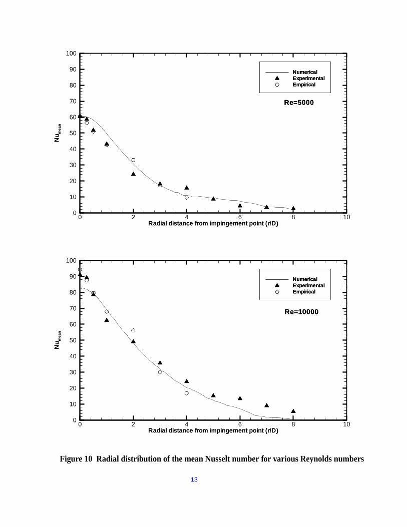
The mean Nusselt distribution is studied for
several Reynolds numbers and compared with
both the experimental data and an empirical
correlation [6]. The mean Nusselt number
distribution is provided in Figure 10. There is
satisfactory agreement between the experimental
data and the numerical results at Reynolds
number of 5000. The difference in mean Nusselt
number at the impingement point (r=0) is only
0.6%. The difference between the numerical and
empirical values is only 0.8%. There is a slightly
bigger difference at Reynolds number of 10000
(9% and 12%). The predicted distribution of the
Nusselt number agrees with both the
experimental and empirical curves.

wall
wallwall
outlet
plate
inlet
1D
5D
16D
x
r (y)
0.08D
Figure 8 Domain of the numerical simulation
X
YZ
Reference vector = 1.9m/s
-1 -0.5 0 0.5
FIgure 9 Instantaneous velocity vector plot at the impingement region (t=12s)
Re=10000
12
Radial distance from impingement point (r/D)
Nu m
ean
0 2 4 6 8 100
10
20
30
40
50
60
70
80
90
100
Radial distance from impingement point (r/D)
Nu m
ean
0 2 4 6 8 100
10
20
30
40
50
60
70
80
90
100
NumericalExperimentalEmpirical
Re=5000
NumericalExperimentalEmpirical
Re=5000
Radial distance from impingement point (r/D)
Nu
mea
n
0 2 4 6 8 100
10
20
30
40
50
60
70
80
90
100
Radial distance from impingement point (r/D)
Nu
mea
n
0 2 4 6 8 100
10
20
30
40
50
60
70
80
90
100
NumericalExperimentalEmpirical
Re=10000
NumericalExperimentalEmpirical
Re=10000
Figure 10 Radial distribution of the mean Nusselt number for various Reynolds numbers
13

14
After validating this model in a continuous
casting domain and conducting grid
dependency studies, reliable heat transfer
predictions in the actual process will be
obtained. The results obtained from studies
with this model will provide valuable insights
into defects in the process.
Further details on the work introduced here are
given in Reference 7.
References:1. J. Herbertson, O.L. He, P. J. Flint, and R.
B. Mahapatra: in 74th
Steelmaking
Conference, Iron & Steel Society,
Warrendale, PA., pp. 171-185, 1991.
2. T.A. Honeyands and J. Herbertson,
“Oscillations in Thin Slab Caster Mold
Flows”, 127th ISIJ Meeting, March, 1994,
Tokyo, Japan.
3. R. Rogallo and P. Moin, “Numerical
Simulation of Turbulent Flows”, Ann. Rev.
Fluid Mechanics, vol. 16, p. 99, 1984.
3. U. Schumann, “Subgrid Scale Model for
Finite Difference Simulations of Turbulent
Flows in Plane Channels and Annulii”, J.
Comput. Phys., vol. 8, pp. 376-404, 1975.
4. Huang, X., and B.G. Thomas, “Modeling
of Transient Flow Phenomena in
Continuous Casting of Steel”, Canadian
Metallurgical Quarterly, 1998, vol. 37, no.
304, pp. 197-212, 1998.
5. Hollworth, B. R. and Gero, L. R.
“Entrainment Effects On Impingement
Heat Transfer, Part II – Local Heat
Transfer Measurements”, ASME Journal
of Heat Transfer, vol. 107, p. 910, 1985.
6. Jambunathan, K., Lai, E., Moss, M. A. and
Button, B. L. “A Review Of Heat Transfer
Data For Single Circular Jet
Impingement”, Int. Journal of Heat and
Fluid Flow. vol. 13, no. 2, p. 106, 1992.
7. Thomas, B.G., ed., “Mathematical Models
of Continuous Casting of Steel Slabs”,
Annual Report to Continuous Casting
Consortium, UIUC, August 19, 1999.
Acknowledgments: The authors wish to
thank students Hua Bai, Sivaraj
Sivramakrishnan, Shanker Subramanian, and
Tiebiao Shi for results referred to in this paper
and for help with preparation of figures.
Funding from the National Science Foundation
(Grant # DMI9800274) and the Continuous
Casting Consortium (Allegheny Ludlum Steel,
Brackenridge, PA; Armco, Inc., Middletown,
OH; Columbus Stainless Steel, Middelburg,
South Africa; Inland Steel Co., East Chicago,
IN; LTV Steel Co., Cleveland, OH; and
Stollberg Inc., Niagara Falls, New York) is
gratefully acknowledged. Finally, thanks are
extended to the National Center for
Supercomputing Applications at the University
of Illinois for computing time and use of the
CFX code.