Embed Size (px)
Citation preview

Study on ATM enhancement and
Simulation software design
Wei Lu
Radio Engineering Department
Southeast University
A dissertation submitted for the degree of Bachelor of Engineering
June 2000

Southeast University Degree Dissertation
Radio Engineering Department Southeast University 2
ACKNOWLEDGEMENT
I would like to thank my supervisor, Dr. Xiangning Chen. It was my great pleasure
to work under his guidance.
Thanks for my labmates, Qiong Guo, Xiaodan Wang, for their warm discussion
and useful suggestions.
Last but not the least, I would like to thank the National Mobile Commun. Res.
Lab for providing me such an excellent research environment.

Southeast University Degree Dissertation
Radio Engineering Department Southeast University 3
ABSTRACT
The ATM technique was designed to achieve the goal of integration of multiple
service, high quality of service, reliable transmission and high-speed network.
However, some of its shortcomings weaken its abilities to applications. The fatal one
is its low efficiency when supporting data traffic. To keep its existence, the original
standard must be upgraded.
The main work of this paper made an attempt to improve the standard ATM
protocol and bring forward a next-generation ATM protocol. By defining a novel cell
structure, new ATM reinforces the end-to-end error control ability, and greatly
increases the data transmission efficiency. The introduction of micro cell further
enhances the support of low-speed real-time service. A simulation plat- form based on
the ns simulator, Linux OS and PC was built. These discrete event-driven simulations
focus on CBR, Web, FTP transmission delays and link utilizations in both wired and
wireless environments. The simulation results of the new protocol were analyzed. The
results showed that, these modifications can overcome the shortcomings of the
existing ATM protocol and upgrade its ability to support more services efficiently.
Key Words:
Internet, ATM, TCP/IP, Simulation, ns simulator, Linux

Southeast University Degree Dissertation
Radio Engineering Department Southeast University 4
CONTENT
Study on ATM enhancement and Simulation software design ......................................1
ACKNOWLEDGEMENT.....................................................................................2
ABSTRACT...........................................................................................................3
CONTENT.............................................................................................................4
Chapter 1. Introduction........................................................................................6
1.1 Basic principle of ATM ...........................................................................6
1.1.1 B-ISDN protocol reference Model................................................6
1.1.2 ATM Cell structure .......................................................................7
1.1.3 ATM Classes of Services and ATM Adaptation Layer (AAL) ....7
1.2 Internet and its protocols..........................................................................8
1.2.1 A brief History of the Internet.......................................................8
1.2.2 TCP/IP protocol ............................................................................9
1.2.3 IPng : Ipv6 ...................................................................................12
1.3 The combination of TCP/IP and ATM ..................................................13
1.3.1 Current situation..........................................................................13
1.3.2 Local Network Emulation (LANE) ............................................14
1.3.3 Classical IP over ATM (CIPOA)................................................16
1.3.4 Multiprotocol Over ATM (MPOA) ............................................18
1.3.5 Multiprotocol Label Switching (MPLS) .....................................18
Chapter 2. Study on the next generation ATM..................................................20
2.1 ATM’s Failure........................................................................................20
2.2 Basic considerations ...............................................................................21
2.3 Cell structure ..........................................................................................22
2.4 Cell structure definition .........................................................................26
2.5 Switching Policy....................................................................................27
2.6 Traffic Management ...............................................................................28
Chapter 3. The simulation platform...................................................................32
Southeast University Degree Dissertation
Radio Engineering Department Southeast University 5
3.1 The event-driven simulation mechanism...............................................32
3.2 VNSim software design .........................................................................33
3.2.1 Theory.........................................................................................33
3.2.2 Software design...........................................................................34
3.3 ns simulator............................................................................................35
3.3.1 Introduction.................................................................................36
3.3.2 How to get the ns ........................................................................37
3.3.3 Installation on Linux ...................................................................37
3.3.4 Analysis to the design of the ns ..................................................38
3.3.5 Use of the ns ................................................................................41
3.3.6 Extending the ns..........................................................................42
3.3.7 Shortcomings of the ns ................................................................43
3.4 Extensions to the ns and the realization of the next generation ATM
protocol ........................................................................................................43
3.4.1 New ATM Cell............................................................................43
3.4.2 Implementation of the new Agents .............................................44
3.4.3 Other modifications .....................................................................45
3.4.4 Experience and conclusion..........................................................46
Chapter 4. Simulations for the next generation ATM .......................................48
4.1 Integrated services simulations ..............................................................48
4.1.1 Simulation scene .........................................................................48
4.1.2 Simulation results........................................................................49
4.2 Wireless network simulation..................................................................54
4.2.1 Summary.....................................................................................54
4.2.2 Simulation model........................................................................55
4.2.2 Simulation result .........................................................................56
CONCLUSION....................................................................................................59
REFERENCES ....................................................................................................60

Southeast University Degree Dissertation
Radio Engineering Department Southeast University 6
Chapter 1. Introduction
As the social and economy develop, the demand of people for information
increases rapidly. For Example, communication services develop from narrow band
telephone and data to broadband video and multi-media. Existing network cannot
satisfy the development of these broadband services. The requirement to build a
network with broadband and few limits is urgent. On the technical option of
construction broadband network, there are a lot of choices. IP and ATM are the most
important of them.
1.1 Basic principle of ATM
ATM (Asynchronous Transfer Mode) is a technology that has its history in the
development of broadband ISDN in the 1970s and 1980s. Technically, it can be
viewed as an evolution of packet switching and utilizes fixed- length cells to carry
different types of traffic and hardware switching to achieve high performance. ATM
technology had been selected by ITU-T as the new tool for voice, data, television and
multi-media transmission and the foundation of Broadband Integrated Services
Digital Network (B-ISDN).
1.1.1 B-ISDN protocol reference Model
In the I.321 recommendation of ITU-T, B-ISDN protocol reference model has
been defined. It looks like the following picture.
Figure 1.1 B-ISDN protocol reference model
Southeast University Degree Dissertation
Radio Engineering Department Southeast University 7
This reference model is divided into three planes. The User plane (U-plane)
provides the transfer of user application information. In Figure 1.1, the U-plane
contains all of the ATM layers. The next plane in this model is the Control plane
(C-plane). The C-plane provides the control functions necessary for call connection
and release as well as functions for switched services. The C-plane shares the Physical
and ATM layers with the U-plane, and contains AAL functions dealing with signaling.
The final plane is the Management plane (M-plane). This plane provides the
management functions and the capability to transfer information between the C and
U-plane. The M-plane contains two sections, Layer and Plane Management. The
Layer Management performs layer-specific management functions, while the Plane
Management deals with the complete system.
1.1.2 ATM Cell structure
CCITT defines ATM 1 as follows: ATM is a kind of transfer model, in which
information are formatted by cells. The appearance of cells that contain pieces of
information does not need to be periodical. In this point, this kind of transfer model is
asynchronous. In this definition, ATM cell is the basic unit of service management.
The cells with fixed- length consist of 48 bytes (8 bits per byte) of payload and 5 bytes
of cell header. The fixed cell size ensures that long data frames or packets do not
adversely affect time-critical information such as voice or video. The header is
organized for efficient switching in high-speed hardware implementations and carries
payload-type information, virtual-circuit identifiers, and header error check.
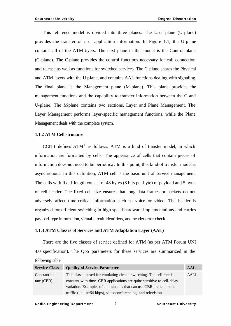
1.1.3 ATM Classes of Services and ATM Adaptation Layer (AAL)
There are the five classes of service defined for ATM (as per ATM Forum UNI
4.0 specification). The QoS parameters for these services are summarized in the
following table.
Service Class Quality of Service Parameter AAL
Constant bit rate (CBR)
This class is used for emulating circuit switching. The cell rate is constant with time. CBR applications are quite sensitive to cell-delay variation. Examples of applications that can use CBR are telephone traffic (i.e., n*64 kbps), videoconferencing, and television
AAL1

Southeast University Degree Dissertation
Radio Engineering Department Southeast University 8
Variable bit rate-non-real time (VBR-NRT)
This class allows users to send traffic at rate that varies with time depending on the availability of user information. Statistical multiplexing is provided to make optimum use of network resources. Multimedia e-mail is an example of VBR-NRT
AAL2
Variable bit rate--real time (VBR-RT)
This class is similar to VBR-NRT but is designed for applications that are sensitive to cell-delay variation. Examples for RT VBR are voice with speech activity detection (SAD) and interactive compressed video
AAL2
Available bit rate (ABR)
This class of ATM services providers rate-based flow control and is aimed at data traffic such as file transfer and e-mail. Although the standard does not require the cell transfer delay and cell-loss ratio to be guaranteed or minimized, it’s desirable for switches to minimize delay and loss as much as possible. Depending upon the state of congestion in the network, the source is required to control its rate. The user are allowed to declare a minimum cell rate, which is guaranteed to the connection by the network.
AAL3,4 / AAL5
Unspecified bit rate (UBR)
This class is the catch-all, other class and is widely used today for TCP/IP.
AAL3,4 / AAL5
1.2 Internet and its protocols
1.2.1 A brief History of the Internet
Internet is the present largest computer network in the world. The history of
Internet can be traced back to 1969, Advanced Research Projects Agency (ARPA) of
American Department of Defense established the APARNET. As ARPANET grew
out of a military-only network to add subnetworks in universities, corporations, and
user communities, it became known as the Internet. There is no single network called
the Internet, however. The term refers to the collective network of subnetworks. The
one thing they all have in common is TCP/IP as a communications protocol.
Now, almost thirty years after the first designs, there are thousands of networks
comprising the internet, serving an estimated 45 million computers and 150 million
users. By the end of 1996, according to incomplete statistical, this network has
included more than 100 countries in the world and the commercial activity on
network has exceeded 6.5 billion dollars.
The internet in China also has achieved great progress. The first unit that
connected to the internet in China was the Institute of High Energy Physics, Chinese
Academy of Sciences (www.ihep.ac.cn). Today, there are two other networks

Southeast University Degree Dissertation
Radio Engineering Department Southeast University 9
connecting to the internet in China. They are Chinese educational research network
(CERNET) and the ChinaNet which provides public services. The ChinaNet is
managed by Ministry of Posts and Telecommunications. It is the backbone network of
Chinese internet and the only network which can carry out the commercial activities.
In the ChinaNet, the regional distribution of Post and Telecommunications Ministry
take the responsibility for the connection of end-user to Internet as the Internet
Service Providers (ISP). From these ISPs, end-users have variable choices such as
dial-up, ISDN, ADSL, etc. The basic services that Internet now offers include
electronic mail (Email), remote terminal (Telnet), file transmission (FTP-File Transfer
Protocol), electronic bulletin board system (BBS) , news (Usenet) , document retrieve
(Archie), keyword inquiry WAIS( Wide Area Information Service) , menu retrieve
(Gopher), interactive information retrieve WWW( World Wide Web) and so on.
1.2.2 TCP/IP protocol
TCP/IP’s architecture
TCP/IP is the most successful network architecture and protocol set. It shields the
discrepancy of various physical networks, make Internet a unified computer network.
The Internet architecture and the position of TCP/IP are showed in Fig.1.2 and
Fig.1.3.
Figure 1.2. Internet architecture
Southeast University Degree Dissertation
Radio Engineering Department Southeast University 10
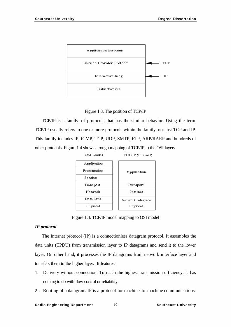
Figure 1.3. The position of TCP/IP
TCP/IP is a family of protocols that has the similar behavior. Using the term
TCP/IP usually refers to one or more protocols within the family, not just TCP and IP.
This family includes IP, ICMP, TCP, UDP, SMTP, FTP, ARP/RARP and hundreds of
other protocols. Figure 1.4 shows a rough mapping of TCP/IP to the OSI layers.
Figure 1.4. TCP/IP model mapping to OSI model
IP protocol
The Internet protocol (IP) is a connectionless datagram protocol. It assembles the
data units (TPDU) from transmission layer to IP datagrams and send it to the lower
layer. On other hand, it processes the IP datagrams from network interface layer and
transfers them to the higher layer. It features:
1. Delivery without connection. To reach the highest transmission efficiency, it has
nothing to do with flow control or reliability.
2. Routing of a datagram. IP is a protocol for machine-to-machine communications.

Southeast University Degree Dissertation
Radio Engineering Department Southeast University 11
The Address Resolution Protocol (ARP/RARP) provides a mechanism for IP
device to locate the hardware address of other devices, and the IP address of a
datagram locates the next hop of the transmission.
3. Error control. IP usually work together with Internet Control Message Protocol
(ICMP). ICMP is responsible for checking and generating messages on the status
of devices on a network. But how to handle the error messages is determined by
specific applications.
TCP Protocol
Transmission Control Protocol (the TCP part of TCP/IP) provides reliable transfer
of data based on IP protocol. It is responsible for assembling data passed from
higher-layer applications into standard packets and ensuring that the data is
transferred correctly. An example of encapsulation of data packets for Ethernet is
showed in Fig.1.5
Since TCP is based on unreliable IP protocol, it realizes the reliability by itself.
This work includes the following aspects2:
1. TCP acts as a message-validation protocol and handles the retransmission to
guarantee the reliability.
2. TCP implementation usually performs a simple flow control using a sliding
window whose length and the transmission of data packets in which are
controlled by ACK signals of TCP protocol.
Southeast University Degree Dissertation
Radio Engineering Department Southeast University 12
3. The end-to-end congestion control is also based on sliding window mechanism.
1.2.3 IPng : Ipv6
The crisis of IPv4
When IP version 4 (the current release) was developed, the use of a 32-bit IP
address seemed more than enough to handle the projected use of the Internet. With the
incredible growth rate of the Internet over the last few years, however, the 32-bit IP
address became a problem. To counter this limit, IP Next Generation, usually called IP
version 6 (IPv6), is under development.
IPv6
The first proposals for the next generation of IP were documented in the usual
manner for Internet enhancements – a Request For Comments (RFC number 1752)
issues in 1994. It tooks a year for these proposlas to be finished which finally
happened in July 1995. Jan. 1996 saw the detailed proposals including 5 RFCs, RFC
1883,1884,1885,1886 and 1933. Comparing with IPv4 (RFC-791), major change and
characteristic include:
• 128-bit network address instead of 32-bit
• More efficient IP header with extensions for applications and options
• No header checksum
• A flow label for quality-of-service requirements
• Prevention of intermediate fragmentation of datagrams
• Built-in security for authentication and encryption
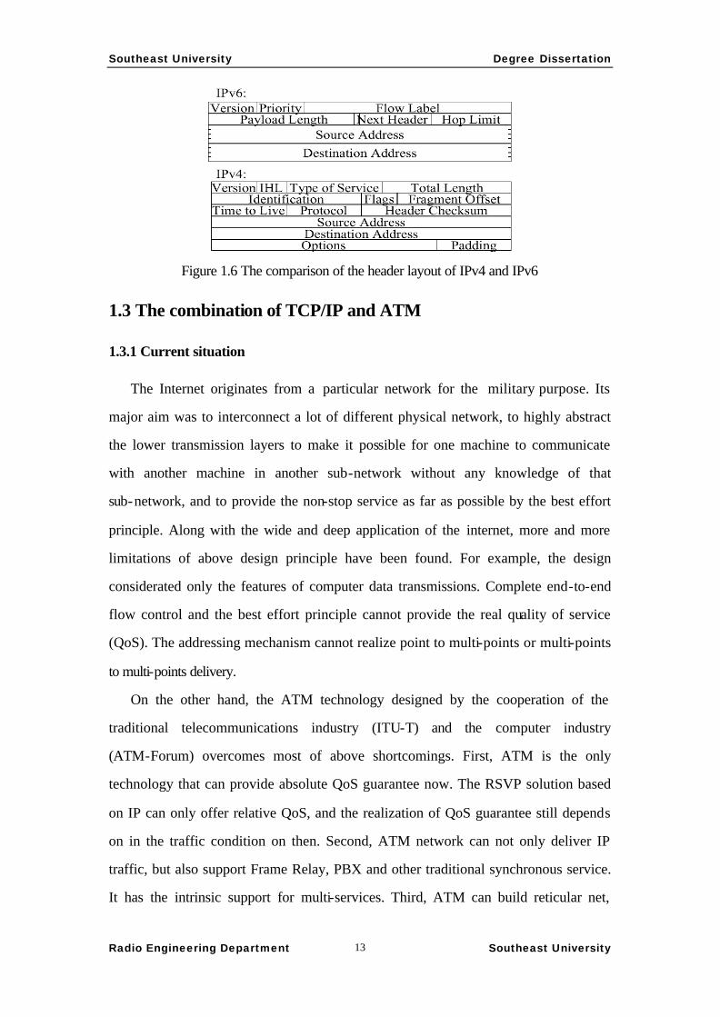
IPv6 datagram header
The variation of the protocol is obvious by comparing the variation of the diagram
header layouts, which is shown in the Figure 1.6.
Southeast University Degree Dissertation
Radio Engineering Department Southeast University 13
Figure 1.6 The comparison of the header layout of IPv4 and IPv6
1.3 The combination of TCP/IP and ATM
1.3.1 Current situation
The Internet originates from a particular network for the military purpose. Its
major aim was to interconnect a lot of different physical network, to highly abstract
the lower transmission layers to make it possible for one machine to communicate
with another machine in another sub-network without any knowledge of that
sub-network, and to provide the non-stop service as far as possible by the best effort
principle. Along with the wide and deep application of the internet, more and more
limitations of above design principle have been found. For example, the design
considerated only the features of computer data transmissions. Complete end-to-end
flow control and the best effort principle cannot provide the real quality of service
(QoS). The addressing mechanism cannot realize point to multi-points or multi-points
to multi-points delivery.
On the other hand, the ATM technology designed by the cooperation of the
traditional telecommunications industry (ITU-T) and the computer industry
(ATM-Forum) overcomes most of above shortcomings. First, ATM is the only
technology that can provide absolute QoS guarantee now. The RSVP solution based
on IP can only offer relative QoS, and the realization of QoS guarantee still depends
on in the traffic condition on then. Second, ATM network can not only deliver IP
traffic, but also support Frame Relay, PBX and other traditional synchronous service.
It has the intrinsic support for multi-services. Third, ATM can build reticular net,
Southeast University Degree Dissertation
Radio Engineering Department Southeast University 14
which increase the stability and the resistance of attack of network greatly. IP network
can only construct tree structure network, otherwise it will form the fatal routing
circle. Finally, using the advanced properties of PNNI, ATM can realize self-healing
and the fast reestablishment of connection, traffic equalization on multiple links,
network loading balance, and QoS routing.
Practically, the next generation of network must support not only the traditional
telecommunications services but also the increasing Internet service. It must have the
ability to offer comprehensive business. The traditional packet switching computer
network has the ability that offers asynchronous communication. While the
telecommunications networks based on time-division multiplexing and the circuit
switching technology offer the ability of real time communication. ATM technology
is the effort to unify these two patterns, support more services and raise the utilization
rate of network. Therefore, how to mix the traditional IP and ATM technology
together is the focus of research.
The combination of IP and ATM technology divide into two models. One of them
is the overlapping model and the other is integrated model. In September 1997,
Japanese NTT company has again made a new model which is called coreprotocol.
ITU-T SG 13 is doing research on it now.
In overlapping model, IP packets transmit using the ATM routing and signal
protocols based on ATM address. The ATM layer is responsible for address
resolution. In the integrated model, the end equipments should be located by IP
addresses and the IP packets must be routed with existing routing protocols such as
OSPF. The ATM connection is established by nonstandard signaling protocol.
Integrated model need not carry out address resolution, but it makes the ATM
switcher must support multiple routing protocols. This will increase the complexity of
ATM switcher greatly.
Some examples of the two models are introduced in the following.
1.3.2 Local Network Emulation (LANE)
LANE enables using existing LAN protocols on ATM network. It describes how

Southeast University Degree Dissertation
Radio Engineering Department Southeast University 15
to use the ATM network as the backbone network to interconnect the existing LAN,
as well as how to make the existing machines in Ethernet and Ring network equally
communicate with the machines equipped with ATM interface. LANE is
implemented as a device driver below the network layer (shown in Fig.1.7).
Figure 1.7 LANE protocol layer
The ATM layer manages the header of ATM cell. It takes over the cell data sent
by higher layer, adds the header, and then delivers the synthetic 53-bytes cell to the
physical layer. Conversely, ATM layer accepts the ATM cell from physical layer,
removes the header, and then gives the 48-bytes payload to higher layer. Although
ATM layer can distinguish different QoS requirement according to the relevant
information during establishing connection, it does not know what type of information
is been transmitting. The layer above the ATM layer is ATM Adaptation Layer
(AAL). AAL formats data to 48-bytes units to fit in ATM cells or assembles the
individual cell payloads to original data conversely. Since ATM can transmit various
types of information. There are various adaptation protocols in AAL. They can work
simultaneously. AAL Type 5 is used to carry out LAN emulation. LAN emulation
layer locates above AAL. In ATM LANE converter at network boundary, LAN
emulation solves the data interconnection problems for all protocols. Its method is to
establish the correspondence of MAC addresses and ATM addresses. LAN emulation
is complete independent to upper layers, services and application software. Since
LAN emulation only exists on boundary equipment and terminal system, it is
completely transparent for ATM network as well as the machines in Ethernet and
Southeast University Degree Dissertation
Radio Engineering Department Southeast University 16
Ring network. LAN emulation shields the details of connection establishment and
hands shaking actions which are required by ATM switcher. It turns the networking
protocol based on MAC address to ATM Virtual Circuit. Therefore ATM acts as a
connectionless LAN. LAN emulation defines the service interface of IP protocol.
Because the router has to be used, the bottleneck still exists, and the QoS cannot be
guaranteed.
1.3.3 Classical IP over ATM (CIPOA)
IP protocol is not only the network layer protocol for Internet, but also the
supporting protocol for many local area networks, and the foundation of
communication platforms based on Unix operating system. Lots of existing
application software of communication network is based on IP. If it’s possible to
make IP protocol run on ATM communication platform and existing applications
work continuously on ATM network, users’ investment can be protected best. IETF
has defined standards for running IP on ATM platform. Two major documents are
RFC 1483 and RFC 1577. RFC 1483 is mainly concerned with how to carry the
various existing protocols of upper layers with AAL5. RFC 1577 is mainly concerned
with how to find ATM addresses from IP addresses.
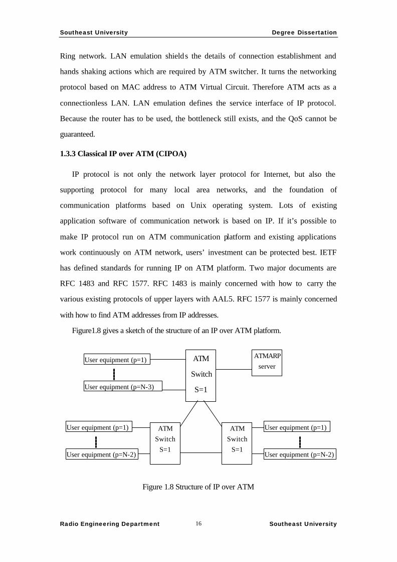
Figure1.8 gives a sketch of the structure of an IP over ATM platform.
Figure 1.8 Structure of IP over ATM
ATM
Switch
S=1
ATMARP server
ATM Switch
S=1
ATM Switch
S=1
User equipment (p=1)
User equipment (p=N-3)
User equipment (p=1)
User equipment (p=N-2)
User equipment (p=1)
User equipment (p=N-2)

Southeast University Degree Dissertation
Radio Engineering Department Southeast University 17
Every user equipment has two addresses: IP address and ATM address. The
correspondences of these addresses are stored in the ATMARP Server. All users have
established permanent or half permanent Virtual Channel Connections (VCC) to the
ATMARP server in advance. Through these VCCs, users can enquire the addresses.
The brief communication process will be like this: If user (s = 2, p = 1) has
information to transfer to another user with IP address B, he checks first in his own
ARP Cache to see whether there’s a established VCC to B. If the answer is yes, the
communication can start directly. If no, it will use ATM ARP packet to ask the
ATMARP server for the ATM address whose IP address is B. After the inquiry is
successful, establish a VCC to user B by signaling. The protocol of address resolution
and division of ATM stations refers to RFC 1577 and to RFC 1483 for the case of
packet encapsulation with AAL 5.
CIPOA now has the following problems mainly: (1) IP is suitable for data
exchange, not guaranteeing to satisfy users’ delay requirements. Theoretically, IP
over ATM cannot support real time transmit for voice and video services, ATM’s
support of real time service does not make sense. IETF has now made a kind of
resource reservation protocol, RSVP, to make IP provide the real time service by
pre-engaging the bandwidth. How to match RSVP and ATM signal is still a problem
to be solved, however. (2) IP cannot offer different QoS for specific user, while ATM
technology can make it by establishing virtual connection and allocate bandwidth for
specific user through its signaling system. Such difference will eventually cause ATM
not provide specific QoS for users. ATM’s support of multi-media services does not
make sense either. IETF hope this can be solved in IPv6. (3) TCP realizes end-to-end
flow control by sliding window mechanism. ATM realizes traffic policing with the
Leaky-Bucket algorithm. The research of Bell laboratory discovered that if these two
mechanism are used at the same time, the throughput of TCP will drop down greatly.
(4) Whether IPOA is the only way of the cooperation of IP and ATM. Research is
carried on to study whether it is possible to break the traditional layered structure to
exploit the advantage of IP and ATM each fully. This project is named GIPR (Gigabit
IP Router) (http://www.ccrc.wustl.edu/~jpgs/paper/network95.html), which started in
Southeast University Degree Dissertation
Radio Engineering Department Southeast University 18
1995 in Washington University, US.
1.3.4 Multiprotocol Over ATM (MPOA)
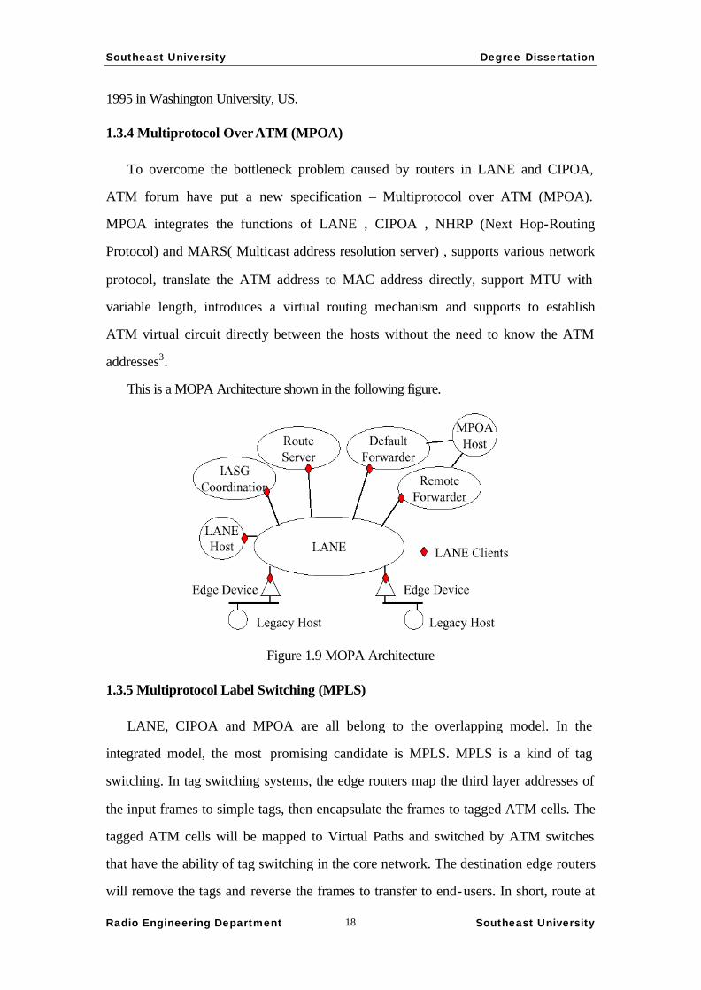
To overcome the bottleneck problem caused by routers in LANE and CIPOA,
ATM forum have put a new specification – Multiprotocol over ATM (MPOA).
MPOA integrates the functions of LANE , CIPOA , NHRP (Next Hop-Routing
Protocol) and MARS( Multicast address resolution server) , supports various network
protocol, translate the ATM address to MAC address directly, support MTU with
variable length, introduces a virtual routing mechanism and supports to establish
ATM virtual circuit directly between the hosts without the need to know the ATM
addresses3.
This is a MOPA Architecture shown in the following figure.
Figure 1.9 MOPA Architecture
1.3.5 Multiprotocol Label Switching (MPLS)
LANE, CIPOA and MPOA are all belong to the overlapping model. In the
integrated model, the most promising candidate is MPLS. MPLS is a kind of tag
switching. In tag switching systems, the edge routers map the third layer addresses of
the input frames to simple tags, then encapsulate the frames to tagged ATM cells. The
tagged ATM cells will be mapped to Virtual Paths and switched by ATM switches
that have the ability of tag switching in the core network. The destination edge routers
will remove the tags and reverse the frames to transfer to end-users. In short, route at

Southeast University Degree Dissertation
Radio Engineering Department Southeast University 19
edge and switch in core.
The process of MPLS switching is completed normally through 4 steps:
§ Use existing routing protocols, for instance, OSPF and IGRP etc. to establish the
connection to the target network, then use label distribution protocol (LDP) to
achieve the mapping of the target network to a label.
§ Edge router at input end receives the packet, completes the functions of the third
layer and tags the packets.
§ Label switch switches the tagged packets.
§ The edge router at output end removes the labels and transfers the packets to
end-users.
In fact MPLS is not only a technology of IP over ATM, but also a network
technology as a middle layer between layer 2 and layer 3 and a kind of architecture in
research and development.
The characteristic of MPLS is as follows:
§ The same to No.7 signaling system, every switch has the intelligence of layer 3
which make the reconnection possible. When major relay link arises fault, MPLS
technology can minimize the interrupted service time by selecting another route to
effuse the congested traffic and make the link quickly recover.
§ MPLS uses labels as marks to seek the next hop in the routing table. This
mechanism is suitable for high-speed relay, such as STM-4, STM-16 and STM-64.
§ MPLS’s Classless Inter Domain Routing (CIDR) mechanism does not need
32–bits IP addresses. It is the concept of group address that can meet the fast
increment of Internet user quantity.
§ MPLS utilizes the VC Merge technique with which many VC with the same target
can be mixed into one VC to save the VCI resource.
§ ATM switch mixed with IP need not complex address resolution.
Southeast University Degree Dissertation
Radio Engineering Department Southeast University 20
Chapter 2. Study on the next generation ATM
2.1 ATM’s Failure
ATM technology has developmed greatly since the ITU-T decided to take it as the
B-ISDN solution in later 1980s and has been put into operation since 1993. At that
time, It has been regarded as the end technology of the public telecommunication
networks. Through a unified user network interface, variable integrated services can
be provided to business or familial users. In the beginning of 1990s, ATM had been
even regarded as the upgrade of traditional LAN and acted as a very important role of
computer network. Because of its importance, ATM standard is affected by various
non-technical factors. The result is a political compromise in which many aspects are
far from perfect. Specifically, there are the following points:
§ ATM utilizes a single cell size to simplify the switch equipment. The selection of
the cell size is the tradeoff between two conflicting requirements. One requirement
comes from low-speed real- time service. It needs small cell size to guarantee short
transfer delay. The size of 48 bytes was defined according to the requirement of
64Kbps PCM voice transmission without consider ting the development of digital
voice coding and compression technology. Today, the transfer delay requirement
for long distance transmission of 8Kbps voice or below cannot be satisfied by such
cell size. The other requirement for the ATM cell size comes from large-volume
data service. It needs large cell size to raise the transmission efficiency. But the
ratio of 5 bytes header and 48 bytes payload is already far from satisfaction even
the encapsulation expense in other layers are not counted in. In short, tradeoff
policy only dissatisfies both sides.
§ Today, the TCP/IP technology is the de-facto end standard for data transmission.
ATM must support it smoothly. But all the exciting technologies such as RFC 1488,
RFC 1577, LANE and MPOA are too complicated. They have over 20%
encapsulation and protocol expense, low efficiency and high maintenance cost but
Southeast University Degree Dissertation
Radio Engineering Department Southeast University 21
absolute QoS.
§ ATM is an absolute connection-oriented technology. When use PVC, it’s so
difficult to configure dynamically and the plug-and-play is impossible. Comparing
to the flexible IP technology, the ATM network deployment includes complicated
configuration to the switches. These complications limit the utilization of ATM
§ It’s difficult for ATM to support bi-directional point-to-multi-points connection.
In bi-directional point-to-multi-points connection, ATM cells sending from several
points may interleave among each other when they arrive at the receiver. AAL 5
cannot reassemble these interleaved cells into their original message form.
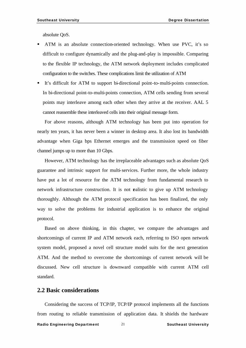
For above reasons, although ATM technology has been put into operation for
nearly ten years, it has never been a winner in desktop area. It also lost its bandwidth
advantage when Giga bps Ethernet emerges and the transmission speed on fiber
channel jumps up to more than 10 Gbps.
However, ATM technology has the irreplaceable advantages such as absolute QoS
guarantee and intrinsic support for multi-services. Further more, the whole industry
have put a lot of resource for the ATM technology from fundamental research to
network infrastructure construction. It is not realistic to give up ATM technology
thoroughly. Although the ATM protocol specification has been finalized, the only
way to solve the problems for industrial application is to enhance the original
protocol.
Based on above thinking, in this chapter, we compare the advantages and
shortcomings of current IP and ATM network each, referring to ISO open network
system model, proposed a novel cell structure model suits for the next generation
ATM. And the method to overcome the shortcomings of current network will be
discussed. New cell structure is downward compatible with current ATM cell
standard.
2.2 Basic considerations
Considering the success of TCP/IP, TCP/IP protocol implements all the functions
from routing to reliable transmission of application data. It shields the hardware

Southeast University Degree Dissertation
Radio Engineering Department Southeast University 22
difference and details of infrastructure. TCP/IP is user oriented and can be
implemented completely with software. It’s relatively easy to implement a TCP/IP
stack in computer operation system. Therefore, it’s easy to popularize this technology.
Being the most successful protocol in history, the TCP/IP traffic flows through the
backbone network are increasing greatly. Because the IP protocol has the routing
ability by itself, the propositions of IP Over SDH, IP over OPTICS are reasonable. In
this point, removing the ATM layer in the current structure of IP/ATM/SDH is
possible. So, the overlapping model indicated in chapter one is almost hopeless.
Comparing to IP protocol, ATM has its own addressing, routing ability. What it
lacks is only the support for data stream transmission while TCP has. Therefore, we
chose a new way similar but distinguish to the integrated model. That is to expand
ATM protocol to enable it complete the functions of transmission layer and data link
layer. So the expended ATM covers the functions of both IP and TCP and it is
possible to avoid carrying the TCP/IP protocol.
Corresponding to the successful experience of TCP/IP, the new protocol can be
firstly implement as a software protocol stack in computer operation system running
on existing physical networks. After protocol gets popular, the hardware support for
fully use of the protocol will appear naturally. So the upgrade of hardware equipment
will be more smoothly. If this happens, ATM technology will not only realize the
original intention to extend to desktop application but also exists longer. The research
on such a kind of new protocol set is undoubtedly complicated. we referred to some
examples that have identical research technique and purpose45.
2.3 Cell structure
The most notable characteristic of ATM is the cell structure and the major
problem also exists in this structure. Therefore, new design of cell structure is
necessary. The standard cell structure is shown in Figure 2.1 2.2 and 2.3. The cell
header formats in Network-Node Interface (NNI) and User-Network Interface (UNI)
are similar. The only difference is the GFC section in UNI is replace by another 4 bits
VPI in NNI. The General Flow Control (GFC) field is reserved in ATM standard. The

Southeast University Degree Dissertation
Radio Engineering Department Southeast University 23
standardization organization encourages further research on its usage in applications.
This field is not defined yet which means it can be utilized in the new standard.
Figure 2.1 ATM Cell Header in UNI Figure 2.2 ATM Cell header in NNI
5 bytes Header
48 bytes Payload
Figure 2.3 ATM Cell Layout
The ATM address management method that is different from IP need not to
allocate a fix for each network node. The VPI/VCI with addressing function is
allocated dynamically in the connection establishment. The limit of address space in
IPv4 doesn’t exist here and VPI/VCI does not have the requirement to extend.
There are some enhancements for QoS in IPv6 such as the Flow Label. These
functions are completed in ATM by the negotiation before the establishment of
connection. Then consider TCP fragment structure. There are no counterpoints in
ATM to the sequence number and confirmation number of TCP. IP can not provide
reliable connection. TCP has to achieve the reliability by confirmation and
retransmission mechanism with these two fields. Although ATM protocol is designed
mainly for high speed link that is above 155Mbps and these high speed link can
guarantee very low transmission error with the fiber technology, so long as keeping
the high link utilization, congestion and cell drop must exist and raise the transmission
error. That is the major reason for ATM to carry TCP/IP to provide reliable
transmission. Therefore for, one of most crucial probable improvements to ATM is to

Southeast University Degree Dissertation
Radio Engineering Department Southeast University 24
add the correspondent control fields.
The problems of ATM technology problem also lie in the cell length. The length
of 53 bytes is a tradeoff under some non-technical considerations and the technology
development decades ago. First, 53 bytes cell size with 48 bytes payload meet the
requirement of the voice coding standard, PCM 64kbps. With AAL0, AAL1 and
AAL2, the biggest assemble delay is between 3~6 ms 6 . But along with the
development of data compression and the speech coding technology, bit rate greatly
drops. Now, the standards being used widely are G.729 CS_ACELP 8kb/s, G.728
LD_CELP 16kb/s, G.723.1 MPC-MLQ 5.3&6.4kb/s, etc 7 . Considering G. 729,
coded frame length is 10ms, 10 bytes, even if a ATM cell carries only one frame with
the efficiency of 20%, the adaptation delay is 10ms, reaches the lower limit of human
discretion. Second, considering the aspect of computer data transmission, TCP/IP
protocol is widely adopted. Statistics shows that 80% TCP segments are shorter than
512 bytes8. Take a 512 bytes TCP segment for an example, the protocol expense can
be calculated as the following table (unit is byte):
Application
Layer
TCP
Layer
IP
Layer
LLC
encapsulation
AAL
5
ATM Total
Expense
Efficiency
512 532 552 560 576 636 124 80.5%
Such low efficiency is caused mainly by the ATM Cell header expense of 10%.
Further more, a 512 bytes segment must be divide into more than 10 cells. Any of
them loses will cause the retransmission of the whole 512 bytes segment. The
efficiency will drop down further.
The contradiction is obvious that voice transmission requires smaller cells to
guarantee some qualities but computer data transmission needs larger cells to improve
the efficiency. If we adopt the variable length mechanism as it is in many computer
communication protocols, the switch structure will be too complex and the advantage
of hardware switching will lose. This problem was also discussed when ATM
standard was defining. But it seems that the compromise is already outdated.
On the wireless and narrowband application field that ATM does not consider
Southeast University Degree Dissertation
Radio Engineering Department Southeast University 25
originally, there are problems in the cell structure. Because of the high cost to
establish B-ISDN network and the application bandwidth requirement, narrowband
ATM network of 10Mbps or below has more demand. The research is also very
active9. B-ISDN transmission with fiber can guarantee the transmission error of 10-10
but narrowband ATM network usually utilizes rent channel or wireless channel with
transmission error of 10-4 or 10-5, sometimes up to 10-3. Therefore, there are two
problems must be considered. One is that it needs to reduce the cell size to satisfy the
real-time service when the transmission delay increases in narrowband channel. The
other is to strengthen the header error control (HEC) function
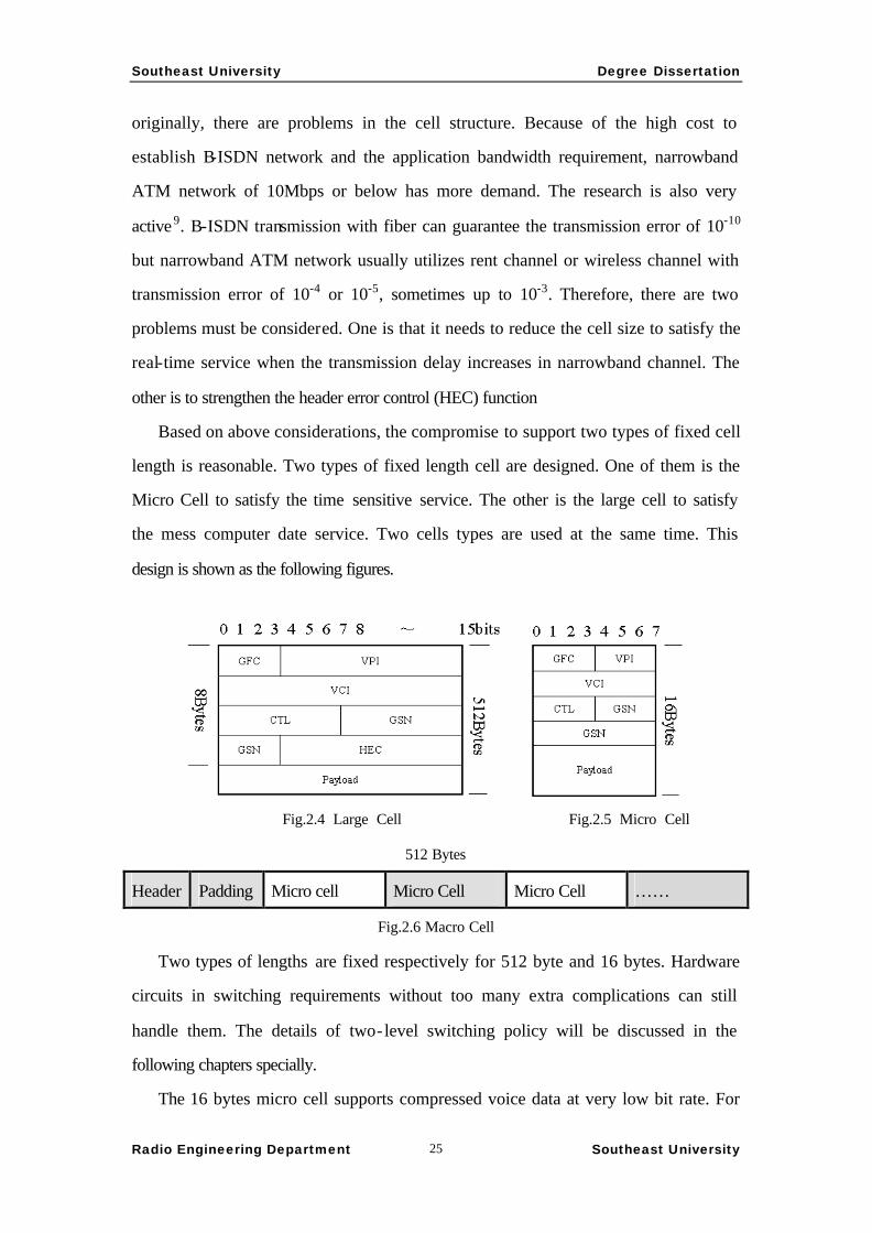
Based on above considerations, the compromise to support two types of fixed cell
length is reasonable. Two types of fixed length cell are designed. One of them is the
Micro Cell to satisfy the time sensitive service. The other is the large cell to satisfy
the mess computer date service. Two cells types are used at the same time. This
design is shown as the following figures.
Fig.2.4 Large Cell Fig.2.5 Micro Cell
512 Bytes
Header Padding Micro cell Micro Cell Micro Cell … …
Fig.2.6 Macro Cell
Two types of lengths are fixed respectively for 512 byte and 16 bytes. Hardware
circuits in switching requirements without too many extra complications can still
handle them. The details of two- level switching policy will be discussed in the
following chapters specially.
The 16 bytes micro cell supports compressed voice data at very low bit rate. For
Southeast University Degree Dissertation
Radio Engineering Department Southeast University 26
example, after encapsulating a G.729 frame, there are two more bytes surplus in the
payload, which can be used for error detection and correction.
There are two types of cells whose length is 512 bytes, large cell and macro cell.
Large cell carries data directly, mostly for computer data transmission. Because the
payload field is extended greatly, the efficiency can reach more than 98%. Macro cell
is used to pack micro cells. Because the length of micro cell is too short to fill enough
information for switching, micro cell exists only in between terminal equipments (TE)
and broadband network terminals (B-NT). In the transmission between NTs, micro
cells must be packed into macro cells. One macro cell can contain 1~31 macro cells.
Actual number should be decided by delay requirements. Besides real-time services,
control cells such as RM cell also can be implemented by micro cell. For this reason,
in practical operation, the fill ratio of macro cell will not be too low and if the delay
requirement is strict, higher expense by low fill ratio is worthy.
The header structure of macro cell keeps uniform to the one of large cell by 8
bytes padding right after the header. So the switch can cut out the micro cells simply
by hardware circuit. The usage of the padding field should be studied on and on.
Maybe it can carry the checksum of the whole macro cell or the counter of packed
micro cell.
2.4 Cell structure definition
Each field is explained as below:
§ GFC, general flow control field. ATM standard does not fully use this field. In
practical applications, these 4 bits are all set to 0. For the compatible reason, we
make following definition: The first bit defines as the version specification. 0
indicates the existing version of ATM standard, 1 indicates the version of the next
generation ATM. The second bit is reserved. The third and fourth bits indicate the
cell type: 00 is large cell, 01 is macro cell, 10 is micro cell. The complete GFC
field exists in all the three types of cells, which keeps the compatibility.
§ VPI and VCI are extended to meet the network development. As long as the
compatibility and the requirement of switching between edge terminal and home

Southeast University Degree Dissertation
Radio Engineering Department Southeast University 27
edge switch can be satisfied, VPI/VCI can be shorten properly.
§ CTL, an 8 bits control field includes the original Payload Type (PT) field and
Cell Loss Priority (CLP) field to guarantee the compatibility. The usage of the
extra 4 bits can be studied continuously.
§ GSN, 12 bits general sequence number, which is defined by transport layer. For
computer data, it can be defined as the sequence number in the unit of cell. Such a
sequence number make it possible to implement reliable transmission by
confirmation and retransmission without the help of TCP. For real- time
applications, it can be treated as a generating-time-stamp for macro cell for
reassembling of multiple data streams or transmission delay control. The field is
one of the most important enhancements.
§ HEC, 12 bits header error control. The header length is 8 bytes. With this field, 2
error bits can be corrected. The ability of error control is raised.
2.5 Switching Policy
The novel switching policy is designed for the two fixed cell sizes. To keep
compatible, whenever a cell arrives in a switch, the GFC field is first read and
different switching policy is applied to different cell type.
§ The exchange of big cell is identical with traditional ATM cell. In backbone
network, high speed can be achieved because the switches consider only one cell
size.
§ Macro cell acts as the tunnels for micro cells to be transferred across the
backbone network. The home edge switch creates a tunnel when low-speed
real-time connection is setup. And a macro cells are created whenever a micro
cells needs it. The generation time can be recorded in the GSN field. New
generated macro cell is not obligate to be sent off at once. It’s stored in a buffer
until (a) the macro cell has lingered enough time, or (b) the macro cell has been
filled by enough micro cells.
§ Micro cell exists only between the end terminal and its home edge switch. When
a micro cell arrives the edge switch, the edge switch sends it off directly if it’s

Southeast University Degree Dissertation
Radio Engineering Department Southeast University 28
not going to the backbone networks. Otherwise, the edge switch search the
buffer for a macro cell with the same direction and put the micro cell in its train.
If there’s no matching macro cell, a new one will be created. When a macro cell
arrives in the destination edge switch, its header is simply removed and the
micro cells will be switched according to their own identifiers. Because the
length of macro cell is integral multiple of the length of micro cell, it’s not too
complicated to share the same buffer by the macro and micro cells in the edge
switch.
2.6 Traffic Management
The existing ATM service classification is perfect enough to use continuously.
In traditional ATM, CBR, VBR and UBR are all non-control services. Only ABR
has network-based traffic control. But the ABR service is quite complicated to
implement and utilize. So it’s used in practice infrequently. Basically, it is the
computer data transmission requires traffic management most. Currently, such
services are handled as UBR service. The sliding windows mechanism of TCP
implements the end-to-end traffic control.
Because of the introduction of the GSN filed as the sequence number, it’s possible
to utilize the sliding window mechanism without the TCP layer. But we prefer the
network-based traffic management for the connection-oriented character. New
mechanism refers to the standard of ABR service. The aim is to simplify the
operations. The name of ABR is inherited but there is a bit of difference.
Figure 2.7 CBR,VBR,ABR services share the bandwidth

Southeast University Degree Dissertation
Radio Engineering Department Southeast University 29
Figure 2.8 Bandwidth share in ABR service
Each ABR flow can require a minimal cell rate and this minimal bandwidth will
be guaranteed if the connection can be established. Then, ABR service uses rate-based
flow control to realize the extra bandwidth fair share among each ABR connections.
When congestion happens, the extra share should be cut down and the traffic source
should be informed. The research focuses on two aims. One is the bandwidth fair
share algorithm with fast convergence speed. The other is the efficient congestion
indication mechanism.
Referring to the algorithms for traditional ABR service, the following schemes are
designed.
A. Binary rate feedback
1. EFCI algorithm.
The basic thinking is that the ABR source sends one RM cell for every Nrm-1
data cells. There is a congestion indication bit, EFCI, in the header of the data
cells. Initial value of the EFCI bit is zero. The switch may set it according to the
local congestion situation. The destination saves the CI information when it
receives the data cells. When RM cells are received, the CI information in them
may be changed according to the saved CI information from data cells. The RM
cells should be returned to the source to make it raise the current cell rate (CCR)
when the CI bit is set or reverse. Traditionally, the value of Nrm is 32; RM cell
and data cell have same length.
In our design, RM cell uses micro cell size. In order to reach the similar interval

Southeast University Degree Dissertation
Radio Engineering Department Southeast University 30
of flow control, the value of Nrm must be reduced. For instance, the value of 8 is
reasonable.
2. Enhanced EFCI algorithm.
EFCI algorithm is simple to implement that the switch may monitor the local
congestion situation by comparing the shared buffer queue length to the threshold.
But the feedback information to the source is too little. The source has no idea of
the quantity of increase or decrease of CCR.
In our opinion, the enhancement is as follows:
RM cell does not send out from data source but directly from switches. It will
speed up the congestion indicating process. The extra 4 bits in the CTL field of
the cell header can be used as source distance indication (SD). It’s initialized to
zero when sent off from the source. And it should be increased by one when
passes a switch. The switch records the Max and Min distance (MAXD and
MIND) it has ever seen in the cells past by.
when the switch determines congestion is occurring, it will send RM cell with
congestion indication to every active connection. A relative change percentage
will be carried too. This percentage is calculated by comparing the SD of the
specific active connection to the MAXD and MIND that are recorded in this
switch. The value is big when the SD this small, or vise versa. The source should
change its CCR according to the relative change percentage in the received RM
cells. In this way, the cell rate in the node near the congestion varies fast.
Considering the situation that the transmission delay can not be ignored and the
congestion indication needs long time to be diffused, e.g. the practical wide area
network (WAN), this policy should provide better equality of bandwidth share
and speed of the elimination of congestion.
B. Explicit rate feedback
1. ERICA algorithm.
The basic thinking is that the source sends the RM cells as in EFCI algorithm.
The ACR field takes the shoes of the CI bit. Its initial value is the PCR. The
switching nodes in the network change the ACR field. When the RM cell comes

Southeast University Degree Dissertation
Radio Engineering Department Southeast University 31
back to the source, the CCR of the source should be updated to the value of ACR.
The way to calculate the value of ACR is:
To calculate the current node load factor z = the sum of ABR input rates / ABR
target bandwidth.
To calculate the Fair Share (FS) = ABR target bandwidth / he number of active
ABR connections.
To calculate the virtual connection share, VcShare (VS) =CCR/z
To calculate the explicit rate (ER) of the current node, ER=min(PCR,
max(FS,VS)).
To modify the RM cell: ACR = min (ACR, ER)
2. Improved ERICA algorithm.
Refer to the calculating method of the explicit cells rate. The generation of RM
cells is identical to the enhanced EFCI algorithm. The calculation of the ER value
of the switching nodes is same to the above algorithm. The result of the ER value
should be revised according to the source distance (SD) information which is
described in the enhanced EFCI algorithm. The distance percentage, DistPerc =
( MAXD - SD ) / ( MAXD - MIND), DeltaR = ( ER - CCR) * DistPerc,
ER = DeltaR + CCR. Then, set the ACR of RM cell to the revised ER.
These algorithms require full simulations to evaluate.
Southeast University Degree Dissertation
Radio Engineering Department Southeast University 32
Chapter 3. The simulation platform
There are two usual ways to have network research, the software simulation and
small-scale test-bed. Though the latter can get the most actual test result, the cost is
high and workload is large. It is used always in the final stage before the practical
application. On the other hand, the computer simulation for theoretical research is
inexpensive. If the software is designed considerately, the result is accurate and
reliable enough. In this chapter, the simulation software design and its application to
the research of next generation ATM are discussed.
3.1 The event-driven simulation mechanism
The network simulation can be implemented by different mechanisms:
(1) The algorithm simulation. It is the implementation of the algorithm by
computer programming language. It focuses on the evaluation of the
theoretic algorithm discarding any other practical disturbing effects.
(2) The mechanism based on numeric integral computing. The MATLAB10
is a typical example. There is a package named SIMULINK for the
MATLAB to do the network and communication system simulation.
Because the core mechanism of the MATLAB is numeric integral
computing, the data transmission is simulated by the variation of signal
voltage. It is obviously that it is far from efficient for the packet level
simulation although it is suitable for the physical layer simulation.
(3) The event-based mechanism. In this method, the communication process
is abstracted into discrete events. And the transmission data unit is
described by high level data structure but the actual data. What is
simulated is the interested part of the whole process. Others can be
ignored. What is processed is the data structure but the actual data. So the
efficiency can be improved greatly. This method is suitable for the
research focus on the layers above the data link layer.
Southeast University Degree Dissertation
Radio Engineering Department Southeast University 33
The third mechanism is most suitable for the research in this paper.
3.2 VNSim software design
In order to understand the principle of discrete event-driven simulation and study
the simulation software design, the Visual Network Simulation (VNSim) is developed.
The aim is to build a general framework for the discrete event-driven simulation. The
specific simulation software such as network simulator can be implemented based on
it. The intending features include extensibility by component based structure and the
user-friendly interface by which user can achieve the modeling jobs easy, and monitor
and control the simulation process. The development tool is Microsoft Visual C++ 5.0
on windows platform.
3.2.1 Theory
In the software simulation, the simulation time is not equal to the nature time.
Otherwise, the simulation loses its meaning. So the software must implement a
simulation clock. There are two ways to implement a clock. One is by a basic step.
According to the requirement of precision, a minimum step is set. In the runtime of
the software, when a step passes, the simulation clock passes a unit of time. The
benefit of this type of realization is to simplify the design. It is widely used in the
simulation of digital circuits, hardware description language (HDL), etc. Its
disadvantage is the difficulty of choosing the step. In the situation that different
actions to be simulated may takes widely variable time. The step is determined to the
actions that need minimum time. But for the actions need long time, the efficiency is
too low.
The other method is by an event queue. There is no fixed interval for time to pass
on. The progress of the time is determined to the sequence that the events occur.
Specifically, a global scheduling queue should be setup. Before the simulation starts,
the earliest event is put in the queue. During the simulation, the simulator processes
the events from the head of the queue one by one. For every event, the time of the
next event that should happen is calculated. For example, after a data packet was
Southeast University Degree Dissertation
Radio Engineering Department Southeast University 34
processed in a network node, the arrival time of it to the next node can be known by
calculating the transmission delay. Then, the processed event is removed from the
queue and the succeed event and its occurrence time are put into the queue. It is
compared with the events waiting to be processed in the queue and inserted into the
correct position according to the sequence of occurrence. When the simulator
processes the event in the head of the queue, the simulation clock is set to the
occurrence time of that very event. In this case, the progress of the simulation time is
not even. The time in which no event occurs is skipped. So the CPU time is not
wasted and the parallel events can be supported too.
3.2.2 Software design
Considering the Microsoft Windows is the most widely used platform and there
are a lot of tools to help to build the graphical and user- friendly programs, the choice
of Microsoft Visual C++ and Microsoft Foundation Classes (MFC) and reasonable.
This design fully uses the intrinsic message management of the windows
operation system to avoid building a mechanism for the simulation event queue to
accept and dispatch events. Further more, it takes advantage of its parallel process
ability, the scalability and availability, the flexibility to different hardware of the
operation system. The disadvantages are the requirement to understand the internal
mechanism of the message process of the windows system deeply and the limit to
apply to windows operation system family only.
In the implementation, a window realizes the interface of the simulation event
queue. Every simulation module can have its own window. These windows play two
roles; one is the user interactive interface to display the status of the module, e.g. the
data income and outgoing, to accept the user control, e.g. the mouse click, drag and
drop. The other is the interface to the event queue. The events are passed by the
messages to the windows. There is a problem that must be considered carefully as
what I mentioned above: the windows API provides several system calls to pass the
message, the SendMessage, PostMessage, etc. their behaviors are different. In order to
realize the parallel process, exact choices in different situations are important. And the
Southeast University Degree Dissertation
Radio Engineering Department Southeast University 35
levels of the windows are different too. Unsuitable organization may lead to the loss
of event and the chaos of the simulation.
All the simulation modules are implemented as the sub-classes of the MFC
classes with the general abilities of event process, user interaction, etc. They can be
foundation classes to inherit. Any developers with the knowledge of MFC
development may easy build the functional classes to realize the specific simulation
objects with Visual C++. The demand simulator can be built by recompiling these
new classes with the implemented framework that has the monitor and control
functions.
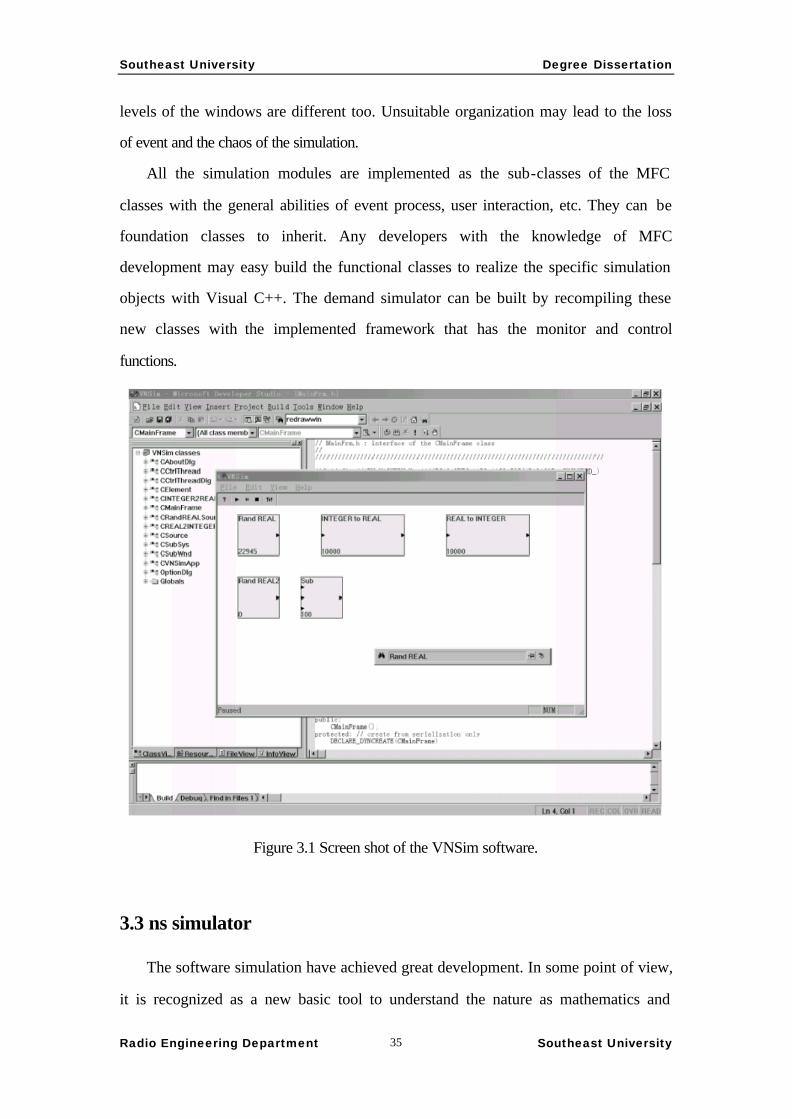
Figure 3.1 Screen shot of the VNSim software.
3.3 ns simulator
The software simulation have achieved great development. In some point of view,
it is recognized as a new basic tool to understand the nature as mathematics and
Southeast University Degree Dissertation
Radio Engineering Department Southeast University 36
laboratory11. There are more than 150 kinds of simulation systems for special or
general purpose, covering all kinds of hardware platforms. They are implemented in
C/C++, Fortrain, Java, Tcl, etc. Some general purpose event-driven simulation
frameworks are also available, e.g. the GPSS/H
(http://www.wolverinesoftware.com/h1.htm). During decades of the development of
the network, many simulation systems were also developed to satisfy the research
requirement. For example, the BONeS from Candence for UNIX (SunOS) system, the
Opnet for PC/Windows and the ns simulator for multiple platforms are common to
see. These simulators have the following common features:
(1) Suitable for high level network simulation. It is convenient for users to build
the simulation scenes and environments. The setup of the simulation scene is similar
to the actual network system, which makes it easy to understand and share.
(2) The modularized implementation supports module reuse and redevelopment
to keep up with the fast development and variation of the network system and
research. Based on them, many validated work that realized specific and detailed
network technologies are available.
(3) Support standard input/output format to make it is possible to exchange data
between different software.
(4) Rich visual tools for synthetic analysis.
3.3.1 Introduction
The Opnet and BONeS that we mentioned above are all commercial software
with high price. It is not affordable by many academic researches. So the free and
open source ns simulator is adopted in this paper.
The ns Network simulator has been developing since 1989 under the cooperation of
the Xerox PARC and network research group (NRG), Lawrence Berkeley National
Laboratory, ICSD, UC Berkeley. During decades of development, many extensions
from different research organizations such as MIT and CMU are converged.
Especially, the extension from Monarch Group of CMU makes the ns applicable to
the wireless environments including wireless local area network (WLAN) (IEEE
Southeast University Degree Dissertation
Radio Engineering Department Southeast University 37
802.11), multi-hop ad-hoc network, wired and wireless mixed network and Mobile IP.
This software is free and open source software and widely used in academic
communities. Currently, there are 28 projects in 7 types of subjects using the ns in the
reaseach according to its web site12. Further developments for new versions and
extensions are keep going. For example, the Parallel Distributed Network Simulator
(PDNS) project in Georgia Tech. U.S. brings a powerful future to the ns.
3.3.2 How to get the ns
The ns used in this paper was fetched from the official web site of the ns in UC
Berkeley (http://www-mash.cs.berkeley.edu/ns). The version is 2.1b6 that is released
on Dec.19, 2000. The document referenced in this paper is the one released on Fed.25,
2000. Most of the software that is needed to install, compile and development can be
downloaded from this site. Otherwise, some optional tools and documents need to be
retrieved separately. They are the object-oriented extension to the TCL language,
OTCL (ftp://ftp.tns.lcs.mit.edu/pub/otcl), Tcl/Tk language tools (http://www.scriptics.
com), etc.
The ns is a open project. Any extended modules developed by the users can be
handed over to the VINT group who is the current ns project maintainer if the users
feel like to share the work with the whole community. The extension may be
integrated to the new version of the ns simulator.
3.3.3 Installation on Linux
According to the experience of the VNSim development, we realized that the
windows 98/95 platform is not stable enough for the research. Averagely, the system
will down for every 72 hours when the simulation is running. Although the ns can be
compiled on the windows system, the native development environment is UNIX like
and the porting to windows is not perfect. Considering these factors, we choose the
platform of GNU Linux operation system on Intel x86 PC. After evaluated 3 types of
Linux distributions, Slackware 4.0, Turbo Linux 3.0, RedHat 6.1, we chose the last
one according to the compilation and runtime performance of the ns. Specifically, the
Southeast University Degree Dissertation
Radio Engineering Department Southeast University 38
platform is a PC compatible machine with a Pentium Ⅱ 333 MHz CPU, 64 MB
Memory, 4.3 + 8.2 GB IDE hard drivers, RedHat Linux 6.1, Kernel 2.2.12, GNU gcc
C++ compiler version 2.91.66, Xfree86 3.3.5, Kdevelop C++ integrated development
environment version 0.3.1. This machine also acts as a simulation server to provide
remote service access to the ns for the other research project through the X Windows
system.
There is a bug caused by a POSIX constant definition in ns version 2.1b5. We
made a patch and it is confirmed by the version 2.1b6 after two month. The all- in-one
package of the ns version 2.1b6 can be compiled 13 successfully without any
modification on the environment described above. The details can be refereed to the
documents of the software. And all the development for this project are finished in
this environment.
3.3.4 Analysis to the design of the ns
After the compilation and installation, the ns occupied about 200MB disk space.
The source codes include 814 C++ files and 1003 TCL/OTCL files. Since the
development is still in progress, the details of the analysis described here may be
exact to the very version only.
The ns simulator has an entire object-oriented design. It is very interesting that it
includes an object-oriented implementation of the TCP/IP protocol stack. The core
structure is implemented in C++ and the OTCL engine is embedded to make the
OTCL language as a scripting language to extend the system14. OTCL (MIT’s Object
Tool Command Language) is the object-oriented extension to the TCL language. The
TCL language is a kind of interpretative language. The grammar is very simple and
easy to study. It’s very suitable to embed to the software systems to provide a
scripting mechanism to extend the system without modifications to the core part. In
the ns simulator, OTCL language is used for the following purposes:
(1) To connect the C++ classes to make up the complete program.
(2) Some network simulation components are programmed by the combination of the
there two languages. The part that needs to be modified frequently in the simulation

Southeast University Degree Dissertation
Radio Engineering Department Southeast University 39
can be implemented in OTCL. And the relative fixed part that requires complicated
computation and high performance should be implemented in C++.
(3) To provide the user interface. Actually, a simulation scene description is a piece of
OTCL codes. The network structure, the data traffic, the control and monitoring of the
simulation are all OTCL statements. The whole ns simulator behaves like an extended
OTCL interpreter.
The ns simulator is completely object-oriented. So the analysis starts with the
class view.
An OTCL program being a simulation description is input into the ns simulator. It
describes the network structure by connecting the classes that represent the actual
network elements. The simulator interprets it and the simulation goes. In the runtime
of a simplest simulation job, the existence of the objects in the memory is like what
the Figure 3.2 illustrates.
Figure 3.2 The object layout in the memory for a simplest simulation
The two-way arrows represent the procedure of the control commands for the
software. The thick one-way arrows are the data flow in the software layer. The thin
one-way arrows represent the network transmission flow in the simulation view.
In every simulation job, there is only one global Simulator object. It controls the
Southeast University Degree Dissertation
Radio Engineering Department Southeast University 40
whole simulation.
Class Application is the representation of the application layer of the network. It
generates the traffic and consumes it. Classes Agent is the representation of the
protocol stack. It can be understood as the protocol software in the hosts. Class Node
is the presentation of all kinds of network nodes in the network, e.g. all kinds of
hardware, computer, switch, router, etc. The Application, Agent, Node should work
together. What connects them is the class Link. Link represents the data link. It is the
combination of a group of software modules, the queues with all kinds of drop
algorithms, transmission delay and error generators, etc.
The simulation users need only to set the connections between Agents when they
want to describe the data transmission in the network. Once the connections between
the Nodes and Links are set, they are transparent to the data transmissions. It is same
to the actual network that after the network is built, the data will be routed and
transferred according to the protocols and the hardware configurations. The ns
implemented many kinds of routing algorithms to decide the physical paths made up
with Nodes and Links.
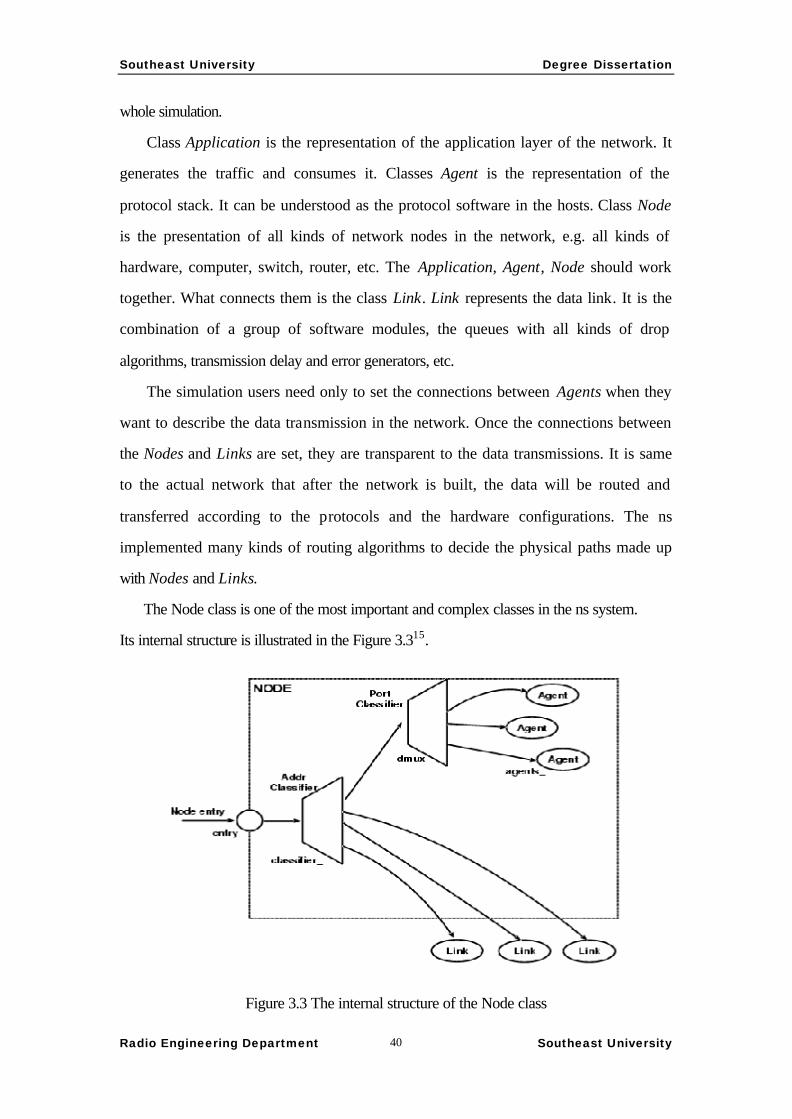
The Node class is one of the most important and complex classes in the ns system.
Its internal structure is illustrated in the Figure 3.315.
Figure 3.3 The internal structure of the Node class
Southeast University Degree Dissertation
Radio Engineering Department Southeast University 41
The classifier in above figure is used to route the data. What needs explanation is
that in the wireless simulation, the Nodes are not connected by Links. The special
wireless Nodes with the extra Link Delay, Address Resolution Protocol (ARP),
Interface Queue, Media Access Control (MAC) Layer (IEEE 802.11), Network
Interface, Radio Propagation Model and the Antenna Modules are connected to each
other directly.
The Scheduler is a global class to schedule the events for the whole system. There
are several schedule mechanism to be selected. The basic principle is to keep event
that will occur most early in the head of the queue. The most important type of the
events is the Packet in the ns. The Packet represents the transmission data unit, e.g.
the IP packet and ATM cells. Under the scheduling of the Scheduler, data can be
transferred from source to destination with accurate delay and errors. Generally, the
data described in the Packets flows through the path illustrated in the Figure 3.2, but
when the delay should be generated, the Packets will be passed to the Scheduler to
schedule in the queue. At the exact moment, the Packets will be moved out of the
queue and dispatched to the next node in the appropriate route.
3.3.5 Use of the ns
The main way to use the ns is the simulation description file. The file is a piece of
OTCL program with appropriate procedures to create the Scheduler, Notes, Links,
Agents and Applications, to generate the desired trace output, to monitor the interested
variables and to start and stop the simulation. The ns documents include detailed
guide to write such description files.
The simulation generates two types of output files. One is the log of the
information of all the events including start time, finish time, etc. The Network
Animator (NAM) tool in the ns package can replay the whole process of the
simulation according to this event log. Every packet can be traced by this way. The
other type of output is the file to record the variation of the given variables. These
variables are always the key parameters of the algorithms or protocols to study. Such
files can be analyzed by graph with the x-graph tool. Most of the graphs in this paper

Southeast University Degree Dissertation
Radio Engineering Department Southeast University 42
are generated by these tools.
Figure 3.4 Screenshot of the NAM tool
3.3.6 Extending the ns
The major method to extend the ns is to use OTcl or C++ language to inherit the
existing classes of the ns to implement new classes and recompile the software. Of
course, the OTCL classes need not recompilation. The details will be discussed in the
next section to discuss the implementation of the next generation ATM in the ns. The
trunk of the class tree in the ns is illustrated in the Figure 3.5.
Figure 3.5 some important classes and their inherited relationships in the ns

Southeast University Degree Dissertation
Radio Engineering Department Southeast University 43
3.3.7 Shortcomings of the ns
One shortcoming comes from the character of the free software. All the work
from compilation to configuration has to be done by the users before it can do the
desired simulation. And it is a big deal to do the development without technical
supports and satisfying documentations.
The other shortcoming is its user interaction mechanism. All the controls are
defined in the description file in advance. When the simulation starts, it cannot be
interrupted and resumed. It is very inconvenient when the algorithm and protocol still
need frequent modifications in the research or during the debug of the new extensions
to the ns and the large-scale network scene. The solution to overcome this
disadvantage may be the modification to the Scheduler to make the event scheduling
can be interrupted and resumed just as what we did in the VNSim.
3.4 Extensions to the ns and the realization of the next
generation ATM protocol
We have tried to extend the ns based on the version 2.1b5 and 2.1b6. More than
10,000 line of codes have been developed to implement the core of the next
generation ATM protocols for the ns on the version 2.1b6 finally.
3.4.1 New ATM Cell
One of the characteristics of the ns is the Packet mechanism. Because it is not
necessary to process the payload data of the data unit, only the header structure is
worth considering. Different type of data unit has its own data structure to describe
the organization of the whole unit. There is a list to carry such structures that
describes this packet for different protocols. For example, the Packet to represent a
TCP segment maintains a structure list that includes at east the IP structure and TCP
structure. So the packet can be appropriately interpreted in both TCP and IP layer.
The new protocol is defined here, so the structure to represent the new ATM cell
should be defined. Considering the research aims, we choose the following fields to
Southeast University Degree Dissertation
Radio Engineering Department Southeast University 44
be described in the Packet. They are the VPI, VCI, CLP, GSN, FIN, DT,
MICROCELLNUM and SEND_TIME. Some of them are just for the simulation, not
exist in the actual protocol.
3.4.2 Implementation of the new Agents
The major work of the development is to implement the new Agents.
There are two important methods in the Agent class. They are recv and sendmsg
methods. The recv is invoked by the Scheduler to pass the Packets and flags. Through
this method, Agents accept the data to process with the appropriate protocol. The
actions include feedback for retransmission or transferring the data to he application
layer. The sendmsg method is called by the application layer indirectly. It accepts a
number that means the length of the data block in byte.
In this project, 3 major Agents were implemented. They are WLATMAgent to
realize the protocol stack for terminator, WLATMServer to realize the protocol stack
that can handle multiple VC in terminator and WLATMSwitcher to realize the
protocol stack for switch. In these Agent classes., the work of the AAL is done in their
sendmsg method.
It is different to the implementation of the TCP/IP protocol stack. The TCP/IP
packet can be sent at every moment if it wants. That is to say, the sendmsg method of
the TCP/IP Agents may call the interface method of the Node class directly. But the
transmission mechanism of ATM is different. The slots of the cells are fixed. The
ATM cell cannot occur in the link at any moment. In order to simulate this, extra
work should be done in the sendmsg method. The ATM cells are not passed to the
Nodes simply. They should be cached in the buffer. On the other hand, a timer should
be set with the interval that is calculated according to the cell length and link
bandwidth. The timer fetches the cells from the buffer and passes them to the Nodes.
The WLATMServer class to handle multuple VC is defined also for this reason. In the
design of the ns, an Agent should handle only one connection. It needs not to know
the information of the lower layer. But the Agents for ATM should get the
information of bandwidth to calculate the interval for the timers. That is a way to
Southeast University Degree Dissertation
Radio Engineering Department Southeast University 45
overcome the limit of the connectionless nature of the underlying mechanism of the
ns simulator.
In the WLATMAgent and WLATMServer classes, the backward feedback
mechanism for the retransmission is implemented. And a timer is set in the destination
to resend the feedback when the desired response doesn’t arrive over-clocked. This is
for the situation that the link is so congested that the feedback is dropped and the
source cannot see the FIN flag. Without this mechanism, both sides will fall into
endless wait in such case.
Because there is the network based traffic control in the switch, there is no need
to implement an end-to-end flow control. This makes the Agents of the ATM protocol
much simple than TCP.
3.4.3 Other modifications
For the special requirement of our research, some Application subclasses are also
developed. They are the FTP, WebServer, WebClient and G.729 classes.
Another effort to implement the connection-oriented network on the ns is to add a
call method in the Scehduler class to consult the parameters and establish the
connection before the traffic is generated.
In order to make the ns know the new protocol, some constants and definitions
should be added and modified. It is discussed in the documents of the ns.
If the C++ classes want to be seen by the OTCL, a “bind” must be done. Every
C++ classes should have a “shadow” class which acts as a stub to the OTCL space. It
exposes the members and methods to be accessed by the OTCL.
The major part of the work is summarized in Figure 3.6
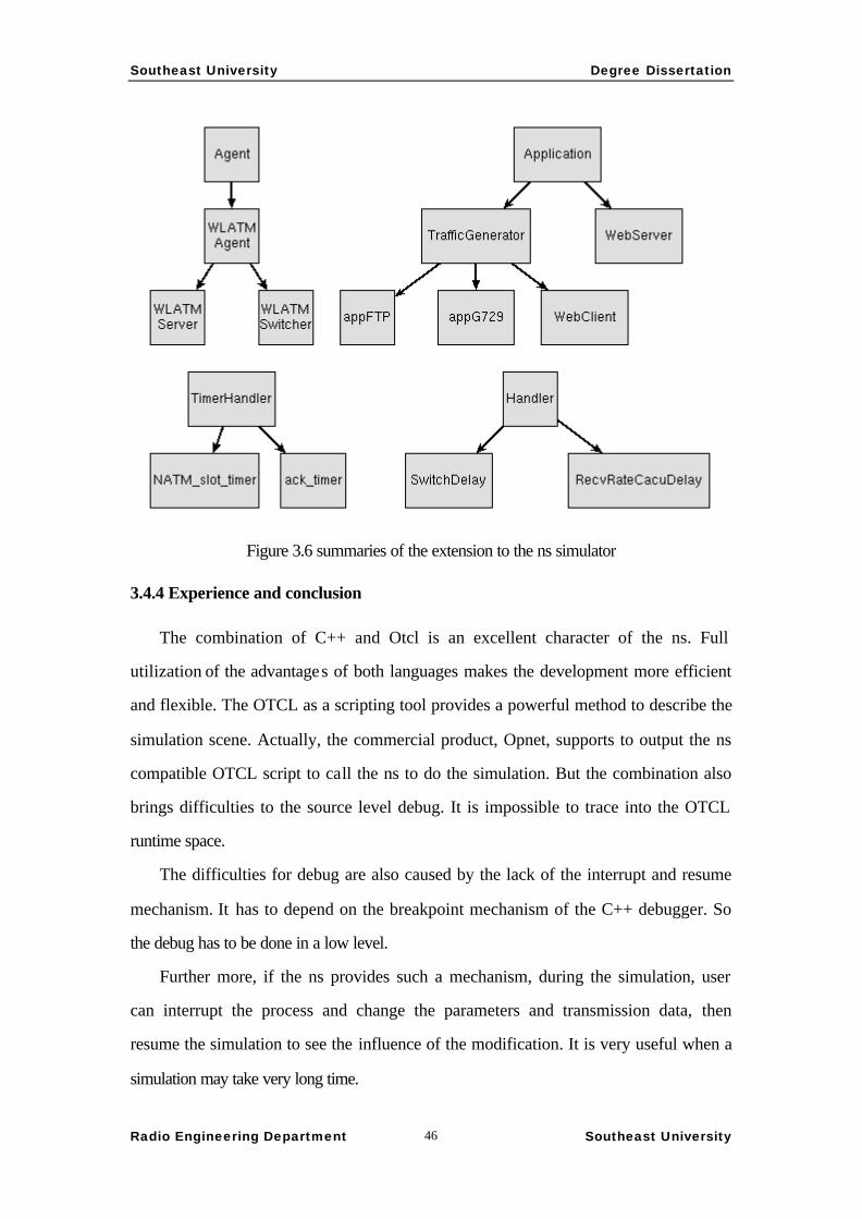
Southeast University Degree Dissertation
Radio Engineering Department Southeast University 46
Figure 3.6 summaries of the extension to the ns simulator
3.4.4 Experience and conclusion
The combination of C++ and Otcl is an excellent character of the ns. Full
utilization of the advantages of both languages makes the development more efficient
and flexible. The OTCL as a scripting tool provides a powerful method to describe the
simulation scene. Actually, the commercial product, Opnet, supports to output the ns
compatible OTCL script to call the ns to do the simulation. But the combination also
brings difficulties to the source level debug. It is impossible to trace into the OTCL
runtime space.
The difficulties for debug are also caused by the lack of the interrupt and resume
mechanism. It has to depend on the breakpoint mechanism of the C++ debugger. So
the debug has to be done in a low level.
Further more, if the ns provides such a mechanism, during the simulation, user
can interrupt the process and change the parameters and transmission data, then
resume the simulation to see the influence of the modification. It is very useful when a
simulation may take very long time.
Southeast University Degree Dissertation
Radio Engineering Department Southeast University 47
In general, the ns simulator is a reliable and flexible system for the network
simulation. And its open architecture is an ideal development platform to implement
specialized functions to evaluate new ideas.
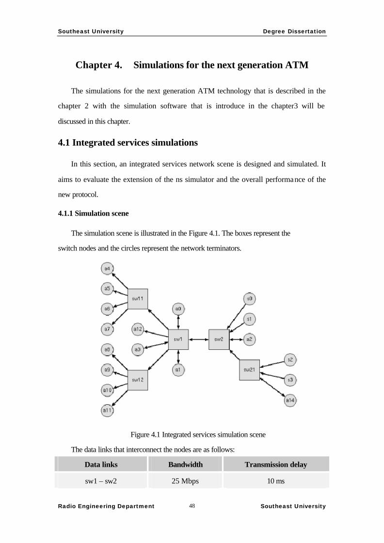
Southeast University Degree Dissertation
Radio Engineering Department Southeast University 48
Chapter 4. Simulations for the next generation ATM
The simulations for the next generation ATM technology that is described in the
chapter 2 with the simulation software that is introduce in the chapter3 will be
discussed in this chapter.
4.1 Integrated services simulations
In this section, an integrated services network scene is designed and simulated. It
aims to evaluate the extension of the ns simulator and the overall performance of the
new protocol.
4.1.1 Simulation scene
The simulation scene is illustrated in the Figure 4.1. The boxes represent the
switch nodes and the circles represent the network terminators.
Figure 4.1 Integrated services simulation scene
The data links that interconnect the nodes are as follows:
Data links Bandwidth Transmission delay
sw1 – sw2 25 Mbps 10 ms

Southeast University Degree Dissertation
Radio Engineering Department Southeast University 49
sw11,sw12 – sw1 1.536 Mbps 10 ms
a12 – sw1 1.536 Mbps 25 us
a0,a1,a3 – sw1 56 Kbps 25 us
s0,s1 – sw2 40.704 Mbps 25 us
a2 – sw2 56 Kbps 25 us
sw21 –sw2 1.536 Mbps 10 ms
s2,s3 – sw21 40.704 Mbps 25 us
a14 – sw21 56Kbps 25 us
a4 to a7 – sw11 1.536 Mbps 25 us
a8 to a10 – sw12 1.536 Mbps 25 us
a11 – sw12 56 Kbps 25 us
The traffic of the simulation is as follows:
1. Real-time service, G.729 compressed voice, bi-directional transmission.
Simulation time is from 0.1s to 4.9s
a1 <-> a1, a2 <-> a3, a14 <-> a11
2. WWW browse, asymmetrical bi-directional bursty data transmission. Simulation
time is from 0.5s to 14.5s
a4,a8 <-> s0; a5,a9 <-> s2
3. FTP traffic, unidirectional endless data transmission, simulated form 0.5s to 10s
a6, a12 <- s1; a7, a10 <-s3
The bandwidth allocation policy in the switches is (a) fixed 12.5 Kbps for every
type 1 connection, (b) guaranteed 8 Kbps for each type 2 connection and (c) 200 Kbps
guaranteed for each type 3 connection. Each link reserves 10% bandwidth. The
remaining bandwidth is ABR bandwidth to be shared within the type 2,3 connections.
4.1.2 Simulation results
Analysis of transmission delay
The analyses focus on the delays on the destinations to evaluate the supports of
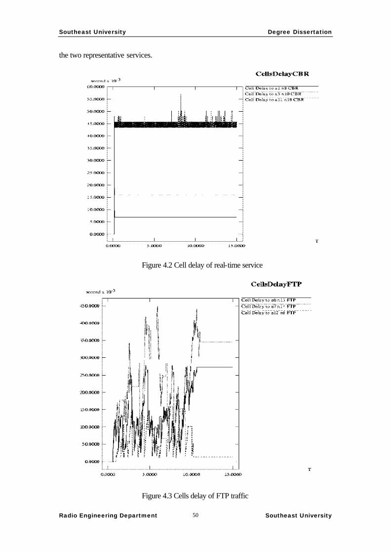
Southeast University Degree Dissertation
Radio Engineering Department Southeast University 50
the two representative services.
Figure 4.2 Cell delay of real-time service
Figure 4.3 Cells delay of FTP traffic

Southeast University Degree Dissertation
Radio Engineering Department Southeast University 51
Figure 4.3 Cells delay of Web browse traffic
This scene tries to represent the wide area network (WAN) situation. The
maximum link delay is over 30 ms. The switching delays are all 100 us in the
switches.
Investigating Fig.4.2, 3 curves illuminate the cells delay of G.729 voice data
flows through different numbers of switches and the network backbone. When
through only one switch, the delay is below 10 ms; through 2 switches, it raises to
15ms. The link transmission delay is the major part. The switches in the path are
relative low load, so the delay jitter is quite small. These two situation covers about
4000 KM physical distances. Plus the voice coding time smaller than 15 ms, it is easy
to satisfy the limit of 25 ms. The echo canceller is eliminated. The highest curve
describes the delay in the connection through three switches, over 6000 KM. Some of
the switched are very high load, so the delay jitter is larger. Considering the speed,
only few CBR connections are set in the simulation. To keep necessary efficiency, the
macro cell has to linger in the buffer of the edge switch for a long time, thus brings a
relatively high delay jitter. In real case, every edge switches serves a lot of CBR

Southeast University Degree Dissertation
Radio Engineering Department Southeast University 52
connections. It takes little to fill up a macro cell, thus results in a smaller delay jitter.
FTP and Web are another typical type of traffic. The major difference between
them is the length of the data blocks. Comparing to CBR service, the delay is larger.
The major factor of the delay is not the link delay but the switching delay. Further
more, the delay jitter is large. The main reason that causes this is the queuing in
switches. This is acceptable because the requirement for these parameters is relative
low.
Efficiency analysis
The investigation is focused on the switching nodes.
What this model considers is the wired wide area network. The error rates should
be low. What causes the cells to be dropped is mainly the congestion that makes the
buffer overflows in switches. In the simulation, the queue length in every switch is
100 cells. All the links share a common buffer.
Figure 4.5 Queue length in the switches

Southeast University Degree Dissertation
Radio Engineering Department Southeast University 53
Figure 4.6 Dropped cells
Figure 4.7 Byte Passes

Southeast University Degree Dissertation
Radio Engineering Department Southeast University 54
Fig.4.5 shows the queue length of each witch. Fig 4.6 describes the drop of the
cells. The drop policy is simple queue tail drop. It is obvious that the sw1 and sw21
are the bottlenecks. The queue length falls down after about 11s because the FTP
traffic is terminated at 10s.
Figure 4.7 shows the transmission efficiency in each switch. Two groups of
curves are the total number of bytes and bytes of the pure payload of the data cells.
We can calculate the overall values after the whole simulation:
Sw1 Sw2 Sw11 Sw12 Sw21
87.37% 70.60% 85.33% 83.44% 90.32%
There are two factors that affect the efficiency. One is the feed up ratio of the
macro cells. The other is the quantity of the resource management cells that is
determined by the congestion situation and the algorithm.
In general, the efficiency is much higher than traditional ATM.
4.2 Wireless network simulation
4.2.1 Summary
One of the aims to study the next generation ATM is to employ the ATM
technology in the wireless environment. Considering the characters of the wireless
and narrow bandwidth wired channel, the new protocol has some special
enhancements. One is to strengthen the head error control. The other is the error
control of the whole cell. The large length of the macro and large cell can carry more
error control information still with relative high efficiency. And the new GSN field
makes it possible to feedback and retransmission. These enhancements may bring the
ATM into the wireless environment.
For the micro cells that mainly dedicate to real-time services, error correction is
enough. There’s no need to retransfer. Because the cell size is quite small, the effect
to the user experience is small. Further more, we are thinking about another
mechanism to make the time insensitive service to be transferred by the macro cell
structure. So the retransmission unit can be the micro cell. The transmission efficiency
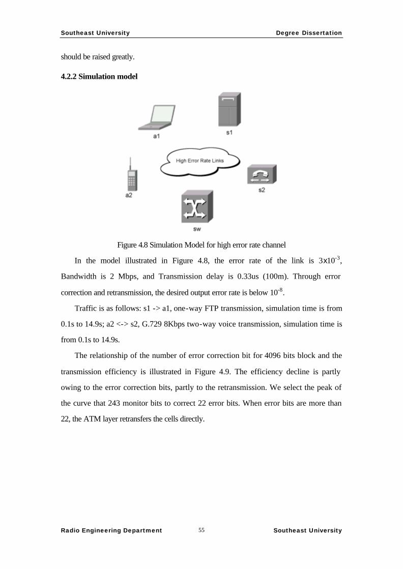
Southeast University Degree Dissertation
Radio Engineering Department Southeast University 55
should be raised greatly.
4.2.2 Simulation model
Figure 4.8 Simulation Model for high error rate channel
In the model illustrated in Figure 4.8, the error rate of the link is 3x10⁻³,
Bandwidth is 2 Mbps, and Transmission delay is 0.33us (100m). Through error
correction and retransmission, the desired output error rate is below 10-8.
Traffic is as follows: s1 -> a1, one-way FTP transmission, simulation time is from
0.1s to 14.9s; a2 <-> s2, G.729 8Kbps two-way voice transmission, simulation time is
from 0.1s to 14.9s.
The relationship of the number of error correction bit for 4096 bits block and the
transmission efficiency is illustrated in Figure 4.9. The efficiency decline is partly
owing to the error correction bits, partly to the retransmission. We select the peak of
the curve that 243 monitor bits to correct 22 error bits. When error bits are more than
22, the ATM layer retransfers the cells directly.

Southeast University Degree Dissertation
Radio Engineering Department Southeast University 56
Figure 4.9 Monitor bits to transmission efficiency
In 128 bits micro cell, 16 monitor bits are set to correct 2 error bits and check
more.
4.2.2 Simulation result
Delay analysis
Figure 4.10 Real-time service delay
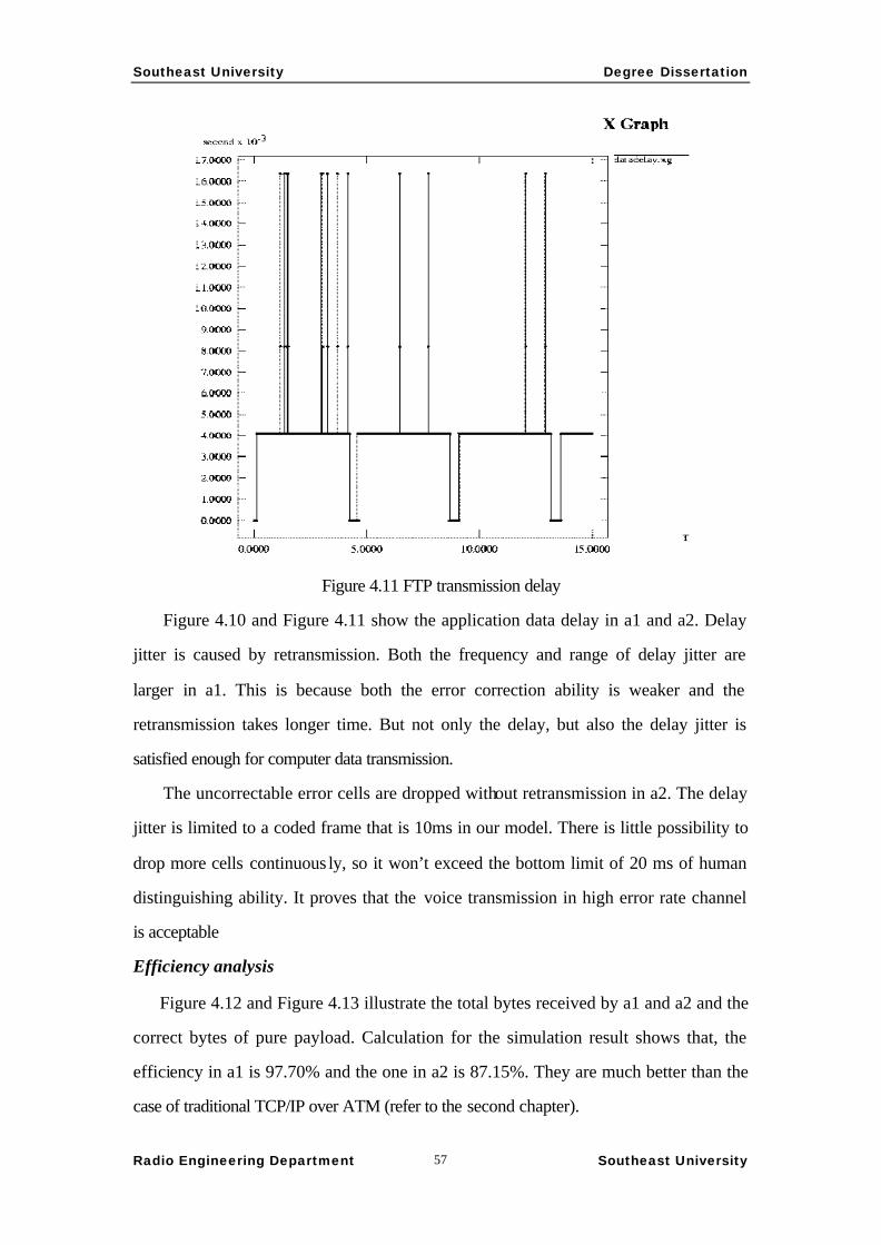
Southeast University Degree Dissertation
Radio Engineering Department Southeast University 57
Figure 4.11 FTP transmission delay
Figure 4.10 and Figure 4.11 show the application data delay in a1 and a2. Delay
jitter is caused by retransmission. Both the frequency and range of delay jitter are
larger in a1. This is because both the error correction ability is weaker and the
retransmission takes longer time. But not only the delay, but also the delay jitter is
satisfied enough for computer data transmission.
The uncorrectable error cells are dropped without retransmission in a2. The delay
jitter is limited to a coded frame that is 10ms in our model. There is little possibility to
drop more cells continuous ly, so it won’t exceed the bottom limit of 20 ms of human
distinguishing ability. It proves that the voice transmission in high error rate channel
is acceptable
Efficiency analysis
Figure 4.12 and Figure 4.13 illustrate the total bytes received by a1 and a2 and the
correct bytes of pure payload. Calculation for the simulation result shows that, the
efficiency in a1 is 97.70% and the one in a2 is 87.15%. They are much better than the
case of traditional TCP/IP over ATM (refer to the second chapter).

Southeast University Degree Dissertation
Radio Engineering Department Southeast University 58
Figure 4.12 Voice transmission efficiency
Figure 4.13 FTP transmission efficiency
Southeast University Degree Dissertation
Radio Engineering Department Southeast University 59
CONCLUSION
ATM has not achieved its design target, which is to use one standard method to
replace various incompatible network technologies. The reason lies on the fact that it
can support neither data service, nor low-bit-rate voice efficiently. Upgrading is the
only way that ATM could keep its existence.
This paper proposes a novel architecture for the next generation ATM, which
adds a GSN field in the head of a prolonged ATM cell to reinforce the end-to-end
error control ability, adopts micro cell outside the backbone networks to enhance the
ability to support low-speed real-time service. Our proposal also considers the need
for wireless environment.
In order to do the research, we study the network software simulation. And the
necessary simulation tools are developed. Under the help of these tools, two typical
wired and wireless models are simulated.
The analysis and simulation results show that, such a modification to the existing
ATM protocol can overcome the shortcomings of it and upgrade its ability to support
more services.

Southeast University Degree Dissertation
Radio Engineering Department Southeast University 60
REFERENCES
1 SHIDUAN SHENG, Integrated Services Digital Network, People’s Post and
Telecommunication Publish House, Beijing, P.R.China, June, 1995.
2 MINGTIAN ZHOU, WENYONG WANG, TCP/IP Principle and Technology,
Tsinghua University Press, Bejing, P.R.China, April,1996.
3 HUILING HZAO, ATM, Frame Relay, IP Technology and Application, Publishing
House of Electronics Industry, Beijing, P.R.China, Oct.1998.
4 CHARLES D.CRANDOR, An Implementation Model for Connection-Oriented
Internet Protocols, A Thesis Presented to the Server Institute of Washington
University in partial fulfillment of the requirements for the degree of MASTER OF
SCIENCE, May 1992 Saint Louis, Missouri.
HTTP://www.ccrc.wustl.edu/pub/chuck/psgz/coip-thesis.ps.gz
5 GURU PARULKAR、HARI ADISESHU, Emerging Internetworking Architecture
and Protocols, Applied Research Laboratory and Computer and Communication
Res.Center, Department of Computer Science, Washington University in St.Lousis.
HTTP://www.arl.wustl.edu/~guru/IP-atm.ps
6 ZHEN YANG, HOUJIE BI, New method to improve the system performance by
reducing the adaptation delay of voice service in ATM network, Communication
Proceeding, Vol.9 No.10, 1998
7 RICHARD V.COX, Three New Speech Coders from the ITU Cover a Range of
Applications, IEEE Communication Magazine. September 1997
8 KEVIN THOMPSON, GREGORY J.MILLER, RICK WILDER, Wide-Area
Internet Traffic Patterns and Characteristics, IEEE Network. November/December
1997
9 YIHAN LI, XIAOKANG LIN, ZHISHENG NIU, Narrow-band ATM,
Telecommunication Technology, No.2, Vol. 13, Feb.1997
10 ZHIYONG ZHANG, RUIZHEN LIU, ZUING YANG, Mastering MATLAB,
Southeast University Degree Dissertation
Radio Engineering Department Southeast University 61
Beijing Aviation and Spaceflight University Press, Beijing, P.R.China, Aug.1997.
11 JOHN L. CASTI, Would-Be Worlds: How Simulation Is Changing the Frontiers of
Science, New York, NY: John Wiley and Sons, 1997
12 SANDEEP BAJAJ, LEE BRESLAU, DEBORAH ESTRIN,KEVIN FALL,SALLY
FLOYED,PADMA HALDAR,MARK HANDLEY,AHMED HELMY,JOHN
HEIDEMANN,POLLY HUANG,SATISH KUMAR,STEVEN MCCANNE,REZA
REJAIE,PUNEET SHARMA,KANNAN VARADHAN,YA XU,HAOBO YU, and
DANIEL ZAPPAL, A improving simulation for network research. Technical Report
99-702b,University of Southern California, March 1999.(revised September 1999).
13 XIANGKE LIAO, Jun LUO, QINGBO TANG, Linux Maintenance and
Development, People’s Post and Telecommunication Publishing House, Beijing,
China, Sep.1999
14 DAVID WETHERALL, CHRISTOPHER J LINDBLAD, Extending Tcl for
Dynamic Object-Oriented Programming, Proceedings of the Tcl/Tk Workshop
'95,Toronto, July 1995.HTTP://www.tns.lcs.mit.edu/publications/tcltk95.djw.html
15 KEVIN FALL, Editor, KANNAN VARADHAN, Editor, ns Notes and
Documentation, February
25,2000.HTTP://www-mash.cs.berkeley.edu/ns/ns-documentation.html


![Optimistic Parallel Simulation of TCP/IP Over ATM … · Optimistic Parallel Simulation of ... 4 Implementation of simulation models ... and the Telesim project [31]. Experiments](https://img.pdfslide.net/doc/110x75/5ad560877f8b9a5d058d18be/optimistic-parallel-simulation-of-tcpip-over-atm-parallel-simulation-of-.jpg)