Embed Size (px)
Citation preview

Study on influence of the new CoDeSys V3.0 on the existing CoDeSys discipline of the Mind8 Engineering
Center
HUGO FILIPE DA SILVEIRA TEIXEIRA PEREIRA (Bacharel em Engenharia Electrotécnica)
Dissertação para a obtenção do grau de Mestre em
Engenharia Electrotécnica – ramo de Automação e Electrónica Industrial
Orientador (es): Dipl.-Ing. Raphael Buck Ph.D. Acácio Galhardo
Júri: Presidente: Vogais:
Mês de Ano

I Acknowledgment
2
I Acknowledgment
I want to thank to Ph.D. Acácio Galhardo for the great willingness to accept me as my
I.S.E.L. tutor. I want to thanks also to Prof. Ricardo Luis, for guide me in the Erasmus
process. Thank you for all your efforts.
I specially want to thank to my German tutor, Dipl.-Ingenieur Raphael Buck, for all the help
he gave me and most of all for never make me feel I was alone. Another special thanks to
Harro Höfliger team. They always make me feel like I was at home, and most of all they had
so many patience speaking to me always in English because they know in that time my
German was not so good. They are Mr. Scheub, Mr. Weller and Mr. Haupt from
development department. I only have good memories from them.
Special thanks for my friend and college Rui Figueiredo for all the friendship and company
he gave to me, after all, we are the only two Portuguese in the Stuttgart University Campus.
Finally, I want to most specially thanks to my parents and my girlfriend, Carla, for all the
support in this time that I have been away.
Stuttgart, July 2012
II Theme
3
II Theme

III Table of Contents
4
III Table of Contents
I Acknowledgment .......................................................................................... 2
II Theme ............................................................................................................ 3
III Table of Contents ......................................................................................... 4
IV Abbreviations ................................................................................................ 6
1 Abstract ......................................................................................................... 7
2 Basics ............................................................................................................ 8
2.1 Packaging Machinery ..................................................................................... 8
2.2 PLC – Programmable Logic Controller ......................................................... 11
2.3 Standard IEC 61131-3 .................................................................................. 12
2.3.1 Configuration, Resources and Tasks ............................................................ 14
2.3.2 Programming Languages .............................................................................. 16
2.4 PLCopen ....................................................................................................... 21
2.5 Eplan Engineering Center (EEC) .................................................................. 23
3 Traffic Light Sample ................................................................................... 24
3.1 Creation of CoDeSys Version 2 Project ........................................................ 25
3.2 Project XML Output – Eni-Server .................................................................. 31
3.3 Import of the Traffic Light Sample into CoDeSys Version 3 and adding of an
object oriented function block ....................................................................... 33
3.4 XML Comparison of CoDeSys Version 2 and Version 3 ............................... 44

III Table of Contents
5
4 Analysis of Epas-5 XML-Import/Export-Scheme ...................................... 47
4.1 Export/Import PLCopenXML Tool ................................................................. 48
4.2 Comparison of Schemes ............................................................................... 49
5 Creation of the Eplan Engineering Center Model .................................... 69
5.1 Mechatronic Architecture Library Creation .................................................... 70
5.2 Epas-5 Architecture Library Creation ............................................................ 71
5.3 Mechatronic Construction Library Creation ................................................... 73
5.4 Road Project Construction ............................................................................ 94
6 Summary of Results ................................................................................. 100
7 Future Prospects ...................................................................................... 103
V List of Figures ........................................................................................... 104
VI List of Tables ............................................................................................. 108
VII References ................................................................................................ 109
VIII Appendix ................................................................................................... 110

IV Abbreviations
6
IV Abbreviations
Abbreviation Meaning
FDB Function Block Diagram
SFC Sequential Function Chart
LD Ladder Diagram
ST Structure Text
IL Instruction List
IEC International Electrotechnical Commission
PLC Programmable Logic Controller
CPU Central Processor Unit
POU Program Organization Unit
XML Extensible Markup Language
EEC Eplan Engineering Center
I/O Inputs/Output
TC Technical Committees
HH Harro Höfliger
OOP Objects Oriented Programming

1 Abstract
7
1 Abstract
CoDeSys "Controller Development Systems" is a development environment for
programming in the area of automation controllers. It is an open source solution completely
in line with the international industrial standard IEC 61131-3. All five programming
languages for application programming as defined in IEC 61131-3 are available in the
development environment. These features give professionals greater flexibility with regard
to programming and allow control engineers have the ability to program for many different
applications in the languages in which they feel most comfortable.
Over 200 manufacturers of devices from different industrial sectors offer intelligent
automation devices with a CoDeSys programming interface. In 2006, version 3 was
released with new updates and tools.
One of the great innovations of the new version of CoDeSys is object oriented
programming. Object oriented programming (OOP) offers great advantages to the user for
example when wanting to reuse existing parts of the application or when working on one
application with several developers. For this reuse can be prepared a source code with
several well known parts and this is automatically generated where necessary in a project,
users can improve then the time/cost/quality management.
Until now in version 2 it was necessary to have hardware interface called “Eni-Server” to
have access to the generated XML code. Another of the novelties of the new version is a
tool called Export PLCopenXML. This tool makes it possible to export the open XML code
without the need of specific hardware. This type of code has own requisites to be able to
comply with the standard described above. With XML code and with the knowledge how it
works it is possible to do component-oriented development of machines with modular
programming in an easy way. Eplan Engineering Center (EEC) is a software tool developed
by Mind8 GmbH & Co. KG that allows configuring and generating automation projects.
Therefore it uses modules of PLC code. The EEC already has a library to generate code for
CoDeSys version 2. For version 3 and the constant innovation of drivers by manufacturers,
it is necessary to implement a new library in this software. Therefore it is important to study
the XML export to be then able to design any type of machine. The purpose of this master
thesis is to study the new version of the CoDeSys XML taking into account all aspects and
impact on the existing CoDeSys V2 models and libraries in the company Harro Höfliger
Verpackungsmaschinen GmbH. For achieve this goal a small sample named “Traffic light”
in CoDeSys version 2 will be done and then, using the tools of the new version it there will
be a project with version 3 and also the EEC implementation for the automatically
generated code.

2 Basics
8
2 Basics
2.1 Packaging Machinery
Packaging is the technology for protection and storage of products. To do the packaging of
products fast and with high reliability usually very sophisticated machines are used often
with the latest know-how and technology.
The company Harro Höfliger Verpackungsmaschinen GmbH is exclusively dedicated to the
design and construction of machinery for packaging production primarily for the medical
market. The technology introduced on these machines makes them able to produce any
product for this sector. To automate these devices the company uses programmable logic
controllers (PLC) from the brand ELAU. This brand was recently acquired by Schneider
Electric Company.
Figure 1 - Machinery for packaging production for the medical sector One of big difficulties that existed in the past in the design of these machines was the
programming of automation devices like drives or cylinders and how this task was
performed. Each PLC programmer used to do his own way of programming which meant
that there was no standardization of code in any of the machines that were produced.
All PLCs were and still are programmed until today in CoDeSys version 2 Software with
Epas-4 (Elau). This is done to ensure that the standard "IEC 61131-3 Program Controllers,
Programming Languages" is fully accomplished.

2 Basics
9
As already mentioned, Harro Höfliger Verpackungsmaschinen GmbH produced machines
in the past without a harmonization of parameters for the programming of their machines.
To improve this situation there was adopted software called "Eplan Engineering Center"
developed by the German company Mind8 GmbH & Co. KG. This software uses libraries of
components based on mechatronic machine segments. These are once developed and
then many times used for the construction of a new model. All the code necessary to
program the machine is drawn into fragments for the various blocks and components, using
hierarchies among them. At the end of construction of the whole new machine, the PLC
code is generated using the CoDeSys library. This library contains all the code for
implementing the specific PLC code of Harro Höfliger.
Today, the Harro Höfliger mechatronic model consists of the disciplines control software,
wiring diagram and software documentation (SDS). In short, libraries with standardized
code fragments corresponding to mechatronic components are created in the software
EEC. The PLC code implementation of a new machine is then not more than joining several
pieces of mechatronic components with included code and adjusting various parameters to
customer defined requirements that will be present on the machine.
Figure 2 – Eplan Engineering Center variant management and configuration

2 Basics
10
Therefore, when creating a code for a new machine, the user does more than build a
machine using a graphical model which contains all the components that constitute it. This
ensures then that all the code is constructed and approved in advance and thereafter is
consistently used the same pattern.
The purpose of this master thesis is to create a new library for the software "Eplan
Engineering Center" so that the code is generated according to the new version 3 of
CoDeSys ( Epas-5 from Elau). Besides of that, all the generated code in version 3 must be
in accordance with the standards of quality of machines produced by the company Harro
Höfliger. The influence on the new code generated by "Eplan Engineering Center" should
also be analyzed; it should be verified that all parameters of IEC 61131-3 are covered.

2 Basics
11
2.2 PLC – Programmable Logic Controller
A programmable logic controller (PLC) or programmable controller is a digital computer
used for automation of electromechanical processes, such as control of machinery on
factory assembly lines, amusement rides, or light fixtures. PLCs are used in many
industries and machines.
Unlike general-purpose computers, the PLC is designed for multiple inputs and output
arrangements, extended temperature ranges, immunity to electrical noise, and resistance to
vibration and impact. Programs to control machine operation are typically stored in battery-
backed-up or non-volatile memory.
A PLC is an example of a hard real time system since output results must be produced in
response to input conditions within a limited time, otherwise unintended operation will
result. [12]
The first PLC was made in the 70´s with a simplified programming language and limited to
meet demand in place of industrial control systems based on relays. Over the years various
functions have been incorporated into the controller, such as treatment of analog variables,
and complex arithmetic algorithms, not limited only to discrete logic (I/O).
Figure 3 – PLC System Overview All PLCs have three physical parts (hardware) for your basic operating: CPU (Central
Processing Unit), memory unit and Inputs and outputs (I/O), all communicating via a bus
communication. The CPU coordinates all tasks and executes the PLC program control
stored in memory.

2 Basics
12
The actual states of the process are monitored and sampled by the drive I/O. All
programming is done through an engineering station (computer) in which the program is
compiled and loaded into the CPU to be stored in memory using local area network (LAN).
The PLC allows monitoring of inputs and outputs in real time using the engineering
workstation, while the program is running.
The company Harro Höfliger uses controllers from the brand Elau with the software Epas-4.
Controllers and software use CoDeSys version 2 interface.
Figure 4 – Elau Programmable Logic Controller
2.3 Standard IEC 61131-3
IEC 61131-3 is a programming language standard, independent and standardized for the
industrial automation sector. This standard was established by the International
Electrotechnical Commission (IEC), an organization of creating global standards at the level
established in 1906 and recognized worldwide by industry standards that elaborate.
Applying a standard programming language has a positive impact on the life cycle of a
software requisite that includes analysis, design, construction, testing (validation),
installation, operation and maintenance. IEC 61131-3 provides support of multiple
languages within one control program. The user / programmer can select the language that
is most suitable for a particular task, thereby increasing his productivity. Ladder Diagram
(LD) and Instruction List (IL) are fairly simple, so appropriate mainly for small applications.
Function Block Diagram (FBD), Structure Text (ST) and Sequential Function Chart (SFC)
are recommended for medium or large scale projects. [1]

2 Basics
13
IEC 61131-3 is a modular standard because with the FBD language it is possible to create
libraries of small modular programs allowing the creation of complete functions. These
functions can be used as often as necessary in new machines.
Figure 5 – Traffic Light Function Block Diagram With a standardized programming interface that is completely independent of the hardware
platform (PLC), users can greatly reduce the maintenance cost and the training on these
automation application programs. The ability to migrate automation solutions from one to
another platform is given in PLC applications, which are offering users and programmers
reuse systems with levels never before available.
IEC 61131-3 increases efficiency and speed of implementation of new automation solutions
using available control components developed in other projects by other developers.

2 Basics
14
2.3.1 Configuration, Resources and Tasks
At the highest level, the software needed to solve a particular problem of control can be
formulated as a setting. The configuration is specific to a particular type of control system
and includes the arrangement of the hardware (processing resources, memory addresses
for I/O channels, and system capabilities). Within a configuration, you can define resources.
Within a resource, one or more tasks can be defined. [6]
Tasks control the execution of a set of programs and / or function blocks. These can be run
periodically or the occurrence of a specific event.
Figure 6 – Physic software model - Configuration A configuration includes at least one and usually several resources. A resource in turn
defines several tasks and programs to be executed by these tasks. Global variables
common to all resources are specified in the configuration. Access variables to be used for
communication with other configurations are also specified at the configuration level. Global
variables are also declared at resource level and are accessible to all the programs within
the resource. [6]

2 Basics
15
- Resource A resource generally corresponds to a device that can execute IEC Programs and is
defined within a configuration using an identifier and the processor on which the resource
will be loaded. A resource contains Global variable declarations, Access variables that
permit remote access to named variables, External variable declarations, Program
declarations and task definitions. [6]
- Tasks One of the main requirements in a large process control system is the ability to execute
different parts of the control program at different rates depending on the process
requirements. For example, a system may contain components with large inertia in its
parameters, say a boiler furnace whose temperature can only vary slowly in view of the
large thermal time constant and as a result, the function block which controls the furnace
temperature may execute once in say 10 seconds. On the other hand, a turbine will have a
very fast speed response and the over speed monitoring function block will have to execute
at a much faster rate.
An interlocking logic of a fast moving process line may require even faster execution. Tasks
achieve this type of control by triggering programs and function blocks at specified time
periods. The standard provides for allocation of specific programs and function blocks to
specific tasks, which execute at predefined intervals and priority rates (0 for the highest
priority and 1, 2, 3 etc. in decreasing order). When multiple tasks are declared within a
resource, they need to be scheduled. The scheduler decides the exact moment that a task
has to execute. [6]
- Program Organization Units (POU) Within IEC 61131-3, programs, function blocks and functions are called program
organization units or POUs. IEC 61131-3 standard feature set includes cases, including
ADD, ABS, SQRT, SIN, COS, and the user can also create a custom function block and
use that function block several times.
Function blocks are software objects that represent a more detailed level of control. They
can contain data as well as an algorithm. Software as objects, they have a well-defined
interface and hide.

2 Basics
16
This creates a clear line between the different levels of programs. With these features,
functions and function blocks reflect good practice and principles embraced by object-
oriented programming.
Function blocks can be written in any of the IEC languages and, in most cases, even using
C basic building blocks. Sequential Function Charts or SFCs are used to control the
behavior of a sequential control program and support synchronization and concurrency.
One program organization unit may be as to its type: Program, Function Block or Function
and may be as to its implementation language: Instruction List, Structure Text, Sequential
Function Chart, Function Block Diagram and Ladder Diagram. [8]
Figure 7 – Program organization unit sample
2.3.2 Programming Languages
In this standard, five programming languages are defined. This means that their syntax and
semantics have been defined.
- Instruction List, IL (Textual language);
- Structured Text, ST (Textual language);
- Ladder Diagram, LD (Graphical language);
- Function Block Diagram, FBD (Graphical language);
- Sequential Function Chart, SFC (Organization structure).

2 Basics
17
Instruction List (IL) Low-level machine-oriented language offered by most of the programming systems. It’s a
language very similar with assembler. Single accumulator based execution model. Only one
operation such as storing a value in the accumulator register is allowed per line.
Figure 8 – Instruction list code sample Structure Text (ST) Is a high-level language very powerful, with roots in Ada, Pascal and "C". Contains all the
essential elements of a modern programming language, including conditional (IF-THEN-
ELSE and CASE OF) and iteration (FOR, WHILE and REPEAT).
This language is excellent for the definition of complex functional blocks, which can be used
in any other language IEC. [6]
Figure 9 – Structure text code sample

2 Basics
18
Ladder Diagram (LD) POUs written in LD are divided into sections known as networks. LD networks are bounded
on the left and right by power rails Graphical connections of Boolean variables (contacts
and coils), geometrical view of a circuit similar to earlier relay controls.
A Ladder diagram program enables the controller to test and modify data by means of
standardized graphic symbols. [6]
Figure 10 – Ladder diagrams samples Function Block Diagram (FDB) In the process industry graphical language is intensive used. This language allows
programs elements which appear as blocks to be “wired” together in a form analogous to a
circuit diagram.
Elements of the FBD language shall be interconnected by signal flow lines. Outputs of
function blocks shall not be connected together. [6]
Figure 11 – Functions blocks diagram samples

2 Basics
19
Sequential Function Chart (SFC) In order to divide control task into parts which can be executed sequentially and in parallel,
as well as for controlling their overall execution, we have sequential functions charts. SFC
very clearly describes the program flow by defining which actions of the controlled process
will be enabled, disabled or terminated at any one time. [6]
Figure 12 – Sequential function chart samples The SFC representation indicates the following in respect of an industrial process or
machinery:
- Main phases of the process;
- In the case of machinery, the main states;
- Behavior of action blocks pertaining to each phase or state;
- Conditions for change from one phase to the next phase.
An SFC consists of a sucession of steps, with each step representing a stage of a process.
The change over from one step to the next is decided by transitions, which follow a step. It
is to be stressed here that a SFC need not necessarily show an entire process.
A complex process can be split into several SFCs each representing a part of the process.
A Function block can itself be defined using a SFC. As in the case of other graphical IEC
languages such as the FBD or the LD, the Sequential Function Chart can also be
represented in full graphic or semi-graphic form.

2 Basics
20
Steps
We learnt about the use of steps in the previous section. There are essentially two types of
steps.
- Initial Step - The START step in the SFC is an initial step represented by a rectangle
with double vertical lines. An SFC can have only one initial step and this is the step
which will be activated first when a PLC is started;
- Normal Step - All the other steps in the SFC are normal steps and are represented by
plain rectangles.
Transitions
Transition conditions can be expressed using any of the other IEC standard languages. In
the examples, the most common is they represented on the SFC, using structured text. But,
the same can be represented using Ladder diagram or Function block diagram as well.
Actions
Each step of an SFC represents a particular state of a machine or a process. When a set of
conditions is fulfilled, a transition occurs and a sequence of actions is initiated to achieve
the process condition defined for the concerned step. In the SFC graphic representation,
this is shown as a rectangular box within which the actions corresponding to the step are
indicated using any of the IEC standard languages. [8]
Figure 13 – SFC initial step extended with a (non-Boolean) action block for step Start
2 Basics
21
2.4 PLCopen
PLCopen is an independent international organization. Many PLC manufacturers, software
houses and independent institutions in Europe and overseas are members of the
organization. Coming from different industry sectors, the members are focused on the
harmonization of controller programming and the development of applications and software
interfaces in the IEC 61131-3 environment.
In order to reduce the costs in industrial engineering, uniform specifications and
implementation guidelines have been devised. These efforts resulted, for example, in
standardized libraries for different application fields, the specification of a conformity level
for programming languages, and interfaces for an enhanced exchange of software. The
PLCopen expert members are organized in technical committees and define these open
standards in cooperation with final users. Since the release of the IEC 61131-3 standard,
users are able to exchange their programs, libraries and projects between all the available
development environments. [3]
PLCopen has several Technical Committees, but the most important for this thesis is the
TC6. TC6 defines XML schemes for the description of IEC 61131-3 application programs
and projects in XML. This includes the textual and graphical languages, variable
declaration, and configuration. The specification supports:
- The exchange of blocks between systems;
- The interface to other software packets such as documentation, simulation, or
verification tools.

2 Basics
22
PLCopen XML standard is the representation of the complete project within the IEC 61131-
3 environment based on current XML technologies. In PLCopen XML can be found the
common elements with Sequential Function Chart (SFC), the two textual languages
Structured Text (ST) and Instruction List (IL), and the two graphical languages Function
Block Diagram (FBD), and Ladder Diagram (LD). The formats are specified through a
corresponding XML scheme. This is an independent file, with the .xsd extension, and as
such part of this specification.
A scheme (xsd file) is defined as a formal specification of element names that indicates
which elements are allowed in an XML document, and in which combinations. It also
defines the structure of the document: which elements are child elements of others, the
sequence in which the child elements can appear, and the number of child elements. It
defines whether an element is empty or can include text.
The scheme can also define default values for attributes. A scheme also provides extended
functionality such as data typing, inheritance, and presentation rules.
In the exported XML file all information is made available. The intelligence is in the
importing function. Vendor specific information and attributes can be included in the export
file and deleted during import, if applicable. [3]
Figure 14 – PLCopenXML tool

2 Basics
23
2.5 Eplan Engineering Center (EEC)
The company Mind8 GmbH & Co. KG, headquartered in Stuttgart, was founded in late
2000. Since early 2004, this company has collaborated with the company Eplan Software &
Service. Since 2007 it is part of the Friedhelm Loh Group.
Mind8 is specialized in mechatronic variant management, reducing the complexity of
products and processes. The software tool Eplan Engineering Center (EEC) is developed
by Mind8. It is based on a combination of long experience in the areas of modularization
and reuse of mechatronics engineering of plant and machinery as well as in-depth
knowledge of standard IT systems.
Eplan Engineering Center is a technical software based on Java language with an eclipse
environment. This software is used for the construction of various items including
machinery and production of technical documentation for the same.
Based on object oriented blocks it is very simple to configure a machine and to produce the
source code for the controller and datasheets of all components forming part of the project.
Figure 15 – Eplan Engineering Center generation of documents out of the mechatronic model As can be seen in figure 16, for each gripper inserted in different variants in machine 1242,
mechanical, electrical and software diagrams will be changed according to the
characteristics and functions predefined for the gripper inserted.

3 Traffic Light Sample
24
3 Traffic Light Sample
For this investigation a schedule of mile stones was elaborated. An achieved mile stone will
allow a consistent way forward to the next step and thus successfully complete the work
that was originally proposed.
1 SAMPLES (PHASE I)
1.1 CODESYS V2 (EPAS-4) SAMPLE
1.2 CODESYS V3 (EPAS-5) SAMPLE
1.3 CODESYS V2 (EPAS-4) PLC TESTING
1.4 CODESYS V3 (EPAS-5) PLC TESTING
2 TEMPLATES (PHASE II)
2.1 CODESYS V2 (EPAS-4) TEMPLATE – EEC RESOURCES
2.2 CODESYS V3 (EPAS-5) TEMPLATE – EEC RESOURCES
3 CODESYS / TEXT DISCIPLINE (PHASE III)
3.1 EEC MECHATRONIC MODEL – V2 CODESYS DISCIPLINE
3.2 EEC MECHATRONIC MODEL – V3 TEXT DISCIPLINE
4 TESTINGS (PHASE III)
4.1 EEC CODESYS V2 DISCIPLINE TESTING
4.2 EEC CODESYS V3 DISCIPLINE (TEXT DICSCIPLINE) TESTING
Table 1 – EEC CoDeSys version 3 implementation structure
In the first phase a project in CoDeSys version 2 Epas-4 called "Traffic Light" was created.
Once compiled, this project has been imported by the new version of CoDeSys software
through the Epas-5. This will be a very important analysis because there are already many
functions and programs written in Epas-4 and with this information it is possible to see if the
update for the new version can be done. In this way many functions and reusable codes
can be easily exported to the latest CoDeSys version and then take advantage of the latest
improvements. During the first phase both projects were compiled and tested with PLCs
specific for each version.

3 Traffic Light Sample
25
3.1 Creation of CoDeSys Version 2 Project
- Controlling a Traffic Signal Unit For a simple traffic signal unit which is supposed to control two traffic signals at an
intersection. The red/green phases of both traffic signals alternate and, in order to avoid
accidents, it will be insert yellow or yellow/red transitional phases. The latter will be longer
than the former. In this example is possible to see how time dependent programs can be
shown with the language resources of the IEC 61131-3 standard, how one can edit the
different languages of the standard with the help of Epas-4. [10]
- Create a POU In the dialog box which appears, the first POU has already been given the default name
PLC_PRG. The type of POU should definitely be a program. Each project needs a program
with this name. In this case may be chosen as the language of this POU the Continuous
Function Chart Editor (CFC). Now three more objects will be create with the command
"Project" "Object Add" with the menu bar or with the context menu. A program in the
language Sequential Function Chart (SFC) named SEQUENCE, a function block in the
language Function Block Diagram (FBD) named TRAFFICSIGNAL, along with a POU
WAIT, also of the type function block, which we want to program as an Instruction List (IL).
[10]
Figure 16 – POU folder

3 Traffic Light Sample
26
- Pou Trafficsignal In the POU TRAFFICSIGNAL will be assign the individual traffic signal phases to the lights,
and has to be ensure that the red light is lit red in the red phase and in the yellow/red
phase, the yellow light in the yellow and yellow/red phases, etc. [10]
Figure 17 – Trafficsignal POU - Pou Wait In WAIT POU program a simple timer which as input will receive the length of the phase in
milliseconds, and as output will produce TRUE as soon as the time period is finished. [10]
Figure 18 – Wait POU

3 Traffic Light Sample
27
- Pou Sequence In SEQUENCE all is combined so that the right light lights up at the right time for the
desired time period. [10]
Figure 19 – Sequence POU The steps presented have associated actions that will be performed when the steps are
initiated. These actions also might be easily edited, and the code automatically generated
by EEC.
3 Traffic Light Sample
28
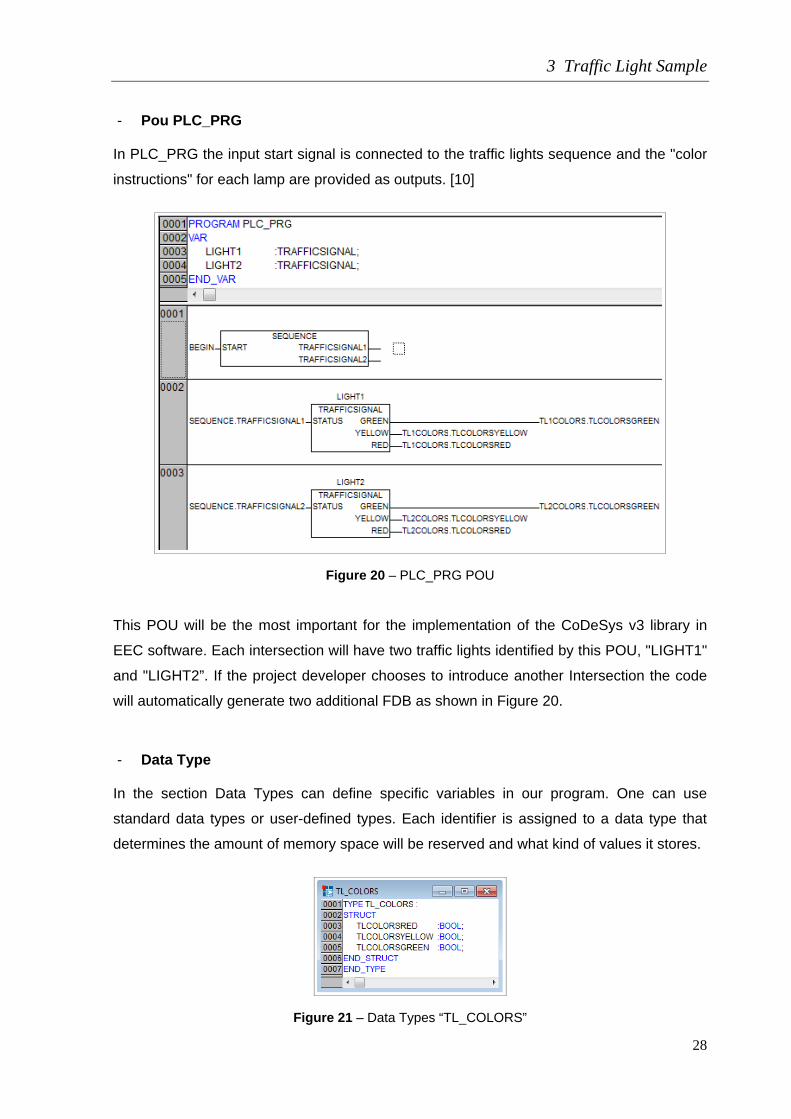
- Pou PLC_PRG In PLC_PRG the input start signal is connected to the traffic lights sequence and the "color
instructions" for each lamp are provided as outputs. [10]
Figure 20 – PLC_PRG POU This POU will be the most important for the implementation of the CoDeSys v3 library in
EEC software. Each intersection will have two traffic lights identified by this POU, "LIGHT1"
and "LIGHT2”. If the project developer chooses to introduce another Intersection the code
will automatically generate two additional FDB as shown in Figure 20.
- Data Type In the section Data Types can define specific variables in our program. One can use
standard data types or user-defined types. Each identifier is assigned to a data type that
determines the amount of memory space will be reserved and what kind of values it stores.
Figure 21 – Data Types “TL_COLORS”

3 Traffic Light Sample
29
- Global Variables Are constants or variables that are common to the whole project can be declared as global
variables, but also network variables that are then used to exchange data with subscribers
of other networks.
Figure 22 – Global Variables - Tasks To also test whether the tasks will be imported correctly, two tasks will be created in the
project as shown in the following two figures.
Figure 23 – Task configuration, Task

3 Traffic Light Sample
30
Parameter Value
Name Test
Priority 31
Type Cyclic
Interval 10ms
Program Call PLC_PRG
Figure 24 – Task configuration, Test_Task
Parameter Value
Name Test_Task
Priority 31
Type Cyclic
Interval 10ms
Program Call PLC_PRG, SEQUENCE
3 Traffic Light Sample
31
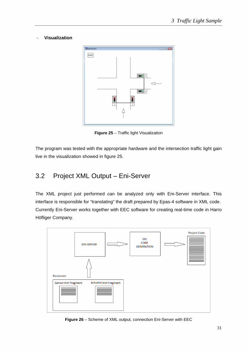
- Visualization
Figure 25 – Traffic light Visualization The program was tested with the appropriate hardware and the intersection traffic light gain
live in the visualization showed in figure 25.
3.2 Project XML Output – Eni-Server
The XML project just performed can be analyzed only with Eni-Server interface. This
interface is responsible for “translating” the draft prepared by Epas-4 software in XML code.
Currently Eni-Server works together with EEC software for creating real-time code in Harro
Höfliger Company.
Figure 26 – Scheme of XML output, connection Eni-Server with EEC

3 Traffic Light Sample
32
Figure 27 – PLC_PRG code visualization with Eni-Server Now with the release of CoDeSys version 3, users can take advantage of PLCopenXML
tool. Unlike Eni-Server this tool is completely open source and eliminates the need to have
a server to translate automation projects in XML format.
In the next picture is possible to visualize a small part of the code of the PLC_PRG POU.
Later in this document it will be done a comparison with the same part but in PLCopenXML
code, CoDeSys version 3.
Figure 28 – PLC_PRG code sample

3 Traffic Light Sample
33
3.3 Import of the Traffic Light Sample into CoDeSys Version
3 and adding of an object oriented function block
To implement the sample project in CoDeSys version 3 was used a new tool available in
this software. This tool is called "Import Epas-4 Project/Library" and easily the draft version
2 is updated to the latest version. Will be analyzed and discussed in this section what kind
of problems a user may find when performing this data transport and whether all mandatory
requirements will be met.
Figure 29 – Import Epas-4 Project/Library The user must fill in all fields such as where is the source file (version 2), the name of the
new project or which Elau controller will be used to execute this project.

3 Traffic Light Sample
34
Figure 30 – Import Epas-4 Project/Library The system identifies the library “STANDARD.LIB” is being used by the project in version 2
and the user is asked if he also wishes that this library is imported. If the library is imported
it is guaranteed that the whole project will work exactly as in version 2.
Figure 31 – Import Epas-4 Project/Library – Allocate libraries

3 Traffic Light Sample
35
Figure 32 – Epas-5 Messages After finishing the imported project there is shown only one error regarding to the modem
device. It is an hardware settings error, the parameters of the new modem driver section do
not coincide with the equipment available in the previous version. This error is not influential
in the successful implementation of the program. After this step is carried out an
build and the project do not have any errors.
Another new feature of the new version is a controller simulation tool. It is now possible run
projects without any connection to any hardware. The project is then simulated by this tool
and it works as it worked in version 2.
The next section will be analyzed the POUs folder. Will be checked if this files have all the
parameters and requisites are in accordance with the project prepared in CoDeSys version
2.
- Program Organizations Units
Figure 33 – POU folder

3 Traffic Light Sample
36
Pou Trafficsignal After the project importation from Epas-4 the POU Trafficsignal from the type “Function
Block” and the language “Function Block Diagram” remains with the same aspect from the
previous version.
Figure 34 – Pou Trafficsignal declaration and body sections Pou Wait This Pou is from type “Function Block” and the language of body section is “Instruction List”.
The program is the same as in Epas-4 but in the current version of Epas-5 (V1.35.15.0) it is
not possible to export the instruction list language with the PLCopenXML tool. This problem
will be mentioned further.

3 Traffic Light Sample
37
Figure 35 – Pou Wait declaration and body sections (Instruction List language)
Figure 36 – Pou Wait declaration and body sections (Structure Text language) To eliminate this error then became necessary to change all “Instruction List” code to
“Structured Text”. It was changed the code of POU wait and all actions of the POU
Sequence.

3 Traffic Light Sample
38
Pou Sequence
Figure 37 – Pou Sequence declaration and body sections

3 Traffic Light Sample
39
Pou PLC_PRG This POU was imported successfully and all requirements were covered.
Figure 38 – Pou PLC_PRG declaration and body sections Data Types
Figure 39 – Data Types Global Variables
Figure 40 – Global variables

3 Traffic Light Sample
40
- Tasks
Figure 41 – Task Configuration parameter Both tasks of the project were imported and both are in agreement with the data entered in
the previous version.
Figure 42 – Task Configuration parameter - Visualization
Figure 43 – Epas-5 Visualization
3 Traffic Light Sample
41
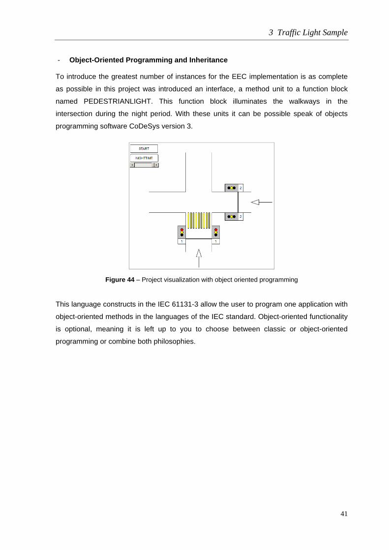
- Object-Oriented Programming and Inheritance To introduce the greatest number of instances for the EEC implementation is as complete
as possible in this project was introduced an interface, a method unit to a function block
named PEDESTRIANLIGHT. This function block illuminates the walkways in the
intersection during the night period. With these units it can be possible speak of objects
programming software CoDeSys version 3.
Figure 44 – Project visualization with object oriented programming This language constructs in the IEC 61131-3 allow the user to program one application with
object-oriented methods in the languages of the IEC standard. Object-oriented functionality
is optional, meaning it is left up to you to choose between classic or object-oriented
programming or combine both philosophies.
3 Traffic Light Sample
42
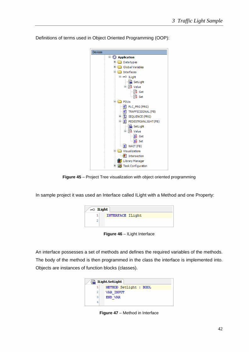
Definitions of terms used in Object Oriented Programming (OOP):
Figure 45 – Project Tree visualization with object oriented programming
In sample project it was used an Interface called ILight with a Method and one Property:
Figure 46 – ILight Interface
An interface possesses a set of methods and defines the required variables of the methods.
The body of the method is then programmed in the class the interface is implemented into.
Objects are instances of function blocks (classes).
Figure 47 – Method in Interface

3 Traffic Light Sample
43
Methods are routines which are firmly assigned to a function block or an interface. They
operate with the data of the function block but can, just like IEC functions; have I/O
variables or local variables.
Figure 48 –Interface property
It’s also used a function block called PEDESTRIANLIGHT. A function block is a class with
exactly one method. With the extension to full class functionality, methods and interfaces
with their methods can be implemented in one function block.
A function block implements an interface with the keyword IMPLEMENTS. Therefore, all
methods of the interface have to be realized in the function block. A function block can
extend a class with the keyword EXTENDS and then inherits the data and the methods of
the class. Which implementation of a method is actually executed when a method is called
via its interface is decided at runtime. This functionality is called polymorphism. [10]
Figure 49 – Function Block with Implements of the Interface

3 Traffic Light Sample
44
Figure 50 – Method aggregate at function block
3.4 XML Comparison of CoDeSys Version 2 and Version 3
This chapter aims to compare two XML tags of the two versions of CoDeSys. This analysis
will serve to assess whether the user can directly export code fragments from one version
to another, and if these will be used by version 3. To better analyze the code it was created
for this investigation a comparison tool called "Xml Dateien Baum Analyse" which is a
program that brings together two xml codes.
Figure 51 – Xml Dateien Baum Analyse, comparison

3 Traffic Light Sample
45
As shown in Figure above, codes of XML projects from both CoDeSys versions are not
identical and there are many differences between them. The existing codes for version 2
may not be used in version 3. It then becomes necessary to perform an export project from
older version to the latest. CoDeSys version 3 has a tool that automatically allows importing
projects and libraries from the previous version. This new feature was analyzed in chapter
3.2.1.
It is also possible to analyse a small part of the codes. These chosen parts must do the
same thing in the project. The first traffic light of Trafficsignal POU is been chosen.
Figure 52 – Traffic Light Function Block Diagram
Figure 53 – CoDeSys version 2 Eni-Server

3 Traffic Light Sample
46
Figure 54 – CoDeSys version 3 PLCopenXML It is possible to observe that the codes are quite different. In Epas-4 through the Eni-Server
it seems an individualized programming across networks while in the PLCopenXML
structure programming is closer to a graphic language where localId have a special
importance.

4 Analysis of Epas-5 XML-Import/Export-Scheme
47
4 Analysis of Epas-5 XML-Import/Export-Scheme
In this chapter is described the analysis of the compliance of traffic light Epas-5
PLCopenXML sample with the PLCopenXML Scheme (according IEC 61131-3).
This analysis is necessary to see if the Epas Scheme is completely in compliance with
PLCopenXML standard. This is a important knowledge because implementation on EEC
will use the Epas-5 XML output and then in EEC only one implementation is necessary to
generate all CoDeSys PLC-systems and also other systems which use the PLCopenXML
scheme.
Figure 55 – Automation project structure check

4 Analysis of Epas-5 XML-Import/Export-Scheme
48
For this analyses it was used a software named “XMLSpy” and another already mention
named “Xml Dateien Baum Analyse”. The first one analyses the compliance with the
standard and the second is only for visual analyses. It was used also “eclipse” software for
generate a blank XML file from the PLCopenXML scheme file and “Notepad++” for reading
all XML files. For CoDeSys environment was used the program Epas-5 version 1.35.15.0.
The next conformance level checks if an automation project is formed at least by a
configuration containing one or more resources in which the source code (program
instances) is going to be downloaded. In order to check if the automation project follows this
architectural style, multiplicity constraints have been added to the PLCopen XML scheme,
as illustrated in the next figure.
The elements of any automation project structure have been highlighted and in particular
the multiplicity of configurations and resources has been modified. [5]
4.1 Export/Import PLCopenXML Tool
Currently, many software programs that are in accordance with IEC 61131-3 standard, as
CoDeSys version 3 or Epas version 5 (which implements CoDeSys version 3), use a tool
that allows export or import an entire project. This tool will allow the exchange of projects
between different kinds of software.
The file created with this tool is in XML format and is standardized by the international
company called PLCopen. In short, A project can be create in IEC 61131-3 compiler, create
an XML file with all the project information’s and it can be open it with another compiler that
possesses this export import tool, then this project will work in a different PLC brand.
Is with this XML file that the CoDeSys version 3 in EEC integration can be done.
An automation project can be create using the existing libraries of EEC and this software
can generate the project in XML code. As this is standard XML we can work with it in any
type of controller that obeys to IEC 61131-3.

4 Analysis of Epas-5 XML-Import/Export-Scheme
49
Figure 56 – Export/Import PLCopenXML tool
4.2 Comparison of Schemes
The XML export/import tool from Epas-5 software will now be tested and compared with the
PLCopen standard scheme. As already mentioned this scheme is consistent with standard
IEC61131-3 and is therefore ensured that all the requirements are met.
The purpose of this analysis is also to understand the PLCopenXML scheme to perform a
compliance implementation in EEC. The XML output of this software must be completely
consistent with this scheme and then it can be opened in any automation application.
Figure 57 – EEC XML generate code

4 Analysis of Epas-5 XML-Import/Export-Scheme
50
1 - Project
This element shows the main tree of the project.
Figure 58 – project diagram
- Header information of an XML file
The file header and content header information originates from the publicly available
specification of the IDA consortium and was specifically developed for usage in a context,
where XML exchange files are generated from different tools of the same or of different
vendors.
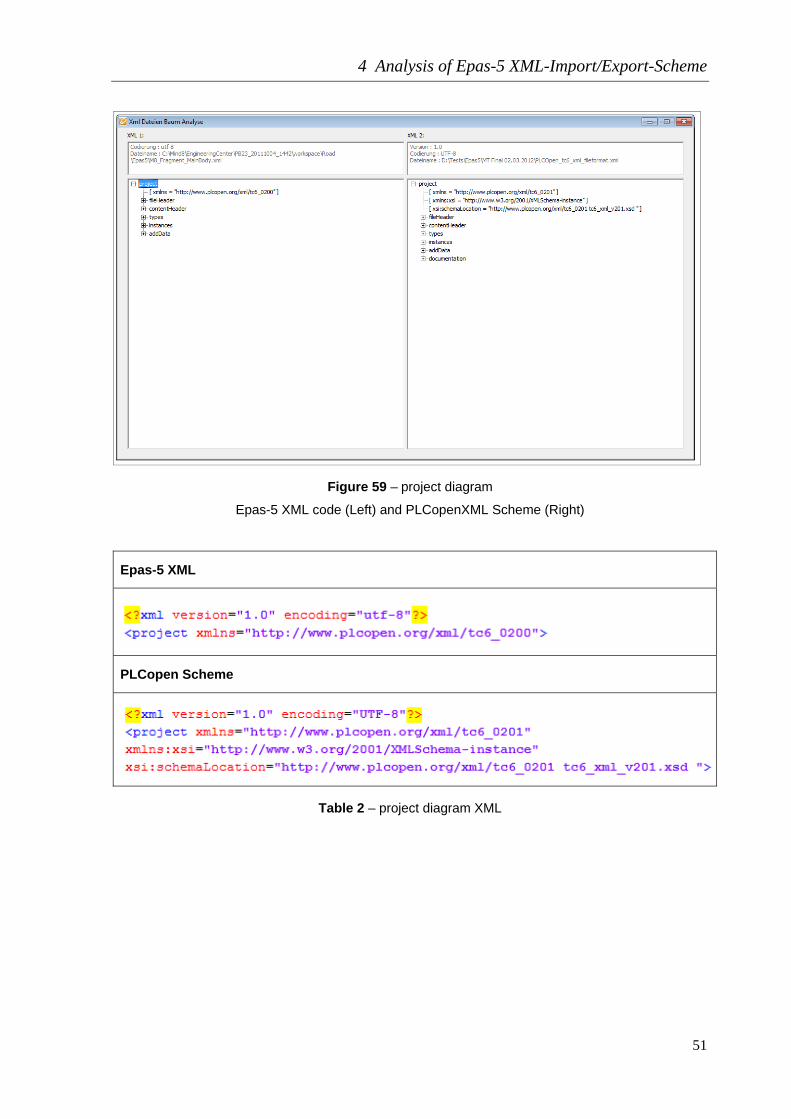
Looking at the differences between standard diagram PLCopen and Epas-5 XML export
tool software it appears that this software does not use the element "documentation". This
element is not a required element and the export tool does not show unconformities with
the PLCopen standard.
One difference is that the export tool is in the PLCopen version 2.0 as showed in parameter
targetNamespace (xmlns) in figure 59. This version is not the latest. The latest version is
PLCopen version 2.01 released in August 2008. [11]
4 Analysis of Epas-5 XML-Import/Export-Scheme
51
Figure 59 – project diagram
Epas-5 XML code (Left) and PLCopenXML Scheme (Right)
Epas-5 XML
PLCopen Scheme
Table 2 – project diagram XML
4 Analysis of Epas-5 XML-Import/Export-Scheme
52
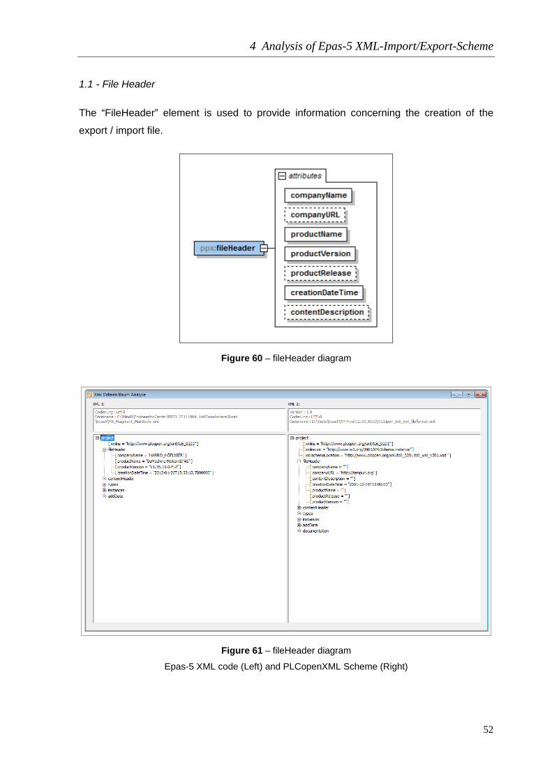
1.1 - File Header
The “FileHeader” element is used to provide information concerning the creation of the
export / import file.
Figure 60 – fileHeader diagram
Figure 61 – fileHeader diagram
Epas-5 XML code (Left) and PLCopenXML Scheme (Right)

4 Analysis of Epas-5 XML-Import/Export-Scheme
53
Epas-5 XML
PLCopen Scheme
Table 3 – fileHeader structure XML
The Epas-5 export tool only has the required attributes “companyName”, “productName”,
“productVersion” and “creationDateTime”. With those attributes the tool is in conformance
with PLCopen standard.
1.2 - Content Header
Figure 62 – contentHeader diagram

4 Analysis of Epas-5 XML-Import/Export-Scheme
54
The “contentHeader” element is used to provide overview information concerning the actual
content of the export / import file. The "name" attribute is required. In case of exporting this
attribute is set to the project name. The other attributes correspond to the equally named
attributes of the "VersionInfo" element as defined in IEC 61499-2. The "comment" element
corresponds to the "Remarks" attribute of the "VersionInfo" element. The attribute
“language” is intended to specify the used language in the definition of the project. The
“comment’ element consists of a string. The element “coordinateInfo” contains the
information for the mapping of the coordinate system. [11]
Figure 63 –contentHeader structure
Epas-5 XML code (Left) and PLCopenXML Scheme (Right)

4 Analysis of Epas-5 XML-Import/Export-Scheme
55
Epas-5 XML
PLCopen Scheme
Table 4 – contentHeader structure XML
In Epas-5 the parameters of contentHeader can be change. The user can choose the menu
“Project” and then “Project Information” section Summary.
Figure 64 –contentHeader project parameters in Epas-5

4 Analysis of Epas-5 XML-Import/Export-Scheme
56
1.2.1 – Coordinate Info
This parameter is responsible for positions and coordinates of inputs, outputs and blocks
positions manly use for graphical information.
Figure 65 – coordinateInfo diagram
Figure 66 – coordinateInfo structure
Epas-5 XML code (Left) and PLCopenXML Scheme (Right)

4 Analysis of Epas-5 XML-Import/Export-Scheme
57
Epas-5 XML
PLCopen Scheme
Table 5 – contentHeader structure XML
Analyzing the figure 66 and the table 5 it is possible conclude that Epas-5 export tool is in
conformance with PLCopen in this parameter although in standard PLCopen has an
optional attribute named “pageSize”.

4 Analysis of Epas-5 XML-Import/Export-Scheme
58
- coordinateInfo / fdb / scaling
In this element is defined the scales x and y for the language Function Diagram Blocks.
Figure 67 – fdb/scaling diagram - coordinateInfo / ld / scaling
In this element is defined the scales x and y for the language Ladder Diagram.
Figure 68 – ld/scaling diagram - coordinateInfo / sfc / scaling
In this element is defined the scales x and y for the language Sequential Function Chart.
Figure 69 – sfc/scaling diagram

4 Analysis of Epas-5 XML-Import/Export-Scheme
59
Figure 70 – fdb, ld, sfc scaling
Epas-5 XML code (Left) and PLCopenXML Scheme (Right) The Epas-5 export tool is in conformance with PLCopen in element coordinateInfo.
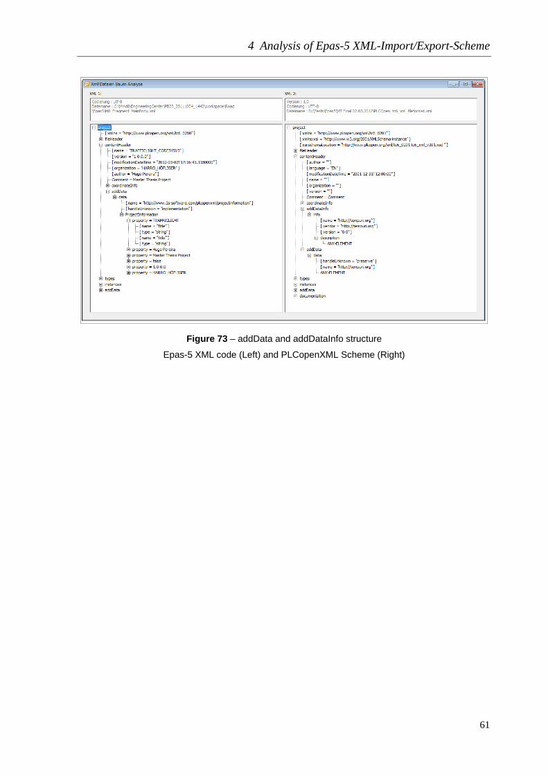
1.2.2 – add Data and add Data Info
For the project and certain objects in the XML file the vendor can include additional data.
Such additional data is vendor-specific. The data itself is given in an addData object.
Additionally in the addDataInfo an URI (uniform resource identifier) is given for the
corresponding addData to uniquely identify the additional data element content. In this
name the vendor domain shall be included to ensure unique names. Using this name the
importing tool may process the addData. The vendor shall specify the behavior of the
importing tool in case the name is not known by the importing tool especially regarding a
later export from this tool. [11]

4 Analysis of Epas-5 XML-Import/Export-Scheme
60
Figure 71 – addData with child data diagram
Figure 72 – addDataInfo with child info diagram
4 Analysis of Epas-5 XML-Import/Export-Scheme
61
Figure 73 – addData and addDataInfo structure
Epas-5 XML code (Left) and PLCopenXML Scheme (Right)

4 Analysis of Epas-5 XML-Import/Export-Scheme
62
Epas-5 XML
PLCopen Scheme
Table 6 – contentHeader/addData addDataInfo structure XML
The Epas-5 export tool is in conformance with PLCopen in element addData.

4 Analysis of Epas-5 XML-Import/Export-Scheme
63
1.3 - Instances
Instances can contain a “configurations” element, which consists of zero or more elements
“configuration”.
Figure 74 – Instances diagram 1.3.1 - Configurations
Configuration represents a group of resources and global variables. It is identified by a
required name. Configuration is for example A PLC system, e.g. a controller in a rack with
multiple (interconnected) CPUs, controlling a cell of machines. In configuration we have:
- Definition of global variables (valid within this configuration);
- Combination of all resources of a PLC system;
- Definition of access paths between configurations;
- Declaration of directly represented (global) variables.
Figure 75 – configurations/configuration diagram

4 Analysis of Epas-5 XML-Import/Export-Scheme
64
Figure 76 – Instances structure
Epas-5 XML code (Left) and PLCopenXML Scheme (Right) The name of the configuration is “LMC_PacDrive” as it´s possible to see in the figure.
Configuration elements are typically declared in textual form. The standard provides a
definition for a graphical representation of a TASK, but the graphical representation of all
other configuration elements is left to the programming system and is therefore
implementation-dependent. [11]
Epas-5 XML
Table 7 – contentHeader/addData addDataInfo structure XML

4 Analysis of Epas-5 XML-Import/Export-Scheme
65
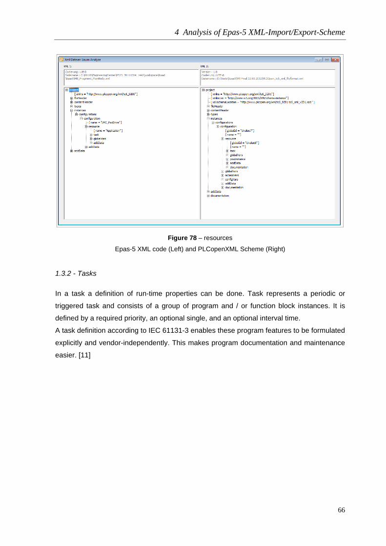
1.3.2 - Resources
Resource represents a group of programs, tasks and global variables. It is identified by a
required name.
A resource is defined in order to assign TASKs to the physical resources of a PLC system.
In a resource we have:
- Definition of global variables (valid within this resource);
- Assignment of tasks and programs to a resource;
- Invocation of run-time programs with input and output parameters;
- Declaration of directly represented (global) variables.
The resource name assigns a symbolic name to a CPU in a PLC. The types and numbers
of the resources in a PLC system (individual CPU designations) are provided by the
programming system and checked to ensure that they are used correctly. Global variables,
which are permissible at resource level, can be used for managing the data that are
restricted to one CPU. [11]
Figure 77 – resource diagram
4 Analysis of Epas-5 XML-Import/Export-Scheme
66
Figure 78 – resources
Epas-5 XML code (Left) and PLCopenXML Scheme (Right) 1.3.2 - Tasks
In a task a definition of run-time properties can be done. Task represents a periodic or
triggered task and consists of a group of program and / or function block instances. It is
defined by a required priority, an optional single, and an optional interval time.
A task definition according to IEC 61131-3 enables these program features to be formulated
explicitly and vendor-independently. This makes program documentation and maintenance
easier. [11]

4 Analysis of Epas-5 XML-Import/Export-Scheme
67
Figure 79 – task diagram
Figure 80 – resource/task
Epas-5 XML code (Left) and PLCopen XML Scheme (Right)

4 Analysis of Epas-5 XML-Import/Export-Scheme
68
Epas-5 XML
PLCopen Scheme
Table 8 – task structure XML
After this analysis it was found that the extracted XML from software Epas-5 is in
compliance with the PLCopen scheme. In this section, only some parameters were
analyzed. A more detailed study than can be seen in the appendix to this document.

5 Creation of the Eplan Engineering Center Model
69
5 Creation of the Eplan Engineering Center Model
For this work to be understood more simply was conceived a project of a Road for
automobile traffic. For this project could be modular on this road the user can introduce one
or more intersections. Each intersection has two traffic lights for each direction of
intersection.
Figure 81 – Eplan Engineering Center Road project
The aim of this project is to demonstrate that it is possible to generate CoDeSys version 3
PLC code. It is possible extrapolate this small example project to a machine with
components as a modular sensor or actuator. In this case was created a main road project
and the user can put as many intersections he want. In addition to the modular component
"Intersection" it is possible to put n modular components, but the goal is to be simple and
perceptible by all.

5 Creation of the Eplan Engineering Center Model
70
5.1 Mechatronic Architecture Library Creation
First it is necessary to split the project and put all the components by levels of functionality
and structure. The levels of structure will be:
- Station (Machine);
- Stationcomponent (Component of the machine);
- Component.
Later, the design of each component will be referred to those elements described.
Figure 82 – T_Mechatronik_Architektur construction
In this library it will be used one pre-defined base-library called Engineering.
Figure 83 – T_Mechatronik_Architektur library

5 Creation of the Eplan Engineering Center Model
71
5.2 Epas-5 Architecture Library Creation
This library is the main responsible for the CoDeSys version 3 code generate
Figure 84 – Epas-5 _Architektur library
TextDiscipline is a pre-defined library. This library is capable from the functional
configuration of a mechatronik system generate an element of text (source code).
Figure 85 – Epas5 _Architektur tree view

5 Creation of the Eplan Engineering Center Model
72
The library “Epas5_Architekture” has two main folders, “Epas5” with the text discipline
library and “levelcomponents” with the components that will be used later in the creation of
the source code fragments.
In Epas5 folder user can define the entire library for example, where is the text source that
will be used to generate the code source for PLC project (resources).
Figure 86 – Epas5 _Architektur path to resources of the project
In “Levelcomponents” The “Body” level object is the hull for the main Epas-5 code, with
other words it will contain the PLCopenXML output from the project constructed in Epas-5
(CoDeSys version 3) for the Road project like we have seen in previous chapter. The
“Fragment” level object is the hull for fragments of little codes that we introduce in the main
code depending of the construction of the project.
Just to remember these two objects are just hulls and they will be used further in this
chapter.

5 Creation of the Eplan Engineering Center Model
73
5.3 Mechatronic Construction Library Creation
The “T_Mechatronik_Construction” library will be the working library of the project Road. In
this library are three main folders:
- CoDeSysV3 – this folder contains the body and the fragments for the generation of
XML code.
- Mechatronik – Is defined the Mechatronik structure.
- Parameters – All the parameters for the project will be save in this folder.
Figure 87 – T_Mechatronik_Construction tree view
Figure 88 – T_Mechatronik_Construction tree view

5 Creation of the Eplan Engineering Center Model
74
CoDeSysV3 Folder:
CoDeSysV3 contains the folder “Bodys” which contain the main body text file of the
ExportPLCopenXML of Epas-5 Road project, called “M8_Fragment_MainBody”.
Figure 89 – M8_Fragment_MainBody Data
In Datei (Data) user can visualize all the XML from the Road original project. The letters in
blue color are parameters we can change in EEC. In fileHeader section we can change
“Company Name” and the parameter is called “M8_CompanyName” and so on. These
features allow the user to personalize each machine for each customer. The main code is
the same for the same kind of machines but they are never equals.

5 Creation of the Eplan Engineering Center Model
75
For the simple introducing of these parameters it is possible to create a user friendly user
interface in EEC software like the next figure.
Figure 90 – Road traffic light configuration project form, File and Content Header Parameters
The PLCopenXML output from EEC is in the next figure and as we can see all parameters
are with the complete information of the previous form.

5 Creation of the Eplan Engineering Center Model
76
Figure 91 – Road traffic light PLCopenXML EEC output
Beyond these parameters in “M8_Fragment_MainBody” user have to introduce another
function called “LOOP”. This function is called to repeat the text fragments many times as
selected by the user or simply to replace the main body in the places where this function is
referred to the text fragments released by the parameters listed on the form. Normally this
function is placed in the Epas-5 code where the original text to be replaced is located. In
this project we have four functions “LOOP”, they are:
5 Creation of the Eplan Engineering Center Model
77
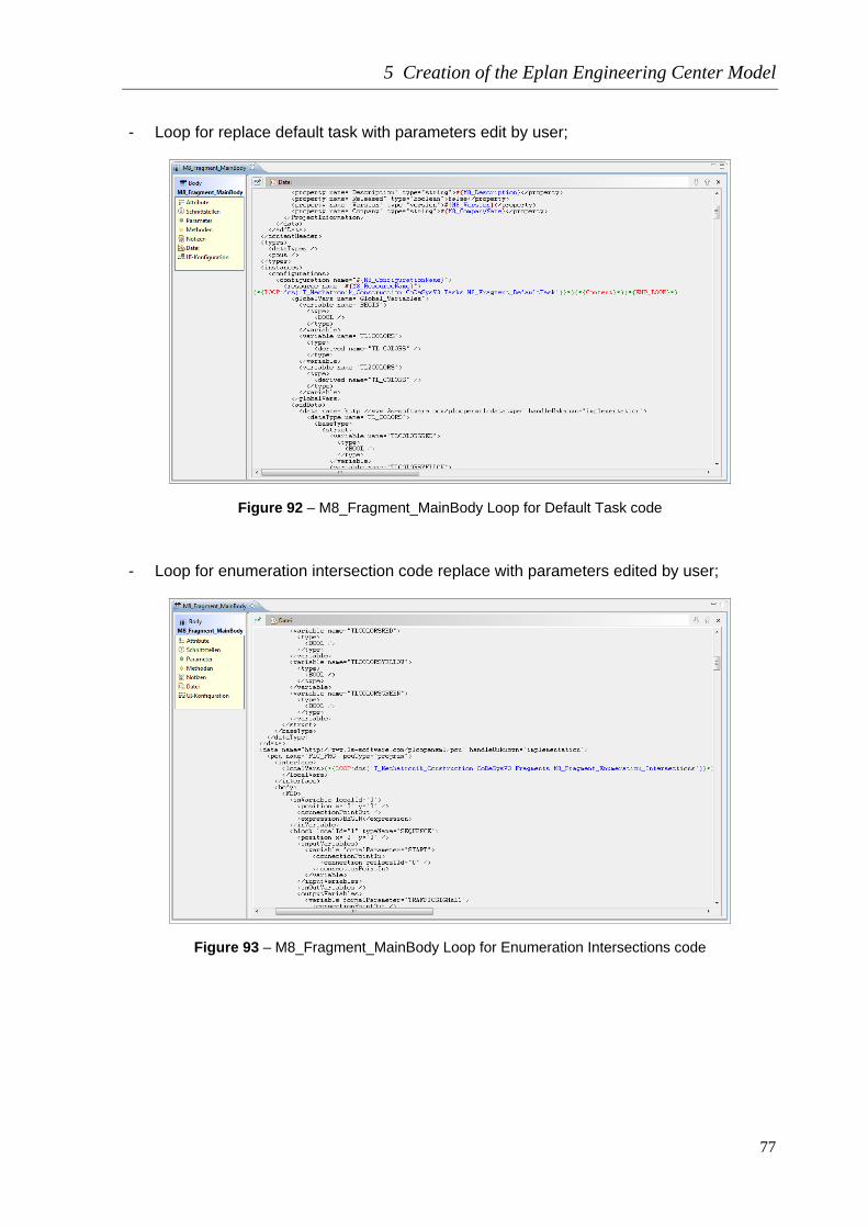
- Loop for replace default task with parameters edit by user;
Figure 92 – M8_Fragment_MainBody Loop for Default Task code
- Loop for enumeration intersection code replace with parameters edited by user;
Figure 93 – M8_Fragment_MainBody Loop for Enumeration Intersections code

5 Creation of the Eplan Engineering Center Model
78
- Loop for body intersection code replace with parameters edited by user;
Figure 94 – M8_Fragment_MainBody Loop for Body Intersections code
- Loop for hardware devices code replace;
Figure 95 – M8_Fragment_MainBody Loop for devices code

5 Creation of the Eplan Engineering Center Model
79
Controller folder:
For example user can create a fragment or several fragments for several PLC devices in
project and then he can introduce or replace in main body of code the fragment belong to
the device we will use. Maybe if you need more inputs or outputs in a specific machine than
the usual, it is possible to replace the code from the source code to a “larger” PLC and for
that he only have to choose which PLC he want to implement in the project. The replace
text file is called “M8_Fragment_Controller_LMCx00C”.
Figure 96 – M8_Fragment_Controller_LMCx00C Data
Fragments folder:
In this folder are introduced all fragments for the modular parts of the machine (Road). In
Road project the only modular part sample is a intersection. For each intersection introduce
in project is considered two kinds of fragments:
- Enumerations intersections;
- Body intersections.
The user can edit the project introducing in this sample more intersections with the form of
the Road traffic light configuration project. If he clicks the “Add Intersections” button the
table at the right will be increased with one more intersection line and in XML output the
POU “PLC_PRG” will have another incremental text code.

5 Creation of the Eplan Engineering Center Model
80
Figure 97 – Road traffic light configuration project form, Road Design
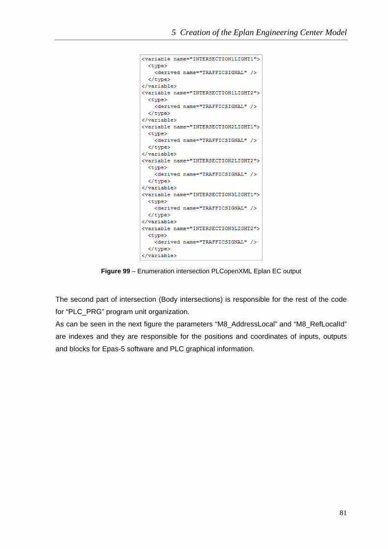
In “M8_Fragment_Enumeration_Intersections” text fragment is enounce the variables of
each intersection. In the next figure is possible to see that each intersection has an
intersection number light1 and light2. Light1 and light2 are the two traffic lights for each
intersection. The parameter “M8_AdressIntersections” will be replaced by the index of each
intersection. In figure 102 is possible to see a sample for three intersections.
Figure 98 – M8_Fragment_Enumeration_Intersections Data
5 Creation of the Eplan Engineering Center Model
81
Figure 99 – Enumeration intersection PLCopenXML Eplan EC output
The second part of intersection (Body intersections) is responsible for the rest of the code
for “PLC_PRG” program unit organization.
As can be seen in the next figure the parameters “M8_AddressLocal” and “M8_RefLocalId”
are indexes and they are responsible for the positions and coordinates of inputs, outputs
and blocks for Epas-5 software and PLC graphical information.

5 Creation of the Eplan Engineering Center Model
82
Figure 100 – M8_Fragment_Body_Intersections data
Figure 101 – Main Body PLCopenXML EEC output

5 Creation of the Eplan Engineering Center Model
83
Tasks folder:
In tasks folder it was introduced the text file “M8_Fragment_DefaultTask”. This text file is
responsible for the default task of the project. This means that it is possible to create or
change some parameters of the tasks inside a project. Editing the task is possible in the
Road form like showed in the next figure. Each project requires at least one task but user
can introduce as many as he want, depending of the complexity of the machine. In this
sample the number of tasks was not modular because this is a sample project and the
modular parameterization is always reach with the intersections. In default task we can
change “Name”, “Kind Of Task”, “Interval” and the “Pou Name” that is the name of the Pou
called when the task is executed.
Figure 102 – Road traffic light configuration project form, Default Task Parameters
Figure 103 – M8_Fragment_DefaultTask data

5 Creation of the Eplan Engineering Center Model
84
Mechatronik Folder:
In this folder is saved the mechatronics parts of the project. Subfolders are the elements of
the “T_Mechatronik_Architektur”, Stations, Stationcomponents and Components.
Figure 104 – T_Mechatronik_Construction Mechatronik tree view
Components folder:
This folder contains the lowest value element “TrafficLight”. This element is from the type
“Component” enounced in the library “T_Mechatronik_Architektur”.
Figure 105 – T_Mechatronik_Construction Traffic Light

5 Creation of the Eplan Engineering Center Model
85
Stationcomponents folder:
This folder contains the medium value element “Intersection”. This element is from the type
“Sationcomponent” enounced in the library “T_Mechatronik_Architektur”. The Intersection
element will be the only modular element of the Road project.
In figure below one “Intersection” has in the “Komponenten” section one “TrafficLight”. This
is the way to define compositions..
Figure 106 – T_Mechatronik_Construction Intersection
In the next figure it is sign now the “M8_Enumeration_of_Intersecions”. This fragment is
responsible for input the variables of one intersection. This fragment has just one parameter
“M8_AddressIntersection” and is responsible to give the index for each intersection. The
formula to calculate this index is programed in Standard column “m8_AddressIntersections
= mc.$M8_Index”. “M8_Index” is an index that represents the number of intersections of a
Road. “mc” means mechatronic components (mechatronic father of this component) and
the all formula means that for one Intersection the project have one
“M8_AddressIntersections”. The project has as many “M8_AddressIntersections”
parameters as Intersections it has.

5 Creation of the Eplan Engineering Center Model
86
Figure 107 – T_Mechatronik_Construction Intersection
The object intersection also has another fragment called “M8_Body_of_Intersection”. In the
next figure it is possible to see the several parameters of this fragment. They are
responsible for all the addresses of the text. These addresses are not constants and that’s
the reason we have to use formulas, depending on the number of intersections the indexes
of these addresses will change according the formulas presents in parameters.
Figure 108 – T_Mechatronik_Construction Intersection

5 Creation of the Eplan Engineering Center Model
87
Station folder:
This folder contains the main project “Road”. This element is from the type “Station”
enounced in the library “T_Mechatronik_Architektur”.
Figure 109 – T_Mechatronik_Construction Road
Inside the project Road we have as components:
- Intersection;
- Add_Intersection;
- M8_Fragment_MainBody;
- M8_Fragment_Controller_LMCx00C;
- M8_Fragment_DefaultTask.
5 Creation of the Eplan Engineering Center Model
88
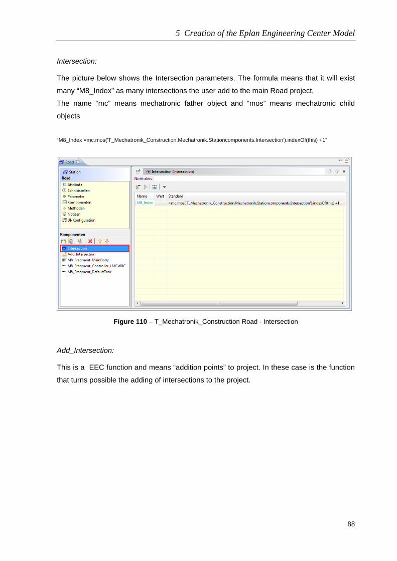
Intersection:
The picture below shows the Intersection parameters. The formula means that it will exist
many “M8_Index” as many intersections the user add to the main Road project.
The name “mc” means mechatronic father object and “mos” means mechatronic child
objects
“M8_Index =mc.mos('T_Mechatronik_Construction.Mechatronik.Stationcomponents.Intersection').indexOf(this) +1”
Figure 110 – T_Mechatronik_Construction Road - Intersection
Add_Intersection:
This is a EEC function and means “addition points” to project. In these case is the function
that turns possible the adding of intersections to the project.

5 Creation of the Eplan Engineering Center Model
89
Figure 111 – T_Mechatronik_Construction Road – Add_Intersection
M8_Fragment_MainBody:
Including this fragment text to the Road project means that when the user generate the
XML code this text will have the most of the line of code. Is inside this code that loops
functions will be introduced for replacing and editing the lines of XML code.
Figure 112 – T_Mechatronik_Construction Road - M8_Fragment_MainBody

5 Creation of the Eplan Engineering Center Model
90
It is possible to see in the parameters section of this fragment all variables that are presents
in this element of text. In the Standard column are the initial values of these parameters.
The user can change all of them.
M8_Fragment_Controller_LMCx00C:
In this parameter the user can change the code for the hardware (PLC) called devices. If
the user has a several numbers of PLC XML Fragments he can choose in an appropriate
form which PLC he will use in the project. In this case the used device was which is the
most common in ELAU projects.
Figure 113 – T_Mechatronik_Construction Road - M8_Fragment_Controller_LMCx00C
5 Creation of the Eplan Engineering Center Model
91
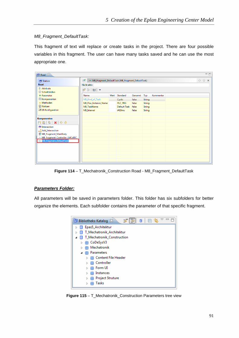
M8_Fragment_DefaultTask:
This fragment of text will replace or create tasks in the project. There are four possible
variables in this fragment. The user can have many tasks saved and he can use the most
appropriate one.
Figure 114 – T_Mechatronik_Construction Road - M8_Fragment_DefaultTask
Parameters Folder:
All parameters will be saved in parameters folder. This folder has six subfolders for better
organize the elements. Each subfolder contains the parameter of that specific fragment.
Figure 115 – T_Mechatronik_Construction Parameters tree view

5 Creation of the Eplan Engineering Center Model
92
Content File Header folder:
This folder contains the parameters of the XML “Content Header” and “File Header”. All of
them are informative parameters.
Figure 116 – Parameters Content File Header tree view
Controller and Form UI folder:
In the figure below the parameters in folder “Controller” and “Form UI” are showed.
“Controller” contains the parameters for the device. “Form UI” contains some parameters
only for organize the form user friendly and those variables don´t have anything to do with
the really project.
Figure 117 – Parameters Controller and Form UI tree view

5 Creation of the Eplan Engineering Center Model
93
Instances folder:
Variables configuration name and resource name can be change also by the user and they
are saved under the subfolder “instances”.
Figure 118 – Parameters Instances tree view
Project Structure folder:
All project structure variables are under this folder. They are specially indexes variables for
coordinates of blocks for function blocks diagrams.
Figure 119 – Parameters Project Structure tree view

5 Creation of the Eplan Engineering Center Model
94
Tasks folder:
The folder “Tasks” contains the four variables that user can change in project tasks.
Figure 120 – Parameters Tasks tree view
5.4 Road Project Construction
Under the Project Katalog window the project will be constructing and in the end is possible
to have a structure like the figure below.
Figure 121 – Project tree view

5 Creation of the Eplan Engineering Center Model
95
The main project is called Road and it has a mechatronik folder with the Road “machine”. A
Road contains in this case three intersections and each intersection one traffic light set. The
user has also the possibility for adding more intersections to the project. Users have also
the folder for the XML code created with text discipline library. It can be seen in the figure
121 “M8_Fragment_MainBody” as the father of all others fragments. In this project there
are three intersections so the project will have three “M8_Enumeration_of_Intersections”
and also three “M8_Body_of_Intersection”. To generate the XML code just choose
“Generate Structure and open file” in Mechatronik and all the code will be processed.
Figure 122 – Generate XML code

5 Creation of the Eplan Engineering Center Model
96
Figure 123 – Generate XML code
After few moments the code appears in the window and it’s ready for testing in PLC. For
appropriate test the output code of EEC the Epas-5 software is open and then one new
project is create and “Import PLCopenXML”. Then, the entire project will be constructing
with all the structure that we have defined in the project design.
Figure 124 – Epas-5 Import PLCopenXML

5 Creation of the Eplan Engineering Center Model
97
Figure 125 – Epas-5 Project Structure
Now it´s possible trying the program with the simulate tool of Epas-5 and everything works
fine like planned.
Figure 126 – Epas-5 Project running

5 Creation of the Eplan Engineering Center Model
98
In this project it was projected a Road with three Intersecions. After open the project in
Epas-5 tool it is possible to check the POU PLC_PRG which contains all the Intersections
of the Road and see if they really exists three Intersections.
Figure 127 – Road PLC_PRG Declaration section
In the declaration part of PLC_PRG POU it is possbible see three Intersection declared.
Each Intersection have two traffic Light. The label of those Epas-5 variables are like the
introduced label in EEC software, on M8_Fragment_Enumeration_Intersections. The code
above is based in PLCopenXML and represents one intersection. This fragment will be
repeat many times, as many Intersections the project will have.
<variable name="INTERSECTION#{M8_AddressIntersections}LIGHT1">
<type>
<derived name="TRAFFICSIGNAL" />
<variable name="INTERSECTION#{M8_AddressIntersections}LIGHT2">
<type>
<derived name="TRAFFICSIGNAL" />

5 Creation of the Eplan Engineering Center Model
99
The next figure represents the body section of the PLC_PRG POU. It can be seen the six
FDB for the three Intersections in the Road project.
Figure 128 – Road PLC_PRG Body section

6 Summary of Results
100
6 Summary of Results
Once completed the CoDeSys version 3 implementation work in EEC software, the
program of this project has been tested several times but there was some errors in the
PLCopenXML export import Epas-5 tool. To achieve and certificate if the XML code is
correctly organized “Sequence” program organization unit was bypassed and manually
imported because the current version of Epas-5 does not support sequential function chart
language.
The program organization unit “Wait” was programmed in structure text language because
instruction list language was not recognized by Epas-5. That’s another “bug” in this latest
update. The mains errors found in Elau Epas-5 Export/Import PLCopen were:
- The XML scheme not update (v2.00);
- Doesn’t support IEC 61131-3 standard instruction list language;
- Doesn’t support IEC 61131-3 standard sequential function chart language;
- When interfaces and implements are introduced in the project, the PLCopenXML
Import does not work.
- Problems with PLCopenXML Import/Export comments;
Although this errors, was guaranteed that the text fragment extracted from the software
EEC works in general and has been proved that the implementation of CoDeSys version 3
in EEC is possible and was well successful.
The main objective of this work was to study all the requirements necessary for the
introduction of the new discipline CoDeSys in EEC software. With these results the
company Harro Höfliger can build a process to create control software to automate their
machines, as it already does with CoDeSys version 2.

6 Summary of Results
101
A small project in both versions of CoDeSys was built. In this project the following items
were analyzed:
- Main software environment differences between the both versions of CoDeSys;
- CoDeSys version 2, Eni-Server XML format;
- CoDeSys version 3 and PLCopen XML format;
- Update Projects with CoDeSys version 3 import tool (version 2 to version 3)
- PLCopenXML Export/Import Projects;
- Analyze errors with Epas5 PLCopenXML Export/Import tool.
With this small project was also possible to develop the “Text Discipline” model to
implement the new version 3 discipline in EEC software. It is possible to conclude that are
many differences between two versions of XML code extracted from Elau-4 and Elau-5.
These codes do not have a structure or a similar semantic which makes it impossible to
reuse the blocks of all existing code in Harro Höfliger Company. Nevertheless all the code
could be analyzed and imported but not directly.
When the projects are update to the latest version they can be exported with PLCopen XML
and then the integration in the future EEC discipline will be possible. The migration of Harro
Höfliger library projects can be made now, but should be considered that Epas-5 software is
still evolving and is not now completely stabilized. This migration should be initiated with
small projects so as to be easily detected some errors that may occur during the import.
After this migration all projects should be tested in PLC's version 3 to ensure everything is
parameterized. New projects may also be inserted in the new discipline of EEC soon as it is
released by Mind8 GmbH & Co. KG.

6 Summary of Results
102
Here some recommendations for the creation of the new library in EEC: Initial conditions
- Software Epas-5 stable;
- CoDeSys V3 Library implement in Eplan Engineering Center;
- New server for store all new version data with a copy of Eni-Server;
Import V2 resources
- With Epas-5 import one simple project with a fragment to new version;
- PLCopenXML for generate XML code;
- Construct the structure in EEC;
- Generate code and test project in PLC for checking eventual errors;
- Organize the disk structure;
- Iniciate the migration of the data folow the steps above;

7 Future Prospects
103
7 Future Prospects
In this document it was demonstrated that IEC 61131-3 standard is very important for nowadays automation. Besides that international standard the PLCopen standard is also crucial for standardizes machines and softwares. Summarizing it will be very good if we all talk the same automation language, and for that we must adopt definitely the two standards above.
It was demonstrated also that the implementation on EEC will be successful and very
helpful for create new processes and methods. I´m very satisfied for can contribute for the
development on such important automation tool.
Eplan Engineering Center is an important tool for working with high quality and fastness.
These kinds of tools use one fast constructing projects and parameterizing without any
“heavy” programming.
CoDeSys version 3 is important and very useful upgrade software. It brings to automation
world some new enhancements that will surely make a big difference in the way you
envision designs and implements automation projects.
Combining all these tools it will be possible to create a great process to develop and design
automated structures. If all procedures are complied with the standards and get the
maximum leverage this tool can actually be a universal tool easy to use with maximum
quality and high standards.

V List of Figures
104
V List of Figures
Figure 1 - Machinery for packaging production for the medical sector ................................................. 8
Figure 2 – Eplan Engineering Center variant management and configuration ..................................... 9
Figure 3 – PLC System Overview ....................................................................................................... 11
Figure 4 – Elau Programmable Logic Controller ................................................................................. 12
Figure 5 – Traffic Light Function Block Diagram ................................................................................. 13
Figure 6 – Physic software model ....................................................................................................... 14
Figure 7 – Program organization unit sample ..................................................................................... 16
Figure 8 – Instruction list code sample ................................................................................................ 17
Figure 9 – Structure text code sample ................................................................................................ 17
Figure 10 – Ladder diagrams samples ................................................................................................ 18
Figure 11 – Functions blocks diagram samples .................................................................................. 18
Figure 12 – Sequential function chart samples ................................................................................... 19
Figure 13 – SFC initial step extended with a (non-Boolean) action block for step Start ..................... 20
Figure 14 – PLCopenXML tool ............................................................................................................ 22
Figure 15 – Eplan Engineering Center generation of documents out of the mechatronic model ....... 23
Figure 16 – POU folder ....................................................................................................................... 25
Figure 17 – Trafficsignal POU ............................................................................................................. 26
Figure 18 – Wait POU ......................................................................................................................... 26
Figure 19 – Sequence POU ................................................................................................................ 27
Figure 20 – PLC_PRG POU ................................................................................................................ 28
Figure 21 – Data Types “TL_COLORS” .............................................................................................. 28
Figure 22 – Global Variables ............................................................................................................... 29
Figure 23 – Task configuration, Task .................................................................................................. 29
Figure 24 – Task configuration, Test_Task ......................................................................................... 30
Figure 25 – Traffic light Visualization .................................................................................................. 31
Figure 26 – Scheme of XML output, connection Eni-Server with EEC ............................................... 31
Figure 27 – PLC_PRG code visualization with Eni-Server ................................................................. 32
Figure 28 – PLC_PRG code sample ................................................................................................... 32
Figure 29 – Import Epas-4 Project/Library .......................................................................................... 33
Figure 30 – Import Epas-4 Project/Library .......................................................................................... 34
Figure 31 – Import Epas-4 Project/Library – Allocate libraries ............................................................ 34
Figure 32 – Epas-5 Messages ............................................................................................................ 35
Figure 33 – POU folder ....................................................................................................................... 35
Figure 34 – Pou Trafficsignal declaration and body sections ............................................................. 36
Figure 35 – Pou Wait declaration and body sections (Instruction List language) ............................... 37
Figure 36 – Pou Wait declaration and body sections (Structure Text language) ................................ 37
Figure 37 – Pou Sequence declaration and body sections ................................................................. 38

V List of Figures
105
Figure 38 – Pou PLC_PRG declaration and body sections ................................................................ 39
Figure 39 – Data Types ....................................................................................................................... 39
Figure 40 – Global variables ............................................................................................................... 39
Figure 41 – Task Configuration parameter ......................................................................................... 40
Figure 42 – Task Configuration parameter ......................................................................................... 40
Figure 43 – Epas-5 Visualization......................................................................................................... 40
Figure 44 – Project visualization with object oriented programming ................................................... 41
Figure 45 – Project Tree visualization with object oriented programming .......................................... 42
Figure 46 – ILight Interface ................................................................................................................. 42
Figure 47 – Method in Interface .......................................................................................................... 42
Figure 48 –Interface property .............................................................................................................. 43
Figure 49 – Function Block with Implements of the Interface ............................................................. 43
Figure 50 – Method aggregate at function block ................................................................................. 44
Figure 51 – Xml Dateien Baum Analyse, comparison ........................................................................ 44
Figure 52 – Traffic Light Function Block Diagram ............................................................................... 45
Figure 53 – CoDeSys version 2 Eni-Server ........................................................................................ 45
Figure 54 – CoDeSys version 3 PLCopenXML ................................................................................... 46
Figure 55 – Automation project structure check .................................................................................. 47
Figure 56 – Export/Import PLCopenXML tool ..................................................................................... 49
Figure 57 – EEC XML generate code ................................................................................................. 49
Figure 58 – project diagram ................................................................................................................ 50
Figure 59 – project diagram ................................................................................................................ 51
Figure 60 – fileHeader diagram ........................................................................................................... 52
Figure 61 – fileHeader diagram ........................................................................................................... 52
Figure 62 – contentHeader diagram ................................................................................................... 53
Figure 63 –contentHeader structure ................................................................................................... 54
Figure 64 –contentHeader project parameters in Epas-5 ................................................................... 55
Figure 65 – coordinateInfo diagram .................................................................................................... 56
Figure 66 – coordinateInfo structure ................................................................................................... 56
Figure 67 – fdb/scaling diagram .......................................................................................................... 58
Figure 68 – ld/scaling diagram ............................................................................................................ 58
Figure 69 – sfc/scaling diagram .......................................................................................................... 58
Figure 70 – fdb, ld, sfc scaling ............................................................................................................. 59
Figure 71 – addData with child data diagram ...................................................................................... 60
Figure 72 – addDataInfo with child info diagram ................................................................................. 60
Figure 73 – addData and addDataInfo structure ................................................................................. 61
Figure 74 – Instances diagram ............................................................................................................ 63
Figure 75 – configurations/configuration diagram ............................................................................... 63
Figure 76 – Instances structure ........................................................................................................... 64
Figure 77 – resource diagram ............................................................................................................. 65

V List of Figures
106
Figure 78 – resources ......................................................................................................................... 66
Figure 79 – task diagram ..................................................................................................................... 67
Figure 80 – resource/task .................................................................................................................... 67
Figure 81 – Eplan Engineering Center Road project .......................................................................... 69
Figure 82 – T_Mechatronik_Architektur construction .......................................................................... 70
Figure 83 – T_Mechatronik_Architektur library ................................................................................... 70
Figure 84 – Epas-5 _Architektur library ............................................................................................... 71
Figure 85 – Epas5 _Architektur tree view ........................................................................................... 71
Figure 86 – Epas5 _Architektur path to resources of the project ........................................................ 72
Figure 87 – T_Mechatronik_Construction tree view ............................................................................ 73
Figure 88 – T_Mechatronik_Construction tree view ............................................................................ 73
Figure 89 – M8_Fragment_MainBody Data ........................................................................................ 74
Figure 90 – Road traffic light configuration project form, File and Content Header Parameters ........ 75
Figure 91 – Road traffic light PLCopenXML EEC output .................................................................... 76
Figure 92 – M8_Fragment_MainBody Loop for Default Task code .................................................... 77
Figure 93 – M8_Fragment_MainBody Loop for Enumeration Intersections code .............................. 77
Figure 94 – M8_Fragment_MainBody Loop for Body Intersections code ........................................... 78
Figure 95 – M8_Fragment_MainBody Loop for devices code ............................................................ 78
Figure 96 – M8_Fragment_Controller_LMCx00C Data ...................................................................... 79
Figure 97 – Road traffic light configuration project form, Road Design .............................................. 80
Figure 98 – M8_Fragment_Enumeration_Intersections Data ............................................................. 80
Figure 99 – Enumeration intersection PLCopenXML Eplan EC output .............................................. 81
Figure 100 – M8_Fragment_Body_Intersections data ........................................................................ 82
Figure 101 – Main Body PLCopenXML EEC output ........................................................................... 82
Figure 102 – Road traffic light configuration project form, Default Task Parameters ......................... 83
Figure 103 – M8_Fragment_DefaultTask data ................................................................................... 83
Figure 104 – T_Mechatronik_Construction Mechatronik tree view ..................................................... 84
Figure 105 – T_Mechatronik_Construction Traffic Light ..................................................................... 84
Figure 106 – T_Mechatronik_Construction Intersection ..................................................................... 85
Figure 107 – T_Mechatronik_Construction Intersection ..................................................................... 86
Figure 108 – T_Mechatronik_Construction Intersection ..................................................................... 86
Figure 109 – T_Mechatronik_Construction Road ............................................................................... 87
Figure 110 – T_Mechatronik_Construction Road - Intersection ......................................................... 88
Figure 111 – T_Mechatronik_Construction Road – Add_Intersection ................................................ 89
Figure 112 – T_Mechatronik_Construction Road - M8_Fragment_MainBody ................................... 89
Figure 113 – T_Mechatronik_Construction Road - M8_Fragment_Controller_LMCx00C .................. 90
Figure 114 – T_Mechatronik_Construction Road - M8_Fragment_DefaultTask ................................ 91
Figure 115 – T_Mechatronik_Construction Parameters tree view ...................................................... 91
Figure 116 – Parameters Content File Header tree view .................................................................... 92
Figure 117 – Parameters Controller and Form UI tree view ............................................................... 92

V List of Figures
107
Figure 118 – Parameters Instances tree view ..................................................................................... 93
Figure 119 – Parameters Project Structure tree view ......................................................................... 93
Figure 120 – Parameters Tasks tree view .......................................................................................... 94
Figure 121 – Project tree view ............................................................................................................. 94
Figure 122 – Generate XML code ....................................................................................................... 95
Figure 123 – Generate XML code ....................................................................................................... 96
Figure 124 – Epas-5 Import PLCopenXML ......................................................................................... 96
Figure 125 – Epas-5 Project Structure ................................................................................................ 97
Figure 126 – Epas-5 Project running .................................................................................................. 97
Figure 127 – Road PLC_PRG Declaration section ............................................................................. 98
Figure 128 – Road PLC_PRG Body section ....................................................................................... 99

VI List of Tables
108
VI List of Tables
Table 1 – EEC CoDeSys version 3 implementation structure ............................................................ 24
Table 2 – project diagram XML ........................................................................................................... 51
Table 3 – fileHeader structure XML..................................................................................................... 53
Table 4 – contentHeader structure XML ............................................................................................. 55
Table 5 – contentHeader structure XML ............................................................................................. 57
Table 6 – contentHeader/addData addDataInfo structure XML .......................................................... 62
Table 7 – contentHeader/addData addDataInfo structure XML .......................................................... 64
Table 8 – task structure XML .............................................................................................................. 68

VII References
109
VII References
[1] International Electrotechnical Commission. IEC International Standard IEC 61131
3:2003, Programmable Controllers, Part 3: Programming Languages, 2003.
[2] XML Formats for IEC 61131-3 version 2.01, PLCopen Technical Committee 6,
Technical Paper.
[3] PLCopen home-page: http://www.plcopen.org.
[4] XML, available at: http://www.w3.org/XML.
[5] E. Estévez, M. Marcos, E. Irisarri “Analysis of IEC 61131-3 Compliance through
PLCopen XML Interface”.
[6] Karl-Heinz John y Michael Tiegelkamp, “IEC 61131-3: Programming Industrial
Automation Systems”, Second edition. Springer. 2001.
[7] Edouard Tisserant, Laurent Bessard, and Mário de Sousa “An Open Source IEC
61131-3 Integrated Development Environment”.
[8] IDC Technologies Industrial Programming using lEC 61131-3 for PLCs.
[9] 3S Software home page: http://www.3s-software.com.
[10] Elau, Epas version 4 and version 5 Help menu.
[11] Technical Paper PLCopen Technical Committee 6 XML Formats for IEC 61131-3
version 2.01 – Official Release.
[12] Wikipedia the free encyclopedia home-page: http://en.wikipedia.org.

VIII Appendix
110
VIII Appendix
- Epas-5 / PLCopen XML a) Analyses of Export PLCopenXML Road Project
- Structure of the CD_Master Thesis of Hugo Pereira 04.2012

VIII Appendix
111
a) Analyses of Export PLCopenXML Road Project
After doing the project, must be analyzed the Export code PLCopenXML from the Road
project. This analysis will be used to refer all objects that make up the XML. Then will serve
for the implementation of the CoDeSys software EEC.
The most important objects in this analysis are:
- POUs;
- Interfaces;
- Actions;
- Methods;
- Properties;
- Transitions;
- Global variables;
- Data types;
- Tasks;
- Devices;
- Applications;
- Project information.
These objects may for example be easily edited, deleted or duplicated in software EEC. For
this reason it is important to know the exact location of them.

VIII Appendix
112
1 – Header Information
Epas-5 XML code (project structure)
Here we have the main project and information about the PLCopenXML version used.
2 – File Header
Epas-5 XML code (fileHeader structure)
Here we have the information’s about the project and the user.
3 – Content Header
Here we have the information’s about the project and the user. In Epas-5 we can change
the parameters of contentHeader. We can choose the menu “Project” and then “Project
Information” section Summary.
contentHeader project parameters in Epas-5

VIII Appendix
113
Epas-5 XML code (contentHeader structure)
3.1 – Coordinate Info
Epas-5 XML code (coordinateInfo)
The element “coordinateInfo” contains the information for the mapping of the coordinate
system
3.2 – Add Data
For the project and certain objects in the XML file the vendor can include additional data.
Epas-5 XML code (addData)

VIII Appendix
114
4 – Types
Epas-5 XML code (dataTypes/ dataType structure)
5 – Instances
5.1 – configurations / configuration / resource
Epas-5 XML code (instances)

VIII Appendix
115
5.1.2 – Tasks
Tasks control the execution of a set of programs and/or function blocks. These can either
be executed periodically or upon the occurrence of a specified trigger, such as the change
of a variable:
In next figure we have the tasks tree view of EPAS-5 Intersection project. This project has
two tasks, “Task” and “Test_Task”. The first one is the main task of project and “Test_Task”
is only for testing the XML output.
Epas-5 Tree view project
Epas-5 “Task” configuration form

VIII Appendix
116
Epas-5 XML code (Task XML output)
Inside a task can be defined:
- POUs for execute;
- Priority;
- Type of Task, Interval and Interval unit;
- Enable/disable Watchdog, Time and Sensitivity;

VIII Appendix
117
If user look closely the form of the task and its xml code we can conclude that we can fully
configure a task just by changing the xml code. Thus with the implementation in software
EEC can create and edit tasks in a project.
Epas-5 “Test_Task” configuration form
Epas-5 XML code (Test_Task XML output)

VIII Appendix
118
5.1.3 – Global Variables
Epas-5 Tree view project (Global variables)
Epas-5 Global variables declaration
In these variables we have three derived variables data type and one generic data type
variable.
Epas-5 XML code (Global variables XML output)

VIII Appendix
119
Like the Task configuration we can fully configure global variables just by just changing the
xml code. Thus with the implementation in software Mind8 can create and edit global
variables in a project.
5.1.4 – Add Data
5.1.4.1 – Data Types
Epas-5 Tree view project (Data types)
Epas-5 Data types “TL_COLORS” declaration
Epas-5 XML code (Data type “TL_TIMEOFDAY” XML output)

VIII Appendix
120
Epas-5 Data types “TL_TIMEOFDAY” declaration
Epas-5 XML code (Data type “TL_COLORS” XML output)
Again we can fully configure Data Types just by just changing the xml code. Thus with the
implementation in software Mind8 can create and edit Data Types in a project.

VIII Appendix
121
5.1.4.2 – Interface
Interfaces can be used to organize methods which are used by function blocks. An
"Interface" is a POU describing a collection of method-prototypes. "Prototype" means that
just declarations but no implementation is contained. A function block can implement one or
several interfaces which mean that basically all methods of the interface(s) are available in
the function block.
The advantage: The method calls are defined and thus unique for all function blocks
implementing the same interface. Within a function block the methods have to be filled with
implementation code.
Epas-5 Tree view project (Interfaces)
Epas-5 Interface “ILight” declaration

VIII Appendix
122
Epas-5 XML code (Interface “ILight” XML output)
Epas-5 Method “SetLight” declaration
Epas-5 XML code (Method “SetLight” XML output)

VIII Appendix
123
Epas-5 Property “Value” declaration
Epas-5 XML code (Properties “Value” XML output)
5.1.4.3 – Pou / PLC_PRG
Interface / Local variables:
Here is defined all variables of the PLC_PRG program organization unit declaration.
Epas-5 Tree view project (POUs)

VIII Appendix
124
Epas-5 POU “PLC_PRG” declaration
Epas-5 XML code (POU “PLC_PRG” variables XML output)

VIII Appendix
125
Body / FDB:
In this section it will be analyze the POUs body XML. This part of XML is mainly with
coordinate factors.
Epas-5 POU “PLC_PRG” Body
- PedestrianLight
Epas-5 PEDESTRIANLIGHT block
SVG is a vector graphics format that follows the XML grammar. It defines three types of
graphical objects: vector graphical objects, such as lines, ellipses, rectangle, etc. that can
be grouped, formatted, transformed and composed.
Related to the IEC 61131-3 graphical languages and, in particular, to the FBD language, a
limited set of SVG elements are needed, as illustrated in Fig. 4 along with its expression in
SVG language.
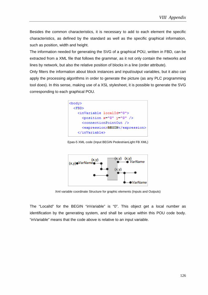
VIII Appendix
126
Besides the common characteristics, it is necessary to add to each element the specific
characteristics, as defined by the standard as well as the specific graphical information,
such as position, width and height.
The information needed for generating the SVG of a graphical POU, written in FBD, can be
extracted from a XML file that follows the grammar, as it not only contain the networks and
lines by network, but also the relative position of blocks in a line (order attribute).
Only filters the information about block instances and input/output variables, but it also can
apply the processing algorithms in order to generate the picture (as any PLC programming
tool does). In this sense, making use of a XSL stylesheet, it is possible to generate the SVG
corresponding to each graphical POU.
Epas-5 XML code (Input BEGIN PedestrianLight FB XML)
Xml variable coordinate Structure for graphic elements (Inputs and Outputs)
The “LocalId” for the BEGIN “inVariable” is “0”. This object get a local number as
identification by the generating system, and shall be unique within this POU code body.
“inVariable” means that the code above is relative to an input variable.
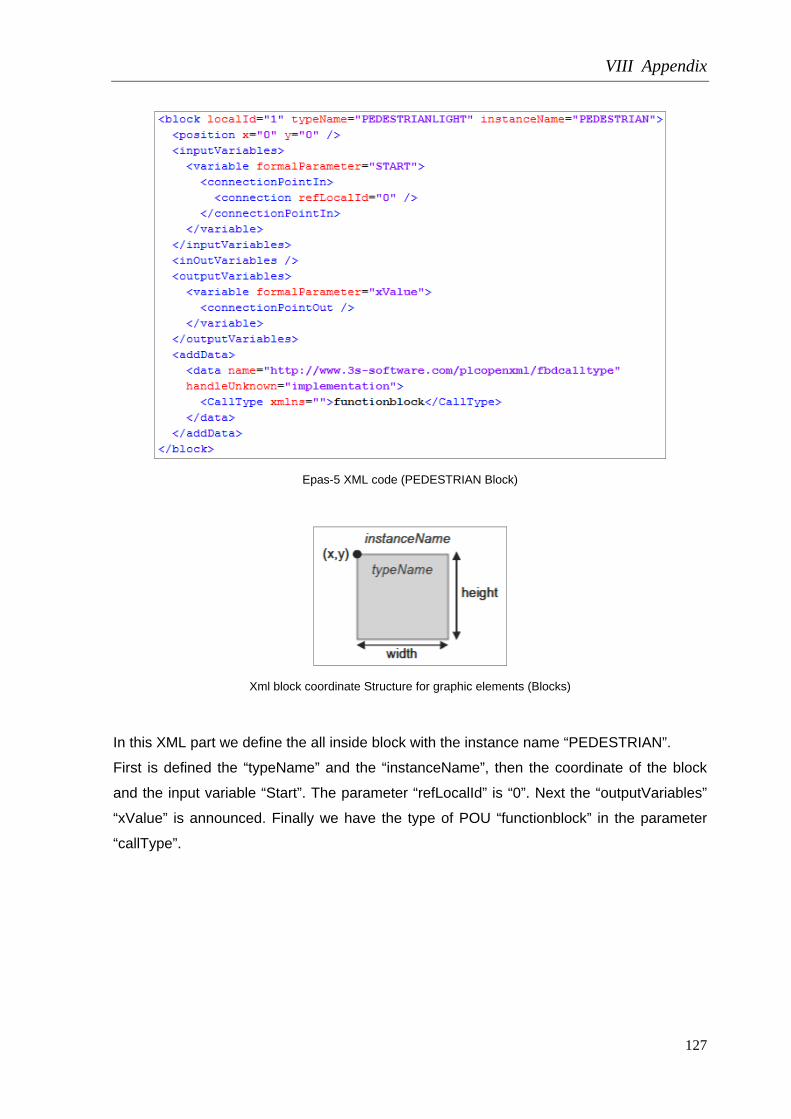
VIII Appendix
127
Epas-5 XML code (PEDESTRIAN Block)
Xml block coordinate Structure for graphic elements (Blocks)
In this XML part we define the all inside block with the instance name “PEDESTRIAN”.
First is defined the “typeName” and the “instanceName”, then the coordinate of the block
and the input variable “Start”. The parameter “refLocalId” is “0”. Next the “outputVariables”
“xValue” is announced. Finally we have the type of POU “functionblock” in the parameter
“callType”.

VIII Appendix
128
- Sequence
Epas-5 SEQUENCE block
Epas-5 XML code (Input BEGIN SEQUENCE FB XML)
The “localId” of this object has the number “2”, because the number “0” is already been
used by a “inVariable” and the number “1” by the previous block.
Epas-5 XML code (SEQUENCE Block)

VIII Appendix
129
The parameter “refLocalId” increase one unit when we change of block. In the parameter
“callType” we have the type of POU “program”.
- Trafficsignal Light1
TRAFFICSIGNAL LIGHT1 block
Epas-5 XML code (Input SEQUENCE.TRAFFICSIGNAL1 XML)
Epas-5 XML code (TRAFFICSIGNAL LIGHT1 Block)

VIII Appendix
130
Epas-5 XML code (output TL1COLORS.TLCOLORSGREEN XML)
- Trafficsignal Light2
TRAFFICSIGNAL LIGHT2 block
Epas-5 XML code (Input SEQUENCE.TRAFFICSIGNAL2 XML)

VIII Appendix
131
Epas-5 XML code (TRAFFICSIGNAL LIGHT2 Block)
Epas-5 XML code (output TL2COLORS.TLCOLORSGREEN XML)
With the closing of “FDB and “body” we finish the graphical information for this POU.

VIII Appendix
132
5.1.4.4 – Pou / TRAFFICSIGNAL
Interface / Local variables:
Here is defined all variables of the TRAFFICSIGNAL program organization unit declaration.
Epas-5 POU “TRAFFICSIGNAL” declaration
Epas-5 XML code (POU TRAFFICSIGNAL variables XML output)

VIII Appendix
133
Body / FDB:
In this section it will be analyze the POUs body XML.
Epas-5 POU “TRAFFICSIGNAL” Body
- Network1:
Epas-5 POU “TRAFFICSIGNAL” Block 1

VIII Appendix
134
Epas-5 XML code (Inputs STATUS and “1” XML)
Epas-5 XML code (TRAFFICSIGNAL Block 1)
Epas-5 XML code (output GREEN XML)

VIII Appendix
135
- Network2:
Epas-5 POU “TRAFFICSIGNAL” Network 2
Epas-5 XML code (Inputs STATUS and “2”)

VIII Appendix
136
Epas-5 XML code (TRAFFICSIGNAL Network 2 Block “EQ”)
Epas-5 XML code (Inputs STATUS and “4”)

VIII Appendix
137
Epas-5 XML code (TRAFFICSIGNAL Network 2 Block “EQ”)

VIII Appendix
138
Epas-5 XML code (TRAFFICSIGNAL Network 2 Block “OR”)
Epas-5 XML code (output YELLOW XML)
- Network3:
Epas-5 POU “TRAFFICSIGNAL” Network 3

VIII Appendix
139
Epas-5 XML code (Inputs STATUS and “3”)
Epas-5 XML code (TRAFFICSIGNAL Network 3 Block “EQ”)

VIII Appendix
140
Epas-5 XML code (Inputs STATUS and “4”)
Epas-5 XML code (TRAFFICSIGNAL Network 3 Block “EQ”)

VIII Appendix
141
Epas-5 XML code (TRAFFICSIGNAL Network 3 Block “OR”)
Epas-5 XML code (output RED XML)

VIII Appendix
142
- Network4:
Epas-5 POU “TRAFFICSIGNAL” Network 4
Epas-5 XML code (Inputs STATUS and “5”)
Epas-5 XML code (TRAFFICSIGNAL Network 4)

VIII Appendix
143
Epas-5 XML code (output OFF)
5.1.4.4 – Pou / PEDESTRIANLIGHT
Interface / Local variables:
Here is defined all variables of the PEDESTRIANLIGHT program organization unit
declaration.
Epas-5 Tree view project (PEDESTRIAN POU)
Epas-5 POU “PEDESTRIANLIGHT” declaration

VIII Appendix
144
Epas-5 XML code (POU PEDESTRIANLIGHT variables XML output and Inheritance)
Body / ST:
In this section it will be analyze the POUs body XML.
Epas-5 POU “PEDESTRIANLIGHT” Body

VIII Appendix
145
Epas-5 XML code (PEDESTRIANLIGHT Body)
Add Data / Data:
- Method Interface:
Epas-5 POU Method “SetLight” declaration
Epas-5 XML code (Method SetLight declaration)

VIII Appendix
146
- Method Body / ST:
Epas-5 POU Method “SetLight” body
Epas-5 XML code (Method SetLight body)
- Property Value:
Epas-5 POU Property “Value”
Epas-5 XML code (Property Value)

VIII Appendix
147
- Property Value GetAccessor:
Epas-5 Method Property “Value” GetAcessor
Epas-5 XML code (Property Value GetAccessor)
Epas-5 Method Property “Value” SetAcessor

VIII Appendix
148
Epas-5 XML code (Property Value SetAccessor)
5.1.4.5 – Pou / WAIT
Interface:
Here is defined all variables of the WAIT program organization unit declaration.
Epas-5 POU “WAIT” declaration

VIII Appendix
149
Epas-5 XML code (POU WAIT variables XML)
Body / ST:
Epas-5 POU WAIT body

VIII Appendix
150
Epas-5 XML code (POU WAIT body)
5.1.4.5 – Pou / SEQUENCE
Interface:
Epas-5 Tree view project (SEQUENCE POU)

VIII Appendix
151
Epas-5 POU SEQUENCE declaration
Epas-5 XML code POU SEQUENCE declaration

VIII Appendix
152
Body / SFC:
Epas-5 POU SEQUENCE body section in SFC language

VIII Appendix
153
Epas-5 XML code Init Step
Epas-5 XML code Switch1 Step

VIII Appendix
154
Epas-5 XML code Count Step
Epas-5 XML code Off Step

VIII Appendix
155
Epas-5 XML code Green2 Step
Epas-5 XML code Switch2 Step

VIII Appendix
156
Epas-5 XML code Green1 Step
Actions:
Epas-5 Action Switch1
Epas-5 XML code Action Switch1

VIII Appendix
157
Epas-5 Action Init
Epas-5 XML code Action Init
Epas-5 Action Off
Epas-5 XML code Action Off

VIII Appendix
158
Epas-5 Action Switch2
Epas-5 XML code Action Switch2
Epas-5 Action Count
Epas-5 XML code Action Count

VIII Appendix
159
Epas-5 Action Green2
Epas-5 XML code Action Green2
Epas-5 Action Green1
Epas-5 XML code Action Green1

VIII Appendix
160
Transitions:
Epas-5 Transition EXIT_1
Epas-5 XML code Transition EXIT_1

VIII Appendix
161
Libraries:
Epas-5 XML code Libraries used in Project
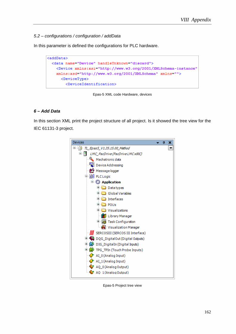
VIII Appendix
162
5.2 – configurations / configuration / addData
In this parameter is defined the configurations for PLC hardware.
Epas-5 XML code Hardware, devices
6 – Add Data
In this section XML print the project structure of all project. Is it showed the tree view for the
IEC 61131-3 project.
Epas-5 Project tree view

VIII Appendix
163
Application and Data Types folder:
Epas-5 Project tree view Application and Data types
POUs folder:
Epas-5 Project tree view POUs folder
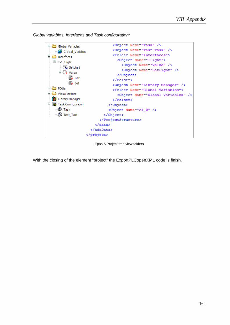
VIII Appendix
164
Global variables, Interfaces and Task configuration:
Epas-5 Project tree view folders
With the closing of the element “project” the ExportPLCopenXML code is finish.