Embed Size (px)
Citation preview
STUDY ON STRUCTURAL ANALYSIS
AND DESIGN OF RCC BIN M.Kishore
1 M.Sanjeev Pandi
1 P.A.Edwin fernando
2
U.G. Student, Department of Civil Engineering, Assistant Professor, Department of Civil Engineering
Akshaya College of Engineering &Technology, Akshaya College of Engineering & Technology,
kinathukadavu. kinathukadavu.
[email protected] [email protected]
Abstract- Storage is one of the essential and vital stages
between the marketing and consumption phases.
Reinforced cement concrete (RCC) is an ideal structural
material for building of permanent bulk storage
facilities. RCC Bin can be flat bottom type or hopper
bottom type. Though flat bottom bins can be built more
easily than hopper bottom bins but it is desirable that
bottom is self cleaning. It is due to this reason that
hopper bottom bins are preferred. Specified the various
parameters such as height of bin, diameter of bin,
properties of the material to be stored ( angle of repose
and density), grade of steel, grade of concrete, the
number of supports, and the components are designed.
For every single case, support numbers have been
varied in multiple of 2, starting from 4say4, 6, 8, 10,
12etc. Conforming to the usual practice, the supports
are assumed to be equally spaced alongside the
periphery. For the designed components (ring girder
dimensions, column cross-section, thickness of wall ),
depending upon height &diameter of the bins, mass
matrix and influence coefficient matrix is then
generated. The, parameters such as fundamental
natural frequency and other frequencies in first 3
modes for bin full and bin empty conditions have
been computed and the normalized Eigen values
have been computed corresponding to first 3 modes.
Further, dynamic & static analysis of bins has been
carried out by taking elements at 2m interval both in
bin (full & empty) conditions. Then the values of
natural frequencies and elemental matrices along
with normalized mode shape values are used in
carrying out dynamic analysis.
I.INTRODUCTION
1.1 General
Food grains form an important part of the
vegetarian Indian diet. The grain production has been
steadily increasing because of advancement in
production technology, but the inappropriate storage
results in high losses in grains. According to World
Bank Report (1999), post-harvest losses in India
amount to 12 to 16 million metric tons of food grains
per annum, an amount that the World Bank stipulates
could nourish one-third of India's poor. The financial
value of these losses amounts to more than Rs 50,000
crores per year (Singh, 2010). Natural contamination
of food grains is greatly influenced by environmental
factors such as type of storage structure, temperature,
pH, moisture, etc (Sashidhar et al, 1992). Length and
purpose of storage, types of structure used, grain
treatment (eg parboiling) and pre-storage practices
are all main variables affecting storage losses. The
value of these regional and crop variations
immediately determines certain necessary
characteristics of crop storage research (Greeley,
1978).During storage, quantitative as well as
qualitative losses occur because of rodents, micro-
organisms, and insects. A huge number of insect
pests have been reported to be associated with stored
grains. The occurrence & numbers of stored grain
insect pests are directly related to climatic and
geographical conditions (Srivastava, and Lal 1985).
Virtually all species have remarkably high rates of
multiplication and within one season may destroy 10-
15% of the grain and contaminate the rest with
undesirable flavors and odors. Insect pests as well
play a essential role in transportation of storage fungi
(1990, Sinha and Sinha).The major construction
materials for storage structures in rural areas are
stones, plant materials ,mud, and bamboo. They are
neither rodent-proof, nor secure from insect and
fungal attack. On average, out of a total 6% loss of
food grain in such storage structures, with reference
to half is due to insects and fungi, and half to rodents.
Various research and development organizations in
India have identified some proven, age-old structures
from certain areas of the country and based on these,
some improvised storage structures have also been
developed and recommended for use at farmer level.
1.2 Definition
RCC BIN is a bulk storage structure. It is
used to store large quantities of materials like grains,
coals etc.
1.3 Applications of Bin
BIN can be used in the industry to store
coals.
It is used to store food grains.
International Journal of Scientific & Engineering Research Volume 9, Issue 3, March-2018 ISSN 2229-5518
60
IJSER © 2018 http://www.ijser.org
IJSER
1.4 Objective of Investigation
The purpose of this project is to
introduce Grain Storage Bins in India to avoid grain
wastage. Grain storage facilities take many forms
depending on the quantity of grain to be stored, the
location of the store and the purpose of storage. In
general grain for food purposes to be stored in
containers provides some protection against insects
and helps prevent quality deterioration. The
requirements for a good storage system include
Prevention of moisture re-entering the grain after
drying, Protection from rodents, birds and insects.
Easiness of loading and unloading, Effective use of
space and ease of maintenance & management.
The project aims to develop strategies that
improve food security of poor households through
increased availability and improved quality of cereals
and pulse foods and better access to markets.
Particularly, it seeks to check the institutional
arrangements associated with community-managed
storage and distribution systems, in addition to solve
the technical requirements dictated by these systems
for the storage of dry-land crops, and to draw wider
lessons concerning decentralized, village-based
approaches to the provision of food security.
The project is focused on providing technical
support to village-level food security project. The
project seeks to enhance the food security of
vulnerable men and their households through group-
based activities that enable women to access
productive resources through the cultivation of
unplanted lands. This group creation will then be
used as an institutional basis for storage, supply and
sale of commodities, in addition to other activities
that can contribute to livelihoods of these households.
A menu of suitable storage arrangements are to be
selected and tested, that give effective safety against
serious grain deterioration.
The building should be elevated and away
from the moist places in the house;
So far as possible, the structure should be
airtight, still at loading and unloading ports.
Rodent-proof materials should be intended
for construction of rural storages;
The area surrounding the building should be
clean to reduce the insect breeding;
The building should be plastered with an
impervious clay layer to keep away from
termite attack, or attack by other insects.
II LITERATURE REVIEW
A.H.Askari and A.E. Elwi (1988). ”Numerical
Prediction of Hopper Bin Pressures” In this paper a simple iterative technique is
developed to model bulk material behaviour when
stored in bin-hopper arrangements. The technique is
tested and found valid in the sense that it captures the
overall behaviour as well as critical design pressures.
The numerical study of wall pressures generated by
bulk materials stored in hopper-bin combinations is
presented. Emphasis is positioned on incipient flow
type pressures on inclined hopper walls. The method
used incorporates a Drucker-Prager-type elastic,
entirely plastic model for an assumed granular bulk
material and Coulomb-type friction for the boundary
interface. A double-layered iterative scheme with a
relaxation function is used to model proper contact
friction interfaces with material nonlinearities.
Throughout the numerical investigation they predict
the hopper bin pressures.
J.G. Teng, J.M. Rotter, “Buckling of rings in column-
supported bins and tanks”
The numerical results from the closed form
solution were compared with finite element shell
analysis ,through the analysis stress non-uniformity
on the buckling predictions is demonstrated
Theories for the out-of-plane buckling of
rings under the same circumferential compression are
well recognized. Still these theories are not
applicable to rings in column-supported bins where
the circumferential stress in the ring varies
considerably over the cross-section and around the
circumference.
This one deals with the out-of-plane
buckling of annular plate rings in column-supported
bins and tanks. The stress distributions in such rings
are first examined by a finite element shell analysis.
A closed-form result for the buckling of rings under
non-uniform circumferential stresses is then derived.
Numerical results from the closed-form solution are
compare with those from a finite element shell
buckling analysis, and close agreement is found.
Then the important effect of stress non-uniformity on
the buckling predictions is established. Finally,
simplified equations are given which are appropriate
for structural design purposes, and which closely
model the predictions of the more exact solution.
Mark E. Killion (1985). ”Design Pressures in
Circular Bins” This article has provided some within reach
into the design pressures in circular bins. It was
revealed that shallow bins (H < 1.5D) can be
designed by static pressures obtained from the
International Journal of Scientific & Engineering Research Volume 9, Issue 3, March-2018 ISSN 2229-5518
61
IJSER © 2018 http://www.ijser.org
IJSER

Coulomb equations. For shallow bins, the properties
of the stored material be able to estimated from
design charts.
Design pressures in the circular bins, which
have been of concern in latest years are examined.
Shallow bin pressures are differentiate from deep bin
pressures. Furthermore, deep bin pressures are
examined for mass flow and funnel flow conditions.
Pressures because of outside temperature variations
are examined.
III Auto CAD Drawing
IV DESIGN CONSIDERATIONS
3.1 Type Of Flow (Funnel Flow):
Funnel flow involves the formation of a flow
channel aligned with the bin outlet, surrounded by a
region in which the material initially stands still.
During bin discharge, if the material is not very
cohesive, the highest part next to the walls
progressively crumbles, feeding the centre channel. If
the material is very cohesive, the bin may stop
emptying owing to the formation of an empty centre
channel surrounded by nonmoving material. In
discharge from a bin with funnel flow, the material
does not all move together, which makes the material
flow at the outlet and the bulk density of the resulting
particulate bed change. Funnel flow. Progressively in
the course of the operation, even when the bin has
almost completely emptied, material is still left
inside, which has not yet moved. This solid,
accumulated in the bin's dead spaces, not only lowers
bin effective capacity but can even become
unserviceable if its properties change with time (by
drying, oxidizing, etc.). Furthermore, this type of
flow makes the negative effects caused by any in
homogeneity of the stored powder, owing to possible
size segregation during filling, more pronounced.
Grain flow through funnel
3.2 Bin Consideration
This involves determining the maximum
angle that the bin walls form with the vertical in the
discharge zone, 8, and the smallest outlet size, D, at
which bin discharge occurs by uninterrupted mass
flow (Figure).
Preliminary considerations, Outlet
obstructions, Bin outlet size must be sufficiently
large to keep from becoming obstructed during
discharge. This phenomenon can stem from doming
if the powder is cohesive, or from blocking up as a
result of structures forming if the particles are
sufficiently large.
Design Variables
3.3 Load Considerations
3.3.1 Bin Loads
Bin Load. - Three types of loads are caused by the
material stored in a bin as shown in below.
a) Horizontal pressure or horizontal load (Pia) acting
on the sidewalls of the bin,
b) Vertical pressure or vertical load ( Pv) acting on
the area of the bin during filling,
c) Frictional wall pressure or frictional wall load
(Pw) introduced into the side walls through wall
friction.
International Journal of Scientific & Engineering Research Volume 9, Issue 3, March-2018 ISSN 2229-5518
62
IJSER © 2018 http://www.ijser.org
IJSER
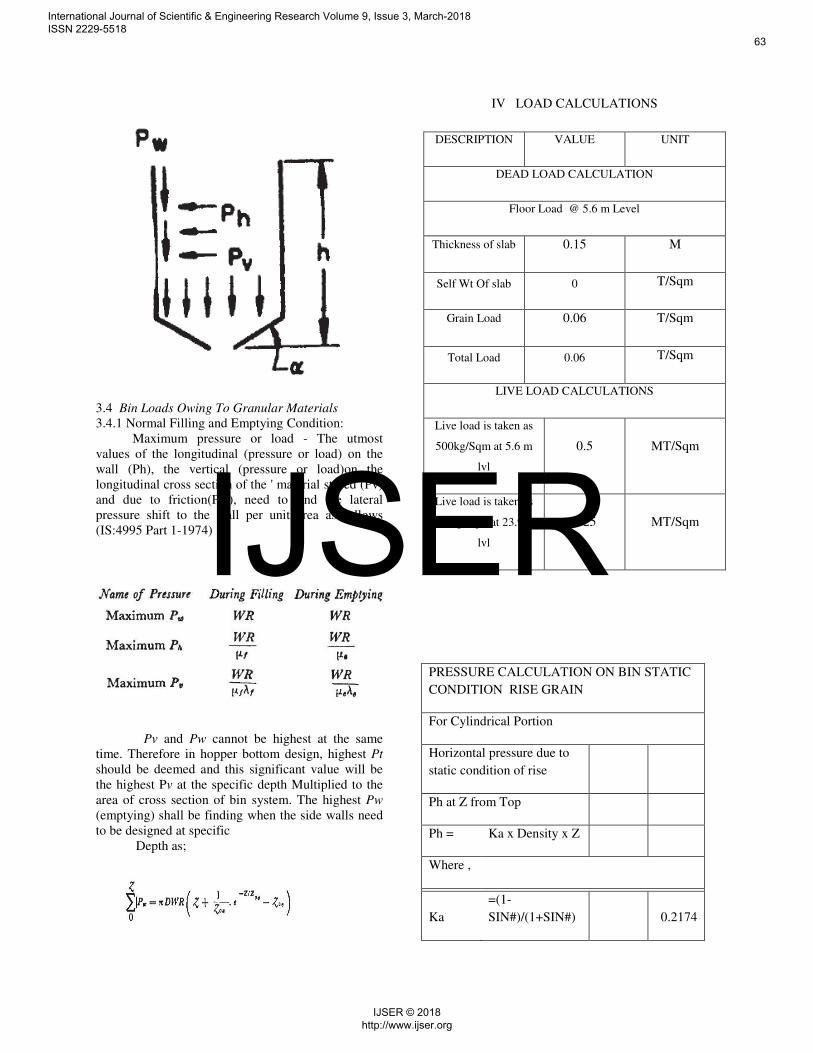
3.4 Bin Loads Owing To Granular Materials
3.4.1 Normal Filling and Emptying Condition:
Maximum pressure or load - The utmost
values of the longitudinal (pressure or load) on the
wall (Ph), the vertical (pressure or load)on the
longitudinal cross section of the ' material stored (Pv)
and due to friction(Pw), need to find the lateral
pressure shift to the wall per unit area as follows
(IS:4995 Part 1-1974)
Pv and Pw cannot be highest at the same
time. Therefore in hopper bottom design, highest Pt
should be deemed and this significant value will be
the highest Pv at the specific depth Multiplied to the
area of cross section of bin system. The highest Pw
(emptying) shall be finding when the side walls need
to be designed at specific
Depth as;
IV LOAD CALCULATIONS
DESCRIPTION VALUE UNIT
DEAD LOAD CALCULATION
Floor Load @ 5.6 m Level
Thickness of slab 0.15 M
Self Wt Of slab 0 T/Sqm
Grain Load 0.06 T/Sqm
Total Load 0.06 T/Sqm
LIVE LOAD CALCULATIONS
Live load is taken as
500kg/Sqm at 5.6 m
lvl
0.5 MT/Sqm
Live load is taken as
250kg/Sqm at 23.9 m
lvl
0.25 MT/Sqm
PRESSURE CALCULATION ON BIN STATIC
CONDITION RISE GRAIN
For Cylindrical Portion
Horizontal pressure due to
static condition of rise
Ph at Z from Top
Ph = Ka x Density x Z
Where ,
Ka
=(1-
SIN#)/(1+SIN#)
0.2174
International Journal of Scientific & Engineering Research Volume 9, Issue 3, March-2018 ISSN 2229-5518
63
IJSER © 2018 http://www.ijser.org
IJSER
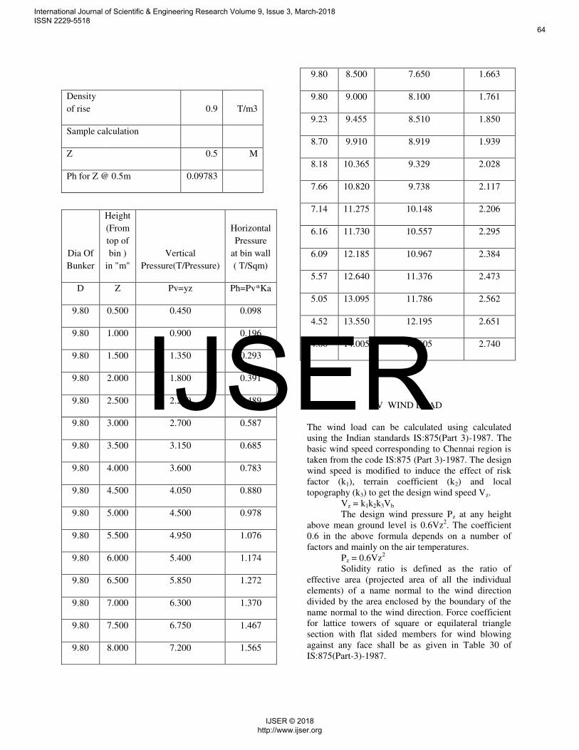
Density
of rise 0.9 T/m3
Sample calculation
Z 0.5 M
Ph for Z @ 0.5m 0.09783
Dia Of
Bunker
Height
(From
top of
bin )
in "m"
Vertical
Pressure(T/Pressure)
Horizontal
Pressure
at bin wall
( T/Sqm)
D Z Pv=yz Ph=Pv*Ka
9.80 0.500 0.450 0.098
9.80 1.000 0.900 0.196
9.80 1.500 1.350 0.293
9.80 2.000 1.800 0.391
9.80 2.500 2.250 0.489
9.80 3.000 2.700 0.587
9.80 3.500 3.150 0.685
9.80 4.000 3.600 0.783
9.80 4.500 4.050 0.880
9.80 5.000 4.500 0.978
9.80 5.500 4.950 1.076
9.80 6.000 5.400 1.174
9.80 6.500 5.850 1.272
9.80 7.000 6.300 1.370
9.80 7.500 6.750 1.467
9.80 8.000 7.200 1.565
9.80 8.500 7.650 1.663
9.80 9.000 8.100 1.761
9.23 9.455 8.510 1.850
8.70 9.910 8.919 1.939
8.18 10.365 9.329 2.028
7.66 10.820 9.738 2.117
7.14 11.275 10.148 2.206
6.16 11.730 10.557 2.295
6.09 12.185 10.967 2.384
5.57 12.640 11.376 2.473
5.05 13.095 11.786 2.562
4.52 13.550 12.195 2.651
4.00 14.005 12.605 2.740
V WIND LOAD
The wind load can be calculated using calculated
using the Indian standards IS:875(Part 3)-1987. The
basic wind speed corresponding to Chennai region is
taken from the code IS:875 (Part 3)-1987. The design
wind speed is modified to induce the effect of risk
factor (k1), terrain coefficient (k2) and local
topography (k3) to get the design wind speed Vz.
Vz = k1k2k3Vb
The design wind pressure Pz at any height
above mean ground level is 0.6Vz2. The coefficient
0.6 in the above formula depends on a number of
factors and mainly on the air temperatures.
Pz = 0.6Vz2
Solidity ratio is defined as the ratio of
effective area (projected area of all the individual
elements) of a name normal to the wind direction
divided by the area enclosed by the boundary of the
name normal to the wind direction. Force coefficient
for lattice towers of square or equilateral triangle
section with flat sided members for wind blowing
against any face shall be as given in Table 30 of
IS:875(Part-3)-1987.
International Journal of Scientific & Engineering Research Volume 9, Issue 3, March-2018 ISSN 2229-5518
64
IJSER © 2018 http://www.ijser.org
IJSER
Force coefficients for lattice towers of
square section with circular members and equilateral
triangle section with circular members are as given in
tables 31 and 32 of IS: 875(Part-3)-1987 respectively.
Table 2 of IS:875(Pa1t-3)-1987 gives the factors to
obtain design wind speed variation with height in
different terrains for different classes of structures
such as class( A,B,C ).
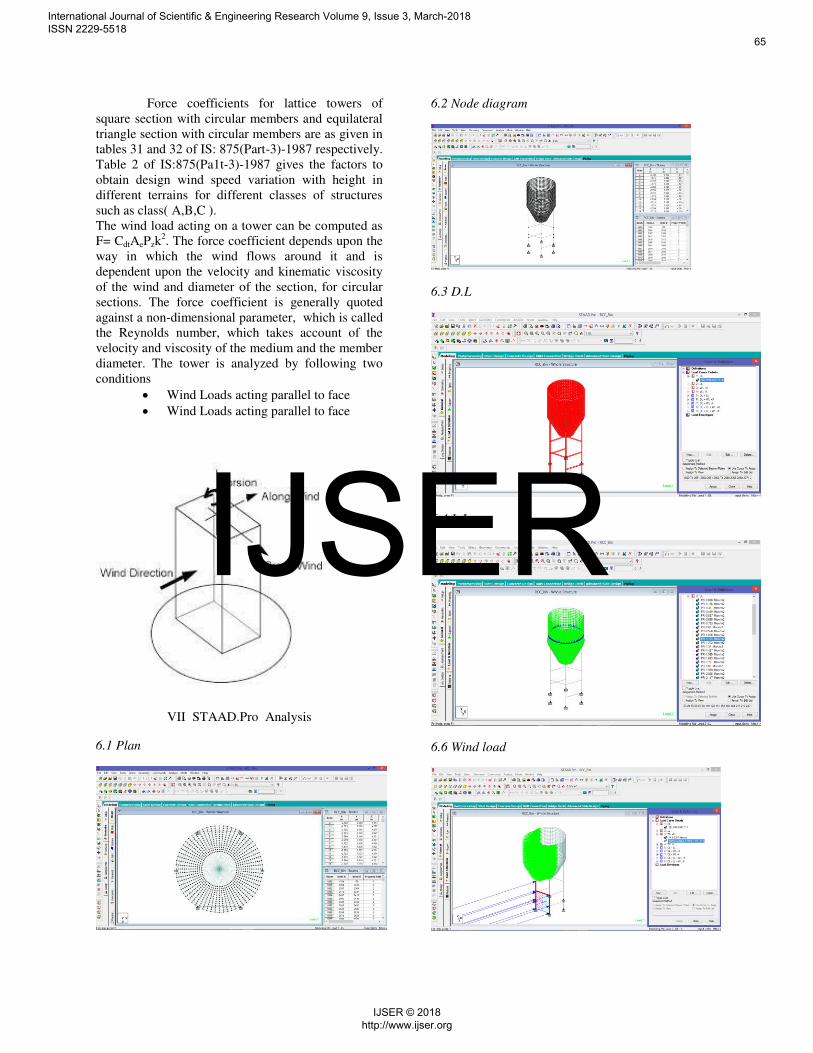
The wind load acting on a tower can be computed as
F= CdtAePzk2. The force coefficient depends upon the
way in which the wind flows around it and is
dependent upon the velocity and kinematic viscosity
of the wind and diameter of the section, for circular
sections. The force coefficient is generally quoted
against a non-dimensional parameter, which is called
the Reynolds number, which takes account of the
velocity and viscosity of the medium and the member
diameter. The tower is analyzed by following two
conditions
Wind Loads acting parallel to face
Wind Loads acting parallel to face
VII STAAD.Pro Analysis
6.1 Plan
6.2 Node diagram
6.3 D.L
6.4 L.L
6.6 Wind load
International Journal of Scientific & Engineering Research Volume 9, Issue 3, March-2018 ISSN 2229-5518
65
IJSER © 2018 http://www.ijser.org
IJSER
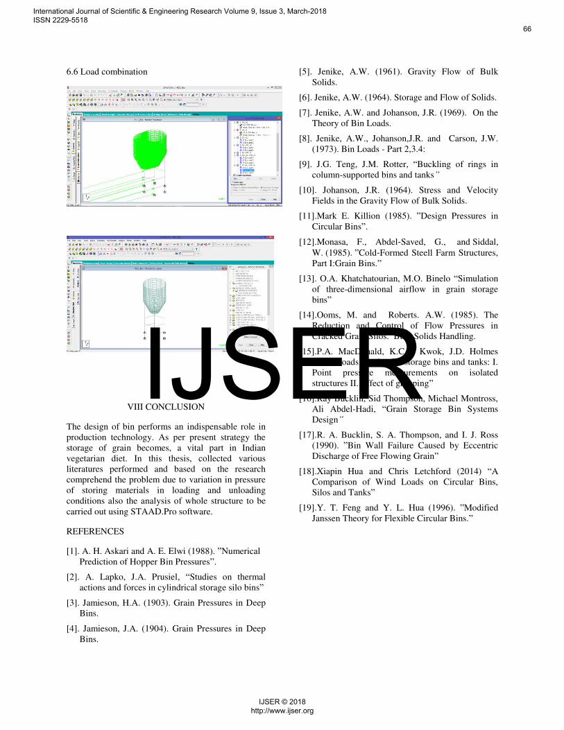
6.6 Load combination
VIII CONCLUSION
The design of bin performs an indispensable role in
production technology. As per present strategy the
storage of grain becomes, a vital part in Indian
vegetarian diet. In this thesis, collected various
literatures performed and based on the research
comprehend the problem due to variation in pressure
of storing materials in loading and unloading
conditions also the analysis of whole structure to be
carried out using STAAD.Pro software.
REFERENCES
[1]. A. H. Askari and A. E. Elwi (1988). ”Numerical
Prediction of Hopper Bin Pressures”.
[2]. A. Lapko, J.A. Prusiel, “Studies on thermal
actions and forces in cylindrical storage silo bins”
[3]. Jamieson, H.A. (1903). Grain Pressures in Deep
Bins.
[4]. Jamieson, J.A. (1904). Grain Pressures in Deep
Bins.
[5]. Jenike, A.W. (1961). Gravity Flow of Bulk
Solids.
[6]. Jenike, A.W. (1964). Storage and Flow of Solids.
[7]. Jenike, A.W. and Johanson, J.R. (1969). On the
Theory of Bin Loads.
[8]. Jenike, A.W., Johanson,J.R. and Carson, J.W.
(1973). Bin Loads - Part 2,3.4:
[9]. J.G. Teng, J.M. Rotter, “Buckling of rings in
column-supported bins and tanks”
[10]. Johanson, J.R. (1964). Stress and Velocity
Fields in the Gravity Flow of Bulk Solids.
[11].Mark E. Killion (1985). ”Design Pressures in
Circular Bins”.
[12].Monasa, F., Abdel‐Saved, G., and Siddal,
W. (1985). ”Cold‐Formed Steell Farm Structures,
Part I:Grain Bins.”
[13]. O.A. Khatchatourian, M.O. Binelo “Simulation
of three-dimensional airflow in grain storage
bins”
[14].Ooms, M. and Roberts. A.W. (1985). The
Reduction and Control of Flow Pressures in
Cracked Grain Silos. Bulk Solids Handling.
[15].P.A. MacDonald, K.C.S. Kwok, J.D. Holmes
“Wind loads on circular storage bins and tanks: I.
Point pressure measurements on isolated
structures II. Effect of grouping”
[16].Ray Bucklin, Sid Thompson, Michael Montross,
Ali Abdel-Hadi, “Grain Storage Bin Systems
Design”
[17].R. A. Bucklin, S. A. Thompson, and I. J. Ross
(1990). ”Bin Wall Failure Caused by Eccentric
Discharge of Free Flowing Grain”
[18].Xiapin Hua and Chris Letchford (2014) “A
Comparison of Wind Loads on Circular Bins,
Silos and Tanks”
[19].Y. T. Feng and Y. L. Hua (1996). ”Modified
Janssen Theory for Flexible Circular Bins.”
International Journal of Scientific & Engineering Research Volume 9, Issue 3, March-2018 ISSN 2229-5518
66
IJSER © 2018 http://www.ijser.org
IJSER


![Ch1b-E4-E5 Civil-Structural Design of RCC Bldg Components Session -2 [Compatibility Mode]](https://img.pdfslide.net/doc/110x75/577cbfcd1a28aba7118e29f0/ch1b-e4-e5-civil-structural-design-of-rcc-bldg-components-session-2-compatibility.jpg)