Embed Size (px)
Citation preview
Journal of Engineering Sciences, Assiut University, Vol. 34, No. 3, pp. 719-732, May 2006
STUDYING THE PERFORMANCE OF A COUNTER-FLOW, VERTICAL EVAPORATIVE HUMIDIFIER
_____________________________________________________________________
Maher A. Mohamed ; Mohamed R. Diab ; Ramadan Bassiouny and Hussein M. Maghrabie Department of Mechanical Power Engineering and Energy ; Faculty of Engineering, Minia University, Minia, Egypt
(Received November 3, 2005 Accepted April 22, 2006)
ABSTRACT– The evaporative humidifier is an energy efficient unit that can be an alternative to other costly cooling systems; depending on climate conditions and building load characteristics. Heat and mass transfer processes occur inside the humidifier as a result of air contact with water spray. The present experimental study aims at investigating some common parameters that have a direct or indirect effect on the evaporative humidifier performance. Among these parameters are: the number of spray nozzles, nozzle arrangements, water-air mass flow rate ratio, and packing material specifications such as: location, z, thickness t, and number of trays.
The results showed that the water-air mass flow rate ratio has a significant effect on the humidifier performance. The results also indicated that an increase in the humidifier saturation efficiency, ε, was noticed as the number of spray nozzles increased for the same water flow rate. However, when keeping the water spray supply pressure constant, a decrease in the saturation efficiency was recorded as the number of spray nozzles increased. Furthermore, placing a packing material inside the humidifier results in enhancing the efficiency due to increasing the mass transfer surface area and air residence time.
INTRODUCTION
Humidity is a major concern for researchers in the air conditioning field due to its important role in many industrial applications and its impact on human comfort. Typical industrial applications of air conditioning are in laboratories, printing plants, the manufacturing of precision parts, textiles, steel, pharmaceuticals, and photographic products. Very recent micro-scale technologies are very sensitive to surrounding environment humidity variation. The application of this technology is obvious in many fields such as communication, data collection, control systems, and office hardware (copier machines, phone systems, computers, and fax machines) [1]. People feel more comfortable when relative humidity (RH) lies between 35-55 % under normal temperature condition. Too low RH results in people discomfort due to dry nose, throat, lips, and skin. High level of humidity causes difficult in breathing, skin itching, a
719
Maher A. Mohamed , et al ________________________________________________________________________________________________________________________________ 720
NOMENCLATURE
m mr n P T t z NZ
mass flow rate, kg/s water-air mass flow rate ratio (mw/ma ) number of packing material trays pressure, kPa. temperature, oC packing material thickness, m tray vertical location, m number of spray nozzles
Subscripts a db dis dp i e max wb w
air dry-bulb discharge dew-point inlet exit maximum wet-bulb Water
Greek symbols
ε saturation efficiency, )
T - T
T - T (
dpdbi,
dbe,dbi, %
and feeling of temperature rise. Feeling of temperature rise means that a person feels warm because of the very low rate of sweat evaporation from the skin surface. So there is a necessity for adjusting air humidity either through air humidification or dehumidification. Air humidification can be attained when water vapor is added to the air increasing the air moisture content. This process can be achieved through evaporative humidifier, steam vaporizer, water atomizer, and air washer. Direct evaporative unit (evaporative humidifier) cools air by direct contact with water, either by an extended wetted surfaces material or with a series of sprays. Indirect evaporative units cool air in a heat exchanger, which transfers heat either to a secondary air stream that has been evaporatively cooled (air to air) or to water that has been evaporatively cooled [2].
In the evaporative humidifier, the moisture is transmitted into the air while flowing through a moistened absorbent material, such as a belt, wicks, or filter. In addition, the wetted material works as filters that help removing incoming pollutants [3]. In all evaporative humidifiers, water vaporizes and the minerals in the water remain in the equipment. This type of coolers is ideal because it can provide high relative humidity at lower temperatures. The evaporative cooler consumes only one fourth of the electrical energy required to operate a mechanical air conditioner or heat pump [4]. The evaporative cooler operates efficiently in hot and dry weathers. However, it has some disadvantages such as, the temperature control in space is not adequate, and the supply air to the humidifier should be from outside
The maximum possible mass flow rate ratio of the water spray and air, mrmax, for different operating conditions is presented in [5]. This ratio is required to obtain the maximum saturation efficiency. The authors showed that for lower values of dimensionless temperature ratios, defined as the ratio between the difference between the inlet and exit water temperatures to the difference between the inlet water temperature and inlet air wet-bulb temperature, the maximum mass flow rate ratio was
STUDYING THE PERFORMANCE OF A COUNTER-FLOW…. ________________________________________________________________________________________________________________________________
721
very high. The results showed that for temperature ratio up to 0.1, the value of the maximum mass flow rate ratio is very high. However, for values greater than 0.4, the required maximum mass flow rate ratio decreased rapidly.
An analytical and experimental study was carried out on the mixing process between air and water droplets in a vertical unit with no internal packing material. The results showed that at any height, all sprayed droplets were not at the same temperature. The arrangement of spray nozzles has a direct effect on the humidifier performance. Hence, care is required in determining the layout of the nozzles to insure as little as possible of the water spray migration to the wall allowing almost one percent of the total water flow to be carried up to the eliminator [6].
The shape effect of the packing material on the heat transfer was marginal [7]. It was noticed that placing packing material into the airflow passage yields about a three-time increase in the wall to air heat transfer rate compared to that of an empty duct [7].
Surfaces of the packing material with reduced dynamic contact angles would increase the performance in terms of cooling effectiveness in the direct evaporative cooling system. However, only those surfaces with significant wicking capacity could increase this performance depending on water flow rate. The increase is significant for certain value of water mass flow rate and then the increase is symptomatic to a high value [8].
Previous available published literatures interested in water droplets-air interaction process revealed the shortage of having a thorough and comprehensive study about the evaporative humidifier performance. Most of the previous work has tackled this interaction process from the cooling tower point of view analysis. Theoretically, both cooling tower and humidifier are devices with an air-water interaction process. However, the function of the cooling tower is to cool water, as a working fluid, on the expense of rejecting its sensible and latent heat to the air. But the humidifier aims at substituting the high sensible load in the air by a latent load from water droplets evaporation, resulting in air temperature decrease. Some researchers have studied the enthalpy and moisture content variation; others have considered the water spray and packing material effect on the evaporative humidifier performance. The effect of mass flow ratio on air dry-bulb temperature and moisture content change has been studied as well. Some others have considered the spray water pressure, and droplet size on heat and mass transfer process.
It is important for the HVAC engineer as well as the designer to have a thorough insight into the different parameters that could affect the performance of the humidifier.
EXPERIMENTAL SET-UP Figure 1 shows a general layout of the experimental set-up. The experimental set-up mainly includes: a blower, an air pre-heater, a spray humidifier, and duct system equipped with the appropriate measurements. The blower is a radial type with a constant speed of 2890 rpm and a maximum air delivery of 0.1m3/s. It is driven by a single phase AC electric motor of 1.1 kW (1.5hp). The air pre-heater consists of an electric coil shaped inside a copper tube. Its total power is 3000 W. The shape insures having two planes normal to the air flow and one plane parallel to the flow.

Maher A. Mohamed , et al ________________________________________________________________________________________________________________________________ 722
`
Fig
. 1:
Layo
ut o
f the
exp
erim
enta
l set
-up.
STUDYING THE PERFORMANCE OF A COUNTER-FLOW…. ________________________________________________________________________________________________________________________________
723
The spray humidifier consists of a transparent chamber, a bank of spray nozzles, water tank equipped with thermostatic water heaters, centrifugal water pump, and eliminators. The transparent chamber is made of glass walls mounted in an alumetal frame. The dimensions of this chamber are 0.5×0.5×0.5 m3. A number of packing material trays can be variably mounted inside the chamber. The trays can be easily moved up and down through vertical slots in two side walls of the transparent chamber to adjust the interspaces between the trays. The spray nozzle (or nozzles) connected to the pump discharge pipe is (are) installed at the upper section of the humidifier above the upper tray.
The pump is a centrifugal type of 0.6 kW (0.75hp) with a constant speed of 2800 rpm. It is driven by a single-phase AC 220 V electric motor. It provides a manometeric head of 44 to 12 m with a corresponding discharge of 10 to 40 l /min.
A fine deck packing material made of recycled plastic with certain configurations was used inside the spray humidifier. This deck is manufactured from PVC sheets arranged all together to form a corrugated shape. The porosity of this packing material measured in the present study was 97%. The surface area per unit volume was 1.922 m2/m3 based on calculation.
The air supply duct was made of 0.001m thick galvanized steel sheets and coated with anti-rust paint. The aspect ratio of this duct is one (0.25×0.25 m2). A bell-like-shape inlet section was connected to the blower suction side through a circular duct 0.15 m in diameter and 0.4 m in length. To reduce the duct heat loss (or gain) with its surrounding, a blanket of glass wool of thickness 0.03 m was wrapped around the duct walls and humidifier’s side walls.
Dry and wet-bulb temperature measurements were carried out along the duct before and after each unit of the system using type K-thermocouples. Air temperature and velocity patterns at a cross-section of a non-circular duct are non-uniform. Therefore, an average dry-bulb temperature across the duct was obtained by placing and parallel connecting four junctions of thermocouples at different four places in the duct cross-section area. In measuring wet-bulb temperatures, the thermocouples were placed downstream of the dry-bulb thermocouples to avoid the effect of evaporated water from the wetted wick around the junction. Thermocouples used to measure wet–bulb temperatures were installed in places where a proper air velocity over the wetted junction is guaranteed. The wet-bulb thermocouples were placed in the downstream of the dry-bulb thermocouple to avoid the effect of vaporization on recording the dry-bulb temperature. Inside the humidifier the air dry-bulb temperature distributions were measured, in addition to the inlet and exit dry and wet bulb temperatures to locate the process of air humidification on the psychrometric chart.
There was a configuration for measuring the wet-bulb temperature. A small plastic bottle, filled with water and raised at a certain distance above the junction, is connected to a small plastic tube that is connected to a small copper tube through which a cotton wick containing the junction was inserted. The small copper tube with the junction extended outside is placed inside the supply duct and downstream of the dry-bulb junction.
All necessary properties of air can be directly known from the psychometric chart based on determining these two independent properties, the dry and wet-bulb temperatures.
Maher A. Mohamed , et al ________________________________________________________________________________________________________________________________ 724
The supply airflow rate was measured using a standard airflow nozzle (0.038 m throat diameter). The nozzle was constructed and installed in accordance with ASHRAE standards. Because the duct is not circular, four static pressure tabs were placed, at a standard distance, upstream and downstream of the nozzle plate. The pressure drop was measured using a water manometer having one side connected to a manifold of the four static pressure tabs in the upstream and the other side similarly connected downstream. The velocity of air passing through the nozzle was calculated based on the measured pressure drop across the nozzle panel. The Experimental Procedure
The test rig is left to run for approximately 45 minutes before recording any measurement. The outdoor air conditions (Tdb, Twb) were measured and located on the psychrometric chart. At the same time, inlet and exit conditions to the humidifier (Tdb, Twb) and airflow rate were measured. The spray water temperature was controlled using two heaters equipped with adjusted thermostats. A gauge pressure indicator on the pump discharge tube was used to measure the pump discharge pressure before water flowing to the spray nozzle (s). Three meshed-trays, equipped with nine thermocouple junctions each, were placed inside the humidifier at different vertical distance to measure the air temperature distribution. These junctions were shielded using plastic tubes to isolate the junctions from the falling water droplets.
A by-pass valve is mounted at the pump discharge line. This valve is used to control the water discharge pressure. This pressure allows a certain flow rate to pass to the nozzles. Having a constant discharge pressure and changing the number of nozzles results in having a more fine droplets and larger cone angle in the case of single nozzle than in the case of four nozzles. However, a constant water flow rate for all number of nozzles results in having a larger contact area in the case of the four nozzles than in the case of the single nozzle.
RESULTS AND DISCUSSION
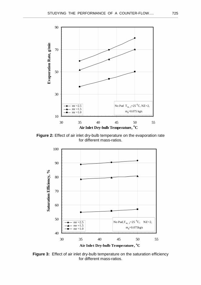
Figure 2 shows the effect of inlet air temperature variation on the evaporation rate for three different water-air mass flow rate ratios (mr). The evaporation rate is defined as the difference between exit and inlet moisture content multiplied by the air flow rate. The figure illustrates that there is a similar trend for the dependence of evaporation rate on the air dry-bulb temperature. There is almost a linear increase in the evaporation rate as the air inlet dry-bulb temperature increased. A quantitative increase in the evaporation for the higher mass ratio was noticed compared to the lower mass ratio. This would indicate that, for the same inlet air flow, increasing the mass ratio leads to an increase in the water spray contact area and accordingly this enhances the mass transfer process.
The saturation efficiency is defined as the ratio of the actual evaporation rate to the maximum possible evaporation rate. This efficiency, as shown in Figure 3, was slightly affected by the air inlet temperature compared to the mass ratio variation effect. The slight change is due to the relative relation of the evaporation rate to the maximum possible evaporation in calculating the saturation efficiency.
STUDYING THE PERFORMANCE OF A COUNTER-FLOW…. ________________________________________________________________________________________________________________________________
725
No Pad Tw, i=25 oC, NZ=2,
ma=0.075 kg/s
10
30
50
70
90
30 35 40 45 50 55
Air Inlet Dry-bulb Temperature, oC
Eva
pora
tion
Rat
e, g
/min
mr =2.5 mr =1.5 mr =1.0
Figure 2: Effect of air inlet dry-bulb temperature on the evaporation rate
for different mass-ratios.
No Pad,Tw, i=25 oC, NZ=2,
ma=0.075kg/s
40
50
60
70
80
90
100
30 35 40 45 50 55
Air Inlet Dry-bulb Temperature, oC
Satu
ratio
n E
ffic
ienc
y, %
mr =2.5 mr =1.5 mr =1.0
Figure 3: Effect of air inlet dry-bulb temperature on the saturation efficiency for different mass-ratios.
Maher A. Mohamed , et al ________________________________________________________________________________________________________________________________ 726
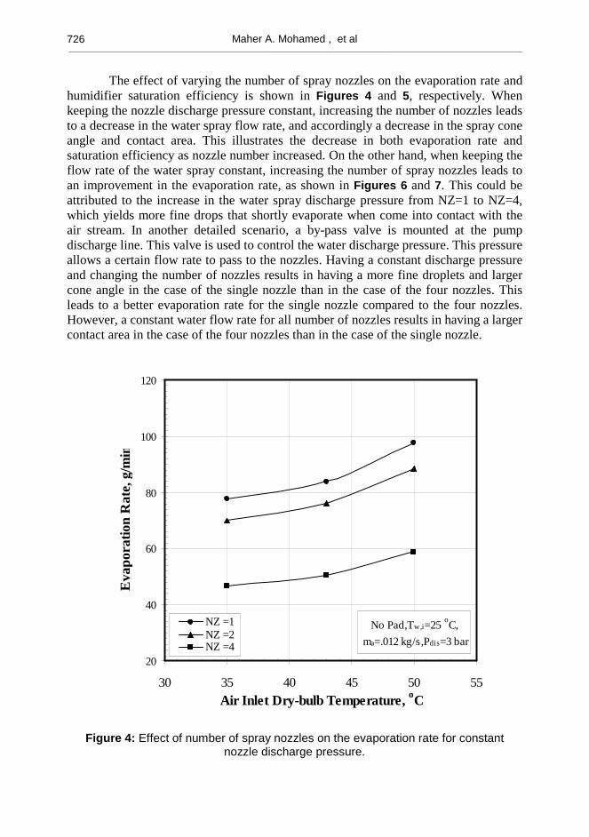
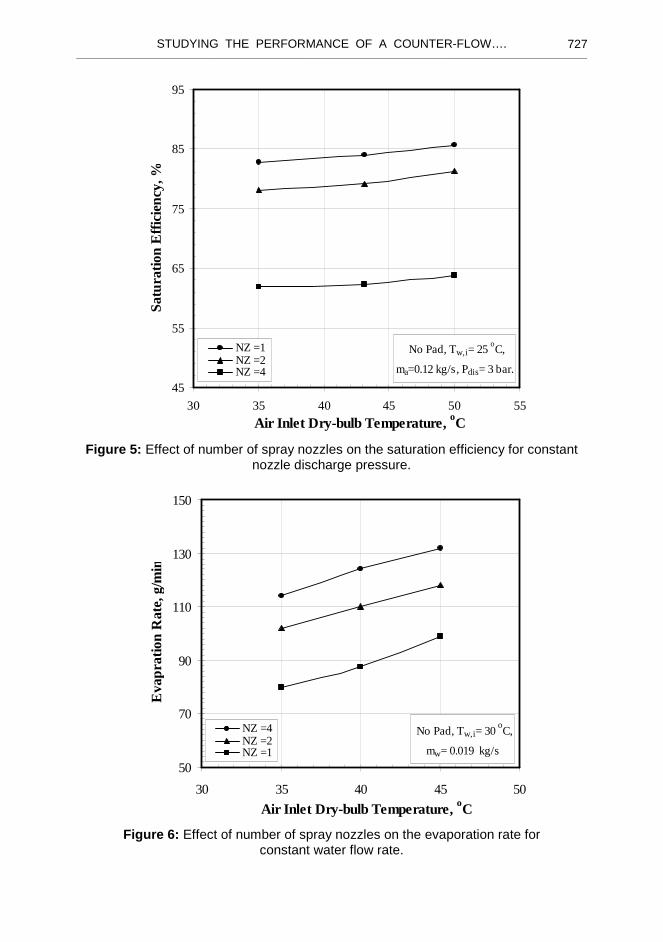
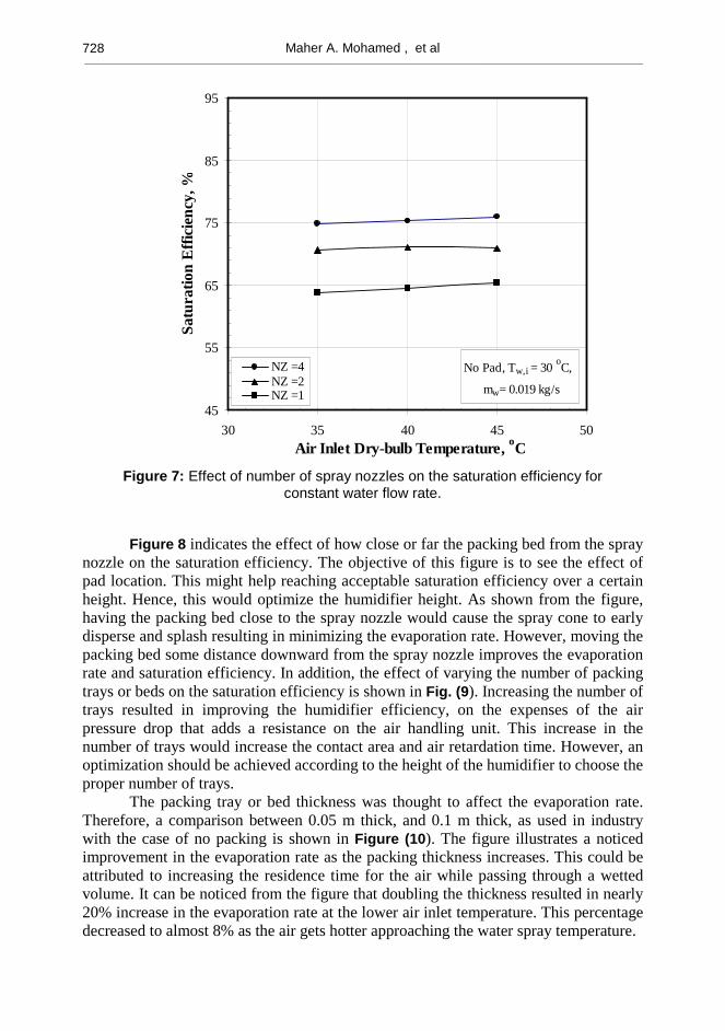
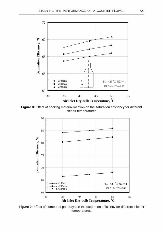
The effect of varying the number of spray nozzles on the evaporation rate and humidifier saturation efficiency is shown in Figures 4 and 5, respectively. When keeping the nozzle discharge pressure constant, increasing the number of nozzles leads to a decrease in the water spray flow rate, and accordingly a decrease in the spray cone angle and contact area. This illustrates the decrease in both evaporation rate and saturation efficiency as nozzle number increased. On the other hand, when keeping the flow rate of the water spray constant, increasing the number of spray nozzles leads to an improvement in the evaporation rate, as shown in Figures 6 and 7. This could be attributed to the increase in the water spray discharge pressure from NZ=1 to NZ=4, which yields more fine drops that shortly evaporate when come into contact with the air stream. In another detailed scenario, a by-pass valve is mounted at the pump discharge line. This valve is used to control the water discharge pressure. This pressure allows a certain flow rate to pass to the nozzles. Having a constant discharge pressure and changing the number of nozzles results in having a more fine droplets and larger cone angle in the case of the single nozzle than in the case of the four nozzles. This leads to a better evaporation rate for the single nozzle compared to the four nozzles. However, a constant water flow rate for all number of nozzles results in having a larger contact area in the case of the four nozzles than in the case of the single nozzle.
No Pad,Tw,i=25 o
C,
ma=.012 kg/s,Pdis=3 bar
20
40
60
80
100
120
30 35 40 45 50 55
Air Inlet Dry-bulb Temperature, oC
Eva
pora
tion
Rat
e, g
/min
NZ =1NZ =2NZ =4
Figure 4: Effect of number of spray nozzles on the evaporation rate for constant nozzle discharge pressure.
STUDYING THE PERFORMANCE OF A COUNTER-FLOW…. ________________________________________________________________________________________________________________________________
727
No Pad, Tw,i= 25 oC,
ma=0.12 kg/s, Pdis= 3 bar.
45
55
65
75
85
95
30 35 40 45 50 55
Air Inlet Dry-bulb Temperature, oC
Satu
ratio
n E
ffic
ienc
y, %
NZ =1NZ =2NZ =4
Figure 5: Effect of number of spray nozzles on the saturation efficiency for constant
nozzle discharge pressure.
No Pad, Tw,i= 30 oC,
mw= 0.019 kg/s
50
70
90
110
130
150
30 35 40 45 50
Air Inlet Dry-bulb Temperature, oC
Eva
prat
ion
Rat
e, g
/min
NZ =4NZ =2NZ =1
Figure 6: Effect of number of spray nozzles on the evaporation rate for
constant water flow rate.
Maher A. Mohamed , et al ________________________________________________________________________________________________________________________________ 728
No Pad, Tw,i = 30 oC,
mw= 0.019 kg/s
45
55
65
75
85
95
30 35 40 45 50 Air Inlet Dry-bulb Temperature, oC
Satu
ratio
n E
ffic
ienc
y, %
NZ =4NZ =2NZ =1
Figure 7: Effect of number of spray nozzles on the saturation efficiency for
constant water flow rate.
Figure 8 indicates the effect of how close or far the packing bed from the spray nozzle on the saturation efficiency. The objective of this figure is to see the effect of pad location. This might help reaching acceptable saturation efficiency over a certain height. Hence, this would optimize the humidifier height. As shown from the figure, having the packing bed close to the spray nozzle would cause the spray cone to early disperse and splash resulting in minimizing the evaporation rate. However, moving the packing bed some distance downward from the spray nozzle improves the evaporation rate and saturation efficiency. In addition, the effect of varying the number of packing trays or beds on the saturation efficiency is shown in Fig. (9). Increasing the number of trays resulted in improving the humidifier efficiency, on the expenses of the air pressure drop that adds a resistance on the air handling unit. This increase in the number of trays would increase the contact area and air retardation time. However, an optimization should be achieved according to the height of the humidifier to choose the proper number of trays.
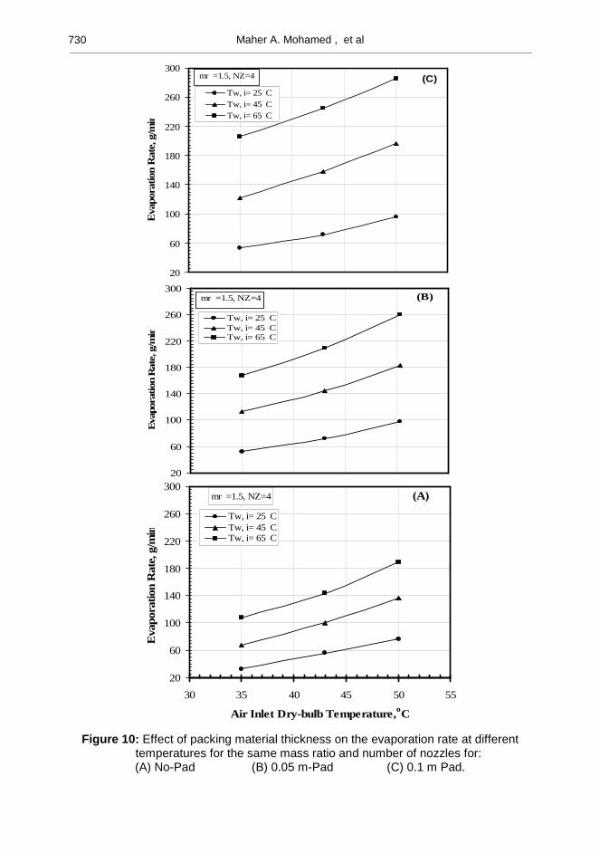
The packing tray or bed thickness was thought to affect the evaporation rate. Therefore, a comparison between 0.05 m thick, and 0.1 m thick, as used in industry with the case of no packing is shown in Figure (10). The figure illustrates a noticed improvement in the evaporation rate as the packing thickness increases. This could be attributed to increasing the residence time for the air while passing through a wetted volume. It can be noticed from the figure that doubling the thickness resulted in nearly 20% increase in the evaporation rate at the lower air inlet temperature. This percentage decreased to almost 8% as the air gets hotter approaching the water spray temperature.
STUDYING THE PERFORMANCE OF A COUNTER-FLOW…. ________________________________________________________________________________________________________________________________
729
Tw, i =35 oC, NZ =4 ,
mr =1.5, t =0.05 m
60
63
66
69
72
30 35 40 45 50 55
Air Inlet Dry-bulb Temperature, 0C
Sat
urat
ion
Eff
icie
ncy,
%
Z=0.8 mZ=0.5 mZ=0.3 m
Figure 8: Effect of packing material location on the saturation efficiency for different
inlet air temperatures.
Tw, i =35 oC, NZ = 4,
mr =1.5, t =0.05 m
60
65
70
75
80
85
90
30 35 40 45 50 55
Air Inlet Dry-bulb Temperatutre, oC
Satu
ratio
n E
ffic
ienc
y, %
n=1 Padn=2 Padsn=3 Pads
Figure 9: Effect of number of pad trays on the saturation efficiency for different inlet air
temperatures.
z
Maher A. Mohamed , et al ________________________________________________________________________________________________________________________________ 730
Figure 10: Effect of packing material thickness on the evaporation rate at different temperatures for the same mass ratio and number of nozzles for:
(A) No-Pad (B) 0.05 m-Pad (C) 0.1 m Pad.
20
60
100
140
180
220
260
300
Eva
pora
tion
Rat
e, g
/min
Tw, i= 25 CTw, i= 45 CTw, i= 65 C
mr =1.5, NZ=4 (B)
20
60
100
140
180
220
260
300 (C)
Eva
pora
tion
Rat
e, g
/min
Tw, i= 25 CTw, i= 45 CTw, i= 65 C
mr =1.5, NZ=4
mr =1.5, NZ=4
20
60
100
140
180
220
260
300
30 35 40 45 50 55
Air Inlet Dry-bulb Temperature,oC
Eva
pora
tion
Rat
e, g
/min
Tw, i= 25 CTw, i= 45 CTw, i= 65 C
(A)
STUDYING THE PERFORMANCE OF A COUNTER-FLOW…. ________________________________________________________________________________________________________________________________
731
CONCLUSIONS The present study has focused on investigating some of the parameters that are
expected to affect the evaporative humidifier performance. Some significant conclusions are drawn out from the analysis of the results as follows:
1. Increasing the water spray flow rate and its temperature significantly affect the humidifier performance compared with preheating the inlet air temperature.
2. The humidifier saturation efficiency is increased as the number of spray nozzles increased for the same water flow rate. However, when keeping the water supply pressure constant, a reverse effect was noticed when increasing the number of spray nozzles.
3. Increasing the tray thickness or the number of packing trays resulted in improving the humidifier performance. However, placing a tray close to the spray nozzle would lead to spray splash and disperse causing a decrease in the evaporation rate, and accordingly the saturation efficiency.
REFERENCES
[1] Arora, S. C., and Domkundwar. S. 1992, “ Refrigeration and Air Conditioning”, 3 rd edition, Chapter 24 pp.24.17-24.30.
[2] ASHRAE Handbook of Fundamentals, 1998, American Society of Heating, Refrigerating, and Air–Conditioning Engineers, Atlanta, chapter 19, pp 1-20
[3] Pacscod, D., 1979,“ A Heat Exchanger for Energy Saving in an Air Conditioning Plant,” ASHRAE Transactions, 85(2), pp. 238-251.
[4] Jameel-ur-Rehman Khan, and Syed M. Zubair, 2001, “An Improved Design and Rating Analyses of Counter Flow Wet Cooling Towers,” Journal of Heat Transfer, Trans. ASME, Vol. 123, , pp. 770-778.
[5] Kau, F. W. and Alexander, D., 1976 ,“ Heat Transfer Characteristics of Pours Media” chapter 7, pp 84-97.
[6] Ciofalo, M., Stasiek, J. and Collins, M. W., 1996, “Investigation of Flow and Heat Transfer in Corrugated Passage”, II Numerical Simulation,” International Journal. of Heat Mass Transfer, Vol. 39/1, , pp. 165-192.
[7] ASHRAE Handbook of System and Equipment, 1999, American Society of Heating, Refrigerating, and Air–Conditioning Engineers, Inc, New Handbook, Chapter 22.
[8] Tibin, A. W., and Robert, L. R., 1996, “ Surface Wettability Effect on an Indirect Evaporative Cooling System”, ASHRAE Transaction, Vol 102, No 1, pp. 427-432.

Maher A. Mohamed , et al ________________________________________________________________________________________________________________________________ 732
درا� أداء �ط� ��ي رأ� ذو ��ن ����
دي ����� �� � وا��� ���� أن ���ن ���� ا���)�%# ا��#ط& ا�%$#ي و"�ة ! ءة ���#وف ا��*/�0 و/�.- ا�,�� +� ا��%*(� 0ت ا��2ل ا�,#ارة . �%#�� أ/#ى ط2%��7 8��
. وا����� دا/� ا��#ط& !*�0=� >"��ك ا�:�اء �#زاز ا��ء
���� أن ���ن �: �0BC# ا����:�ف ا��را�A ا��=#�%�0 ا�,��0 إ�( +,- �)? ا�)�ا<� 7�( أداء ا��#ط& #D%> #0E أو #D�7د أ��اق ا�#زاز، �#�0& : <� ��0 ھGه ا�)�ا<�. <%ن ا��ء إ�( ا�:�اء و�#A �%K� ،دا/� ا��#ط&، ا���اق :(L�> �M> �N,ت <�اد ا� Oا�>
�N,و�7د ر+�ف <�اد ا� ،:��$� .
ن ا��ء إ�( ا�:�اء �: �0BC# ذو د>�� 7�( أداء ا��#ط&�#A �%K� أن Q.. أظ:#ت ا�*�دة �7د أ��اق ا�#زاز �S� �0 ��#ا(%N�ءة ا��#ط& ا� ! �+ �K,� ك أوT,L ا�*�.Q أن ھ*�!
ن ا��ءأ/Gا +� ا>7�%�#A ��ر B%�ت !� . U"�� ،ءت VWL رزاز ا��%B )�و��� 7*� ا�, ظ 7ءة ا��#ط& ا��X> �0(%N ز�دة �7د ا���اق ! �+ - *� . �N" د <�اد�Yو ،Zذ� )�7]وة 7
�K,� )ن ا�:�اء +�دا/� ا��#ط& �\دى إ���A �>وز ��"� ا��2ل ا���K> دة .ا�� ءة ��0=� ز�