Embed Size (px)
Citation preview

STX 165 / STX 165R Installation Manual
3700 Osuna Rd NE, Suite 711Albuquerque, NM 87109www.sandia.aero 306100-00
This document and the information contained herein is the proprietary data of SANDIA aerospace Corporation. No part of this document may be transmitted, reproduced, or copied in any form or by any means without the prior written consent of SANDIA aerospace. Due to SANDIA aerospace’s continued product and quality improvement programs, information contained in this document is subject to change without prior noticeCopyright 2010 SANDIA aerospace Corporation, All right rights reserved. Printed in USA
Information Subject To Export Control Laws
Record of RevisionsRevision Date Description Approval
-1 20120222 DRN 402 L. Harrison-2 20120308 ECN 3884 L. Harrison-3 20130311 ECN 3916 L. Harrison-4 20130926 ECN 4004 L. Harrison-5 20140303 ECN 4010 L. Harrison
1
Table of Contents
306100-002
Record of Revisions ....................................................................................................................................1Table of Contents .......................................................................................................................................2List of Illustrations .....................................................................................................................................3Section 1 General Description ...................................................................................................................4
1.1 Introduction ....................................................................................................................41.2 STX 165 / STX 165R Product Description ....................................................................41.3 Technical Characteristics ...............................................................................................41.3.1 Physical Characteristics .................................................................................................41.3.1.1 STX 165 Panel Mount ...................................................................................................41.3.1.2 STX165R Remote Mount Unit ......................................................................................41.3.1.3 STP78 OAT Probe ..........................................................................................................41.3.2 Electrical Characteristics - STX 165 and STX 165R .....................................................41.3.3 Operational Chacteristics ...............................................................................................51.3.3.1 STX 165 Panel Mount ...................................................................................................51.3.3.2 STX 165R Remote Mount .............................................................................................51.3.3.3 ST 78 OAT Probe ...........................................................................................................51.3.4 Certification ....................................................................................................................5
Environmental Qualifaction Form - STX 165 .........................................................................................6Environmental Qualifaction Form - STX 165 R .....................................................................................7Section 2 Installation Considerations .......................................................................................................8
2.1 General ...........................................................................................................................82.2 Mounting Considerations ...............................................................................................82.2.1 STX 165 Panel Mount ...................................................................................................82.2.1.1 Optional 3” Adapter Plate ..............................................................................................82.2.2 STX 165R Remote Mount .............................................................................................82.3 Cooling ...........................................................................................................................8
Section 2 Installation Procedures .............................................................................................................93.1 General ...........................................................................................................................93.2 Equipment Required ......................................................................................................93.2.1 STX 165 Panel Mount ...................................................................................................9 3.2.1.1 Supplied .........................................................................................................................93.2.1.2 Required but not supplied ..............................................................................................93.2.2 STX 165R Remote Mount .............................................................................................93.2.2.1 Supplied .........................................................................................................................93.2.2.1 Required but not supplied ..............................................................................................93.2.2.3 Optional ..........................................................................................................................93.3 Electrical ......................................................................................................................103.4 Aircraft mounting .........................................................................................................103.4.1 STX 165 .......................................................................................................................103.5.2 STX 165R ....................................................................................................................113.4.2.1 Mounting Tray .............................................................................................................113.4.2.2 Hard Mounting without Tray .......................................................................................123.5 Static Port Connection .................................................................................................133.6 Elecrical Connections ..................................................................................................133.6.1 STX 165 Panel Mount ................................................................................................133.6.2 STX 165R Remote Mount ...........................................................................................13
List of Illustrations
3.6.3 Outside Air Temp Probe ...............................................................................................143.6.4 Antenna Connector ......................................................................................................143.7 Connector Pin Out ........................................................................................................163.7.1 STX 165 Panel Mount .................................................................................................163.7.2 STX 165R Remote Mount ...........................................................................................173.8 Calibration Procedures -STX 165 Panel Mount ..........................................................183.9 InstallationConfigurations-STX165PanelMount ...................................................183.9.1 OAT Sensor ..................................................................................................................183.9.2 OAT Correction ............................................................................................................193.9.3 RS 232 BAUD Rate Selection .....................................................................................193.9.4 MAX Relpy Rate .........................................................................................................193.9.5 Exit Installer Set Up Mode ..........................................................................................193.10 User Set Up Mode ........................................................................................................193.10.1 Altitude Unit ................................................................................................................193.10.2 Temperature Unit .........................................................................................................203.10.3 Icing Alert Temp ..........................................................................................................203.10.4 EFT Start ......................................................................................................................203.10.5 Auto Mode C Alt ..........................................................................................................203.10.6 Min Brightness .............................................................................................................203.10.7 Default VFR Code .......................................................................................................213.10.8 Exit User Set Up Mode ................................................................................................213.11 Continued Airwortiness ...............................................................................................213.11.1 STX 165 Panel Mount .................................................................................................213.11.2 STX 165R Remote Mount ...........................................................................................20
Figure 3-1 Panel Cut Out Dimensions .....................................................................................10Figure 3-2 STX 165 Top Dimensions ......................................................................................11Figure 3-3 Remote Mounting Tray Dimensions ......................................................................11Figure 3-4 Remote Unit Dimensions w/out tray ......................................................................12Figure 3-5 J2/J3 Connector Wiring ..........................................................................................13Figure 3-6 J2/J3 Connector Hood Assembly ...........................................................................13Figure 3-7 STP 78 OAT Probe Dimensions .............................................................................14Figure 3-8 STP 78 OAT Probe Mounting ................................................................................14Figure 3-9 Antenna SMA Assembly ........................................................................................15 Figure 3-10 STX 165 Rear View ...............................................................................................15
3
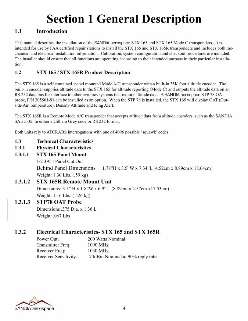
Section 1 General Description1.1 Introduction
This manual describes the installation of the SANDIA aerospace STX 165 and STX 165 Mode C transponders. It is intendedforusebyFAAcertifiedrepairstationstoinstalltheSTX165andSTX165Rtranspondersandincludesbothme-chanicalandelectricalinstallationinformation.Calibration,systemconfigurationandcheckoutproceduresareincluded.The installer should ensure that all functions are operating according to their intended purpose in their particular installa-tion.
1.2 STX 165 / STX 165R Product Description
The STX 165 is a self contained, panel mounted Mode A/C transponder with a built-in 35K foot altitude encoder. The built-in encoder supplies altitude data to the STX 165 for altitude reporting (Mode C) and outputs the altitude data on an RS 232 data bus for interface to other avionics systems that require altitude data. A SANDIA aerospace STP 78 OAT probe, P/N 305561-91 can be installed as an option. When the STP 78 is installed, the STX 165 will display OAT (Out-side Air Temperature), Density Altitude and Icing Alert.
The STX 165R is a Remote Mode A/C transponder that accepts attitude data from altitude encoders, such as the SANDIA SAE 5-35, in either a Gilham Grey code or RS 232 format.
BothunitsrelytoATCRABSinterrogationswithoneof4096possible‘squawk’codes.
1.3 Technical Characteristics1.3.1 Physical Characteristics1.3.1.1 STX 165 Panel Mount 1/2 3ATI Panel Cut Out Behind Panel Dimensions 1.78”H x 3.5”W x 7.34”L (4.52cm x 8.89cm x 18.64cm) Weight:1.30Lbs.(.59kg)1.3.1.2 STX 165R Remote Mount Unit Dimensions: 3.5” H x 1.8”W x 6.9”L (8.89cm x 4.57cm x17.53cm) Weight:1.16Lbs.(.526kg)1.3.1.3 STP78 OAT Probe Dimensions .375 Dia. x 1.36 L Weight: .067 Lbs
1.3.2 Electrical Characteristics- STX 165 and STX 165R Power Out: 200 Watts Nominal Transmitter Freq: 1090 MHz Receiver Freq: 1030 MHz Receiver Sensitivity: -74dBm Nominal at 90% reply rate
4
306100-00
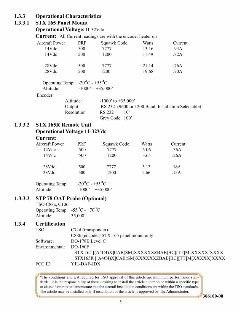
1.3.3 Operational Characteristics1.3.3.1 STX 165 Panel Mount Operational Voltage: 11-32Vdc Current: All Current readings are with the encoder heater on AircraftPower PRF SquawkCode Watts Current 14Vdc 500 7777 13.16 .94A 14Vdc 500 1200 11.49 .82A 28Vdc 500 7777 21.14 .76A 28Vdc 500 1200 19.68 .70A
Operating Temp: -20oC - +55oC Altitude: -1000’ - +35,000’
1.3.3.2 STX 165R Remote Unit Operational Voltage 11-32Vdc Current: AircraftPower PRF SquawkCode Watts Current 14Vdc 500 7777 5.06 .36A 14Vdc 500 1200 3.65 .26A 28Vdc 500 7777 5.12 .18A 28Vdc 500 1200 3.66 .13A
Operating Temp: -20oC - +55oC Altitude: -1000’ - +35,000’
1.3.3.3 STP 78 OAT Probe (Optional) TSO C88a, C106 Operating Temp: -55oC - +70oC Altitude: 35,000’
1.3.4 Certification TSO: C74d (transponder) C88b (encoder) STX 165 panel mount only Software: DO-178B Level C Environmental: DO-160F STX 165 [(A4C4)X]CAB(SM)XXXXXXZBAB[BC][TT]M[XXXXX]XXXX STX165R [(A4C4)X]CAB(SM)XXXXXXZBAB[BC][TT]M[XXXXX]XXXX
FCC ID YJL-DAF-JDX
“The conditions and test required for TSO approval of this article are minimum performance stan-dards.Itistheresponsibilityofthosedesiringtoinstallthearticleeitheronorwithinaspecifictypeor class of aircraft to demonstrate that the aircraft installation conditions are within the TSO standards. The article may be installed only if installation of the article is approved by the Administrator.
5
Encoder: Altitude: -1000’ to +35,000’ Output: RS 232 (9600 or 1200 Baud, Installation Selectable) Resolution RS 232 10’ Grey Code 100’
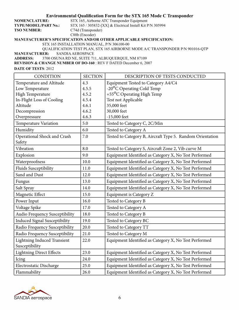
EnvironmentalQualificationFormfortheSTX165ModeCTransponderNOMENCLATURE: STX 165, Airborne ATC Transponder EquipmentTYPE/MODEL/PART No.: STX 165 / 305832-[XX] & Electrical Install Kit P/N 305994TSO NUMBER: C74d (Transponder) C88b (Encoder)MANUFACTURER’S SPECIFICATION AND/OR OTHER APPLICABLE SPECIFICATION: STX 165 INSTALLATION MANUAL, P/N 306100-00
QUALIFICATION TEST PLAN, STX 165 AIRBORNE MODE A/C TRANSPONDER P/N 901016-QTPMANUFACTURER: SANDIA AEROSPACEADDRESS: 3700 OSUNA RD NE, SUITE 711, ALBUQUERQUE, NM 87109REVISION & CHANGE NUMBER OF DO-160 : REV F DATED December 6, 2007DATE OF TESTS: 2012
6
CONDITION SECTION DESCRIPTION OF TESTS CONDUCTEDTemperature and AltitudeLow TemperatureHigh TemperatureIn-Flight Loss of CoolingAltitudeDecompressionOverpressure
4.34.5.54.5.24.5.44.6.14.6.24.6.3
Equipment Tested to Category A4/C4-20oC Operating Cold Temp+55oC Operating High TempTest not Applicable35,000 feet30,000 feet-15,000 feet
Temperature Variation 5.0 Tested to Category C, 2C/MinHumidity 6.0 Tested to Category AOperational Shock and Crash Safety
7.0 Tested to Category B, Aircraft Type 5. Random Orientation
Vibration 8.0 Tested to Category S, Aircraft Zone 2, Vib curve MExplosion 9.0 Equipment Identified as Category X, No Test PerformedWaterproofness 10.0 Equipment Identified as Category X, No Test PerformedFluids Susceptibility 11.0 Equipment Identified as Category X, No Test PerformedSand and Dust 12.0 Equipment Identified as Category X, No Test PerformedFungus 13.0 Equipment Identified as Category X, No Test PerformedSalt Spray 14.0 Equipment Identified as Category X, No Test PerformedMagnetic Effect 15.0 Equipment is Category ZPower Input 16.0 Tested to Category BVoltage Spike 17.0 Tested to Category AAudio Frequency Susceptibility 18.0 Tested to Category BInduced Signal Susceptibility 19.0 Tested to Category BCRadio Frequency Susceptibility 20.0 Tested to Category TTRadio Frequency Susceptibility 21.0 Tested to Category MLightning Induced Transient Susceptibility
22.0 Equipment Identified as Category X, No Test Performed
Lightning Direct Effects 23.0 Equipment Identified as Category X, No Test PerformedIcing 24.0 Equipment Identified as Category X, No Test PerformedElectrostatic Discharge 25.0 Equipment Identified as Category X, No Test PerformedFlammability 26.0 Equipment Identified as Category X, No Test Performed
7306100-00
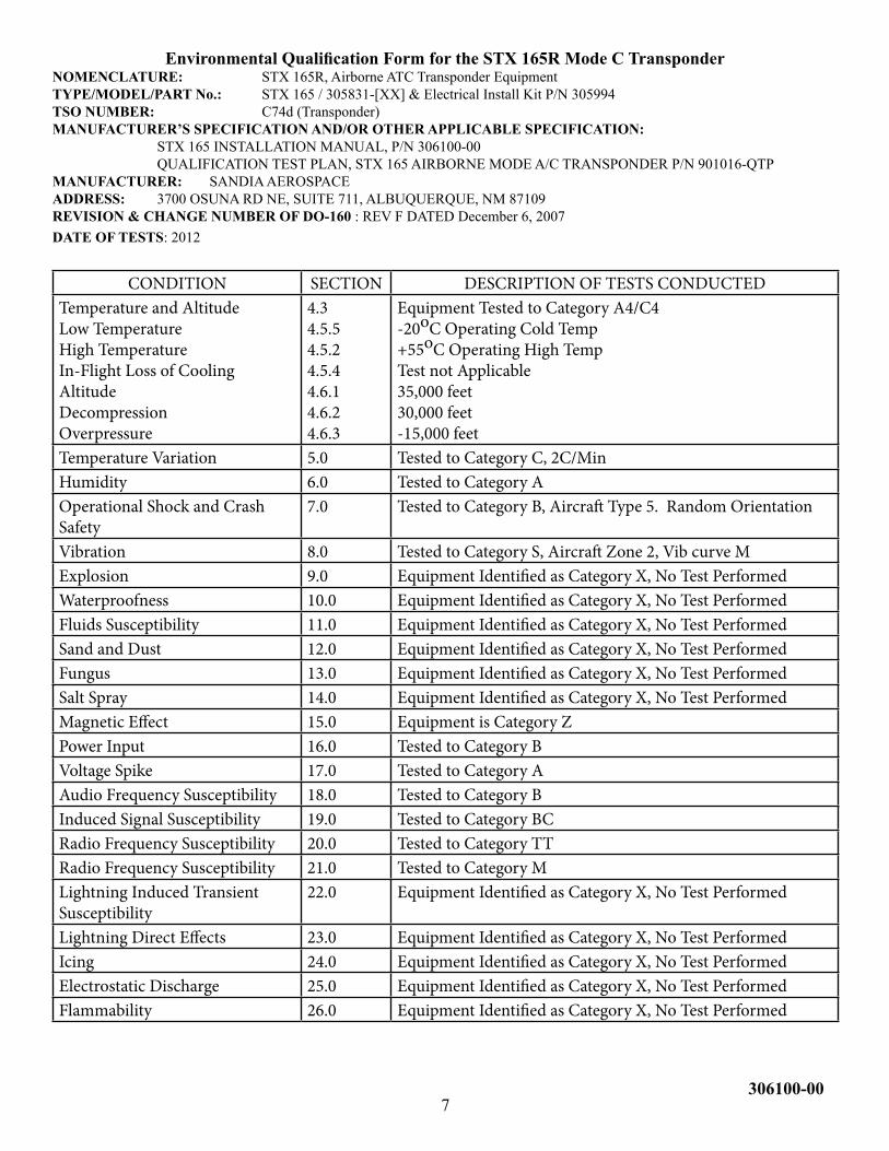
EnvironmentalQualificationFormfortheSTX165RModeCTransponderNOMENCLATURE: STX 165R, Airborne ATC Transponder EquipmentTYPE/MODEL/PART No.: STX 165 / 305831-[XX] & Electrical Install Kit P/N 305994TSO NUMBER: C74d (Transponder)MANUFACTURER’S SPECIFICATION AND/OR OTHER APPLICABLE SPECIFICATION: STX 165 INSTALLATION MANUAL, P/N 306100-00
QUALIFICATION TEST PLAN, STX 165 AIRBORNE MODE A/C TRANSPONDER P/N 901016-QTPMANUFACTURER: SANDIA AEROSPACEADDRESS: 3700 OSUNA RD NE, SUITE 711, ALBUQUERQUE, NM 87109REVISION & CHANGE NUMBER OF DO-160 : REV F DATED December 6, 2007DATE OF TESTS: 2012
CONDITION SECTION DESCRIPTION OF TESTS CONDUCTEDTemperature and AltitudeLow TemperatureHigh TemperatureIn-Flight Loss of CoolingAltitudeDecompressionOverpressure
4.34.5.54.5.24.5.44.6.14.6.24.6.3
Equipment Tested to Category A4/C4-20oC Operating Cold Temp+55oC Operating High TempTest not Applicable35,000 feet30,000 feet-15,000 feet
Temperature Variation 5.0 Tested to Category C, 2C/MinHumidity 6.0 Tested to Category AOperational Shock and Crash Safety
7.0 Tested to Category B, Aircraft Type 5. Random Orientation
Vibration 8.0 Tested to Category S, Aircraft Zone 2, Vib curve MExplosion 9.0 Equipment Identified as Category X, No Test PerformedWaterproofness 10.0 Equipment Identified as Category X, No Test PerformedFluids Susceptibility 11.0 Equipment Identified as Category X, No Test PerformedSand and Dust 12.0 Equipment Identified as Category X, No Test PerformedFungus 13.0 Equipment Identified as Category X, No Test PerformedSalt Spray 14.0 Equipment Identified as Category X, No Test PerformedMagnetic Effect 15.0 Equipment is Category ZPower Input 16.0 Tested to Category BVoltage Spike 17.0 Tested to Category AAudio Frequency Susceptibility 18.0 Tested to Category BInduced Signal Susceptibility 19.0 Tested to Category BCRadio Frequency Susceptibility 20.0 Tested to Category TTRadio Frequency Susceptibility 21.0 Tested to Category MLightning Induced Transient Susceptibility
22.0 Equipment Identified as Category X, No Test Performed
Lightning Direct Effects 23.0 Equipment Identified as Category X, No Test PerformedIcing 24.0 Equipment Identified as Category X, No Test PerformedElectrostatic Discharge 25.0 Equipment Identified as Category X, No Test PerformedFlammability 26.0 Equipment Identified as Category X, No Test Performed
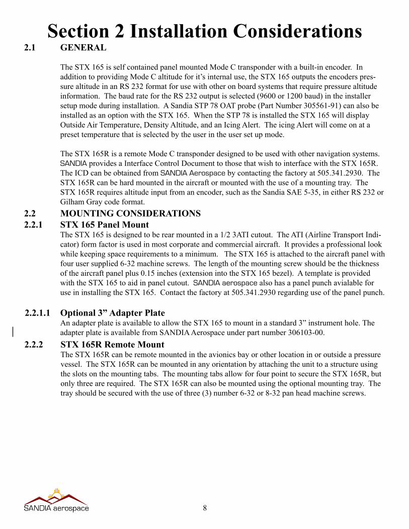
Section 2 Installation Considerations2.1 GENERAL
The STX 165 is self contained panel mounted Mode C transponder with a built-in encoder. In addition to providing Mode C altitude for it’s internal use, the STX 165 outputs the encoders pres-sure altitude in an RS 232 format for use with other on board systems that require pressure altitude information. The baud rate for the RS 232 output is selected (9600 or 1200 baud) in the installer setup mode during installation. A Sandia STP 78 OAT probe (Part Number 305561-91) can also be installed as an option with the STX 165. When the STP 78 is installed the STX 165 will display Outside Air Temperature, Density Altitude, and an Icing Alert. The icing Alert will come on at a preset temperature that is selected by the user in the user set up mode.
The STX 165R is a remote Mode C transponder designed to be used with other navigation systems. SANDIA provides a Interface Control Document to those that wish to interface with the STX 165R. The ICD can be obtained from SANDIA Aerospace by contacting the factory at 505.341.2930. The STX 165R can be hard mounted in the aircraft or mounted with the use of a mounting tray. The STX 165R requires altitude input from an encoder, such as the Sandia SAE 5-35, in either RS 232 or Gilham Gray code format.
2.2 MOUNTING CONSIDERATIONS2.2.1 STX 165 Panel Mount
The STX 165 is designed to be rear mounted in a 1/2 3ATI cutout. The ATI (Airline Transport Indi-cator)formfactorisusedinmostcorporateandcommercialaircraft.Itprovidesaprofessionallookwhilekeepingspacerequirementstoaminimum.TheSTX165isattachedtotheaircraftpanelwithfourusersupplied6-32machinescrews.Thelengthofthemountingscrewshouldbethethicknessof the aircraft panel plus 0.15 inches (extension into the STX 165 bezel). A template is provided with the STX 165 to aid in panel cutout. SANDIA aerospace also has a panel punch avialable for use in installing the STX 165. Contact the factory at 505.341.2930 regarding use of the panel punch.
2.2.1.1 Optional 3” Adapter PlateAn adapter plate is available to allow the STX 165 to mount in a standard 3” instrument hole. The adapter plate is available from SANDIA Aerospace under part number 306103-00.
2.2.2 STX 165R Remote MountThe STX 165R can be remote mounted in the avionics bay or other location in or outside a pressure vessel. The STX 165R can be mounted in any orientation by attaching the unit to a structure using the slots on the mounting tabs. The mounting tabs allow for four point to secure the STX 165R, but only three are required. The STX 165R can also be mounted using the optional mounting tray. The tray should be secured with the use of three (3) number 6-32 or 8-32 pan head machine screws.
8
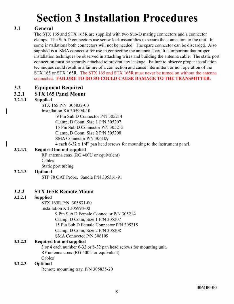
Section 3 Installation Procedures3.1 General
The STX 165 and STX 165R are supplied with two Sub-D mating connectors and a connector clamps.TheSub-Dconnectorsusescrewlockassembliestosecuretheconnectorstotheunit.Insome installations both connectors will not be needed. The spare connector can be discarded. Also supplied is a SMA connector for use in connecting the antenna coax. It is important that proper installation techniques be observed in attaching wires and building the antenna cable. The static port connectionmustbesecurelyattachedtopreventanyleakage.Failuretoobserveproperinstallationtechniques could result in a failure of a connection and cause intermittent or non operation of the STX 165 or STX 165R. The STX 165 and STX 165R must never be turned on without the antenna connected. FAILURE TO DO SO COULD CAUSE DAMAGE TO THE TRANSMITTER.
3.2.2 STX 165R Remote Mount3.2.2.1 Supplied STX 165R P/N 305831-00 Installation Kit 305994-00 9 Pin Sub D Female Connector P/N 305214 Clamp, D Conn, Size 1 P/N 305207 15 Pin Sub D Female Connector P/N 305215 Clamp, D Conn, Size 2 P/N 305208 SMA Connector P/N 3061093.2.2.2 Required but not supplied 3 or 4 each number 6-32 or 8-32 pan head screws for mounting unit. RF antenna coax (RG 400U or equivalent) Cables3.2.2.3 Optional Remote mounting tray, P/N 305835-20
3.2 Equipment Required 3.2.1 STX 165 Panel Mount3.2.1.1 Supplied STX 165 P/N 305832-00 Installation Kit 305994-10 9 Pin Sub D Connector P/N 305214 Clamp, D Conn, Size 1 P/N 305207 15 Pin Sub D Connector P/N 305215 Clamp, D Conn, Size 2 P/N 305208 SMA Connector P/N 306109 4 each 6-32 x 1/4” pan head screws for mounting to the instrument panel.3.2.1.2 Required but not supplied RF antenna coax (RG 400U or equivalent) Cables Static port tubing3.2.1.3 Optional STP 78 OAT Probe. Sandia P/N 305561-91
9306100-00
Installation to be in accordance with FAA AC 43.13-1B
WARNING: The STX 165 and STX 165R must NEVER be turned on without the antenna connected or a proper annunciator attached to the antenna output connector. Failure to do so will result in the failure of the transmitter output device. This type failure is not covered by the manufacturer’s warranty.
3.4 AIRCRAFT MOUNTING
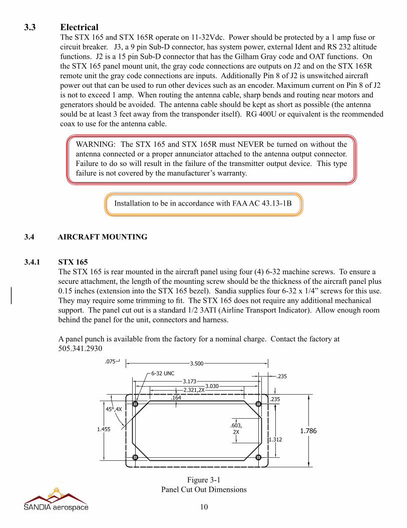
3.4.1 STX 165The STX 165 is rear mounted in the aircraft panel using four (4) 6-32 machine screws. To ensure a secureattachment,thelengthofthemountingscrewshouldbethethicknessoftheaircraftpanelplus0.15 inches (extension into the STX 165 bezel). Sandia supplies four 6-32 x 1/4” screws for this use. Theymayrequiresometrimmingtofit.TheSTX165doesnotrequireanyadditionalmechanicalsupport. The panel cut out is a standard 1/2 3ATI (Airline Transport Indicator). Allow enough room behind the panel for the unit, connectors and harness.
A panel punch is available from the factory for a nominal charge. Contact the factory at 505.341.2930
Figure 3-1Panel Cut Out Dimensions
3.3 ElectricalThe STX 165 and STX 165R operate on 11-32Vdc. Power should be protected by a 1 amp fuse or circuitbreaker.J3,a9pinSub-Dconnector,hassystempower,externalIdentandRS232altitudefunctions. J2 is a 15 pin Sub-D connector that has the Gilham Gray code and OAT functions. On the STX 165 panel mount unit, the gray code connections are outputs on J2 and on the STX 165R remote unit the gray code connections are inputs. Additionally Pin 8 of J2 is unswitched aircraft power out that can be used to run other devices such as an encoder. Maximum current on Pin 8 of J2 is not to exceed 1 amp. When routing the antenna cable, sharp bends and routing near motors and generatorsshouldbeavoided.Theantennacableshouldbekeptasshortaspossible(theantennasould be at least 3 feet away from the transponder itself). RG 400U or equivalent is the reommended coax to use for the antenna cable.
10
3.4.2 STX 165RTheSTX165Rremotetranspondercanbeeitherhardmountedusingthemountingflangesormount-ed in the optional mounting tray.
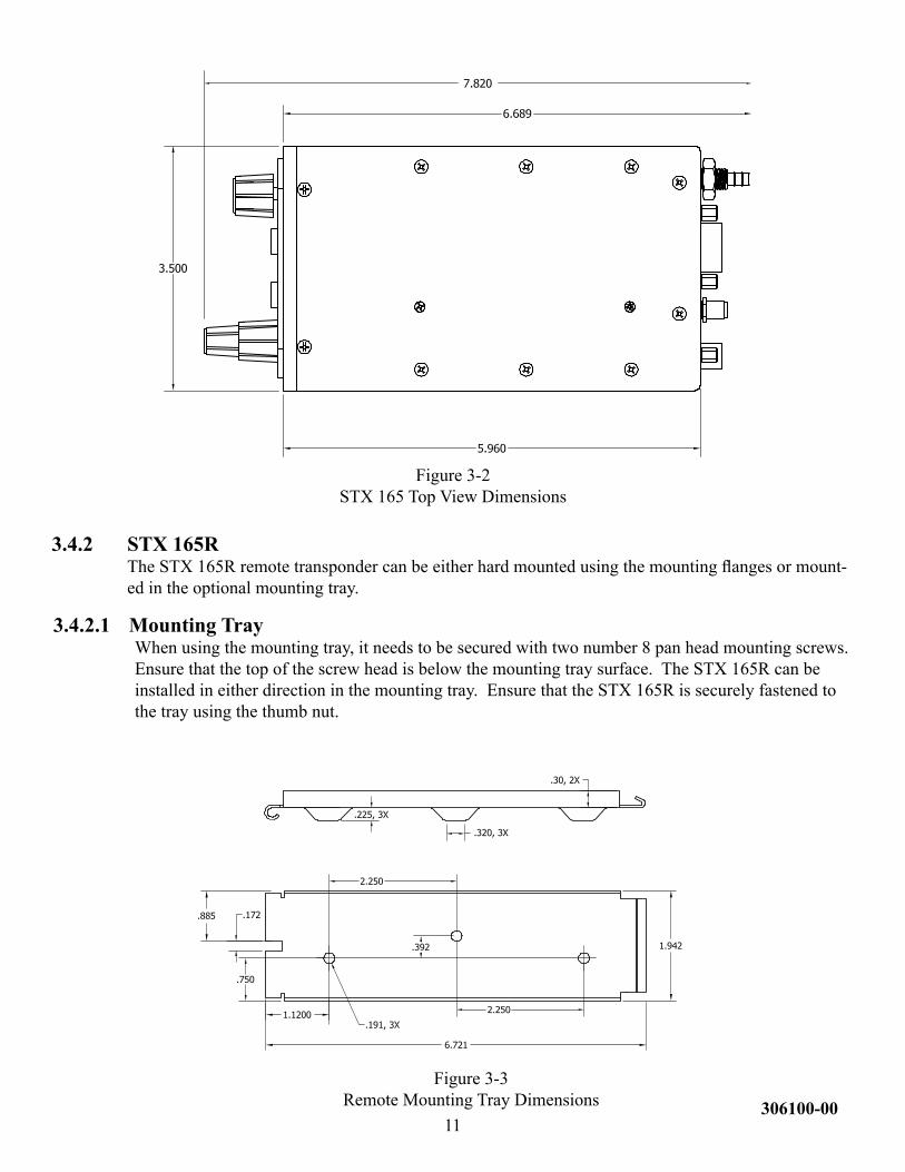
3.4.2.1 Mounting TrayWhen using the mounting tray, it needs to be secured with two number 8 pan head mounting screws. Ensure that the top of the screw head is below the mounting tray surface. The STX 165R can be installed in either direction in the mounting tray. Ensure that the STX 165R is securely fastened to the tray using the thumb nut.
Figure 3-3Remote Mounting Tray Dimensions
Figure 3-2STX 165 Top View Dimensions
11306100-00
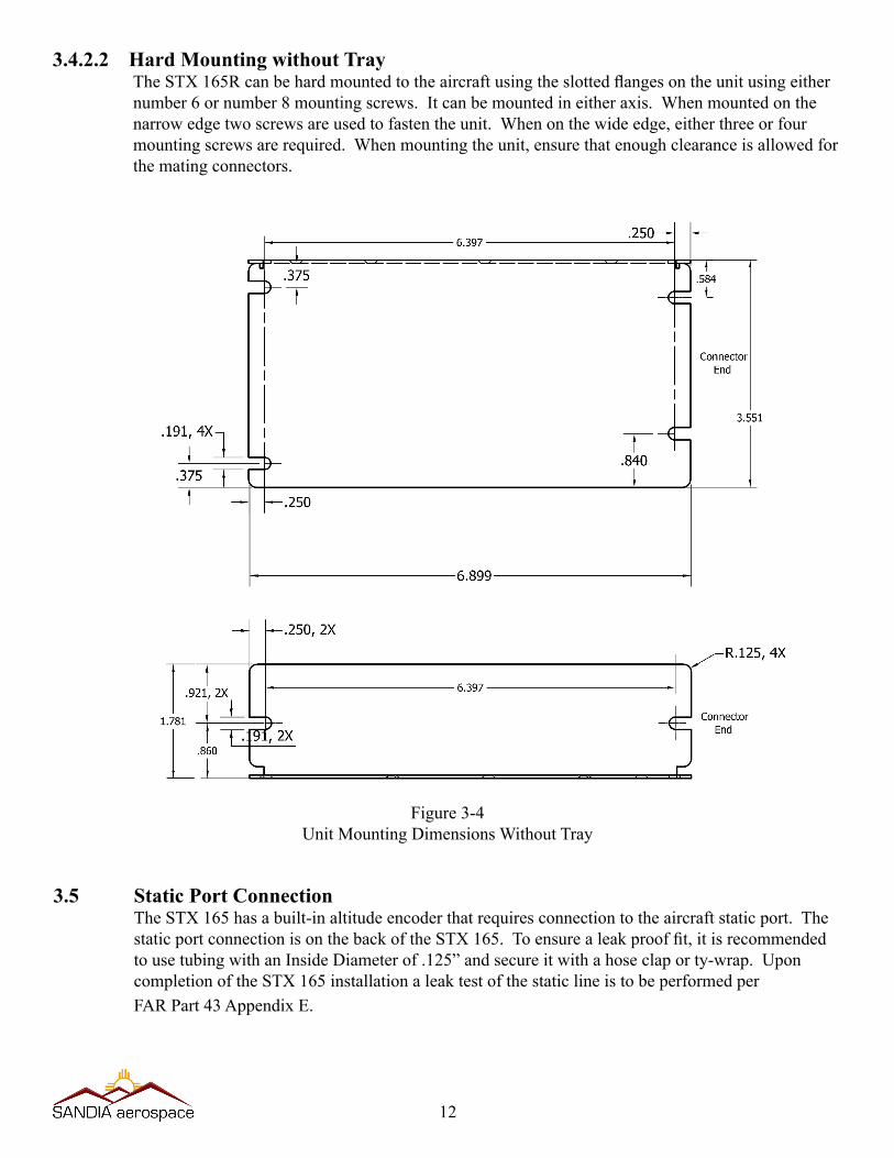
Figure 3-4Unit Mounting Dimensions Without Tray
3.4.2.2 Hard Mounting without TrayTheSTX165Rcanbehardmountedtotheaircraftusingtheslottedflangesontheunitusingeithernumber 6 or number 8 mounting screws. It can be mounted in either axis. When mounted on the narrow edge two screws are used to fasten the unit. When on the wide edge, either three or four mounting screws are required. When mounting the unit, ensure that enough clearance is allowed for the mating connectors.
12
3.5 Static Port ConnectionThe STX 165 has a built-in altitude encoder that requires connection to the aircraft static port. The staticportconnectionisonthebackoftheSTX165.Toensurealeakprooffit,itisrecommendedto use tubing with an Inside Diameter of .125” and secure it with a hose clap or ty-wrap. Upon completionoftheSTX165installationaleaktestofthestaticlineistobeperformedperFAR Part 43 Appendix E.
3.6 Electrical ConnectionThe STX 165 and STX 165R are designed to operate on 11-32Vdc without any special wiring con-siderations.Powershouldbesuppliedfromaircraftpowerthrougha1ampfuseorcircuitbreakertoprotect the transponder. The STX 165 and STX 165R also output unswitched aircraft power to oper-ateotheravionics.Ifthisoutputisused(aMaximumof1Amp),thefuseorbreakersizeshouldbeadjusted to accommodate the other system. Power and ground wires are 20 AWG. All other wires are 22 AWG unless otherwise noted.
3.6.1 STX 165 Panel Mounted UnitThe minimum installation for an operable STX 165 is Aircraft Power, Aircraft Ground, Antenna and Static Line. Aircraft power and ground are both found on J3, the 9 pin connector. The STX 165 outputs encoder altitude data in either RS 232 or Gilham Gray Code. The data format of the RS-232 altitude output corresponds with the baud rate selection. At 1200 baud, it outputs in extended altitude (#AL xxxxxT+15cc<CR>) format, and at 9600 baud it outputs in standard ICARUS format (ALT XXXX<CR>). The data formats are described in Appendix 1.
Forayokemountidentswitch,anexternalidentinputisprovided.GroundingtheExternalIdentlinewill activate the ident mode.
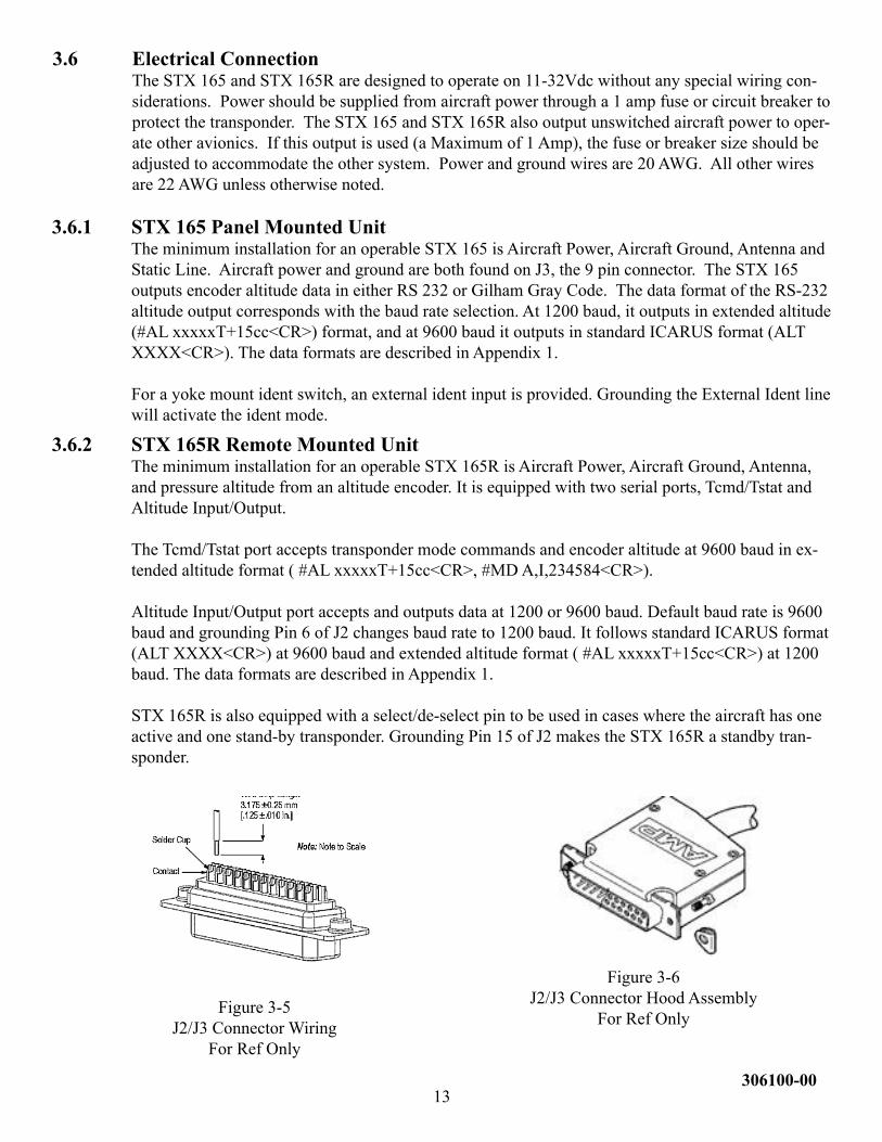
3.6.2 STX 165R Remote Mounted UnitThe minimum installation for an operable STX 165R is Aircraft Power, Aircraft Ground, Antenna, and pressure altitude from an altitude encoder. It is equipped with two serial ports, Tcmd/Tstat and Altitude Input/Output.
The Tcmd/Tstat port accepts transponder mode commands and encoder altitude at 9600 baud in ex-tended altitude format ( #AL xxxxxT+15cc<CR>, #MD A,I,234584<CR>).
Altitude Input/Output port accepts and outputs data at 1200 or 9600 baud. Default baud rate is 9600 baud and grounding Pin 6 of J2 changes baud rate to 1200 baud. It follows standard ICARUS format (ALT XXXX<CR>) at 9600 baud and extended altitude format ( #AL xxxxxT+15cc<CR>) at 1200 baud. The data formats are described in Appendix 1.
STX 165R is also equipped with a select/de-select pin to be used in cases where the aircraft has one activeandonestand-bytransponder.GroundingPin15ofJ2makestheSTX165Rastandbytran-sponder.
13306100-00
Figure 3-5J2/J3 Connector Wiring
For Ref Only
Figure 3-6J2/J3 Connector Hood Assembly
For Ref Only
14
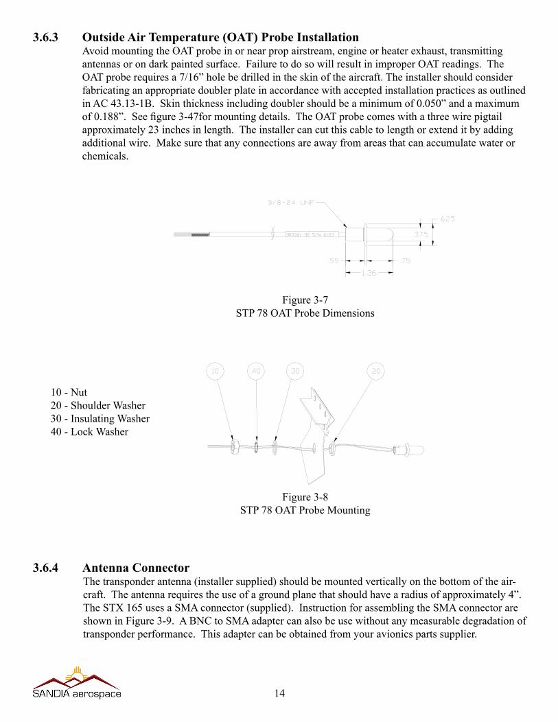
3.6.3 Outside Air Temperature (OAT) Probe InstallationAvoid mounting the OAT probe in or near prop airstream, engine or heater exhaust, transmitting antennasorondarkpaintedsurface.FailuretodosowillresultinimproperOATreadings.TheOATproberequiresa7/16”holebedrilledintheskinoftheaircraft.Theinstallershouldconsiderfabricating an appropriate doubler plate in accordance with accepted installation practices as outlined inAC43.13-1B.Skinthicknessincludingdoublershouldbeaminimumof0.050”andamaximumof0.188”.Seefigure3-47formountingdetails.TheOATprobecomeswithathreewirepigtailapproximately 23 inches in length. The installer can cut this cable to length or extend it by adding additionalwire.Makesurethatanyconnectionsareawayfromareasthatcanaccumulatewaterorchemicals.
10 - Nut20 - Shoulder Washer 30 - Insulating Washer40-LockWasher
Figure 3-7STP 78 OAT Probe Dimensions
Figure 3-8STP 78 OAT Probe Mounting
3.6.4 Antenna ConnectorThe transponder antenna (installer supplied) should be mounted vertically on the bottom of the air-craft. The antenna requires the use of a ground plane that should have a radius of approximately 4”. The STX 165 uses a SMA connector (supplied). Instruction for assembling the SMA connector are shown in Figure 3-9. A BNC to SMA adapter can also be use without any measurable degradation of transponder performance. This adapter can be obtained from your avionics parts supplier.
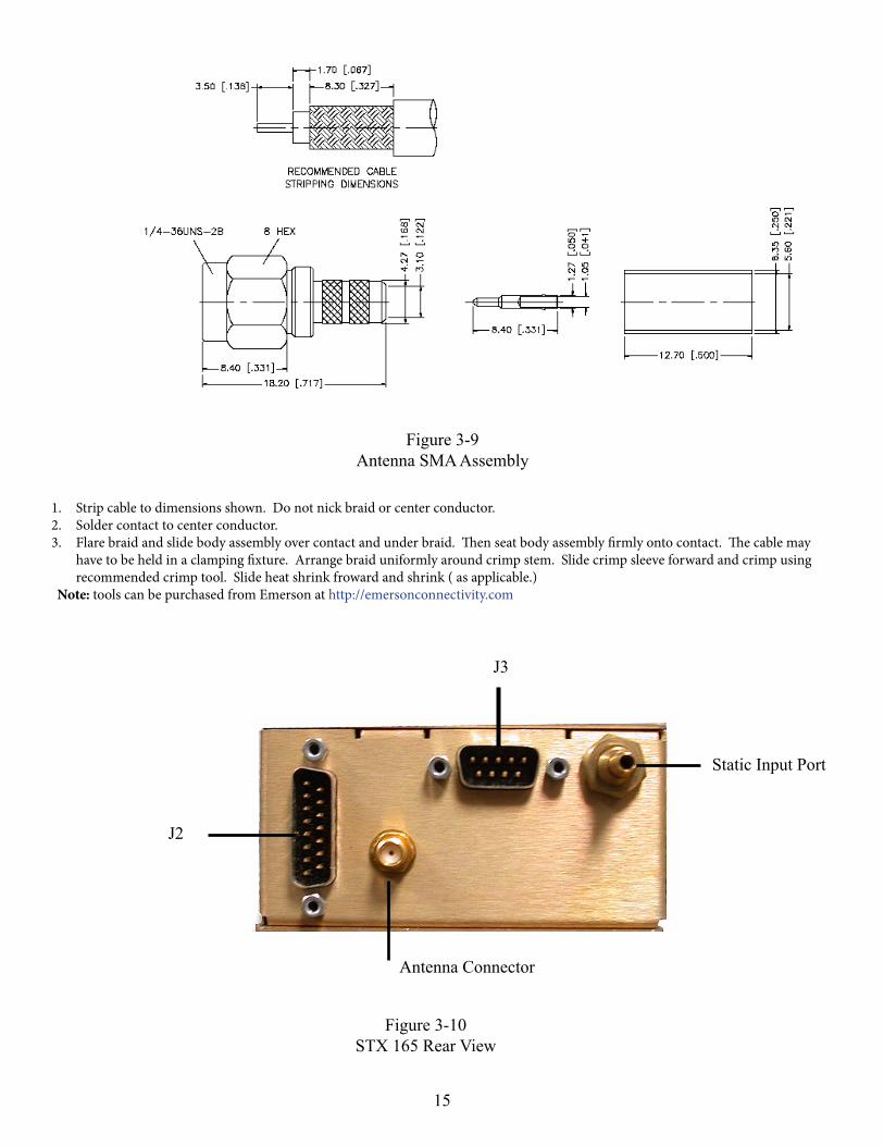
1. Strip cable to dimensions shown. Do not nick braid or center conductor. 2. Solder contact to center conductor.3. Flare braid and slide body assembly over contact and under braid. Then seat body assembly firmly onto contact. The cable may
have to be held in a clamping fixture. Arrange braid uniformly around crimp stem. Slide crimp sleeve forward and crimp using recommended crimp tool. Slide heat shrink froward and shrink ( as applicable.)
Note: tools can be purchased from Emerson at http://emersonconnectivity.com
J3
J2
Static Input Port
Antenna Connector
15
Figure 3-10STX 165 Rear View
Figure 3-9Antenna SMA Assembly
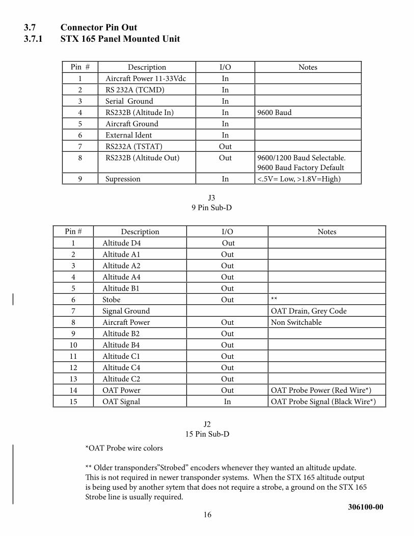
Pin # Description I/O Notes1 Aircraft Power 11-33Vdc In2 RS 232A (TCMD) In3 Serial Ground In4 RS232B (Altitude In) In 9600 Baud5 Aircraft Ground In6 External Ident In7 RS232A (TSTAT) Out8 RS232B (Altitude Out) Out 9600/1200 Baud Selectable.
9600 Baud Factory Default9 Supression In <.5V= Low, >1.8V=High)
Pin # Description I/O Notes1 Altitude D4 Out2 Altitude A1 Out3 Altitude A2 Out4 Altitude A4 Out5 Altitude B1 Out6 Stobe Out **7 Signal Ground OAT Drain, Grey Code8 Aircraft Power Out Non Switchable9 Altitude B2 Out
10 Altitude B4 Out11 Altitude C1 Out12 Altitude C4 Out13 Altitude C2 Out14 OAT Power Out OAT Probe Power (Red Wire*)15 OAT Signal In OAT Probe Signal (Black Wire*)
3.7 Connector Pin Out3.7.1 STX 165 Panel Mounted Unit
J39 Pin Sub-D
J215 Pin Sub-D
16306100-00
*OAT Probe wire colors
** Older transponders”Strobed” encoders whenever they wanted an altitude update. This is not required in newer transponder systems. When the STX 165 altitude output is being used by another sytem that does not require a strobe, a ground on the STX 165 Strobe line is usually required.
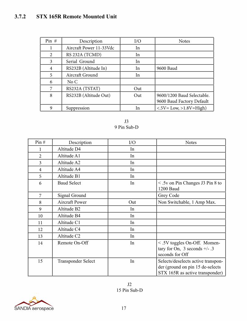
Pin # Description I/O Notes1 Aircraft Power 11-33Vdc In2 RS 232A (TCMD) In3 Serial Ground In4 RS232B (Altitude In) In 9600 Baud5 Aircraft Ground In6 No C7 RS232A (TSTAT) Out8 RS232B (Altitude Out) Out 9600/1200 Baud Selectable.
9600 Baud Factory Default9 Suppression In <.5V= Low, >1.8V=High)
Pin # Description I/O Notes1 Altitude D4 In2 Altitude A1 In3 Altitude A2 In4 Altitude A4 In5 Altitude B1 In6 Baud Select In < .5v on Pin Changes J3 Pin 8 to
1200 Baud7 Signal Ground Grey Code8 Aircraft Power Out Non Switchable, 1 Amp Max.9 Altitude B2 In
10 Altitude B4 In11 Altitude C1 In12 Altitude C4 In13 Altitude C2 In14 Remote On-Off In < .5V toggles On-Off. Momen-
tary for On, 3 seconds +/- .3 seconds for Off
15 Transponder Select In Selects/deselects active transpon-der (ground on pin 15 de-selects STX 165R as active transponder)
J39 Pin Sub-D
J215 Pin Sub-D
3.7.2 STX 165R Remote Mounted Unit
17
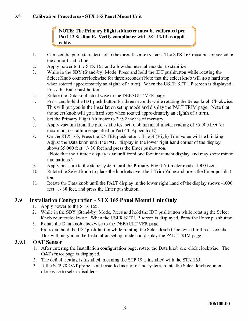
3.8 Calibration Procedures - STX 165 Panel Mount Unit
NOTE: The Primary Flight Altimeter must be calibrated per Part 43 Section E. Verify compliance with AC-43.13 as appli-cable.
1. Connect the pitot-static test set to the aircraft static system. The STX 165 must be connected to the aircraft static line.
2. Apply power to the STX 165 and allow the internal encoder to stabilize.3. While in the SBY (Stand-by) Mode, Press and hold the IDT pushbutton while rotating the
SelectKnobcounterclockwiseforthreeseconds(Notethattheselectknobwillgoahardstopwhen rotated approximately an eighth of a turn). When the USER SET UP screen is displayed, Press the Enter pushbutton.
4. RotatetheDataknobclockwisetotheDEFAULTVFRpage.5. PressandholdtheIDTpush-buttonforthreesecondswhilerotatingtheSelectknobClockwise.
This will put you in the Installation set up mode and display the PALT TRIM page. (Note that theselectknobwillgoahardstopwhenrotatedapproximatelyaneighthofaturn).
6. Set the Primary Flight Altimeter to 29.92 inches of mercury.7. Apply vacuum from the pitot-static test set to obtain an altimeter reading of 35,000 feet (or
maximumtestaltitudespecifiedinPart43,AppendixE).8. OntheSTX165,PresstheENTERpushbutton.TheH(High)Trimvaluewillbeblinking.
AdjusttheDataknobuntilthePALTdisplayinthelowerrighthandcornerofthedisplayshows 35,000 feet +/- 30 feet and press the Enter pushbutton.
(Notethatthealtitudedisplayisanunfilteredonefootincrementdisplay,andmayshowminorfluctuations.)
9. Apply pressure to the static system until the Primary Flight Altimeter reads -1000 feet.10. RotatetheSelectknobtoplacethebracketsovertheLTrimValueandpresstheEnterpushbut-
ton.11. RotatetheDataknobuntilthePALTdisplayinthelowerrighthandofthedisplayshows-1000
feet +/- 30 feet, and press the Enter pushbutton.
3.9 InstallationConfiguration-STX165PanelMountUnitOnly1. Apply power to the STX 165.2. While in the SBY (Stand-by) Mode, Press and hold the IDT pushbutton while rotating the Select
Knobcounterclockwise.WhentheUSERSETUPscreenisdisplayed,PresstheEnterpushbutton.3. RotatetheDataknobclockwisetotheDEFAULTVFRpage.4. PressandholdtheIDTpush-buttonwhilerotatingtheSelectknobClockwiseforthreeseconds.
This will put you in the Installation set up mode and display the PALT TRIM page.3.9.1 OAT Sensor
1. AfterenteringtheInstallationconfigurationpage,rotatetheDataknoboneclickclockwise.TheOAT sensor page is displayed.
2. The default setting is Installed, meaning the STP 78 is installed with the STX 165. 3. IftheSTP78OATprobeisnotinstalledaspartofthesystem,rotatetheSelectknobcounter-
clockwisetoselectdisabled.
18306100-00
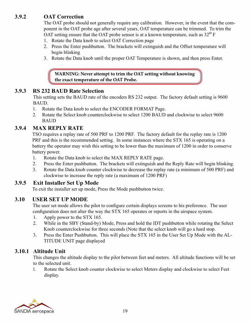
3.9.2 OAT CorrectionThe OAT probe should not generally require any calibration. However, in the event that the com-ponent in the OAT probe age after several years, OAT temperature can be trimmed. To trim the OATsettingensurethattheOATprobesensorisataknowntemperature,suchas32o F1. RotatetheDataknobtoselectOATCorrectionpage2. PresstheEnterpushbutton.ThebracketswillextinguishandtheOffsettemperaturewill
beginblinking3. RotatetheDataknobuntiltheproperOATTemperatureisshown,andthenpressEnter.
WARNING: Never attempt to trim the OAT setting without knowing the exact temperature of the OAT Probe.
3.9.3 RS 232 BAUD Rate SelectionThis setting sets the BAUD rate of the encoders RS 232 output. The factory default setting is 9600 BAUD.1. RotatetheDataknobtoselecttheENCODERFORMATPage.2. RotatetheSelectknobcounterclockwisetoselect1200BAUDandclockwisetoselect9600
BAUD3.9.4 MAX REPLY RATE
TSO requires a replay rate of 500 PRF to 1200 PRF. The factory default for the replay rate is 1200 PRF and this is the recommended setting. In some instances where the STX 165 is operating on a battery the operator may wish this setting to be lower than the maximum of 1200 in order to conserve battery power.1. RotatetheDataknobtoselecttheMAXREPLYRATEpage.2. PresstheEnterpushbutton.ThebracketswillextinguishandtheReplyRatewillbeginblinking.3. RotatetheDataknobcounterclockwisetodecreasethereplayrate(aminimumof500PRF)and
clockwisetoincreasethereplyrate(amaximumof1200PRF)3.9.5 Exit Installer Set Up Mode
To exit the installer set up mode, Press the Mode pushbutton twice.
3.10 USER SET UP MODETheusersetmodeallowsthepilottoconfigurecertaindisplaysscreenstohispreference.TheuserconfigurationdoesnotalterthewaytheSTX165operatesorreportsintheairspacesystem.1. Apply power to the STX 165. 2. While in the SBY (Stand-by) Mode, Press and hold the IDT pushbutton while rotating the Select
Knobcounterclockwiseforthreeseconds(Notethattheselectknobwillgoahardstop.3. Press the Enter Pushbutton. This will place the STX 165 in the User Set Up Mode with the AL-
TITUDE UNIT page displayed
3.10.1 Altitude UnitThis changes the altitude display to the pilot between feet and meters. All altitude functions will be set to the selected unit.1. RotatetheSelectknobcounterclockwisetoselectMetersdisplayandclockwisetoselectFeet
display.
19
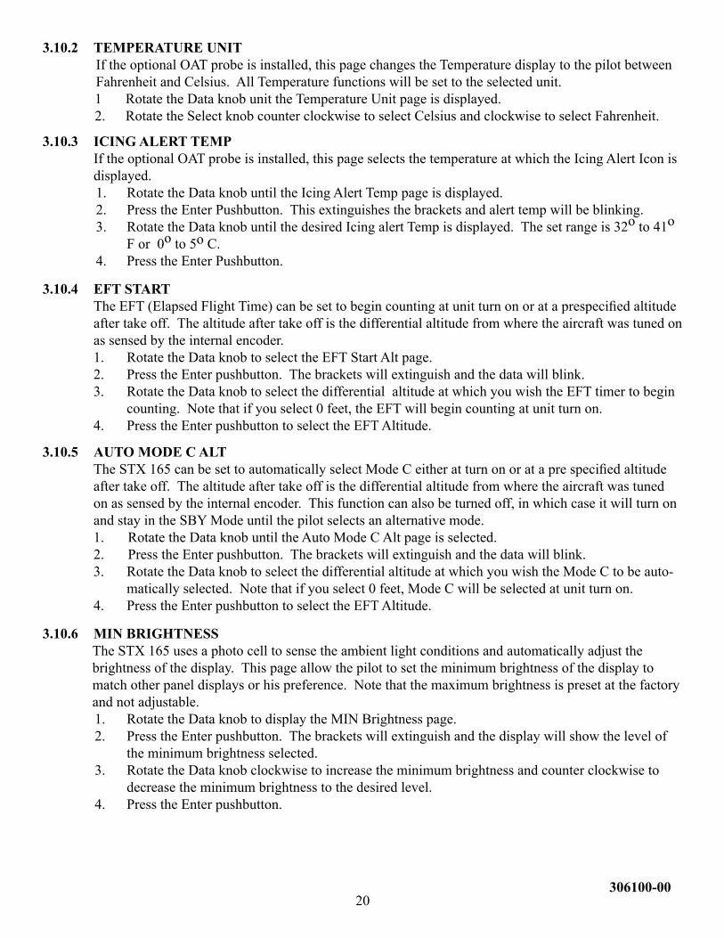
3.10.2 TEMPERATURE UNITIf the optional OAT probe is installed, this page changes the Temperature display to the pilot between Fahrenheit and Celsius. All Temperature functions will be set to the selected unit.1 RotatetheDataknobunittheTemperatureUnitpageisdisplayed.2. RotatetheSelectknobcounterclockwisetoselectCelsiusandclockwisetoselectFahrenheit.
3.10.3 ICING ALERT TEMPIf the optional OAT probe is installed, this page selects the temperature at which the Icing Alert Icon is displayed.1. RotatetheDataknobuntiltheIcingAlertTemppageisdisplayed.2. PresstheEnterPushbutton.Thisextinguishesthebracketsandalerttempwillbeblinking.3. RotatetheDataknobuntilthedesiredIcingalertTempisdisplayed.Thesetrangeis32o to 41o
F or 0o to 5o C.4. Press the Enter Pushbutton.
3.10.4 EFT STARTTheEFT(ElapsedFlightTime)canbesettobegincountingatunitturnonorataprespecifiedaltitudeaftertakeoff.Thealtitudeaftertakeoffisthedifferentialaltitudefromwheretheaircraftwastunedonas sensed by the internal encoder. 1. RotatetheDataknobtoselecttheEFTStartAltpage.2. PresstheEnterpushbutton.Thebracketswillextinguishandthedatawillblink.3. RotatetheDataknobtoselectthedifferentialaltitudeatwhichyouwishtheEFTtimertobegin
counting. Note that if you select 0 feet, the EFT will begin counting at unit turn on.4. Press the Enter pushbutton to select the EFT Altitude.
3.10.5 AUTO MODE C ALTTheSTX165canbesettoautomaticallyselectModeCeitheratturnonorataprespecifiedaltitudeaftertakeoff.Thealtitudeaftertakeoffisthedifferentialaltitudefromwheretheaircraftwastunedon as sensed by the internal encoder. This function can also be turned off, in which case it will turn on and stay in the SBY Mode until the pilot selects an alternative mode.1. RotatetheDataknobuntiltheAutoModeCAltpageisselected.2. PresstheEnterpushbutton.Thebracketswillextinguishandthedatawillblink.3. RotatetheDataknobtoselectthedifferentialaltitudeatwhichyouwishtheModeCtobeauto-
matically selected. Note that if you select 0 feet, Mode C will be selected at unit turn on.4. Press the Enter pushbutton to select the EFT Altitude.
3.10.6 MIN BRIGHTNESSThe STX 165 uses a photo cell to sense the ambient light conditions and automatically adjust the brightness of the display. This page allow the pilot to set the minimum brightness of the display to match other panel displays or his preference. Note that the maximum brightness is preset at the factory and not adjustable.1. RotatetheDataknobtodisplaytheMINBrightnesspage.2. PresstheEnterpushbutton.Thebracketswillextinguishandthedisplaywillshowthelevelof
the minimum brightness selected.3. RotatetheDataknobclockwisetoincreasetheminimumbrightnessandcounterclockwiseto
decrease the minimum brightness to the desired level.4. Press the Enter pushbutton.
20306100-00
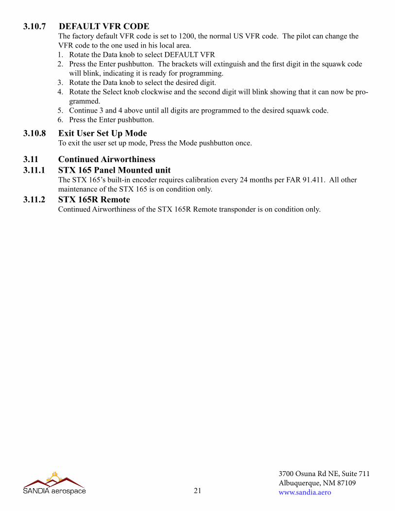
3.11 Continued Airworthiness 3.11.1 STX 165 Panel Mounted unit
The STX 165’s built-in encoder requires calibration every 24 months per FAR 91.411. All other maintenance of the STX 165 is on condition only.
3.11.2 STX 165R Remote Continued Airworthiness of the STX 165R Remote transponder is on condition only.
3.10.7 DEFAULT VFR CODEThe factory default VFR code is set to 1200, the normal US VFR code. The pilot can change the VFR code to the one used in his local area.1. RotatetheDataknobtoselectDEFAULTVFR2. PresstheEnterpushbutton.Thebracketswillextinguishandthefirstdigitinthesquawkcode
willblink,indicatingitisreadyforprogramming.3. RotatetheDataknobtoselectthedesireddigit.4. RotatetheSelectknobclockwiseandtheseconddigitwillblinkshowingthatitcannowbepro-
grammed.5. Continue3and4aboveuntilalldigitsareprogrammedtothedesiredsquawkcode.6. Press the Enter pushbutton.
3.10.8 Exit User Set Up ModeTo exit the user set up mode, Press the Mode pushbutton once.
21
3700 Osuna Rd NE, Suite 711Albuquerque, NM 87109www.sandia.aero