Embed Size (px)
Citation preview
123302
STYLE 6000 SERIES CAN MESSAGING REFERENCE MANUALOPERATING INSTRUCTIONS
CAN MESSAGING
Prerequisite KnowledgeIt is assumed that the reader has some level of familiarity with CAN networking and terminology, and the Akron Brass product. This information is not intended to be a tutorial on CAN, nor Akron Brass product operation, but rather a resource for information concerning the requirements and techniques involved in implementing a CAN control interface to the Akron Brass product line.
CAN Physical LayerAkron Brass CAN physical layer requirements are generally as specified in SAE J1939-11 Physical Layer | SAE J1939-15 Reduced Physical Layer: •CAN2.0Bdevices •29bitCANmessageheaders •250Kbitspersecond •Properbuswiring,terminations,etc.
Address ClaimingRather than using a pre-assigned CAN node address, Akron Brass controllers and display devices by default use the J1939 method of address claiming, detailed in SAE J1939-81 Network Management. Although the integrator must be aware of this, it is not necessary for them to understand or use this technique. Integrator considerations regarding this are summarized in Appendix A.
General Message CharacteristicsTo allow Akron Brass devices to cooperatively communicate on a vehicle bus shared with other message traffic, all Akron Brass messages utilize the point-to-point and broadcast ranges of message IDs set aside in SAE J1939-71 Vehicle Application Layer for vendors to use to transmit data not other-wise defined in the J1939 specification. The messages are structured as follows:
Header 2 2 2 1 1 0 0 0 Bit 9...5 4......7 6......9 8......1 [.]|| [......] [......] [......] [.]|| [......] [......] ↑ 8 bits, Source node [.]|| [......] ↑ 8 bits, PDU specific, Destination node ( FF
hex if Broadcast )
[.]|| ↑ 8 bits, PDU format, 11101111 = EFhex = 239 = PGN EF00
hex = 61184
[.]|↑ 1 bit, Data Page, 0 [.]↑ 1 bit, Extended Data Page, 0 ↑ 3 bits, Priority, 111 = 7 = lowest, 000 = 0 = highest
Data length - 1 to 8 bytes
Data byte 1 = Message typeDatabytes2-8=Dataformessagetype(0to7bytes)
PriorityfieldisusedonlyforphysicalCANbusarbitration.Allmessagesareparsedbasedontheloworder26bitsoftheheader.
No logical messages are spanned across multiple physical CAN messages.
Page02
Input Messages
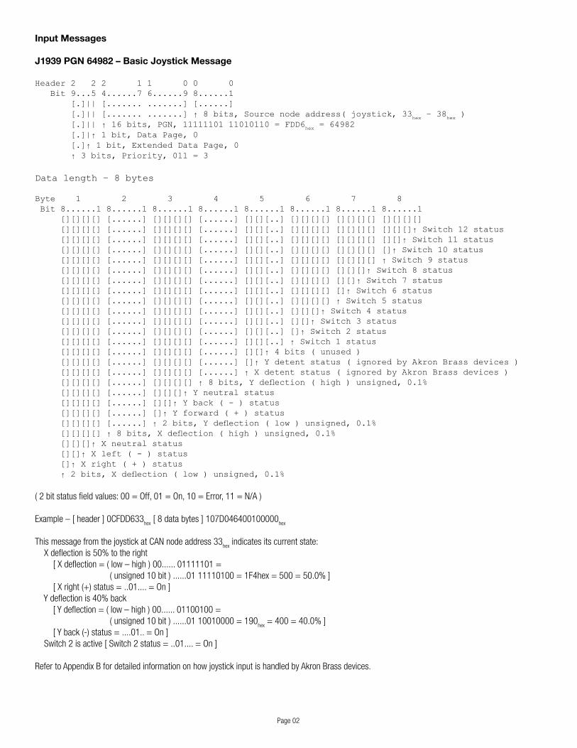
J1939 PGN 64982 – Basic Joystick Message
Header 2 2 2 1 1 0 0 0 Bit 9...5 4......7 6......9 8......1 [.]|| [....... .......] [......] [.]|| [....... .......] ↑ 8 bits, Source node address( joystick, 33
hex – 38
hex )
[.]|| ↑ 16 bits, PGN, 11111101 11010110 = FDD6hex = 64982
[.]|↑ 1 bit, Data Page, 0 [.]↑ 1 bit, Extended Data Page, 0 ↑ 3 bits, Priority, 011 = 3
Data length – 8 bytes
Byte 1 2 3 4 5 6 7 8 Bit 8......1 8......1 8......1 8......1 8......1 8......1 8......1 8......1 [][][][] [......] [][][][] [......] [][][..] [][][][] [][][][] [][][][] [][][][] [......] [][][][] [......] [][][..] [][][][] [][][][] [][][]↑ Switch 12 status [][][][] [......] [][][][] [......] [][][..] [][][][] [][][][] [][]↑ Switch 11 status [][][][] [......] [][][][] [......] [][][..] [][][][] [][][][] []↑ Switch 10 status [][][][] [......] [][][][] [......] [][][..] [][][][] [][][][] ↑ Switch 9 status [][][][] [......] [][][][] [......] [][][..] [][][][] [][][]↑ Switch 8 status [][][][] [......] [][][][] [......] [][][..] [][][][] [][]↑ Switch 7 status [][][][] [......] [][][][] [......] [][][..] [][][][] []↑ Switch 6 status [][][][] [......] [][][][] [......] [][][..] [][][][] ↑ Switch 5 status [][][][] [......] [][][][] [......] [][][..] [][][]↑ Switch 4 status [][][][] [......] [][][][] [......] [][][..] [][]↑ Switch 3 status [][][][] [......] [][][][] [......] [][][..] []↑ Switch 2 status [][][][] [......] [][][][] [......] [][][..] ↑ Switch 1 status [][][][] [......] [][][][] [......] [][]↑ 4 bits ( unused ) [][][][] [......] [][][][] [......] []↑ Y detent status ( ignored by Akron Brass devices ) [][][][] [......] [][][][] [......] ↑ X detent status ( ignored by Akron Brass devices ) [][][][] [......] [][][][] ↑ 8 bits, Y deflection ( high ) unsigned, 0.1% [][][][] [......] [][][]↑ Y neutral status [][][][] [......] [][]↑ Y back ( - ) status [][][][] [......] []↑ Y forward ( + ) status [][][][] [......] ↑ 2 bits, Y deflection ( low ) unsigned, 0.1% [][][][] ↑ 8 bits, X deflection ( high ) unsigned, 0.1% [][][]↑ X neutral status [][]↑ X left ( - ) status []↑ X right ( + ) status ↑ 2 bits, X deflection ( low ) unsigned, 0.1%
(2bitstatusfieldvalues:00=Off,01=On,10=Error,11=N/A)
Example–[header]0CFDD633hex[8databytes]107D046400100000
hex
This message from the joystick at CAN node address 33hex
indicates its current state:Xdeflectionis50%totheright[Xdeflection=(low–high)00......01111101=(unsigned10bit)......0111110100=1F4hex=500=50.0%][Xright(+)status=..01....=On]Ydeflectionis40%back[Ydeflection=(low–high)00......01100100=(unsigned10bit)......0110010000=190
hex=400=40.0%]
[Yback(-)status=....01..=On]Switch2isactive[Switch2status=..01....=On]
Refer to Appendix B for detailed information on how joystick input is handled by Akron Brass devices.
Page 03
Input Messages (continued)
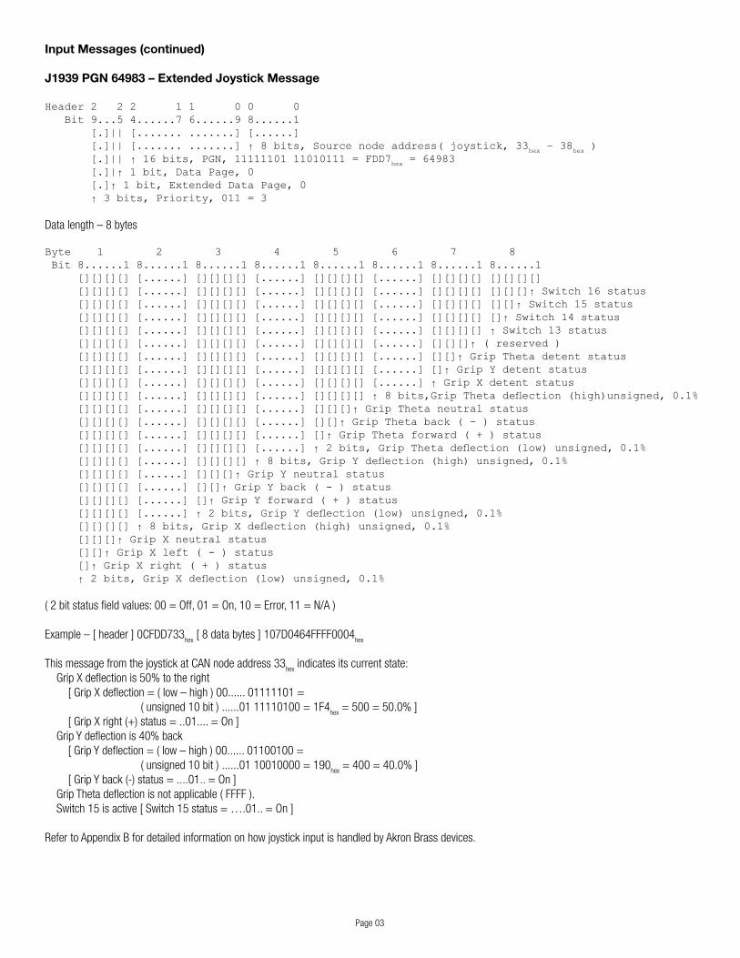
J1939 PGN 64983 – Extended Joystick Message
Header 2 2 2 1 1 0 0 0 Bit 9...5 4......7 6......9 8......1 [.]|| [....... .......] [......] [.]|| [....... .......] ↑ 8 bits, Source node address( joystick, 33
hex – 38
hex )
[.]|| ↑ 16 bits, PGN, 11111101 11010111 = FDD7hex = 64983
[.]|↑ 1 bit, Data Page, 0 [.]↑ 1 bit, Extended Data Page, 0 ↑ 3 bits, Priority, 011 = 3
Data length – 8 bytes
Byte 1 2 3 4 5 6 7 8 Bit 8......1 8......1 8......1 8......1 8......1 8......1 8......1 8......1 [][][][] [......] [][][][] [......] [][][][] [......] [][][][] [][][][] [][][][] [......] [][][][] [......] [][][][] [......] [][][][] [][][]↑ Switch 16 status [][][][] [......] [][][][] [......] [][][][] [......] [][][][] [][]↑ Switch 15 status [][][][] [......] [][][][] [......] [][][][] [......] [][][][] []↑ Switch 14 status [][][][] [......] [][][][] [......] [][][][] [......] [][][][] ↑ Switch 13 status [][][][] [......] [][][][] [......] [][][][] [......] [][][]↑ ( reserved ) [][][][] [......] [][][][] [......] [][][][] [......] [][]↑ Grip Theta detent status [][][][] [......] [][][][] [......] [][][][] [......] []↑ Grip Y detent status [][][][] [......] [][][][] [......] [][][][] [......] ↑ Grip X detent status [][][][] [......] [][][][] [......] [][][][] ↑ 8 bits,Grip Theta deflection (high)unsigned, 0.1% [][][][] [......] [][][][] [......] [][][]↑ Grip Theta neutral status [][][][] [......] [][][][] [......] [][]↑ Grip Theta back ( - ) status [][][][] [......] [][][][] [......] []↑ Grip Theta forward ( + ) status [][][][] [......] [][][][] [......] ↑ 2 bits, Grip Theta deflection (low) unsigned, 0.1% [][][][] [......] [][][][] ↑ 8 bits, Grip Y deflection (high) unsigned, 0.1% [][][][] [......] [][][]↑ Grip Y neutral status [][][][] [......] [][]↑ Grip Y back ( - ) status [][][][] [......] []↑ Grip Y forward ( + ) status [][][][] [......] ↑ 2 bits, Grip Y deflection (low) unsigned, 0.1% [][][][] ↑ 8 bits, Grip X deflection (high) unsigned, 0.1% [][][]↑ Grip X neutral status [][]↑ Grip X left ( - ) status []↑ Grip X right ( + ) status ↑ 2 bits, Grip X deflection (low) unsigned, 0.1%
(2bitstatusfieldvalues:00=Off,01=On,10=Error,11=N/A)
Example–[header]0CFDD733hex[8databytes]107D0464FFFF0004
hex
This message from the joystick at CAN node address 33hex
indicates its current state:GripXdeflectionis50%totheright[GripXdeflection=(low–high)00......01111101=(unsigned10bit)......0111110100=1F4
hex=500=50.0%]
[GripXright(+)status=..01....=On]GripYdeflectionis40%back[GripYdeflection=(low–high)00......01100100=(unsigned10bit)......0110010000=190
hex=400=40.0%]
[GripYback(-)status=....01..=On]GripThetadeflectionisnotapplicable(FFFF).Switch15isactive[Switch15status=….01..=On]
Refer to Appendix B for detailed information on how joystick input is handled by Akron Brass devices.
Page04
Status Messages – Broadcast
Message type FFhex – Address Announcement
This message is issued to inform the integrator what CAN node address has been claimed for use by the Akron Brass devicehavingtheindicatedPIN(15digitProductIdentificationNumber,similartoEthernetMacIDinthatituniquely identifiesanyAkronBrassdevice).
HeaderperGeneralMessageCharacteristics,Destinationnode=FFhex(Broadcast)
Data length – 8 bytes
Byte 1 2 3 4 5 6 7 8 Bit 8......1 8......1 8......1 8......1 8......1 8......1 8......1 8......1 [......] [.....][ .....][. ........ .][..... ........ ........ .......] [......] [.....][ .....][. ........ .]↑ 30 bits ( high - low ) unsigned, PIN digits 7-15 [......] [.....][ .....]↑ 12 bits ( high - low ) unsigned, PIN digits 1-4 [......] [.....]↑ 7 bits, PIN digit 6 ( ASCII character ) [......] ↑ 7 bits, PIN digit 5 ( ASCII character ) ↑ 8 bits, message type, 11111111 = FF
hex
Example–[header]18EFFF80hex[8databytes]FF83150226021A0Bhex
Thismessageindicatesthatthe6032UniversalIIdevicewithPIN‘1032AE100801035’hasclaimedCANnodeaddress80hex
and is ready to issue and accept CAN messages.[PINdigits1-4=(high–low)......010000001000......=(unsigned12bit)....010000001000=408
hex=1032]
[PINdigit5=1000001.=(7bitASCII).1000001=41hex=‘A’]
[PINdigit6=.......1000101..=(7bitASCII).1000101=45hex=‘E’]
[PINdigits7-15=(high–low)..100110000000100001101000001011=(unsigned30bit)..100110000000100001101000001011=26021A0B
hex=100801035]
Refer to Appendix A for more detailed information regarding how this message should be processed.
Message type FDhex – Diagnostic Data ( Akron Brass internal / diagnostic use )
These messages are issued when a device is placed into Diagnostic mode, and are processed by the Akroview diagnostic program. The format and content are specific to an individual device type.
HeaderperGeneralMessageCharacteristics,Destinationnode=FFhex(Broadcast)
Data length – 3 to 8 bytes
Byte 1 2 3 4 5 6 7 8 Bit 8......1 8......1 8......1 8......1 8......1 8......1 8......1 8......1 [......] [......] [ ...... ........ ........ ........ ........ .......] [......] [......] ↑ Format and content vary by device [......] ↑ 8 bits, Diagnostic record type ↑ 8 bits, message type, 11111101 = FD
hex
Example–[header]18EFFF80hex[5databytes]FD01000000
hex
Formatandcontentvarybydevice.

Page05
Status Messages – Broadcast (continued)
Message type 01hex – Position / Limit Status
Thismessageisissuedperiodically(100ms)bythe6032UniversalII,6040Forestryand6042GlobalPlatformcontrollerstoindicateaxispositions(forunitswithanalogfeedback),travellimitstatus,et.al.
HeaderperGeneralMessageCharacteristics,Destinationnode=FFhex(Broadcast)
Data length – 8 bytes
Byte 1 2 3 4 5 6 7 8 Bit 8......1 8......1 8......1 8......1 8......1 8......1 8......1 8......1 [......] [....... ...][][] [....... ...][][] [][][][] [][][][] [][][][] [......] [....... ...][][] [....... ...][][] [][][][] [][][][] [][][]↑ Calibration status [......] [....... ...][][] [....... ...][][] [][][][] [][][][] [][]↑ 2 bits ( unused ) [......] [....... ...][][] [....... ...][][] [][][][] [][][][] []↑ Axis 5(-) hard stop status [......] [....... ...][][] [....... ...][][] [][][][] [][][][] ↑ Axis 5(+) hard stop status [......] [....... ...][][] [....... ...][][] [][][][] [][][]↑ Axis 4(-) hard stop status [......] [....... ...][][] [....... ...][][] [][][][] [][]↑ Axis 4(+) hard stop status [......] [....... ...][][] [....... ...][][] [][][][] []↑ Axis 3(-) hard stop status [......] [....... ...][][] [....... ...][][] [][][][] ↑ Axis 3(+) hard stop status [......] [....... ...][][] [....... ...][][] [][][]↑ Axis 2(-) hard stop status [......] [....... ...][][] [....... ...][][] [][]↑ Axis 2(+) hard stop status [......] [....... ...][][] [....... ...][][] []↑ Axis 1(-) hard stop status [......] [....... ...][][] [....... ...][][] ↑ Axis 1(+) hard stop status [......] [....... ...][][] [....... ...][]↑ Elevation Down(-) position status [......] [....... ...][][] [....... ...]↑ Elevation Up(+) position status [......] [....... ...][][] ↑ 12 bits ( high - low ) unsigned, Elevation position, 0.1° [......] [....... ...][]↑ Rotation Left(-) position status [......] [....... ...]↑ Rotation Right(+) position status [......] ↑ 12 bits ( high - low ) unsigned, Rotation position, 0.1° ↑ 8 bits, message type, 00000001 = 01
hex
(2bitstatusfieldvalues:00=Off,01=On,10=Error,11=N/A)
Example–[header]18EFFF80hex[8databytes]011D940371000041
hex
ThismessagefromthedeviceatCANnodeaddress80hex
indicates the status of the unit:Rotationpositionis+47.3°[Rotationposition=(high–low)000111011001....=(unsigned12bit)....000111011001=1D9
hex=473=47.3°]
[RotationRight(+)positionstatus=....01..=On]Elevationpositionis-5.5°[Elevationposition=(high–low)000000110111....=(unsigned12bit)....000000110111=037
hex=55=5.5°]
[ElevationDown(-)positionstatus=......01=On] Axis 5 is at its maximum possible positive position[Axis5(+)hardstopstatus=01......=On]Unithasbeencalibrated[Calibrationstatus=......01=On]
Refer to Appendix C for default axis usage for Akron Brass devices.
IfOperationalerrorstatusis01(On),theusershouldperformaFaultStatuspoll(02hex)andrefertopCodeerrorcodetodeterminerequiredaction.
Page06
Status Messages – Broadcast (continued)
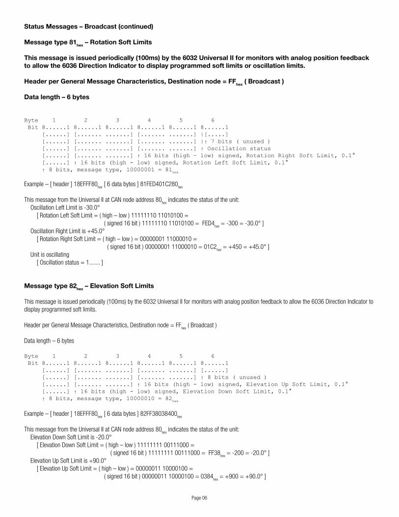
Message type 81hex – Rotation Soft Limits
This message is issued periodically (100ms) by the 6032 Universal II for monitors with analog position feedback to allow the 6036 Direction Indicator to display programmed soft limits or oscillation limits.
Header per General Message Characteristics, Destination node = FFhex ( Broadcast )
Data length – 6 bytes
Byte 1 2 3 4 5 6 Bit 8......1 8......1 8......1 8......1 8......1 8......1 [......] [....... .......] [....... .......] |[.....] [......] [....... .......] [....... .......] |↑ 7 bits ( unused ) [......] [....... .......] [....... .......] ↑ Oscillation status [......] [....... .......] ↑ 16 bits (high – low) signed, Rotation Right Soft Limit, 0.1° [......] ↑ 16 bits (high - low) signed, Rotation Left Soft Limit, 0.1° ↑ 8 bits, message type, 10000001 = 81
hex
Example–[header]18EFFF80hex[6databytes]81FED401C280
hex
ThismessagefromtheUniversalIIatCANnodeaddress80hex
indicates the status of the unit:OscillationLeftLimitis-30.0°[RotationLeftSoftLimit=(high–low)1111111011010100=(signed16bit)1111111011010100=FED4
hex=-300=-30.0°]
OscillationRightLimitis+45.0°[RotationRightSoftLimit=(high–low)=0000000111000010=(signed16bit)0000000111000010=01C2
hex=+450=+45.0°]
Unitisoscillating[Oscillationstatus=1.......]
Message type 82hex – Elevation Soft Limits
Thismessageisissuedperiodically(100ms)bythe6032UniversalIIformonitorswithanalogpositionfeedbacktoallowthe6036DirectionIndicatortodisplay programmed soft limits.
HeaderperGeneralMessageCharacteristics,Destinationnode=FFhex(Broadcast)
Datalength–6bytes
Byte 1 2 3 4 5 6 Bit 8......1 8......1 8......1 8......1 8......1 8......1 [......] [....... .......] [....... .......] [......] [......] [....... .......] [....... .......] ↑ 8 bits ( unused ) [......] [....... .......] ↑ 16 bits (high - low) signed, Elevation Up Soft Limit, 0.1° [......] ↑ 16 bits (high - low) signed, Elevation Down Soft Limit, 0.1° ↑ 8 bits, message type, 10000010 = 82
hex
Example–[header]18EFFF80hex[6databytes]82FF38038400
hex
ThismessagefromtheUniversalIIatCANnodeaddress80hex
indicates the status of the unit:ElevationDownSoftLimitis-20.0°[ElevationDownSoftLimit=(high–low)1111111100111000=(signed16bit)1111111100111000=FF38
hex=-200=-20.0°]
ElevationUpSoftLimitis+90.0°[ElevationUpSoftLimit=(high–low)=0000001110000100=(signed16bit)0000001110000100=0384
hex=+900=+90.0°]
Page07
Status Messages – Broadcast (continued)
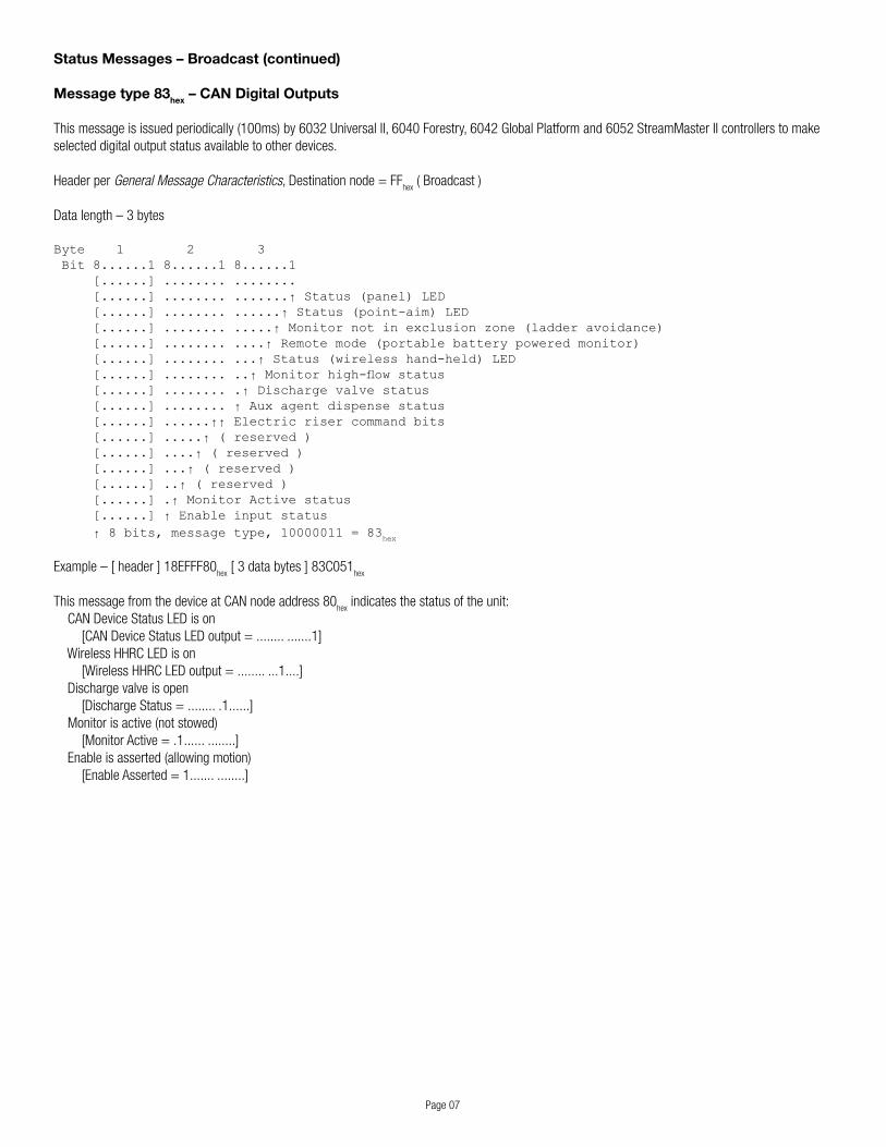
Message type 83hex – CAN Digital Outputs
Thismessageisissuedperiodically(100ms)by6032UniversalII,6040Forestry,6042GlobalPlatformand6052StreamMasterIIcontrollerstomakeselected digital output status available to other devices.
Header per General Message Characteristics,Destinationnode=FFhex(Broadcast)
Data length – 3 bytes
Byte 1 2 3 Bit 8......1 8......1 8......1 [......] ........ ........ [......] ........ .......↑ Status (panel) LED [......] ........ ......↑ Status (point-aim) LED [......] ........ .....↑ Monitor not in exclusion zone (ladder avoidance) [......] ........ ....↑ Remote mode (portable battery powered monitor) [......] ........ ...↑ Status (wireless hand-held) LED [......] ........ ..↑ Monitor high-flow status [......] ........ .↑ Discharge valve status [......] ........ ↑ Aux agent dispense status [......] ......↑↑ Electric riser command bits [......] .....↑ ( reserved ) [......] ....↑ ( reserved ) [......] ...↑ ( reserved ) [......] ..↑ ( reserved ) [......] .↑ Monitor Active status [......] ↑ Enable input status ↑ 8 bits, message type, 10000011 = 83
hex
Example–[header]18EFFF80hex[3databytes]83C051
hex
ThismessagefromthedeviceatCANnodeaddress80hex
indicates the status of the unit: CAN Device Status LED is on [CAN Device Status LED output = ........ .......1] Wireless HHRC LED is on [Wireless HHRC LED output = ........ ...1....] Discharge valve is open [Discharge Status = ........ .1......]Monitorisactive(notstowed) [Monitor Active = .1...... ........]Enableisasserted(allowingmotion) [Enable Asserted = 1....... ........]
Page08
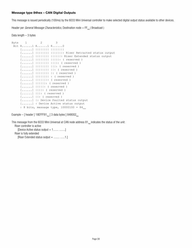
Message type 84hex – CAN Digital Outputs
Thismessageisissuedperiodically(100ms)bythe6033MiniUniversalcontrollertomakeselecteddigitaloutputstatusavailabletootherdevices.
Header per General Message Characteristics,Destinationnode=FFhex
(Broadcast)
Data length – 3 bytes
Byte 1 2 3 Bit 8......1 8......1 8......0 [......] |||||||| |||||||| [......] |||||||| |||||||↑ Riser Retracted status output [......] |||||||| ||||||↑ Riser Extended status output [......] |||||||| |||||↑ ( reserved ) [......] |||||||| ||||↑ ( reserved ) [......] |||||||| |||↑ ( reserved ) [......] |||||||| ||↑ ( reserved ) [......] |||||||| |↑ ( reserved ) [......] |||||||| ↑ ( reserved ) [......] |||||||↑ ( reserved ) [......] ||||||↑ ( reserved ) [......] |||||↑ ( reserved ) [......] ||||↑ ( reserved ) [......] |||↑ ( reserved ) [......] ||↑ ( reserved ) [......] |↑ Device Faulted status output [......] ↑ Device Active status output ↑ 8 bits, message type, 10000100 = 84
hex
Example–[header]18EFFF81hex
[3databytes]848002hex
Thismessagefromthe6033MiniUniversalatCANnodeaddress81hex
indicates the status of the unit: Riser controller is active [Device Active status output = 1....... ........] Riser is fully extended [Riser Extended status output = ........ ......1.]
Page09
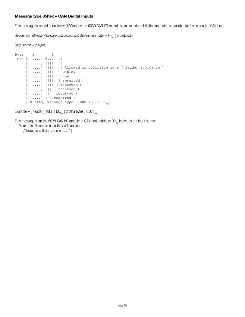
Message type 85hex – CAN Digital Inputs
Thismessageisissuedperiodically(100ms)bythe6039CANI/OmoduletomakeexternaldigitalinputstatusavailabletodevicesontheCANbus.
Header per General Message Characteristics,Destinationnode=FFhex
(Broadcast)
Datalength–2bytes
Byte 1 2 Bit 8......1 8......1 [......] |||||||| [......] |||||||↑ Allowed in collision zone ( ladder avoidance ) [......] ||||||↑ Deploy [......] |||||↑ Stow [......] ||||↑ ( reserved ) [......] |||↑ ( reserved ) [......] ||↑ ( reserved ) [......] |↑ ( reserved ) [......] ↑ ( reserved ) ↑ 8 bits, message type, 10000101 = 85
hex
Example–[header]18EFFFD0hex[2databytes]8501
hex
Thismessagefromthe6039CANI/OmoduleatCANnodeaddressD0hex
indicates the input status: Monitor is allowed to be in the collision zone [Allowed in collision zone = .......1]

Page10
Status Messages – Poll / Response
J1939 PGN 59904 – Field Request
Header 2 2 2 1 1 0 0 0 Bit 9...5 4......7 6......9 8......1 [.]|| [......] [......] [......] [.]|| [......] [......] ↑ 8 bits, Source node address [.]|| [......] ↑ 8 bits, PDU specific, Destination node ( FF
hex if Broadcast )
[.]|| ↑ 8 bits, PDU format, 11101010 = EAhex = 234 = PGN EA00
hex = 59904
[.]|↑ 1 bit, Data Page, 0 [.]↑ 1 bit, Extended Data Page, 0 ↑ 3 bits, Priority, 110 = 6
Data length – 3 bytes
Byte 1 2 3Bit 8......1 8......1 8......1 [....... ........ .......] ↑ 24 bits, PGN, ( low – mid – high ) 00000000 11101110 00000000 = ( unsigned 24 bit ) 00000000 11101110 00000000 = EE00hex = 60928 = Name field
Example–[header]18EAFFFEhex[3databytes]00EE00hex
Thismessagerequestsall(capable)devicestobroadcasttheirJ1939Namefield.
NotethatAkronBrassdevicessupportthisrequestonlyfortheNamefield,PGN60928(EE00hex).

Page 11
Status Messages – Poll / Response (continued)
J1939 PGN 60928 – Name Field
Header 2 2 2 1 1 0 0 0 Bit 9...5 4......7 6......9 8......1 [.]|| [......] [......] [......] [.]|| [......] [......] ↑ 8 bits, Source node address [.]|| [......] ↑ 8 bits, PDU specific, Destination node, 11111111 = FF
hex = Broadcast
[.]|| ↑ 8 bits, PDU format, 11101110 = EEhex = 238 = PGN EE00
hex = 60928
[.]|↑ 1 bit, Data Page, 0 [.]↑ 1 bit, Extended Data Page, 0 ↑ 3 bits, Priority, 110 = 6
Data length – 8 bytes
Byte 1 2 3 4 5 6 7 8 Bit 8......1 8......1 8......1 8......1 8......1 8......1 8......1 8......1 [......] [......] [.][...] [......] [...][.] [......] [.....]| |[.][..] [......] [......] [.][...] [......] [...][.] [......] [.....]| |[.]↑ 4 bits, System Instance [......] [......] [.][...] [......] [...][.] [......] [.....]| |↑ 3 bits, Industry Group [......] [......] [.][...] [......] [...][.] [......] [.....]| ↑ 1 bit, Arbitrary Address Capable [......] [......] [.][...] [......] [...][.] [......] [.....]↑ 1 bit, Reserved, 0 [......] [......] [.][...] [......] [...][.] [......] ↑ 7 bits, Vehicle System [......] [......] [.][...] [......] [...][.] ↑ 8 bits, Function [......] [......] [.][...] [......] [...]↑ 3 bits, ECU Instance [......] [......] [.][...] [......] ↑ 5 bits, Function Instance [......] [......] [.][...] ↑ 8 bits, Manufacturer Code (high) [......] [......] [.]↑ 5 bits, Identity Number (high) [......] [......] ↑ 3 bits, Manufacturer Code (low) [......] ↑ 8 bits, Identity Number (mid) ↑ 8 bits, Identity Number (low)
Example–[header]18EEFF80hex[8databytes]0B1AC22800420090
hex
ThismessagefromthedeviceatCANnodeaddress80hex
decodes as follows:ArbitraryAddressCapable=1.……=1(deviceusesaddressclaiming)IndustryGroup=.001….=…..001=01
hex=1(On-HighwayEquipment)
SystemInstance=….0000=00hex=0
VehicleSystem=0000000.=.000000=00hex=0
Function=01000010=42hex=66(I/OController)
FunctionInstance=00000…=…00000=00hex=0
ECUInstance=…..000=00hex=0
ManufacturerCode=(low–high)=110…..00101000=(unsigned11bit)…..00101000110=146
hex=326(AkronBrass)
IdentityNumber(low–high)=0000101100011010…00010=(unsigned21bit)...000100001101000001011=021A0B
hex =
Low21bitsofPINdigits7-15fieldofrecordtypeFFhexforPIN‘1032AE100801035’
(usedtomakeNAMEfieldasuniqueaspossibleperSAEJ1939-81NetworkManagement)
Page12
Status Messages – Poll / Response (continued)
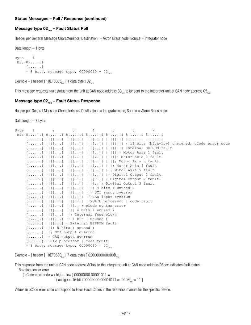
Message type 02hex – Fault Status Poll
Header per General Message Characteristics, Destination = Akron Brass node, Source = Integrator node
Data length – 1 byte
Byte 1 Bit 8......1 [......] ↑ 8 bits, message type, 00000010 = 02
hex
Example–[header]18EF8005hex[1databyte]02
hex
ThismessagerequestsfaultstatusfromtheunitatCANnodeaddress80hextobesenttotheIntegratorunitatCANnodeaddress05
hex.
Message type 02hex – Fault Status Response
Header per General Message Characteristics, Destination = Integrator node, Source = Akron Brass node
Data length – 7 bytes
Byte 1 2 3 4 5 6 7 Bit 8......1 8......1 8......1 8......1 8......1 8......1 8......1 [......] |||[...] |||[..]| |||[..]| |||||||| [....... .......] [......] |||[...] |||[..]| |||[..]| |||||||| ↑ 16 bits (high-low) unsigned, pCode error code [......] |||[...] |||[..]| |||[..]| |||||||↑ Internal EEPROM fault [......] |||[...] |||[..]| |||[..]| ||||||↑ Motor Axis 1 fault [......] |||[...] |||[..]| |||[..]| |||||↑ Motor Axis 2 fault [......] |||[...] |||[..]| |||[..]| ||||↑ Motor Axis 3 fault [......] |||[...] |||[..]| |||[..]| |||↑ Motor Axis 4 fault [......] |||[...] |||[..]| |||[..]| ||↑ Motor Axis 5 fault [......] |||[...] |||[..]| |||[..]| |↑ Digital Output 1 fault [......] |||[...] |||[..]| |||[..]| ↑ Digital Output 2 fault [......] |||[...] |||[..]| |||[..]↑ Digital Output 3 fault [......] |||[...] |||[..]| |||↑ 4 bits ( unused ) [......] |||[...] |||[..]| ||↑ SCI input overrun [......] |||[...] |||[..]| |↑ CAN input overrun [......] |||[...] |||[..]| ↑ XGATE processor | code fault [......] |||[...] |||[..]↑ pCode syntax error [......] |||[...] |||↑ 4 bits ( unused ) [......] |||[...] ||↑ Internal fuse blown [......] |||[...] |↑ 1 bit ( unused ) [......] |||[...] ↑ External EEPROM fault [......] |||↑ 5 bits ( unused ) [......] ||↑ SCI output overrun [......] |↑ CAN output overrun [......] ↑ S12 processor | code fault ↑ 8 bits, message type, 00000010 = 02
hex
Example–[header]18EF0580hex[7databytes]0200000000000B
hex
ThisresponsefromtheunitatCANnodeaddress80hextotheIntegratorunitatCANnodeaddress05hexindicatesfaultstatus: Rotation sensor error[pCodeerrorcode=(high–low)0000000000001011=(unsigned16bit)0000000000001011=000B
hex = 11 ]
ValuesinpCodeerrorcodecorrespondtoErrorFlashCodesinthereferencemanualforthespecificdevice.
Page 13
Status Messages – Poll / Response (continued)
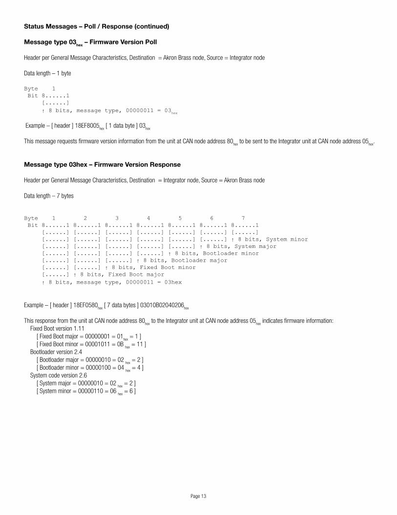
Message type 03hex – Firmware Version Poll
Header per General Message Characteristics, Destination = Akron Brass node, Source = Integrator node
Data length – 1 byte
Byte 1 Bit 8......1 [......] ↑ 8 bits, message type, 00000011 = 03
hex
Example–[header]18EF8005hex[1databyte]03
hex
ThismessagerequestsfirmwareversioninformationfromtheunitatCANnodeaddress80hextobesenttotheIntegratorunitatCANnodeaddress05
hex.
Message type 03hex – Firmware Version Response
Header per General Message Characteristics, Destination = Integrator node, Source = Akron Brass node
Data length – 7 bytes
Byte 1 2 3 4 5 6 7 Bit 8......1 8......1 8......1 8......1 8......1 8......1 8......1 [......] [......] [......] [......] [......] [......] [......] [......] [......] [......] [......] [......] [......] ↑ 8 bits, System minor [......] [......] [......] [......] [......] ↑ 8 bits, System major [......] [......] [......] [......] ↑ 8 bits, Bootloader minor [......] [......] [......] ↑ 8 bits, Bootloader major [......] [......] ↑ 8 bits, Fixed Boot minor [......] ↑ 8 bits, Fixed Boot major ↑ 8 bits, message type, 00000011 = 03hex
Example–[header]18EF0580hex[7databytes]03010B02040206
hex
ThisresponsefromtheunitatCANnodeaddress80hextotheIntegratorunitatCANnodeaddress05
hex indicates firmware information:
FixedBootversion1.11[FixedBootmajor=00000001=01
hex = 1 ]
[FixedBootminor=00001011=0Bhex
= 11 ]Bootloaderversion2.4[Bootloadermajor=00000010=02
hex=2]
[Bootloaderminor=00000100=04hex=4]
Systemcodeversion2.6[Systemmajor=00000010=02
hex=2]
[Systemminor=00000110=06hex=6]
Page14
Status Messages – Poll / Response (continued)
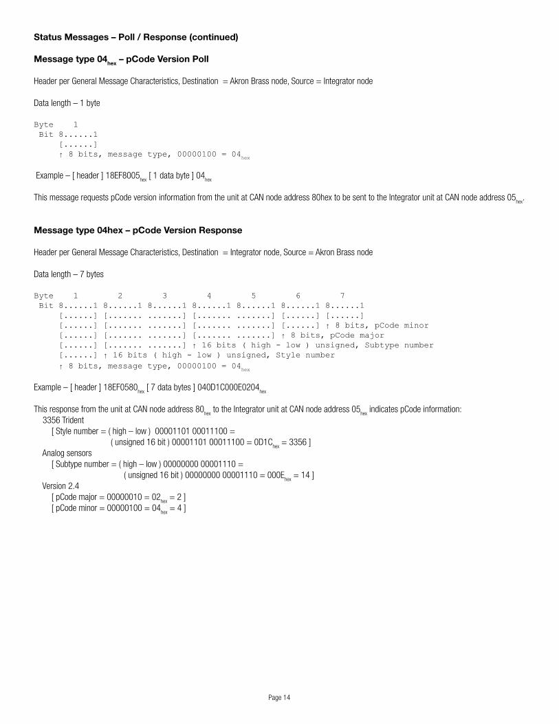
Message type 04hex – pCode Version Poll
Header per General Message Characteristics, Destination = Akron Brass node, Source = Integrator node
Data length – 1 byte
Byte 1 Bit 8......1 [......] ↑ 8 bits, message type, 00000100 = 04
hex
Example–[header]18EF8005hex[1databyte]04
hex
ThismessagerequestspCodeversioninformationfromtheunitatCANnodeaddress80hextobesenttotheIntegratorunitatCANnodeaddress05hex
.
Message type 04hex – pCode Version Response
Header per General Message Characteristics, Destination = Integrator node, Source = Akron Brass node
Data length – 7 bytes
Byte 1 2 3 4 5 6 7 Bit 8......1 8......1 8......1 8......1 8......1 8......1 8......1 [......] [....... .......] [....... .......] [......] [......] [......] [....... .......] [....... .......] [......] ↑ 8 bits, pCode minor [......] [....... .......] [....... .......] ↑ 8 bits, pCode major [......] [....... .......] ↑ 16 bits ( high - low ) unsigned, Subtype number [......] ↑ 16 bits ( high - low ) unsigned, Style number ↑ 8 bits, message type, 00000100 = 04
hex
Example–[header]18EF0580hex[7databytes]040D1C000E0204
hex
ThisresponsefromtheunitatCANnodeaddress80hextotheIntegratorunitatCANnodeaddress05
hex indicates pCode information:
3356Trident[Stylenumber=(high–low)0000110100011100=(unsigned16bit)0000110100011100=0D1C
hex=3356]
Analog sensors[Subtypenumber=(high–low)0000000000001110=(unsigned16bit)0000000000001110=000E
hex=14]
Version2.4[pCodemajor=00000010=02
hex=2]
[pCodeminor=00000100=04hex=4]

Page 15
Status Messages – Poll / Response (continued)
Message type 05hex – Config Version Poll
Header per General Message Characteristics, Destination = Akron Brass node, Source = Integrator node
Data length – 1 byte
Byte 1 Bit 8......1 [......] ↑ 8 bits, message type, 00000101 = 05
hex
Example–[header]18EF8005hex[1databyte]05
hex
ThismessagerequestsconfigversioninformationfromtheunitatCANnodeaddress80hextobesenttotheIntegratorunitatCANnodeaddress05
hex.
Message type 05hex – Config Version Response
Header per General Message Characteristics, Destination = Integrator node, Source = Akron Brass node
Data length – 7 bytes
Byte 1 2 3 4 5 6 7 Bit 8......1 8......1 8......1 8......1 8......1 8......1 8......1 [......] [....... ........ ........ .......] [......] [......] [......] [....... ........ ........ .......] [......] ↑ 8 bits, Config minor [......] [....... ........ ........ .......] ↑ 8 bits, Config major [......] ↑ 32 bits ( high - low ) unsigned, Config type ↑ 8 bits, message type, 00000101 = 05
hex
Example–[header]18EF0580hex[7databytes]050398690E0204
hex
ThisresponsefromtheunitatCANnodeaddress80hextotheIntegratorunitatCANnodeaddress05
hex indicates Config information:
Trident, Novotechnik sensors[Configtype=(high–low)00000011100110000110100100001110=(unsigned32bit)00000011100110000110100100001110=0398690E
hex=60320014]
Version2.4[Configmajor=00000010=02
hex=2]
[Configminor=00000100=04hex=4]

Page16
Status Messages – Poll / Response (continued)
Message type 21hex – Data Poll for Vista
Thismessageisacceptedby6032UniversalIIcontrollerstoprovideforthedisplayofcertaininformationonaspecificallyprogrammedVistadisplay.
Header per General Message Characteristics, Destination = Monitor node, Source = Vista node
Data length – 1 byte
Byte 1 Bit 8......1 [......] ↑ 8 bits, message type, 00100001 = 21
hex
Example–[header]18EF8005hex[1databyte]21
hex
ThismessagefromtheVistadisplayatCANnodeaddress05hexrequeststhemonitoratCANnodeaddress80
hex to provide certain information via one
type21hexrecordandonetype22
hex record.

Page 17
Message type 21hex – Data Response for Vista
Header per General Message Characteristics, Destination = Vista node, Source = Monitor node
Data length – 8 bytes
Byte 1 2 3 4 5 6 7 8 Bit 8......1 8......1 8......1 8......1 8......1 8......1 8......1 8......1 [......] [....... .]|||||| |||||||| [....... .]|||||| [....... .]|||||↑ Joystick X right positive [......] [....... .]|||||| |||||||| [....... .]|||||| [....... .]||||↑ Joystick X left negative [......] [....... .]|||||| |||||||| [....... .]|||||| [....... .]|||↑ Joystick Y back negative [......] [....... .]|||||| |||||||| [....... .]|||||| [....... .]||↑ Joystick Y fwd positive [......] [....... .]|||||| |||||||| [....... .]|||||| [....... .]|↑ Joystick sw1 [......] [....... .]|||||| |||||||| [....... .]|||||| [....... .]↑ Joystick sw2 [......] [....... .]|||||| |||||||| [....... .]|||||| ↑ Joystick Y position, 10 bits ( hi-lo ) [......] [....... .]|||||| |||||||| [....... .]|||||↑ Joystick sw3 [......] [....... .]|||||| |||||||| [....... .]||||↑ Joystick sw10 [......] [....... .]|||||| |||||||| [....... .]|||↑ ( reserved ) [......] [....... .]|||||| |||||||| [....... .]||↑ ( reserved ) [......] [....... .]|||||| |||||||| [....... .]|↑ ( reserved ) [......] [....... .]|||||| |||||||| [....... .]↑ ( reserved ) [......] [....... .]|||||| |||||||| ↑ Joystick X position, 10 bits ( hi-lo ) [......] [....... .]|||||| |||||||↑ Digital input 1 [......] [....... .]|||||| ||||||↑ Digital input 2H [......] [....... .]|||||| |||||↑ Digital input 2L [......] [....... .]|||||| ||||↑ Digital input 3H [......] [....... .]|||||| |||↑ Digital input 3L [......] [....... .]|||||| ||↑ Digital input 4H [......] [....... .]|||||| |↑ Digital input 4L [......] [....... .]|||||| ↑ Digital input 5H [......] [....... .]|||||↑ Digital input 5L [......] [....... .]||||↑ Digital output 1 [......] [....... .]|||↑ Digital output 2 [......] [....... .]||↑ Digital output 3 [......] [....... .]|↑ K1 relay set [......] [....... .]↑ K1 relay reset [......] ↑ System voltage, 10 bits ( hi-lo ) ↑ 8 bits, message type, 00100001 = 21
hex
This response data is formatted for use by a specifically programmed Vista display.
Message type 22hex – Data Response for Vista
Header per General Message Characteristics, Destination = Vista node, Source = Monitor node
Data length – 5 bytes
Byte 1 2 3 4 5 Bit 8......1 8......1 8......1 8......1 8......1 [......] [....... .......] [....... .......] [......] [....... .......] ↑ Elevation position, 16 bits ( hi-lo ), unsigned scaled [......] ↑ Rotation position, 16 bits ( hi-lo ), unsigned scaled ↑ 8 bits, message type, 00100010 = 22
hex
This response data is formatted for use by a specifically programmed Vista display.
Page 18
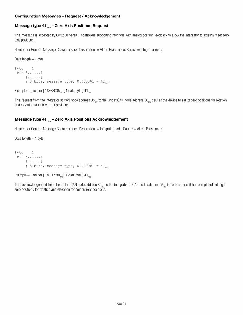
Configuration Messages – Request / Acknowledgement
Message type 41hex – Zero Axis Positions Request
Thismessageisacceptedby6032UniversalIIcontrollerssupportingmonitorswithanalogpositionfeedbacktoallowtheintegratortoexternallysetzeroaxis positions.
Header per General Message Characteristics, Destination = Akron Brass node, Source = Integrator node
Data length – 1 byte
Byte 1 Bit 8......1 [......] ↑ 8 bits, message type, 01000001 = 41
hex
Example–[header]18EF8005hex[1databyte]41
hex
ThisrequestfromtheintegratoratCANnodeaddress05hextotheunitatCANnodeaddress80
hex causes the device to set its zero positions for rotation
and elevation to their current positions.
Message type 41hex – Zero Axis Positions Acknowledgement
Header per General Message Characteristics, Destination = Integrator node, Source = Akron Brass node
Data length – 1 byte
Byte 1 Bit 8......1 [......] ↑ 8 bits, message type, 01000001 = 41
hex
Example–[header]18EF0580hex[1databyte]41
hex
ThisacknowledgementfromtheunitatCANnodeaddress80hextotheintegratoratCANnodeaddress05
hex indicates the unit has completed setting its
zero positions for rotation and elevation to their current positions.

Page 19
Configuration Messages – Request / Acknowledgement (continued)
Message type 45hex – Reset Controller
Thismessageisacceptedby6032UniversalII,6040Forestry,6042GlobalPlatformand6052StreamMasterIIcontrollers.Uponreceipt,theyperforman immediate system reset.
Header per General Message Characteristics, Destination = Akron Brass node, Source = Integrator node
Data length – 1 byte
Byte 1 Bit 8......1 [......] ↑ 8 bits, message type, 01000101 = 45
hex
Example–[header]18EF8005hex[1databyte]45
hex
ThisrequestfromtheintegratoratCANnodeaddress05hex
totheunitatCANnodeaddress80hex
causes the device to reset and perform normal powerupactions(addressclaim,AkronBrassannouncement,etc.).
Note that this request is not acknowledged.

Page20
Configuration Messages – Request / Acknowledgement (continued)
Message type 46hex – Enter Controller Setup Mode
Thismessageisacceptedby6032UniversalII,6040Forestry,6042GlobalPlatformand6052StreamMasterIIcontrollers.Itcausesthecontrollertoenter its setup mode.
Header per General Message Characteristics, Destination = Akron Brass node, Source = Integrator node
Data length – 1 byte
Byte 1 Bit 8......1 [......] ↑ 8 bits, message type, 01000110 = 46
hex
Example–[header]18EF8005hex[1databyte]46
hex
ThisrequestfromtheintegratoratCANnodeaddress05hex
totheunitatCANnodeaddress80hex
causes the device to immediately enter its setup mode.
Note that this is functionally equivalent to activating the Pattern Stream input at powerup.
Message type 46hex – Enter Controller Setup Mode Acknowledgement
Header per General Message Characteristics, Destination = Integrator node, Source = Akron Brass node
Data length – 1 byte
Byte 1 Bit 8......1 [......] ↑ 8 bits, message type, 01000110 = 46
hex
Example–[header]18EF0580hex
[1databyte]46hex
ThisacknowledgementfromtheunitatCANnodeaddress80hex
totheintegratoratCANnodeaddress05hex
indicates the unit has accepted the request to enter setup mode.
Page21
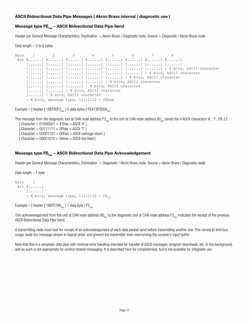
ASCII Bidirectional Data Pipe Messages ( Akron Brass internal / diagnostic use )
Message type FEhex – ASCII Bidirectional Data Pipe Send
Header per General Message Characteristics, Destination = Akron Brass | Diagnostic node, Source = Diagnostic | Akron Brass node
Datalength–2to8bytes
Byte 1 2 3 4 5 6 7 8 Bit 8......1 8......1 8......1 8......1 8......1 8......1 8......1 8......1 [......] [......] [......] [......] [......] [......] [......] [......] [......] [......] [......] [......] [......] [......] [......] ↑ 8 bits, ASCII character [......] [......] [......] [......] [......] [......] ↑ 8 bits, ASCII character [......] [......] [......] [......] [......] ↑ 8 bits, ASCII character [......] [......] [......] [......] ↑ 8 bits, ASCII character [......] [......] [......] ↑ 8 bits, ASCII character [......] [......] ↑ 8 bits, ASCII character [......] ↑ 8 bits, ASCII character ↑ 8 bits, message type, 11111110 = FEhex
Example–[header]18EF80F2hex[5databytes]FE413F0D0A
hex
ThismessagefromthediagnostictoolatCANnodeaddressF2hextotheunitatCANnodeaddress80
hexsendsthe4ASCIIcharacters‘A’,‘?’,CR,LF.
[Character=01000001=41hex=ASCII‘A’][Character=00111111=3Fhex=ASCII‘?’][Character=00001101=0Dhex=ASCIIcarriagereturn][Character=00001010=0Ahex=ASCIIlinefeed]
Message type FEhex – ASCII Bidirectional Data Pipe Acknowledgement
Header per General Message Characteristics, Destination = Diagnostic | Akron Brass node, Source = Akron Brass | Diagnostic node
Data length – 1 byte
Byte 1 Bit 8......1 [......] ↑ 8 bits, message type, 11111110 = FE
hex
Example–[header]18EFF280hex[1databyte]FE
hex
ThisacknowledgementfromtheunitatCANnodeaddress80hextothediagnostictoolatCANnodeaddressF2
hex indicates the receipt of the previous
ASCII Bidirectional Data Pipe Send.
A transmitting node must wait for receipt of an acknowledgement of each data packet send before transmitting another one. This serves to limit bus usage,keepthemessagestreaminlogicalorder,andpreventthetransmitterfromoverrunningthereceiver’sinputbuffer.
Note that this is a simplistic data pipe with minimal error handling intended for transfer of ASCII messages, program downloads, etc. in the background, and as such is not appropriate for control-related messaging. It is described here for completeness, but is not available for integrator use.

Page22
Appendix A – Address Claiming
Address claiming, detailed in SAE J1939-81 Network Management, is the technique used by Akron Brass controllers and display devices to acquire a nodeaddressontheCANnetwork.Itisgenerallycompatiblewithdevicesusingfixednodeaddresses,asthefixednodeaddressrangeis7Fhexandbelow,withthedynamicaddressrange80hexandabove.AkronBrassdevicesstartclaimingaddressesat80hex,soaslongasintegratordevicesusenodeaddresseslessthan80hex,oruseaddressclaiming,therearenonodeaddressingconflicts.
Thenegotiationnormallytakesplacewithin2-3secondsofsystempowerup,butif‘hotpluggable’devicesareaddedtothebuslater,itcanoccuragainat that time. The J1939 spec defines a priority scheme that includes the possibility of a device successfully claiming an address, and then later losing it to a higher priority device.
Toaddressthisandrelievetheintegratorofconcernsaboutthespecificmechanicsofaddressclaiming,AkronBrassdevicesissueatypeFFhex‘Ad-dressAnnouncement’messageuponsuccessfuladdressclaim.Iftheylosetheiraddresslaterandmustclaimanother,theyagainissuetheAddressAnnouncement.Theinterestedintegratornode(s)shouldlistenforthismessageanduseitssourcenodeaddresstoupdatetheirnodeaddressfortheAkron Brass device.
In the case of multiple Akron Brass devices on a CAN bus, it is up to the integrator to use the PIN field of the address announcement to differentiate amongthem.Onesuggestedwaytodothisistohavetheintegratordevice‘remember’theidentityofaspecificAkronBrassdevice,andusethattoselect the address announcement to use for the node address of the device of interest.
Thefirst4digitsofthePINareusedtoidentifytheAkronBrassdevicetype:
1032–6032UniversalII1033–6033MiniUniversal1034–6034OperatorStation1035–6035Joystick(andsome6041Switchboxes)1036–6036DirectionIndicator1037–6037WirelessInterface1040–6040Forestrycontroller1041–6041Switchbox(andsome6035Joysticks)1042–6042GlobalPlatformcontroller(PortableElectricmonitoret.al.)1051–6051CANGateway1052–6052StreamMasterII
Iftheintegratorforsomereasoncannot(ordoesnotwantto)processCANmessagesearlyenoughtoseetheaddressannouncementsatpowerup,theycanbroadcasttheJ1939NameRequest(seeStatusMessages–Poll/Response,J1939PGN59904–FieldRequest).Inresponsetothismes-sage,alladdresseddeviceswhichhaveclaimedaddresseswillbroadcastaJ1939Nameresponse(seeStatusMessages–Poll/Response,J1939PGN60928–NameField)withtheirinformation(thesemaybeignored).Aftertheysendthisresponse,AkronBrassdeviceswilladditionallybroadcastamessagetypeFFhexaddressannouncement,whichtheintegratorcanthenprocessasrequired.

Page23
Appendix B – Handling of Joystick Input Data
Joystickinputsaremappedto6032UniversalII,6040Forestryand6042GlobalPlatforminputsasfollows:
X axis right - Rotate Right with proportional speed control X axis left - Rotate Left with proportional speed controlYaxisback-ElevateUpwithproportionalspeedcontrol Y axis forward - Elevate Down with proportional speed control Switch 1 - Pattern StreamSwitch2-PatternFogSwitch3-DischargeOnSwitch4-OscillateOn|SetSwitch5-FlowHighSwitch6-FlowLowSwitch7-OscillatePause|Resume Switch 8 - Deploy Switch 9 - StowSwitch10-DischargeOffSwitch11-CAFSdrymodeSwitch12-CAFSwetmodeExtended(optional)GripXaxis–PointAimrotationtargetposition(±100%=±175°)GripYaxis–PointAimelevationtargetposition(±100%=±90°)Switch13–(reserved)Switch14–(reserved)Switch15–(reserved)Switch16–(reserved)
The units will accept input requests from multiple sources and will try to honor any and all non-conflicting requests. Conflicting requests will be handled accordingtothefollowingdefaultpriorityscheme(meaninginputrequestsfromaparticularsourcewilloverrideconflictingrequestsfromalllowerprior-itysources):
Highest priorityPhysicalinputswitches(onlyavailableon6032UniversalII) CAN device at node address 33
hex
CANdeviceatnodeaddress34hex
CAN device at node address 35hex
CANdeviceatnodeaddress36hex
CAN device at node address 37hex
CAN device at node address 38hex
Lowest priority
Bydefault,allcontroldevices[6035Joystick,6037WirelessInterface,6041Switchbox,andanyintegratordevice(s)]appeartoAkronBrasscontrollersasaJ1939joystickatoneoftheaboveaddressesbroadcastingJ1939PGN64982messages.
J1939joysticksbroadcasttheirmessagesonaperiodicbasis,every100msorless(AkronBrasscontroldevicesdefaulttoevery20ms).Asasafetyprecaution against control device failure or CAN bus interruption, the controller monitors message timing and if it does not receive any message from an inputdevice(CANnodeaddress)for200ms,theinputbufferforthatCANnodeiscleared,stoppinganymanualmotionthatwasbeingrequestedbythatdevice.

Page24
Appendix C – Default Axis Usage for Akron Brass Devices
6032UniversalIIcontroller
Axis1:Rotation,(+)=right,(-)=left
Axis2:Elevation,(+)=up,(-)=down
Axis3:Pattern,(+)=stream,(-)=fog
Axis4:MonitorspecificTridentDualGallonage:Flowcontrol,(+)=highflow,(-)=lowflowDeckMaster:Swingarm,(+)=deploy,(-)=stowOthers:N/A
Axis5:Dischargevalve,(+)=open,(-)=close
6040Forestrycontroller
Axis1:Rotation,(+)=right,(-)=left
Axis2:Elevation,(+)=up,(-)=down
Axis3:Pattern,(+)=stream,(-)=fog
Axis4:Dischargevalve,(+)=open,(-)=close
6042GlobalPlatformcontroller
Axis1:Rotation,(+)=right,(-)=left
Axis2:Elevation,(+)=up,(-)=down
Axis3:Pattern,(+)=stream,(-)=fog
6052StreamMasterIIcontroller
Axis1:Rotation,(+)=right,(-)=left
Axis2:Elevation,(+)=up,(-)=down
Axis3:Pattern,(+)=stream,(-)=fog

ISO 9001 REGISTERED COMPANY
PHONE: 330.264.5678 or 800.228.1161 I FAX: 330.264.2944 or 800.531.7335 I www.akronbrass.com
WARRANTY AND DISCLAIMER: We warrant Akron Brass products for a period of five (5) years after purchase against defects in materials or workmanship. Akron Brass will repair or replace product which fails to satisfy this warranty. Repair or replacement shall be at the discretion of Akron Brass. Products must be promptly returned to Akron Brass for warranty service.
We will not be responsible for: wear and tear; any improper installation, use, maintenance or storage; negligence of the owner or user; repair or modification after delivery; damage; failure to follow our instructions or recommendations; or anything else beyond our control. WE MAKE NO WARRANTIES, EXPRESS OR IMPLIED, OTHER THAN THOSE INCLUDED IN THIS WARRANTY STATEMENT, AND WE DISCLAIM ANY IMPLIED WARRANTY OF MERCHANTABILITY OR FITNESS FOR ANY PARTICULAR PURPOSE. Further, we will not be responsible for any consequential, incidental or indirect damages (including, but not limited to, any loss of profits) from any cause whatsoever. No person has authority to change this warranty.
© Premier Farnell Corporation. 2012 All rights reserved. No portion of this can be reproduced without the express written consent of Premier Farnell Corporation.
revised: 1/16


![DCU 305 R3 CAN / J1939 Manual - Auto-Maskin§ [a] SAE, J1939-71 § [b] SAE, J1939-73 § [c] Conrad Etschberger, “Controller Area Network” ... CAN / J1939 Manual CAN / J1939 –](https://img.pdfslide.net/doc/110x75/5ae535d97f8b9a7b218f6863/dcu-305-r3-can-j1939-manual-auto-maskin-a-sae-j1939-71-b-sae-j1939-73.jpg)