Embed Size (px)
Citation preview


Sub Group on Advanced Biofuels
“Technology status and reliability of the value chains”
Compiled by:
Ingvar Landälv
Division of Energy Sciences,
Luleå University of Technology
Assisted by:
Freya Burton of Lanzatech
Francisco Girio of LNEG
Susanna Pflüger of EBA
Ilmari Lastikka of NESTE
Eelco Dekker of Methanol institute
Co-edited by:
Kyriakos Maniatis of DG ENER
Lars Waldheim, Independent Consultant
Eric van den Heuvel, studio Gear Up
Stamatis Kalligeros, Assistant Professor,
Hellenic Naval Academy
Date: 14 February 2017
Disclaimer
This report has been prepared for the Sub Group Advanced Biofuels (SGAB) based on the
information received from its members as background material and as such has been accepted
and used as working material by the Editorial Team to give the status of existing technologies
without the ambition of describing all developments in the area in detail. However, the view
and opinions in this report are of the SGAB and do not necessarily state or reflect those of the
Commission or the organization that are members of, or observers to the SGAB group.
References to products, processes, or services by trade name, trademark, manufacturer or
the like does not constitute or imply an endorsement or recommendation of these by the
Commission or the Organizations represented by the SGAB Members' and Observers Neither
the Commission nor any person acting on the Commission’s, or, the Organizations
represented by the SGAB Members' and Observers' behalf make any warranty, or assumes
any legal liability or responsibility for the accuracy, completeness, or usefulness of any
information contained herein.
Technology status and reliability of value chains | SGAB | Final
iii
Table of Contents
Disclaimer ................................................................................................................................. ii
Table of Contents .................................................................................................................... iii
Key Messages .......................................................................................................................... 1
1. Introduction ....................................................................................................................... 3
1.1 Background .............................................................................................................. 3
1.2 Structure ................................................................................................................... 3
1.3 Contributors .............................................................................................................. 4
1.4 Abbreviations ............................................................................................................ 6
2. Thermochemical conversion ............................................................................................. 7
2.1 Feedstocks ............................................................................................................... 7
2.2 Synthetic fuels via gasification .................................................................................. 8
2.2.1 Gasification ......................................................................................................... 8
2.2.2 Gas conditioning and clean up ........................................................................... 8
2.2.3 Product formation ............................................................................................... 9
2.2.3.1 Fischer-Tropsch (FT)-Liquids ...................................................................... 9
2.2.3.2 Methanol and Dimethyl Ether (DME) ........................................................... 9
2.2.3.3 Synthetic Gasoline ..................................................................................... 10
2.2.3.4 Product formation through biological gas fermentation ............................. 10
2.2.4 Pilots, Demonstration and Commercial plants .................................................. 10
2.2.4.1 The Bioliq pilot plant at Karlsruhe Institute of Technology (KIT), Germany ...
................................................................................................................... 10
2.2.4.2 The BioDME plant in Piteå, Sweden ......................................................... 11
2.2.4.3 The GTI gasification based pilot plant, Des Plaines, USA ......................... 12
2.2.4.4 Enerkem’s Demonstration Plant, Westbury, Quebec, Canada .................. 13
2.2.4.5 Enerkem’s first commercial Plant, Edmonton, Canada ............................. 14
2.2.4.6 The Sunshine Kaidi New Energy Group pilot (China) and demonstration
(Finland) ................................................................................................................... 15
2.2.5 Project under construction ................................................................................ 16
2.2.5.1 The BioTfueL pilot plant, France ............................................................... 16
2.3 Bio-methane via gasification ................................................................................... 18
2.3.1 Gasification ....................................................................................................... 18
2.3.2 Gas conditioning and clean up ......................................................................... 18
2.3.3 Product formation ............................................................................................. 19
2.3.4 Pilots, Demonstration and Commercial plants .................................................. 19
2.3.4.1 Biomass CHP Güssing, Austria ................................................................. 19

Technology status and reliability of value chains | SGAB | Final
iv
2.3.4.2 The GoBiGas plant in Gothenburg, Sweden ............................................. 20
2.3.4.3 The “Gogreengas” Pilot Plant, Swindon, UK ............................................. 20
2.4 Production and upgrading of pyrolysis products and lignin rich fractions ............... 22
2.4.1 Pyrolysis ........................................................................................................... 22
2.4.2 New technology developments – Upgrading/Co-processing of pyrolysis oil and
other lignin rich fractions ................................................................................................. 23
2.4.2.1 Via pyrolysis oil and torrefaction ................................................................ 23
2.4.2.2 Via fraction of lignin ................................................................................... 24
2.4.3 Pilots (P), Demonstration (D) and Commercial (C) plants ................................ 24
2.4.3.1 The Bioliq plant at KIT, Germany .............................................................. 24
2.4.3.2 The Fortum plant in Joensuu, Finland ....................................................... 24
2.4.3.3 The Empyro plant, Hengelo, Holland ......................................................... 25
2.4.3.4 ENSYN plant in Renfrew, Canada ............................................................. 26
2.5 Upgrading of a wide variety of wastes and residues to Hydrotreated Vegetable Oils
(HVO) ................................................................................................................................ 27
2.5.1 HVO Stand-alone production facilities .............................................................. 27
2.5.2 HVO production through refinery conversion .................................................... 28
2.5.3 Co-processing ................................................................................................... 28
2.5.4 Pilots, Demonstrations and Commercial Plants ................................................ 28
2.5.4.1 Neste ......................................................................................................... 28
2.5.4.2 UPM’s Lappeenranta Biorefinery plant, in Lappeenranta, Finland ............ 29
2.5.4.3 Diamond Green Diesel, Louisiana (USA) .................................................. 30
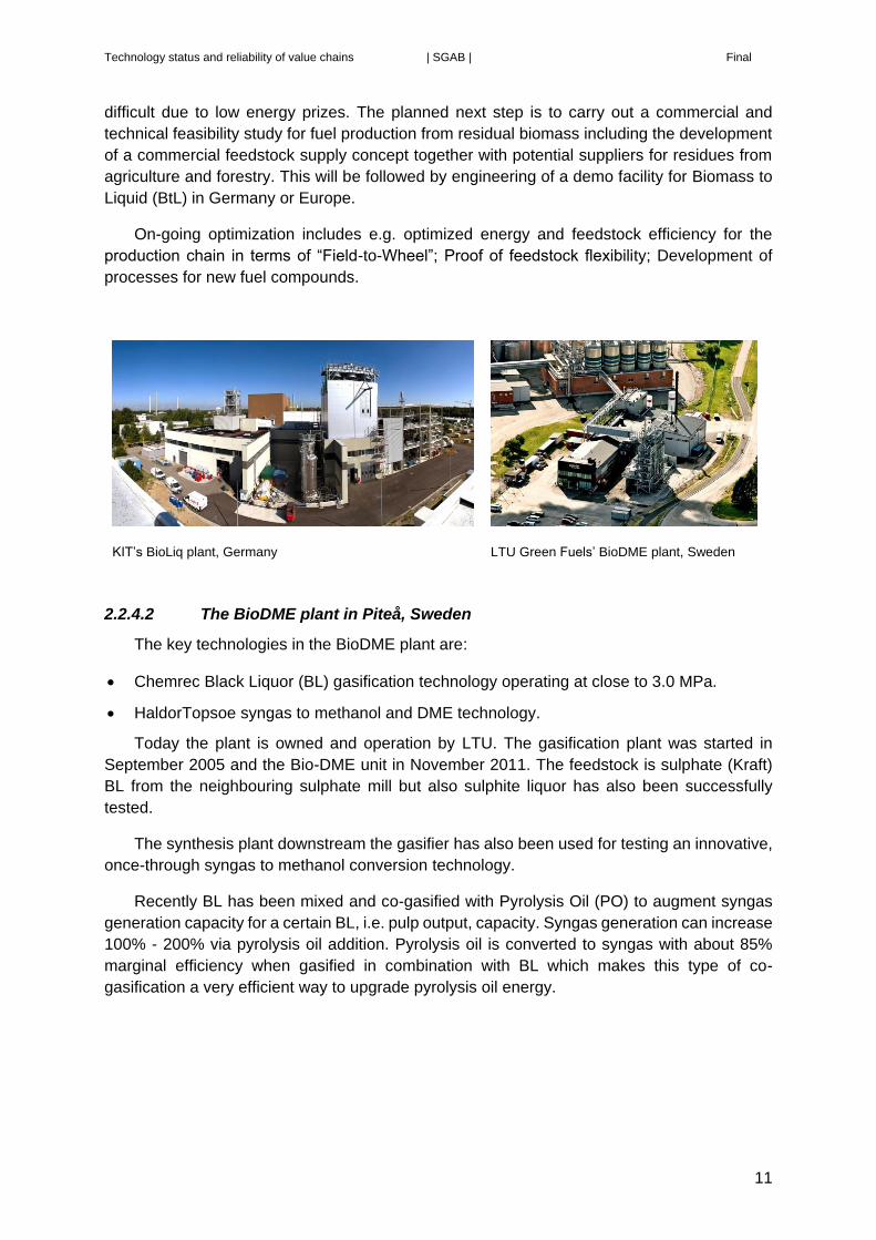
2.5.4.4 Eni’s Green Refinery Project, Venice, Italy ................................................ 30
2.5.4.5 The AltAir Renewable Jet Fuel Project, Los Angeles, USA ....................... 31
2.5.5 New Technology Developments ....................................................................... 31
3. Biochemical conversion .................................................................................................. 33
3.1 Feedstock (for alcohols and hydrocarbons) ............................................................ 33
3.2 Ethanol and higher alcohols from lignocellulosic sugar via fermentation ............... 33
3.2.1 Yeast fermentation to ethanol ........................................................................... 33
3.2.2 Yeast fermentation to butanol ........................................................................... 34
3.2.3 Microbial Fermentation via Acetic Acid ............................................................. 35
3.2.4 Pilots, Demonstration and Commercial plants .................................................. 35
3.2.4.1 The Hugoton Plant, Kansas, USA ............................................................. 35
3.2.4.2 Crescentino plant, Italy .............................................................................. 36
3.2.4.3 DuPont’s Nevada Plant, Iowa, USA .......................................................... 37
3.2.4.4 GranBio’s Bioflex 1 Plant, Alagoas, Brazil. ................................................ 37

Technology status and reliability of value chains | SGAB | Final
v
3.2.4.5 Raizen (Shell, Cosan), IOGEN, Costa Pinto, SP, Brazil ............................ 38
3.2.4.6 POET-DSM Liberty Plant, USA ................................................................ 39
3.2.4.7 The SEKAB Plant, Sweden ....................................................................... 40
3.2.4.8 The Butamax plant, United Kingdom ......................................................... 40
3.2.4.9 The Inbicon plant, Denmark ...................................................................... 41
3.2.4.10 The Borregaard plant, Norway .................................................................. 42
3.2.4.11 IFP’s Futurol pilot, Pomacle, France ......................................................... 43
3.2.4.12 IFP’s Futurol Demonstration, Bucy-le-Long, France ................................. 43
3.2.4.13 Clariant development plant, Straubing, Germany ...................................... 44
3.2.4.14 Cellunolix® demonstration plant, Kajaani, Finland .................................... 45
3.3 Hydrocarbons from sugar-containing material via biological and/or chemical
processes ........................................................................................................................... 46
3.3.1 Via microbial fermentation Farnesene .............................................................. 46
3.3.2 Routes involving catalytic upgrading of sugars or platform chemicals that can be
produced from sugars ..................................................................................................... 46
3.3.3 Catalytic Reforming .......................................................................................... 47
3.3.4 Pilots, Demonstration and Commercial plants .................................................. 47
3.3.4.1 The Virent plant, USA ................................................................................ 47
3.3.4.2 The Swedish Biofuels Pilot, KTH, Sweden ................................................ 48
3.3.4.3 The Amyris plant in Brazil .......................................................................... 49
3.4 Biomethane via anaerobic digestion ....................................................................... 50
3.4.1 Feedstocks ....................................................................................................... 50
3.4.2 Compressed Bio-Methane (CBM) ..................................................................... 51
3.4.3 Liquefied Bio-Methane (LBM) ........................................................................... 51
3.4.4 Pilots, Demonstration and Commercial plan ..................................................... 52
3.4.4.1 Bio-methane plant of Malmberg/Västblekinge Miljö AB in Mörrum, Sweden .
................................................................................................................... 52
3.4.4.2 Bi-methane plant of Biogest Biogas/Greener for Life Ltd in Somerset, the UK
................................................................................................................... 52
3.4.4.3 Lidköping Biogas - Air Liquide and Swedish Biogas International in
Lidköping, Sweden ...................................................................................................... 53
3.4.4.5 NGF Nature Energy in Holsted, Denmark ................................................. 54
3.4.4.6 The VERBIOgas plant in Schwedt, Germany ............................................ 54
3.5 Hydrocarbons and alcohols from waste gaseous material via gas fermentation .... 55
3.5.1 Process principles ............................................................................................. 55
3.5.2 Pilots, demonstrations and commercial plants ................................................. 56
3.5.2.1 The LanzaTech Plant in Caofoedian, China .............................................. 56

Technology status and reliability of value chains | SGAB | Final
vi
3.5.2.2 LanzaTech MSW facility, Japan. ............................................................... 56
3.5.2.3 The LanzaTech Plant in Ghent Belgium .................................................... 57
4. Power to Gas and Power to Liquid conversion ............................................................... 58
4.1 Methane production ................................................................................................ 58
4.2 Methanol production ............................................................................................... 58
4.3 Adding H2 to Syngas .............................................................................................. 59
4.4 Pilots, Demonstrations and Commercial Plants ...................................................... 59
4.4.1 Power to Hydrogen: Falkenhagen Hydrogen production and grid injection,
Germany ......................................................................................................................... 59
4.4.2 Power to Gas: Audi/ Solar Fuels e-gas, Germany ............................................ 60
4.4.3 Power to Gas: BioCAT Plant, Copenhagen, Denmark ..................................... 60
4.4.4 CRI’s Power to Methanol: The George Olah plant, Iceland .............................. 61
4.5 Projects under construction .................................................................................... 62
4.5.1 Power to Methanol: The MefCO2 project, Germany ......................................... 62
5. Algae development ......................................................................................................... 63
5.1 Aquatic vs. terrestrial biomass ................................................................................ 63
5.2 Cultivation ............................................................................................................... 63
5.3 Harvesting and drying ............................................................................................. 64
5.4 Conversion technologies ........................................................................................ 64
5.5 Synergies between biofuels and other industrial sectors ........................................ 65
5.6 Pilots, Demonstration and Commercial plants in Europe ....................................... 65
5.6.1 The Allmicroalgae (former AlgaFarm) plant, Pataias-Leiria, Portugal .............. 65
5.6.2 The Buggypower S.L. plant, Porto Santo, Portugal .......................................... 66
5.6.3 BIOFAT FP7 project ......................................................................................... 67
5.6.3.1 BPPP – BIOFAT Pataias Pilot Plant, Portugal .......................................... 67
5.6.3.2 BCPP – BIOFAT Camporosso Pilot Plant, Italy ......................................... 69
5.6.4 InteSusAl FP7 Project, Portugal ....................................................................... 69
5.6.5 ALL-GAS project, Spain .................................................................................... 70
5.6.6 The FP7 DEMA plant ........................................................................................ 72
5.6.7 The FP7 Fuel4me plant .................................................................................... 73
5.7 Pilots, Demonstration and Commercial plants in Australia and the USA ................ 73
5.7.1 Algae.Tec Ltd., AUSTRALIA ............................................................................. 74
5.7.2 Sapphire Energy, Inc., USA .............................................................................. 74
5.7.3 Algenol, USA .................................................................................................... 75
5.7.4 Heliae Development LLC, USA ........................................................................ 76
5.7.5 Joule Unlimited, USA ........................................................................................ 76

Technology status and reliability of value chains | SGAB | Final
vii
This page intentionally left blank

Technology status and reliability of value chains | SGAB | Final
1
Key Messages
Hydrogenated Vegetable Oil (HVO) is already commercial today at a scale of millions
of tonnes. The EU oil industry is retrofitting existing refineries to produce HVO. Future
production capacity growth is limited by availability of sustainable oils but could double.
However, when used oils and process residues from industrial operations are taken
into consideration on a global scale the capacity can increase significantly. The
expansion can be based on proprietary technologies from several licensors
representing both own-operate entities but also at least two world-scale contractors
that can provide technology to any third party.
Lignocellulosic or second generation (2G) ethanol is on the verge of being commercial
with several industrial scale first-of-a-kind plants using a variety of integrated
technologies in early operation. The technology developers are competing in licensing
their technology to locations with strong support policies. All of them are based on
agricultural residues while technologies based on forestry residues still have to reach
the level of industrial scale demonstration.
Gasification technologies lag relative to 2G ethanol, with a small number of plants in
early operation and in pilots. Technically it could provide quantities in 2030 if the move
to scale can be accomplished by 2020. Due to high investment intensity for large demo
scale plants, larger scale installed plant capacities are needed for this value chain
which makes it more complex to realize the first-of-a-kind industrial scale plant even
though their total fuel production costs are comparably attractive. Several projects were
approved for NER300 funding but so far none is in an active stage.
Two relatively small trials of co-processing pyrolysis oil (PO) in refineries in Brazil and
the USA are known to have taken place. If successful, a large number of relatively small
pyrolysis plants will have to be built to come to sizable total volume within the decade
to come. Upgrading capacity for pyrolysis oil will at first instance largely use existing
refinery infrastructure.
Biological base methane is already commercially available for use as transport fuel in
captive fleets or injecting in the natural gas grid. The further development with respect
to the scale that bio-based methane is used in transport depends on the competitive
demand for biomethane for use in Combined Heat and Power (CHP)-plants.
A lack of long term stable legislation hinders the development of promising routes to reach
demonstration and commercial deployment stage. This is in particular the case for capital
intensive technologies.
The level of innovation and belief in technology progress among industrial parties is high
and has led into significant progress in technology development. A wide range of different
value chains are being demonstrated at industrial scale. These value chains differ in
conversion technology, the feedstocks used, the process employed and the resulting liquid
and gaseous fuels.

Technology status and reliability of value chains | SGAB | Final
2
Power to Gas or Liquids (PtG/L) is being developed at demonstration scale currently
given the expected availability of excess renewable power. However, Carbon Capture
and Utilization (CCU) is not a widely used technology at large scale yet and the
technology at present can only access smaller carbon dioxide sources. Thus it may
have a limited impact by 2030 unless close coupled integration with large sources
providing cheap renewable electricity will be demonstrated.
Algae technology is at the early demonstration scale and still in the process of
optimising energy efficiency as is required for the harvesting, drying and processing of
algal products to fuels. Opportunities in fuel markets are still limited with the exception
of biomethane. This development may therefore make an indent in the biofuels market
post 2025.
Low Carbon Fossil Fuels from waste industrial streams for the production of liquid or
gaseous fuels are close to reaching the first-of-a-kind plant status. They may possibly
offer significant quantities by 2030.
The technologies, described in this report, are all striving to increase their respective
Technology Readiness Level (TRL) and to reach industrial deployment. However, the low
energy prices and other uncertainties on the market situation and political risks is a common
barrier that for the last years has been a common obstacle to overcome.

Technology status and reliability of value chains | SGAB | Final
3
1. Introduction
1.1 Background
The SCAB decided that it was necessary to establish the actual state of the art of advanced
and renewable fuels technologies addressing all value chains as well as their current status of
development beyond any doubt. Furthermore, it was aimed to collect directly information from
the various organisations developing the technologies in order to avoid ambiguity and establish
the status based on their direct input. The following information was requested by all contacted
organisations:
Plant Type P/D/C
Start-up year
Feedstock capacity
Product By-product MW
Hours in operation
Especially the "Type of Plant" (Pilot, Demonstration, and Commercial) and the "Hours in
operation" provided for the reliability on the actual state of the various technologies sought by
the SCAB. Only in few cases, where organisations didn't respond and their technology was
considered of importance for the report, the information was collected from published data.
The SGAB Vice Chair, Ingvar Landälv from Luleå University of Technology, was asked to
manage and coordinate this work since he has also been involved in the European Industrial
Bioenergy Initiative (EIBI) and the European Biofuels Platform, EBTP (since June 2016
combined into ETIP Bioenergy 1 ). Most of the figures delineating the general conversion
pathways with its corresponding text were taken with permission from the EBTP. Text and
figures have however been updated and improved under direct collaboration with the EBTP
Secretariat.
1.2 Structure
As the title of this report expresses the following information is intended to give STATUS
and RELIABILTY information for various conversion pathways of biomass feedstocks to
advanced biofuels. These conversion pathways have been grouped under four sections.
1. Thermochemical conversion
2. Biological conversion
3. Power to Gas or Liquid conversion
4. Algae development
Three of these pathways (Section number 1, 2, and 4) coincide with six identified
conversion chains from feedstock to products developed as part of the work carried out by
European Industrial Bioenergy Initiative (EIBI) and European Biofuels Technology Platform
(EBTP). Section 3 (Power to Gas or Liquid) is currently not within those conversion pathways
1 European Technology and Innovation Platform Bioenergy

Technology status and reliability of value chains | SGAB | Final
4
identified by EIBI but for the purpose of this report it is elaborated in a corresponding way as
the other pathways.
The thermochemical conversion pathway has a number of distinct different conversion
routes depending on end product and therefore part 1 has four sub-sections. The biological
conversion pathway is, based on the same reasoning, divided also into four sub-sections.
This report addresses the status and reliability of the advanced biofuels sector by referring
to plants in operation, or in some cases close to being in operation. A large number of plant
owners, plant operators and technology developers have been asked to give their input and
address at least the following:
A short description with name, location and background and list of key technologies utilized
in the plant. The information provider was asked also to classify the plant as a Pilot plant (P),
a Demonstration plant (D) or a Commercial plant (C). Finally, the following additional points
were also addressed:
1. Start-up year – plus current status
2. Plant size expressed as feedstock consumption e.g. as ton dry biomass/day or MW
Lower Heating Value (LHV) including other important feeds/utilities such as electric
power.
3. Plant product capacity expressed as ton/day, m3/day, Nm3/h of product or similar –
status including important by-products
4. Efficiency number, e.g. tons of product per ton of dry biomass or MWout/MWin. should
be able to be calculated from item 2 and 3 - status
5. Number of hours of operation since start-up (comment length of continuous operation
or similar) – reliability description
6. Next step (e.g. first full sized plant planned for start-up in year 20xx) – status
7. Comment potential technology barriers or potential show-stoppers
As a consequence of the above approach what is described in this report (with a few
exceptions mentioned in the text where information has been obtained from the internet) can
be summarized as based on information provided by plant owners, plant operators and
technology developers who are members of the Sub-Group Advanced Biofuels (SGAB) or from
companies who have provided information to members of SGAB. As a general conclusion it
can therefore be said that presented data is up to date and has a high level of certainty.
This report does not have the intention of being complete. This means that the report gives
examples where information has been validated but does not imply that all and every developer
is included, and there were technologies in a variety of development stages for which the
information was not sufficient and which therefore was omitted.
1.3 Contributors
The work in this SGAB Report was directed and coordinated by Professor Ingvar Landälv
of Lulea University of Technology (LTU), Co-Chair of the SGAB. The Chair and the
Rapporteurs contributed to revising and commenting on the text. However, the majority of the
information, data and photographs were received from the Members of the SGAB. Considering

Technology status and reliability of value chains | SGAB | Final
5
that these are leading experts in their individual fields, this is therefore a state of the art report
on the Technology Status and Reliability of the Value Chains for advanced biofuels.
The structure of the work was based on 4 topical groups and the following organisations
volunteered to assist in gathering information for the report:
Proposed topical groups in
the report
Partners who have indicated
interest to participate
Thermochemical conversion
LTU
Enerkem
VTT
Biological conversion
Lanzatech
Clariant
Power to G-or-L conversion
Methanol Institute
GERG
LTU
Algae development LNEG
Companies, operators and developers within and outside the SGAB group have been
approached and in this provided information to this report. Members of SGAB also provided
information during SGAB meetings.
The SGAB and the Core Team (Chair, Vice-Chair and Rapporteurs) acknowledge the high
quality contributions of persons and organizations that have made this Report an updated
overview of the status in the technology area of advanced fuels.

Technology status and reliability of value chains | SGAB | Final
6
1.4 Abbreviations
Abbr. Full name Abbr. Full name
2G Second Generation LCA Life Cycle Analysis
AD Anaerobic Digestion LEAR Low Energy Algae Reactor
APR Aqueous Phase Reforming LHV Lower Heating Value
APP Advanced Plasma Power LNG Liquified Natural Gas
ASTM American Society for Testing and Materials
LNEG Portugal National Laboratory of Energy and Geology
ATJ Alcohol to Jet LPG Liquified Petroleum Gas
bbl barrels LTFT Low Temperature Fischer-Tropsch
BL Black Liquor LTU Lulea University of Technology
bpd barel per day M&G Mossi Ghisolfi
BTG Biomass Technology Group BV MHF Multiple Hearth Furnace
BtL Biomass to Liquid MHPSE Mitsubishi Hitachi Power Systems Europe
C Commercial Plant MI Methanol Institute
CAPEX Capital Expenditures MSW Municipal Solid Waste
CBM Compressed Bio-Methane Mt Mega tons
CCS Carbon Capture and Sequestration NER New Entrants' Reserve
CCU Carbon Capture and Utilisation NGV Natural Gas Vehicles
CEN European Committee for Standardization OPEX Operational Expenditures
CERTH Center for Research & Technology Hellas P Pilot Plant
CFB Circulating Fluidized Bed PBR Photo Bio Reactor
CHP Combined Heat & Power PDQ Pressurized Direct Quench
CNG Compressed Natural Gas PDU Pressurized Development Unit
CP Catalytic Pyrolysis PNNL US Department of Energy - Pacific Northwest National Laboratory
CRI CRI Catalyst Company PO Pyrolysis Oil
CRW Cascade Raceways ppm parts per million
D Demonstartion Plant PSA Pressure Swing Absorption
DEMA Direct Ethanol from MicroAlgae PtG Power to Gas
DG Directorate General PtL Power to Liquid
DME Dimethyl Ether R&D Research & Development
DW Dry Weight RDF Refuse Derived Fuel
EBTP European Biofuels Technology Platform REACH Registration, Evaluation, Authorisation and Restriction of Chemicals
EIBI European Industrial Bioenergy Initiative RED Renewable Energy Directive
ERA-NET European Research Agency - Network RFO Renewable Fuel Oil
ETS Emissions Trading System RON Research Octane Number
EU European Union RTP Rapid Thermal Processing
FAME Fatty Acid Methyl Esters RW Raceway
FCC Fluid Catalytic Cracking SGAB Sub Group on Advanced Biofuels
FGS Fordonsgas Sverige AB SHF Separate Hydrolysis and Fermentation
FT Fischer-Tropsch SIP Synthesized Iso-Paraffinic
GERG European Gas Research Group SNG Synthetic Natural Gas
GET Güssing Energy Technologies SRC Short Rotation Coppice
GMO Genetically modified SSF Simultaneous Saccharification and Fermentation
GTI Gas Technology Institute STP Standard Temprature and Pressure
GWP Greenwall Panels tons metric tons
HFO Heavy Fuel Oil TPBR Tubular Photo Bio Reactor
HMF Hydroxy-methyl-furfural TRL Technology Readiness Level
HP Hydropyrolysis UK United Kingdom
HTFT High Temperature Fischer-Tropsch USA United States of America
HTL Hydrothermal liquefaction USDA United States Department of Agriculture
HVO Hydrotreated Vegetable Oils VC Value Chain
IMPCA International Methanol Producers & Consumers Association
VSA Vacuum Swing Adsorption
IRW Improved Raceways VTT VTT Technical Research Centre of Finland
ISCC International Sustainability & Carbon Certification
WWTP Wastewater Treatment Plant
KIT Karlsruhe Institute of Technology XtL Anything to LIquid
LBM Liquefied Bio-Methane

Technology status and reliability of value chains | SGAB | Final
7
2. Thermochemical conversion
This chapter explores the following three conversion routes:
Production of syngas (hydrogen plus carbon monoxide) by means of gasification meant
for further synthesis to liquid products. Methane can be either such a large component in
the raw gas that it needs to be converted to syngas to avoid too big losses of gas energy
or so little that it can be let though the system (later bled out) and be finally used as a fuel.
Production of syngas and methane by means of gasification where the process is designed
to convert all syngas to methane (bio-methane)
Production and upgrading of energy intermediates, such as pyrolysis oil, torrified biomass
and various lignin rich fraction from e.g. the wood pulping process or from cellulosic
ethanol plants. Pyrolysis and lignin fractions may be further processed to produce fuels
such as diesel or upgraded and further processed within a conventional refinery.
Alternatively, these and other similar energy intermediates can be utilized as gasifier
feedstocks.
Conversion of a wide variety of triglyceride or fatty acid wastes and residues to
Hydrotreated Vegetable Oil (HVO) via Hydrotreatment.
2.1 Feedstocks
For gasification, pyrolysis and torrefaction, any lignocellulosic material is suitable as
feedstock. The term lignocellulosic covers a range of plant molecules/biomass containing
cellulose, with varying amounts of lignin, chain length, and degrees of polymerization. This
includes wood from forestry and associated residues, Short Rotation Coppice (SRC), and
lignocellulosic energy crops, such as energy grasses and reeds. It also includes more specific
feedstocks such as by-products from e.g. forest industry such as black liquor and lignin
extracted from black liquor.
Sorted Municipal Solid Waste (MSW) is also a potentially suitable feedstock for
thermochemical conversion processes. For further details regarding definitions and
descriptions see SGAB working document Terminology and Glossary.
HVO is within its range of liquid feeds, after suitable pre-processing, flexible in its feedstock
requirements allowing the use of a wide range of fatty acid containing materials originating
from waste and residue streams for example vegetable oils, tallow and other biogenic industrial
waste and residue fats and oils.

Technology status and reliability of value chains | SGAB | Final
8
2.2 Synthetic fuels via gasification
2.2.1 Gasification
Gasification is an endothermic, thermochemical process run at 800°C-1500 C and at sub-
stoichiometric conditions (typically = 0.2-0.5 2 ). After feedstock preparation of the raw
material, it is fed into the gasifier. Typical gasification agents are oxygen and water/steam. The
raw gas mainly consists of hydrogen (H2), carbon monoxide (CO), methane (CH4) and tar and
char components where the desired syngas components are H2 and CO. The non-combustible
components are inert gases and ash.
Entrained-flow gasifiers operate at high temperatures (1000°C-1500 C), normally above
the melting point of the inorganic material of the feedstock. The feedstock is either in liquid
form or, if dry, transformed into
fine particles with typical size
<1mm.
Bubbling and circulating bed
gasifiers, in contrast, can use
chip size feed material and are
operated at lower temperatures
(700 C-950 C) below the
softening temperature of the
inorganics in the feedstock. The
lower temperature also results in
more methane and hydrocarbons
in the gas.
The energy needed to carry
out the gasification reactions
normally comes from partial
combustion of the feedstock. The
gasification pressure is typically
0.1MPa-3.0MPa.
2.2.2 Gas conditioning
and clean up
Impurities of the raw gas
depend on the gasification
condition, biomass used and type
of gasifier. They can cause corrosion, erosion, deposits and poisoning of catalysts. It is
therefore necessary to clean the raw gas. Depending on technology, impurities such as dust,
ashes, bed material, tars, alkali, sulphur and chloride compounds are removed through various
cleaning steps. Components having mainly poisonous effects for downstream catalysts are
2 denotes the actual oxygen to fuel ratio relative to the oxygen to fuel ratio required for complete combustion of the fuel without excess oxygen.
Figure 2.1 Synthetic Fuels via Gasification

Technology status and reliability of value chains | SGAB | Final
9
sulphur and chloride compounds and some other trace components. When a high H2+CO yield
is the goal with the gasification process, in the case of fluidized beds, CH4 needs to be reformed
to CO+H2 in an additional process step to increase the syngas yield.
For entrained flow gasifiers, the higher operating temperatures in the gasifier causes this
reaction to proceed to a satisfactory conversion already in the gasifier.
The partly cleaned raw gas will thereafter be conditioned to obtain the desired H2/CO ratio.
Finally, the acidic CO2 and sulphur components in the gas are removed. This is normally
done by a physical or chemical liquid absorption process. There are cases where the sulphur
removal needs to take place before the water-gas shift but CO2 removal will always be needed
downstream in order to remove the CO2 formed by the shift reaction. In many cases the
synthesis gas is also compressed from the gasification pressure to the required synthesis
pressure which can be over 10MPa.
If external hydrogen is available the water gas shift reaction can be omitted and by also
reversing the reaction, even CO2 removal can be dispensed with. This scenario would be
possible if renewable electricity becomes available at sufficient prices and quantities to allow
their use, and would result in a very significant increase in the carbon conversion from biomass
feed to advanced biofuels and a corresponding reduction in CO2 emission (See section 4).
2.2.3 Product formation
2.2.3.1 Fischer-Tropsch (FT)-Liquids
In the Fischer-Tropsch (FT) process, the clean syngas is converted into alkanes, alkenes
and oxygenates using mostly iron and cobalt as catalysts. The conversion is very exothermic
and not selective. A mix of hydrocarbons ranging from methane to C100+ components is
obtained. The Low Temperature Fischer-Tropsch (LTFT) technology (200°C-220 C and less
than 3MPa) provides outputs primarily for diesel production. In the high temperature case
(HTFT 300°C-350 C), a product fraction more compatible with gasoline and chemicals is
produced. The raw product cannot be directly used as fuel but needs to be upgraded via a
number of product upgrading (hydro-treatment, hydrocracking) and separation processes
commonly used in the oil refining industry.
2.2.3.2 Methanol and Dimethyl Ether (DME)
Methanol is industrially formed from syngas in the presence of a copper catalyst at 6.0MPa-
10.0MPa pressure and about 260 C. The conversion is exothermic and very selective and
about 80% of the syngas energy is transferred to energy in the methanol (+95% carbon
conversion). The synthesis is followed by a distillation section where the water by-product is
separated and the pure methanol is obtained.
DME is formed by methanol dehydration in the presence of a different catalyst (e.g. silica-
alumina). The reaction is slightly exothermic. DME is stored in the liquid state at 0.5MPa
pressure and ambient temperature, like Liquefied Petroleum Gas (LPG).
Alternatively, DME can be produced through direct synthesis using a dual-catalyst system
which permits both methanol synthesis and dehydration in the same process unit, with no
intermediate methanol separation.

Technology status and reliability of value chains | SGAB | Final
10
2.2.3.3 Synthetic Gasoline
Syngas can be converted to methanol and then further via DME to synthetic gasoline or
directly via methanol to gasoline. The gasoline quality is such that it can be blended into today’s
commercial gasoline grades.
2.2.3.4 Product formation through biological gas fermentation
Gas fermentation is carried out by acetogenic microbes that are able to use a wide variety
of carbon rich gases as a substrate. The biological fermentation process can be applied to a
wide variety of gases, including gases obtained from the gasification of biomass as well as
other societal or industrial residues, such as gasified MSW or the direct use of waste gases
from industrial processes. Description of technology and on-going activities are found in
chapter 3.5.
2.2.4 Pilots, Demonstration and Commercial plants
2.2.4.1 The Bioliq pilot plant at Karlsruhe Institute of Technology (KIT), Germany
The key technologies in the Bioliq plant are:
Lurgi/Ruhrgas, fast pyrolysis reactor for production of slurry from lignocellulosic biomass
Entrained Flow Gasifier with cooling screen
DME / gasoline synthesis
The major issue of the Bioliq process is the de-centralized collection and pre-processing
of biomass resources in a number of smaller units to increase the energy density for
economical transport to a central, large gasification and synthesis plant.
The pilot plant is owned and operated by KIT in Germany. The pyrolysis plant has been in
operation since 2010, the entrained flow gasifier started operation in 2013. The complete
process chain was operated in 2014 for the first time. Feedstock for the process chain is
residual lignocellulosic biomass (i.e. straw). The pyrolysis char and bio-oil (see section 2.4.1)
produced from biomass are mixed to produce a slurry “Biosyncrude”, a fuel which is fed to the
entrained flow gasifier via intermediate storage. The high viscosity slurry is gasified with
oxygen at 4.0 MPa-8.0 MPa. The syngas is converted to gasoline via a direct DME synthesis
route. The plant is operated in 2 to 3 week periods.
Plant Type P/D/C Start-up year Feedstock capacity Product
By-product
MW
Hours in operation
Pyrolysis P 2010 0.5 tonnes/h 0.45 tonnes/h -- 2,000
Gasification P 2013 1 tonnes/h 1,700 Nm3/h -- 3,000
Synthesis P 2014 700 m3/h (STP) 0.2 tonnes/h -- 2,000
The whole process chain has been developed and built by a consortium with KIT and
industrial companies as partners (Air Liquide/Lurgi etc.). The individual process steps are
commercially proven for fossil feedstock and the whole process chain has been adapted for
operation with lignocellulosic biomass feedstock and intermediates. The commercialization is
Technology status and reliability of value chains | SGAB | Final
11
difficult due to low energy prizes. The planned next step is to carry out a commercial and
technical feasibility study for fuel production from residual biomass including the development
of a commercial feedstock supply concept together with potential suppliers for residues from
agriculture and forestry. This will be followed by engineering of a demo facility for Biomass to
Liquid (BtL) in Germany or Europe.
On-going optimization includes e.g. optimized energy and feedstock efficiency for the
production chain in terms of “Field-to-Wheel”; Proof of feedstock flexibility; Development of
processes for new fuel compounds.
KIT’s BioLiq plant, Germany LTU Green Fuels’ BioDME plant, Sweden
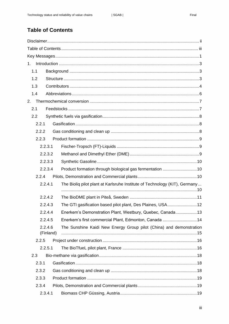
2.2.4.2 The BioDME plant in Piteå, Sweden
The key technologies in the BioDME plant are:
Chemrec Black Liquor (BL) gasification technology operating at close to 3.0 MPa.
HaldorTopsoe syngas to methanol and DME technology.
Today the plant is owned and operation by LTU. The gasification plant was started in
September 2005 and the Bio-DME unit in November 2011. The feedstock is sulphate (Kraft)
BL from the neighbouring sulphate mill but also sulphite liquor has also been successfully
tested.
The synthesis plant downstream the gasifier has also been used for testing an innovative,
once-through syngas to methanol conversion technology.
Recently BL has been mixed and co-gasified with Pyrolysis Oil (PO) to augment syngas
generation capacity for a certain BL, i.e. pulp output, capacity. Syngas generation can increase
100% - 200% via pyrolysis oil addition. Pyrolysis oil is converted to syngas with about 85%
marginal efficiency when gasified in combination with BL which makes this type of co-
gasification a very efficient way to upgrade pyrolysis oil energy.

Technology status and reliability of value chains | SGAB | Final
12
Plant Type P/D/C
Start-up year
Feedstock capacity Product By-product
MW
Hours in operation
Chemrec gasifier
P 2005 3MW
(20 tonnes dry BL per day)
1.8MW -- >27,000
BioDME P 2011 4 tonnes DME/d
-- ~11,000
The plant has been operated in periods of 2 to 3 weeks with a yearly uptime in the order
of 40%-60% of the calendar time.
In construction of a BL gasification to fuels plant the gasification technology is the only
innovative part of the facility. The downstream parts are already commercially proven. In the
BioDME plant however HaldorTopsoe decided to test their novel so called CONRAD methanol
technology upstream of the commercial methanol to DME conversion unit.
In 2010-2012 the Domsjö Mill in Örnsköldsvik planned to change out their old sulphite
recovery boilers to Chemrec gasification technology converting its liquor to methanol at a
capacity of 180 MW liquor to be gasified in two gasifiers plus one spare gasifier. The Swedish
government awarded a 55 million EUR (€) grant for the investment and the project was
approved from the Directorate General Competition in Brussels, but Sweden lacked the long
term biofuel market policy which was necessary to make financing possible. The project was
therefore stopped and the grant received from the Swedish Government as investment support
was not used. The pulp mill is still in need of a new chemical recovery unit (have two more
than 50-year-old recovery boilers) and the project may thus be reopened.
2.2.4.3 The GTI gasification based pilot plant, Des Plaines, USA
The key technologies in the biomass to synthetic gasoline plant are:
U-Gas based Carbona steam/oxygen gasification technology already in place at GTI.
HaldorTopsoe catalytic syngas cleanup
HaldorTopsoe Tigas process to produce gasoline from generated syngas
Plant Type P/D/C
Start-up year
Feedstock capacity
Product By-product
MW
Hours in operation
Carbona/HTAS/GTI D 2012 19.2 tonnes/d 3 tonnes/d -- 3,000
The plant has been operated in several test campaigns at elevated pressure, and some
30 tons of gasoline was produced for car fleet testing. The totally automatic process operation
was smooth and reliable. The product is 89-92 Research Octane Number (RON) gasoline. The
quality of the product has been approved by USA officials to be directly blended with
conventional gasoline in the USA. The process is claimed to be technically ready for scale-up
to commercial plant size.

Technology status and reliability of value chains | SGAB | Final
13
The GTI gasification plant , Des Plaines, USA Enerkem Demonstration Plant, Westbury, Quebec, Canada
2.2.4.4 Enerkem’s Demonstration Plant, Westbury, Quebec, Canada
Enerkem’s demonstration facility in Westbury, Quebec, employ’s Enerkem’s in-house
technology to convert waste wood (decommissioned telephone poles) and post-sorted
municipal solid waste to methanol and ethanol. The technology was scale-up from its pilot
facility which had accumulated 4,500 hours of operation. Key technologies are:
Gasification technology: Bubbling fluidized bed operating at low pressure (0.2MPa-
0.4MPa)
Gas cleaning technology: wet scrubbing and absorber/stripper system developed by
Enerkem
Synthesis technology: Syngas to methanol and ethanol catalytic synthesis process
developed by Enerkem
Conditioned syngas production began in 2009, methanol production in 2011 and ethanol
production in 2012.
Plant Type P/D/C
Start-up year
Feedstock capacity Product By-product
MW
Hours in operation
Enerkem D 2009 48 tonnes (dry basis
bone)/d 11 (ethanol) tonnes/day
12,800
The Westbury demonstration plant has been used by Enerkem to develop its commercial
plant design. Technical issues that needed optimisation were feedstock feeding, feedstock
gasification, syngas clean-up and catalytic synthesis and these have been overcome, tested
and demonstrated in this facility before designing Enerkem’s commercial plants.
Successful demonstration of MSW-to-methanol and ethanol in this plant since 2009 was
followed by the deployment of Enerkem’s technology at commercial scale at its Edmonton
plant.

Technology status and reliability of value chains | SGAB | Final
14
2.2.4.5 Enerkem’s first commercial Plant, Edmonton, Canada
The key technologies in the Enerkem Edmonton plant have been developed by Enerkem
Inc. and have been tested at demonstration scale as described above. The Edmonton plant
comprises the same process technology.
The plant converts post-sorted municipal solid waste (fraction remaining after separation
for recycling and composting) to methanol and ethanol. The plant is located on the site of the
City of Edmonton’s integrated waste management center, and will help the city increase its
waste recycling rate to 90%.
Plant Type P/D/C
Start-up year Feedstock capacity
Product By-product
MW Hours in operation
Enerkem C 2015 300
tonnes/d 88 (ethanol) tonnes/day
---
Accumulated 2,594 hours during
production ramp-up (as of fall 2016)
The plant was commissioned for methanol production and completed a performance test
producing methanol in summer 2015 with an uptime of 60% over the last month of operation
before a planned shut-down to expand the production capacity. The plant has resumed
operations for methanol production in April 2016 and has produced about 240 tonnes as of the
first week of May. The methanol being produced since April 2016 meets IMPCA (International
Methanol Producers & Consumers Association) specifications. The facility has also received
the ISCC (International Sustainability & Carbon Certification) one of the approved EU
certification schemes for the production of its methanol to be also sold as a biofuel under the
2009/28/EC Renewable Energy Directive (RED). A methanol to ethanol conversion module is
being added in 2016 and will be ready for start-up in 2017. Ethanol is expected to be the
primary product. The plant is currently producing and selling increasing volumes of bio-
methanol and no technology barriers have been identified.
Enerkem Plant in Edmonton, Canada Illustration of Enerkem’s VANERCO project, Canada
Enerkem is planning a plant, the VANERCO plant, in Varennes, Canada utilizing the same
technology as in previous plants. The plant will convert waste from the Industrial, Commercial

Technology status and reliability of value chains | SGAB | Final
15
and Institutional sector, urban waste as well as construction and demolition debris to methanol
and ethanol. Construction is expected to start in 2017.
Plant Type P/D/C
Start-up year
Feedstock capacity
Product By-
product MW
Hours in operation
Enerkem C 2019 300 tonnes/d
(dry)
99 tonnes/day (ethanol) or
142 tonnes/day (methanol)
---- Project in
development
A major Dutch partnership including AkzoNobel, Enerkem and other partners aim to
develop a plant in the Netherlands using Enerkem's conversion technology to manufacture
synthesis gas from domestic and other waste and use it as a feedstock for making products
such as methanol and ammonia.
2.2.4.6 The Sunshine Kaidi New Energy Group pilot (China) and demonstration
(Finland)
The FT diesel and naphta demonstration plant project is planned to be constructed by
Sunshine Kaidi (Finland) New Energy Co. Ltd, owned by Chinese company Sunshine Kaidi
New Energy Group. The group has in-house technology for the key processes. A pilot plant
has been operated since 2013 in Wuhan, China. The plant has an AlterNRG gasifier and a
fixed bed cobalt based FT process (technologies owned by Kaidi). Pilot plant data and
operations are confidential.
Plant Type P/D/C
Start-up year
Feedstock capacity
Product By-
product MW
Hours in operation
Pilot plant, Wuhan, China
P 2013 -- -- -- --
Reference plant, Ajos, Kemi, Finland
D/C 2019 ~800 MW
500 tonnes/d FT diesel
167 tonnes/d bio-naphtha
-- Project in
development
The next step is to implement a full-scale demonstration plant. The raw material will be
forest residues. The plant in Finland will include the following units:
Biomass receiving and drying to about 85% dryness
Plasma gasification technology (in-house technology and catalysts) at atmospheric
pressure to produce tar-free syngas
Cleaning and conditioning of syngas
Gas-to-liquid conversion by Fischer-Tropsch synthesis
Refining the FT- intermediate products to the final products

Technology status and reliability of value chains | SGAB | Final
16
Utilities
The separate process units represent either proven technology in commercial scale or
demonstrated in pilot plant scale. Combination of the units using wood as raw material is new
in commercial scale. In the reference plant further optimizing and improvements will be made.
The main target is to still improve the greenhouse gas savings, although the basic
requirements of the RED will be met.
Kaidi’s New Energy Group pilot, China
2.2.5 Project under construction
2.2.5.1 The BioTfueL pilot plant, France
The key technologies used in the BioTfueL plant are
ThyssenKrupp POLTORR double-zone-MHF (Multiple Hearth Furnace) torrefaction
system
ThyssenKrupp PRENFLO PDQ (Pressurized Direct Quench) Technology
Axens GASEL® Technology
Plant Type P/D/C
Start-up year
Feedstock capacity
Product
By-product MW
Hours in operation
BioTfueL P 2016 15 MW -- -- ---
The aim of the project is to develop, built and operate two demonstration plants in order to
develop and market a complete BtL-XtL process for the conversion of biomass in high quality
Jet Fuel and Diesel. The BioTfuel plant will be able to gasify and convert 100% of biomass as
well as biomass/petroleum coke and biomass/coal mixtures to be fully independent of potential
seasonal feedstock restrictions and/or customer economical feedstock needs. The nameplate
capacity of the PRENFLO PDQ Gasifier operating under 3.0MPa-3.5MPa bar is 15MWth. The
commissioning of the two demonstration plants (Torrefaction unit in Venette and grinding,
gasification, gas treatment and a sub-pilot FT Test Unit in Dunkirk) will start end of 2016. The
test program will start in 2017 and will be executed for three years.

Technology status and reliability of value chains | SGAB | Final
17
BioTfueL pilot plant (torrefaction unit), France BioTfueL pilot plant (main unit), France

Technology status and reliability of value chains | SGAB | Final
18
2.3 Bio-methane via gasification
2.3.1 Gasification
Methane formation is favoured by low gasification temperature and therefore gasifiers
operating at low temperatures are preferred. For further description of the gasification step see
section 2.2.
This favours bubbling and
circulating bed gasifiers that are
operated at lower temperatures
(800°C-950 C) for this conversion
route.
The raw gas mainly consists of
H2, CO, CH4 and tar components.
The gas is comparably rich in
methane and contributes typically
with about one third of the energy
content of the raw gas from the
gasifier. The non-combustible
components are inert gases and
particulate matters.
The energy needed to carry out
the gasification reactions can either
come from partial combustion of
the processed material in the
gasification stage as described
above or allothermally, i.e.
indirectly via heat exchangers or
via a circulating, solid heat
transferring medium (i.e.,
combustion and gasification are physically separated). In the latter case the heat may be
generated by combustion of the non-gasified part of the feedstock material, char, internally
produced wastes and product gas or from external fuel sources in air. These so-called indirect
type of gasifiers therefore do not require oxygen to produce the syngas. They are on the other
hand difficult to pressurize.
2.3.2 Gas conditioning and clean up
Impurities of the raw gas depend on the gasification condition and biomass used and can
cause corrosion, erosion, deposits and poisoning of catalysts. It is therefore necessary to clean
the raw gas. Depending on technology impurities such as dust, ashes, bed material, tars and
alkali and chloride compounds are removed through various cleaning steps, either at
temperature by catalytic reforming of tar or at low temperature by specific scrubbing media
(e.g. biodiesel). Components having mainly poisonous effects on the catalysts are sulphur and
chloride compounds.
The (partly) cleaned raw gas will be conditioned before further processing to methane can
be carried out. The desired H2/CO ratio of 3.0 is obtained by the water-gas shift reaction. This
Figure 2.2 Bio-methane via Gasification

Technology status and reliability of value chains | SGAB | Final
19
adjustment can be carried out upstream of the methanation, or, as a part of the methanation
process, if suitable catalysts and higher temperature of operation is used.
The CO2 and sulphur component in the gas needs to be removed. This is normally done
by a physical or chemical absorption process. Sulphur components can either be removed
before or after the water-gas shift reaction but before the methanation step which follows.
The removal of CO2 can be performed by various types of commercially available
technologies. Type of technology is mainly dependent on plant size. Some concepts have a
CO2 removal also upstream the shift unit but regardless if that is the case a final CO2 removal
step is required downstream of the methanation
2.3.3 Product formation
Biomethane production requires methanation of the cleaned syngas, followed by a (final)
CO2 removal. In the methanation step (catalysed by Nickel Oxide at 2.0MPa-3.0MPa pressure
and order of 400°C temperature) carbon monoxide reacts with hydrogen forming methane and
water.
The conversion is very exothermic and very selective. As both CO and H2 are undesired
components in natural gas, the process is driven to high CO conversion by extensive
recirculation.
2.3.4 Pilots, Demonstration and Commercial plants
2.3.4.1 Biomass CHP Güssing, Austria
(owned by Güssing Energy Technologies (GET) with Technikum Güssing, operated by Bioenergy2020+ and the
Technical University Vienna)
The plant is a CHP (Combined Heat & Power) facility (gasification at atmospheric pressure
combined with a gas engine) but it has during periods been test site for gas conversion
technologies where a slip stream from the plant has been used as feed stream for a Bio-SNG
(Synthetic Natural Gas) pilot (1MW capacity), two FT diesel pilots (5kg/day and 1 barrel per
day (bpd) respectively), a pilot for production of higher alcohols (1-2 liters/day) and a pilot for
hydrogen production (3 Nm3/day).
Plant Type P/D/C
Start-up year
Feedstock capacity
Product
By-product MW
Hours in operation
Güssing C 2002 8-10MW 2.0MWel 4.5MWth
--- >80,000
The Güssing concept has been duplicated in several places for CHP applications by
Repotec, Ortner Anlagenbau and also lately by GREG. After construction and start up of a
couple of plants in the same approximate size as the Güssing plant the technology was scaled
up about 4 times and implemented in Gothenburg, Sweden.

Technology status and reliability of value chains | SGAB | Final
20
Biomass CHP Güssing, Austria GoBiGas plant in Gothenburg, Sweden
2.3.4.2 The GoBiGas plant in Gothenburg, Sweden
The gasification technology implemented in the GoBiGas plant is a four times scale up
from the original plant in Güssing, Austria (see above) done by Valmet under a license from
Repotec. The GoBiGas plant furthermore includes tar removal via scrubbing and active carbon
filters. Water gas shift and methanation units have been provided by Haldor Topsöe A/S. The
plant also includes acid gas removal technology.
Plant Type P/D/C
Start-up year Feedstock capacity Product By-product
MW
Hours in operation by
Dec 2015
GoBiGas D 2013
6.8 tonnes/h (pellets, 5.5% moisture)
8.9 tonnes/h (Forest residue, 20%
moisture)
20 MW Distr. heat
Gasifier 6,400h
Methanation 2,100h
The plant first delivered Bio-SNG (Synthetic Natural Gas) to the grid in December 2014
and has until December 2015 supplied 30GWh, mainly during the latter part of 2015. The plant
has also delivered 25GWh district heat to the Gothenburg district heating network.
The plant is currently shifting feedstock from wood pellets to forest residues.
At start up the plant encountered problems with too a high formation of tars. This was
resolved via adding small quantities of alkali salts to the feedstock. The active carbon filter
beds have been limiting when reaching full production and a smaller revamp of the unit is under
way.
However, and in spite of that the GoBiGas phase1 plant is now in its initial operation, the
plan for investment in GoBiGas 2 at a scale of 100MW biomethane product has been stopped
by the city council.
2.3.4.3 The “Gogreengas” Pilot Plant, Swindon, UK
The Gogreengas pilot plant is a development facility for proving and optimizing the process
for manufacturing Bio-SNG from Refuse Derived Fuel (RDF) and biomass feedstocks. The

Technology status and reliability of value chains | SGAB | Final
21
project is a partnership between National Grid Gas Distribution, Advanced Plasma Power
(APP), Progressive Energy and Carbotech (a subsidiary of Viessmann).
The funding and strategic backing for the project comes from the UK energy regulator
Ofgem’s Network Innovation Competition, the European BioEnergy Securing the Future
ERANET programme and the project partners.
Dried RDF and other feedstocks are converted to syngas in a two stage gasification
process using APP’s Gasplasma® technology (fluidized bed gasifier at atmospheric pressure
designed by Outokompou Energy, close-coupled with a plasma converter). The plasma stage
removes tars leaving a syngas which is predominantly CO and H2 and is also used to vitrify
the ash. After further conventional gas processing, the syngas undergoes a water gas shift to
adjust the proportions of the CO and H2, followed by catalytic methanation. The arising CO2 is
removed from the methane using a pressure swing absorption unit to produce pipeline / vehicle
quality Bio-SNG.
The design incorporates provisions to evaluate a number of reactor configurations and a
variety of catalyst bed geometries during the testing period.
Plant Type P/D/C
Start-up year
Feedstock capacity
Product By-product
MW
Hours in operation
Gogreengas P 2016 0.4 tonnes/d 0.050MW - n/a
The plant has been commissioned and initial experimental work undertaken using test
gases. End-to-end operation is about to commence, initially at low dilutions, and the plant will
be progressively brought on stream and optimized during the remainder of 2016.
The process challenges include the removal of heat in the highly exothermic methanation
reactions given the smaller scale than conventional fossil plants, and the production of a
substitute natural gas that meets the stringent regulations for gas grid injection.
The project partners have commenced construction of a commercial Bio-SNG facility on
the same site that will process 900kg/h of dry RDF to produce 3MWth of pipeline / vehicle
quality Bio-SNG under commercial contracts. The plant will be operational by the end of 2017,
enabling wider commercial deployment.
The “Gogreengas” Pilot Plant, Swindon, UK

Technology status and reliability of value chains | SGAB | Final
22
2.4 Production and upgrading of pyrolysis products and lignin rich
fractions
2.4.1 Pyrolysis
Pyrolysis is the chemical decomposition of organic matter by heating in the absence of
oxygen. The biomass decomposes into vapour including steam, aerosols, and char; the
proportions of these three states depend on temperature and duration of the pyrolysis. Two
alternatives are thermal and catalytic
pyrolysis.
The decomposition which mostly
results in a liquid fraction is of
particular interest as the liquid is
transportable and storable. The
highest yield of liquid fraction is
obtained by thermal fast pyrolysis.
This type of technology opens up for a
concept where the intermediate
product, the pyrolysis oil, is produced
locally and upgrading of the oil is done
in large plants fed by products from a
large number of pyrolysis oil plants.
Fast pyrolysis takes place in order
of seconds at around 500 C. In
preparation, the biomass needs to be
dried to typically less than 10% water
and crushed/milled to particles of less
than 5mm. The heating medium is
typically sand, but also catalysts have
been used. The biomass decomposes into organic vapours, non-condensable gases, pyrolysis
water, and char. When the gaseous components cool down and condense, a dark brown
viscous liquid is formed from the organics and the water, which is called fast pyrolysis oil or
sometimes bio-oil. The use of the word “oil” implies that its characteristics are similar to
conventional crude oil based products. However, this is not the case, the oxygen content is as
high as for biomass, it is acidic, and the bio-oil cannot under normal circumstances be mixed
with or dissolved in either conventional oil or with water.
Pyrolysis Oil is obtained in yields of up to 65%wt on dry feed basis. The by-products char
and gas are used within the process to provide the process heat requirements plus possibly
also extra energy for export. Pyrolysis oil has a heating value about half that of conventional
fuel oil and typically also has some ash. It is currently commercially used in CHP stand-alone
applications or replacing fossil fuels. For this purpose, the product has been certified for EU
Figure 2.3 Production and upgrading of pyrolysis products and lignin-rich fraction

Technology status and reliability of value chains | SGAB | Final
23
Regulation for Registration, Evaluation, Authorisation and Restriction of Chemicals (REACH3)
and has an American Society for Testing and Materials (ASTM) specification for use as
renewable fuel oil while the European Committee for Standardization (CEN) develops
standards for wider applications.
A different quality pyrolysis oil is generated in catalytic pyrolysis, where catalyst is used as
heating media instead of sand. The oil has typically a lower oxygen content at the expense of
a lower mass and energy yield.
2.4.2 New technology developments – Upgrading/Co-processing of pyrolysis oil
and other lignin rich fractions
2.4.2.1 Via pyrolysis oil and torrefaction
There are on-going developments for pyrolysis oil to be upgraded and co-fed in existing
refineries The mixed bio-fossil products will have the same combustion properties as
conventional fossil transport fuels.
The following summarizes various routes possible to upgrade virgin biomass to different
types of fuels. Technology developers have been working in all of these areas for the past 10
- 20 years. Technology developers have built several plants at pilot (P)/ demo (D) stage. The
commercialization of these processes will depend on how effective they are for finding
solutions to catalyst lifetime in the different parts of the process and how compatible the
intermediates are with fossil fractions and processing.
Fast pyrolysis → gasification or co-gasification with e.g. black liquor → synthesis to biofuel
product (KIT, LTU).
Fast pyrolysis → (stabilization) → co-feed to refinery Fluid Catalytic Cracking (FCC) (UOP,
PetroBras; Repsol, Grace) – see below.
Fast pyrolysis → stabilization → Hydrodexygenation and Hydrocracking (BTG Biomass
Technology Group BV (BTG), US Department of Energy - Pacific Northwest National
Laboratory (PNNL)).
Catalytic pyrolysis → Hydrodexygenation and Hydrocracking (Anellotech, Center for
Research & Technology Hellas (CERTH)).
Hydropyrolysis (hydrogen + catalysts) → Hydrodesulphurization + Dearomatization (Gas
Technology Institute (GTI)/ CRI Catalyst Company (CRI)).
Product qualities vary considerably: Fast pyrolysis liquids have low quality due to their high
content of water (~25%wt) an acid (3.0-4.0%wt) as well as inherent instability; Catalytic
pyrolysis liquids have a water content of 5 -6%wt and are stable; Hydropyrolysis liquids contain
no water.
In FCC co-processing, the pyrolysis oil is transported to a refinery where it is co-processed
in its FCC unit. Typically, a few percent of pyrolysis oil will be added to current petroleum based
3 Regulation (EC) No 1907/2006 of the European Parliament and of the Council of 18 December 2006 concerning the Registration, Evaluation, Authorization and Restriction of Chemicals (REACH).

Technology status and reliability of value chains | SGAB | Final
24
feed to the FCC unit. In the FCC process the larger molecules will be broken down to fuel-type
carbon lengths using elevated temperature and presence of a cracking catalyst. Also
deoxygenation of the pyrolysis oil will take place to produce CO2, CO, soot and water. The
product streams from the FCC process will, as a result, contain a percentage of renewable,
cellulosic feedstock derived fuel. As the level of modifications required to the FCC unit are
limited, the capital requirement to implement FCC co-processing is relatively low. The
described concept has been developed by UOP in their laboratories. The concept was
thereafter verified during 2013 in an oil refinery in the Chicago area.
Pyrolysis oil has also been gasified and co-gasified with black liquor from the pulping
process with very good results, see section 2.2.4.
The other methods referred to above are being developed in laboratory and pilot scale.
2.4.2.2 Via fraction of lignin
Lignin from pulping processes or from fermentation of lignocellulosic materials can be used
as an intermediate for the production of biofuels.
Lignin is a polymeric substance composed of phenolic monomers and is one of the main
components of wood and grasses after cellulose and hemi-cellulose. After pulping it is found
dissolved in the pulping liquor. In the case of ethanol production by other means than by
chemical pulping, it is found as a solid after the pre-treatment or after fermentation depending
on the process configuration.
The processing of the lignin is by first, de-polymerization to mono- and oligomers. This can
be done on the dissolved material in a liquor or by extracting lignin and as a solid or re-dissolve
it. The oligomeric and monomeric substances are then separated and hydro-treated to produce
aromatic and cyclical hydrocarbons.
Mossi & Ghisolfi (M&G) of Italy is investigating if the lignin fraction being a by-product from
their second generation ethanol plant can be upgraded using fermentation pathways. The
project is called BIOREFLY. The research goals of the project are linked to the construction
and operation of a pilot plant based on second generation technology. The goal of the
BIOREFLY project is the construction of a 2,000 tonnes/y bio jet fuel plant. It will use lignin
cake obtained from the conversion of both dedicated energy crops and agricultural residues in
the second generation bioethanol production biorefinery in Italy.
In Sweden, lignin separated from black liquor is processed in a similar type of process, and
pilot scale units are being implemented.
2.4.3 Pilots (P), Demonstration (D) and Commercial (C) plants
2.4.3.1 The Bioliq plant at KIT, Germany
The Bioliq plant at KIT has a pyrolysis step as pretreatment of the feedstock (straw)
upstream the gasification plant. See chapter 2.2.4
2.4.3.2 The Fortum plant in Joensuu, Finland
The pyrolysis technology used in the Fortum plant extracts a part stream from bed material
circulation loop from a biomass fuelled Circulated Fluidized Bed (CFB) boiler and feeds it to
the pyrolysis reactor. Downstream of the pyrolysis unit, the vapours are separated and

Technology status and reliability of value chains | SGAB | Final
25
condensed while the sand, the char and the remaining gases are returned to the boiler. The
by-products (char and uncondensed gases) are fully utilized by re-feeding them as fuel to the
CFB boiler.
Plant Type P/D/C
Start-up year
Feedstock capacity
Product By-product
MW
Hours in operation
Fortum C 2013 50 MW 30MW Not reported
The plant has been operated as a demonstration unit, using different kind of raw materials
and production parameters in order to develop and optimize the process. Final product has
been used for replacing Heavy Fuel Oil (HFO) and tested with several sizes of boilers, from
1MW to 300MW.
Fortum has two similar projects in NER 3004 (New Entrants’ Reserve) in two different Baltic
states. These plans are to expand the production and end-user concepts to new customers
and markets, including further development of the oil quality and processes in order to generate
higher valued products such as transportation fuels.
Fortum‘s plant in Joensuu, Finland Empyro’s plan, Hengelo, Holland
2.4.3.3 The Empyro plant, Hengelo, Holland
The Empyro plant utilizes the BTG-BtL pyrolysis process in which the rotating cone reactor
is integrated in a circulating sand system composed of a riser, a fluidized bed char combustor,
the pyrolysis reactor, and a down-comer. In this concept, char is burned with air to provide the
heat required for the pyrolysis process. Oil is the main product; non-condensable pyrolysis
4 NER 300 is so called because it is funded from the sale of 300 million emission allowances from the New Entrants’ Reserve (NER) set up for the third phase of the EU Emissions Trading System (EU ETS).

Technology status and reliability of value chains | SGAB | Final
26
gases are combusted and are used to generate additional steam and power. Excess heat is
used for drying the feedstock.
Plant Type P/D/C
Start-up year Feedstock capacity
Product By-product Hours in operation
Empyro D/C 2015 120 tonnes/d (clean wood
residues)
77 tonnes/d (crude pyrolysis oil) 8MW
>3,500 by
31/8/2016
The Empyro plant design is based on experiences from the BTG pilot plant. This plant has
the following overall data.
Plant Type P/D/C
Start-up year Feedstock capacity
Product By-product
MW
Hours in operation
BTG P 1998 5 tonnes/d 3 tonnes/d (crude pyrolysis oil) - > 2,000*
* Intermittent operation only (was not designed for continuous operation)
BTG-BtL is involved in up-grading of the co-processing of crude pyrolysis oil in existing
refineries (primarily co-FCC) and/or upgrading processes from crude pyrolysis oil to advanced
biofuels. Development of the right catalysts for upgrading of crude pyrolysis oil to advanced
biofuel is a key task. The company is also developing its technology to enable commercial
production of crude pyrolysis oil from agricultural non-food residues.
2.4.3.4 ENSYN plant in Renfrew, Canada
The key technology used in the Renfrew plant is ENSYN Rapid Thermal Processing (RTP)
technology. RTP™, converts non-food biomass from the forest and agricultural sectors to
liquids through fast pyrolysis. The residence time in this unit operating at 520°C is 1-2sec
(typical for fast pyrolysis), where after the product vapours are condensed using quenching by
cold pyrolysis liquid.
Plant Type P/D/C
Start-up year Feedstock capacity
Product By-product
MW
Hours in operation
Renfrew D 2006,
improved 2015 70 tonnes/d
>20,000 tonnes/yr (depending on
feedstock) --- Not given
The plant produces a Renewable Fuel Oil (RFO), a petroleum-replacement to be used for
heating purposes.
There are more than 10 plants utilizing the RTP technology in operation. ENSYN has
formed a joint venture with Honeywell UOP called Envergent. One task for the new company
is to develop a process which makes it possible to combine fast pyrolysis of biomass

Technology status and reliability of value chains | SGAB | Final
27
feedstocks with upgrading of the product to a degree which makes it possible to combine
pyrolysis technology with crude oil refining in existing oil refineries. See chapter 2.4.2.
ENSYN’s plant in Renfrew, Canada
2.5 Upgrading of a wide variety of wastes and residues to
Hydrotreated Vegetable Oils (HVO)
HVO can be produced from a wide
variety of materials containing
triglycerides and fatty acids.
Within this range of materials, HVO is
flexible in its feedstock requirements
allowing the use of a wide range of low
quality waste and residue materials still
leading to production of hydrocarbon
drop-in products.
The block diagram illustrates the key
process steps leading form the fatty acid
containing feedstocks to renewable
hydrocarbon products suitable for
blending into the refinery product slate.
The key additional feedstock needed is
hydrogen which today comes from a fossil
source.
HVO type of biofuels can be
produced by either investing in stand-
alone facilities or by converting the
existing oil refineries into HVO technology production or co-production facilities.
2.5.1 HVO Stand-alone production facilities
Currently, 3.5 million tonnes/yr of HVO production takes place globally expected to
increase to 6-7 million tonnes/yr by 2020. In the EU, further refinery conversions and co-
Figure 2.4 Upgrading of waste and residues to Hydrotreated Vegetable Oils (HVO)

Technology status and reliability of value chains | SGAB | Final
28
processing have the potential to provide additional biofuel volumes in the range of 12 million
tonnes/yr on top of that.
Neste was the first to invest in an HVO refinery (Porvoo 2007). Currently, Neste has a
production capacity of 2.4 million tonnes/yr, with stand-alone refineries in Porvoo (Finland),
Singapore and Rotterdam (the Netherlands).
In the US, Diamond Green operates a HVO stand-alone facility of 430 thousand tonnes/yr,
and in Finland, UPM operates since 2015 their HVO refinery of the capacity of 100 thousand
tonnes/yr. In addition, in the US, Renewable Energy Group has a (currently idle) HVO facility
of 225 thousand tonnes/yr, and Emerald Biofuels plans to invest in a facility of 250 thousand
tonnes/yr in 2018.
2.5.2 HVO production through refinery conversion
There is a large number of traditional oil refineries in the EU with refinery technology
suitable for HVO conversion, as they have two hydrotreaters which were originally designed
for removal of sulphur and nitrogen from fossil feeds by hydrogen treatment. Already ENI S.P.A
(ENI) has converted their Venice refinery to 0.3 million tonnes/yr of HVO, and a refinery in
California has been converted by Altair to 0.2million tonnes/yr output. A second ENI refinery,
Gela in Sicily is being converted to 0.5million tonnes/yr product, as is the Total refinery at La
Mede, France.
Additional refinery conversions may take place in the future as soon as the market
conditions look more favourable for renewable fuels than fossils.
2.5.3 Co-processing
In addition to the 100% HVO production, biofuels can be produced through co-processing.
In co-processing, biomaterial is fed into refinery units together with fossil feeds typically in low
(<5%wt-10%wt) blends, but higher blends are in use by e.g. Preem in Sweden. As the refinery
processes are complex and units interlinked, co-processing bio-feeds in integrated refinery
lines results in fractionation of bio-components in multiple products streams.
Co-processing already takes place in the EU, but detailed information about co-processed
bio-volumes are not publicly available. A rough estimation of the volume potential of co-
processed biofuels could be that if 30% of EU refining capacity (230 million tonnes/yr) would
use 5% bio-feed, the resulting biofuel volume would be in the range of 3.5 million tonnes/yr.
At least Preem in Sweden has production of 200,000 tonnes/yr through co-processing, and
Repsol and Cepsa in Spain are estimated to produce co-processed biofuels in the scale of
approx. 60,000 tonnes/yr each while ConocoPhillips is also co-processing in Cork, Eire.
2.5.4 Pilots, Demonstrations and Commercial Plants
2.5.4.1 Neste
Neste has developed its own technology for HVO processing in cooperation with a catalyst
partner and commercialized this under the name of Neste Renewable Diesel (produced with
Neste's NEXBTL technology). Neste is by far the largest producer on the market at present
and controls around two third of the world production capacity.

Technology status and reliability of value chains | SGAB | Final
29
Plant Type P/D/C
Start-up year
Feedstock Product By-product
MW Hours in operation
Porvoo, Finland
C 2007
Various Vegetable Oils and waste
streams
200,000 tonnes/yr
-
commercial operation
since start-up
C 2009 200,000 tonnes/yr
-
commercial operation
since start-up
Singapore
C 2010 1,000,000 tonnes/yr
-
commercial operation
since start-up
Rotterdam, The Netherlands
C 2011 1,000,000 tonnes/yr
-
commercial operation
since start-up
Neste’s HVO plant, Rotterdam, The Netherlands
2.5.4.2 UPM’s Lappeenranta Biorefinery plant, in Lappeenranta, Finland
The UPM Lappeenranta biorefinery, producing wood-based renewable diesel from forestry
residue (crude tall oil), started commercial production in January 2015. The biorefinery, located
on the same site as the UPM Kaukas pulp and paper mill, has proven its technological and
commercial capability. UPM has publicly announced that the biorefinery reached profitable
results already at the end of 2015. Total investment: 175 million EUR.
The key technology used in the Lappeenranta biorefinery is hydro-treatment provided by
Haldor Topsoe.
Plant Type P/D/C
Start-up year Feedstock capacity
Product By-product
MW Hours in operation
Lappeenranta biorefinery
C 2015 Crude tall oil
(capacity confidential)
100,000 tonnes/yr (120 million litre/yr)
-- ~10,000

Technology status and reliability of value chains | SGAB | Final
30
The plant has run very reliable with the longest run being over several months. There are
no technical barriers encountered so far.
Crude tall oil is a natural extract of wood, mainly from conifers. Crude tall oil is gained as a
result of the separation process of fibrous material from wood. It is a residue of pulp
manufacturing. Crude Tall Oil is part of Annex IX, part A and therefore classified by the
European institutions as residue and eligible for double-counting and is part of the sub-target
for advanced biofuels. In Lappeenranta, a significant part of this renewable raw material comes
from UPM’s own pulp mills in Finland – like the Kaukas mill site next door.
UPM’s Lappeenranta Biorefinery plant, Lappeenranta, Finland
Diamond Green Diesel, Louisiana (USA)
2.5.4.3 Diamond Green Diesel, Louisiana (USA)
The plant is a joint venture between Darling Ingredients Inc. and Valero. Darling is
specializing in production of specialty ingredients from animal origin for applications in the food,
feed and fuel industries. Valero is the largest independent petroleum refiner and marketer in
North America. The plant utilizes the Ecofining™ process from UOP to convert feedstocks like
vegetable oils, animal fats and greases to “drop in” hydrocarbon fuels via deoxygenation,
isomerization and product separation.
The plant is co-located next to a petroleum refinery to leverage existing assets and to
minimize capital cost. Capacity is planned to be increased to 18,000 barrel/day.
Plant Type P/D/C
Start-up year Feedstock capacity
Product By-product
MW Hours in operation
Diamond Green Diesel
C 2013
Expansion in 2016 10,000
barrel/day Confidential Confidential
Continuous Since 2013
2.5.4.4 Eni’s Green Refinery Project, Venice, Italy
The plant utilizes the Ecofining™ process from UOP to convert feedstocks like vegetable
oils, animal fats and greases to “drop in” hydrocarbon fuels via deoxygenation, isomerization
and product separation The project involves the conversion of an existing oil refinery into a
biorefinery by a revamp of two existing hydrotreating units. Hydrogen is provided by the
existing catalytic reforming unit.
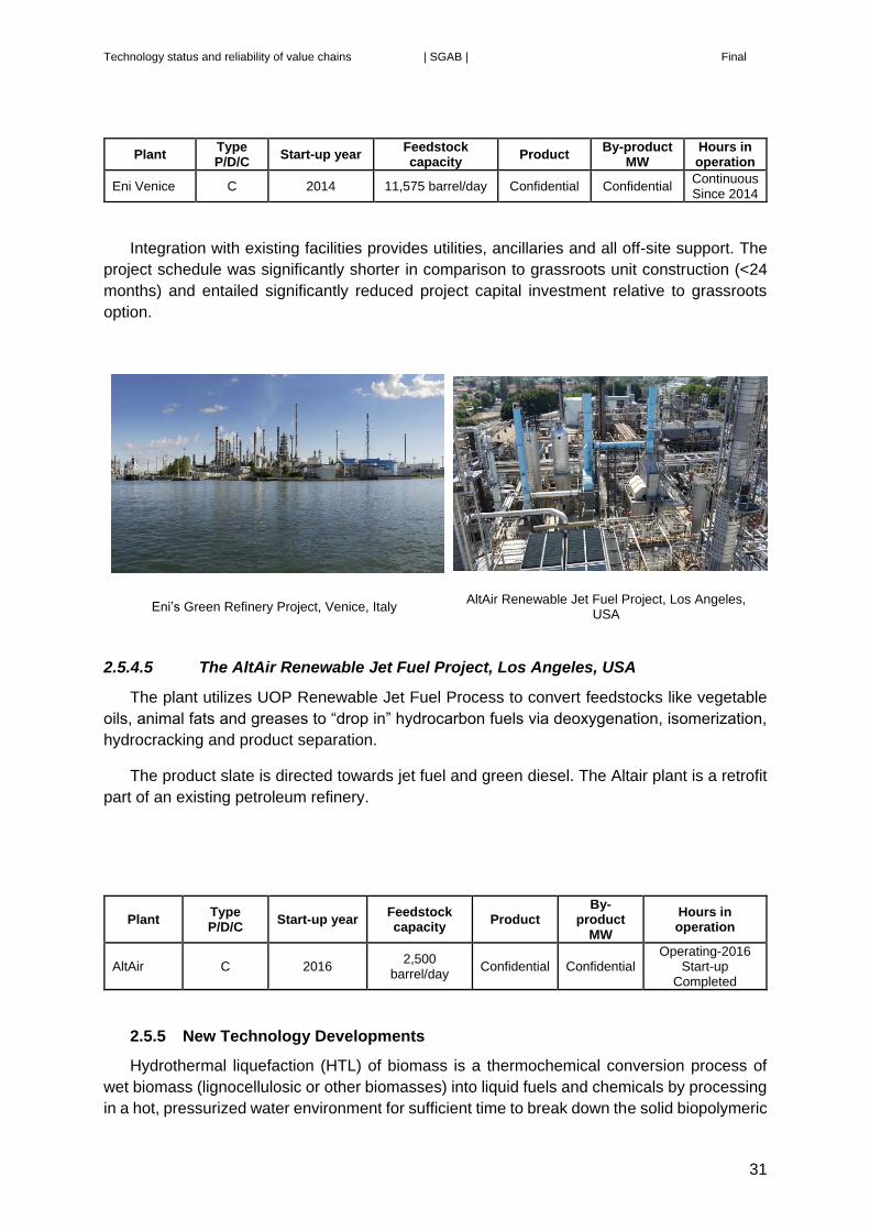
Technology status and reliability of value chains | SGAB | Final
31
Plant Type P/D/C
Start-up year Feedstock capacity
Product By-product
MW Hours in operation
Eni Venice C 2014 11,575 barrel/day Confidential Confidential Continuous Since 2014
Integration with existing facilities provides utilities, ancillaries and all off-site support. The
project schedule was significantly shorter in comparison to grassroots unit construction (<24
months) and entailed significantly reduced project capital investment relative to grassroots
option.
Eni’s Green Refinery Project, Venice, Italy AltAir Renewable Jet Fuel Project, Los Angeles,
USA
2.5.4.5 The AltAir Renewable Jet Fuel Project, Los Angeles, USA
The plant utilizes UOP Renewable Jet Fuel Process to convert feedstocks like vegetable
oils, animal fats and greases to “drop in” hydrocarbon fuels via deoxygenation, isomerization,
hydrocracking and product separation.
The product slate is directed towards jet fuel and green diesel. The Altair plant is a retrofit
part of an existing petroleum refinery.
Plant Type P/D/C
Start-up year Feedstock capacity
Product By-
product MW
Hours in operation
AltAir C 2016 2,500
barrel/day Confidential Confidential
Operating-2016 Start-up
Completed
2.5.5 New Technology Developments
Hydrothermal liquefaction (HTL) of biomass is a thermochemical conversion process of
wet biomass (lignocellulosic or other biomasses) into liquid fuels and chemicals by processing
in a hot, pressurized water environment for sufficient time to break down the solid biopolymeric
Technology status and reliability of value chains | SGAB | Final
32
structure to liquid and gaseous components. This technology proposes an interesting method
for bio-fuel production from various wet biomasses without additional drying of the feedstock
that would be necessary for other thermal processes. HTL process usually produces four
different product fractions which are: gas phase, solid residue, liquid aqueous phase and liquid
oily phase, i.e., bio-crude. These four phases may not form directly as the bio-crude may be
attached to the solid phase, from which it needs to be separated for example by means of
extraction. The produced bio-crude has several utilization routes starting from simple blending
into bunker fuel, but it can also be upgraded by co-feeding it to refinery units.
Typically, reaction temperatures of HTL vary from 250 C to 380 C (but can be higher) and
pressure range is 4MPa-30MPa, so that water is in liquid form. The operating conditions are
quite challenging in terms of having a slurry that can be pumped, which in many cases may
require biomass pre-processing similar to second generation ethanol processes. Furthermore,
the slurry and the product have an impact on pump, valves and reactor materials. The
residence time needed to break down biopolymeric structures depends on temperature
conditions in the process. Residence times of the biomasses inside the reactor are usually
between 10 minutes and 1 hour and depend on the temperature and if the HTL processes are
either batch operated or continuous. Most of the research has been done in batch processes,
but several technology developers (PNNL/Genifuel, KIT, Aalborg University and Steeper
Energy, Licella) are coming up with continuous systems. HTL has been studied for various
biomass types from lignocellulose to manure, algae and wastewater sludge. VTT has studied
the HTL process using black liquor as the raw material and found a special challenge in the
recovery of the cooking chemicals.
However, this process has still to reach the demonstration phase and its contribution by
2030 is considered limited unless significant progress can be achieved within the next 5 years.

Technology status and reliability of value chains | SGAB | Final
33
3. Biochemical conversion
This chapter separates the following four conversion routes:
- Sugars to alcohols
- Sugars to hydrocarbons
- Hemi- and Cellulosic material to bio-methane via anaerobic digestion
- Gas to alcohols and hydrocarbons
With respect to initial treatment of the feedstock the first two (sugar) conversion routes are
carried out in basically the same way. The diversification follows thereafter.
3.1 Feedstock (for alcohols and hydrocarbons)
Lignocellulose is the structural material of biomass. It consists of cellulose (mainly C6 sugar
polymers like the sugar extracted from sugar and starch crops), hemicellulose (mainly C5
sugar polymers) and lignin (aromatic alcohol-polymers). The term “lignocellulosics” includes
agricultural and wood residues, wood from forestry, Short Rotation Coppices (SRCs), and
lignocellulosic energy crops, such as some of the energy grasses and reeds. It also applies to
waste fractions such as cellulosic fibres from cardboard and recycled paper.
A pretreatment is generally first applied on the raw material before saccharification to
separate the different components referred to above. The most common one is the steam
explosion with or without an acid catalyst. There are also examples of cooking and organosolv
processes. The nature of the pretreatment has large impact on the accessibility of the cellulose
and hemicellulos for saccharification and also for the formation of inhibitors for the enzyme and
yeast, respectively.
Once the cellulose and the hemi-cellulose are separated from the lignin solids in the
pretreatment it is mixed with some water and saccharification of the cellulose polysaccharides
and hemicelluloses oligomers can take place, generally speaking through enzymatic hydrolysis
(use of specifically developed cellulases and hemi-cellulases enzymes cocktails) but also acid
hydrolysis has been used. After this pretreatment the substrate, a viscous two-phase fluid, is
ready for further processing into various types of products. Lignin is separated before or after
fermentation and usually dried to be used as a fuel for the process and/or for power generation.
The saccharification step and the fermentation step can be performed separately, Separate
Hydrolysis and Fermentation (SHF) or combined into one step, Simultaneous Saccharification
and Fermentation (SSF).
3.2 Ethanol and higher alcohols from lignocellulosic sugar via
fermentation
3.2.1 Yeast fermentation to ethanol
C6 sugars are fermented by bioengineered, including genetically modified,
microorganisms. Most commonly these are of strains derived from traditional yeasts that are
also used for the production of wine, beer or bread.
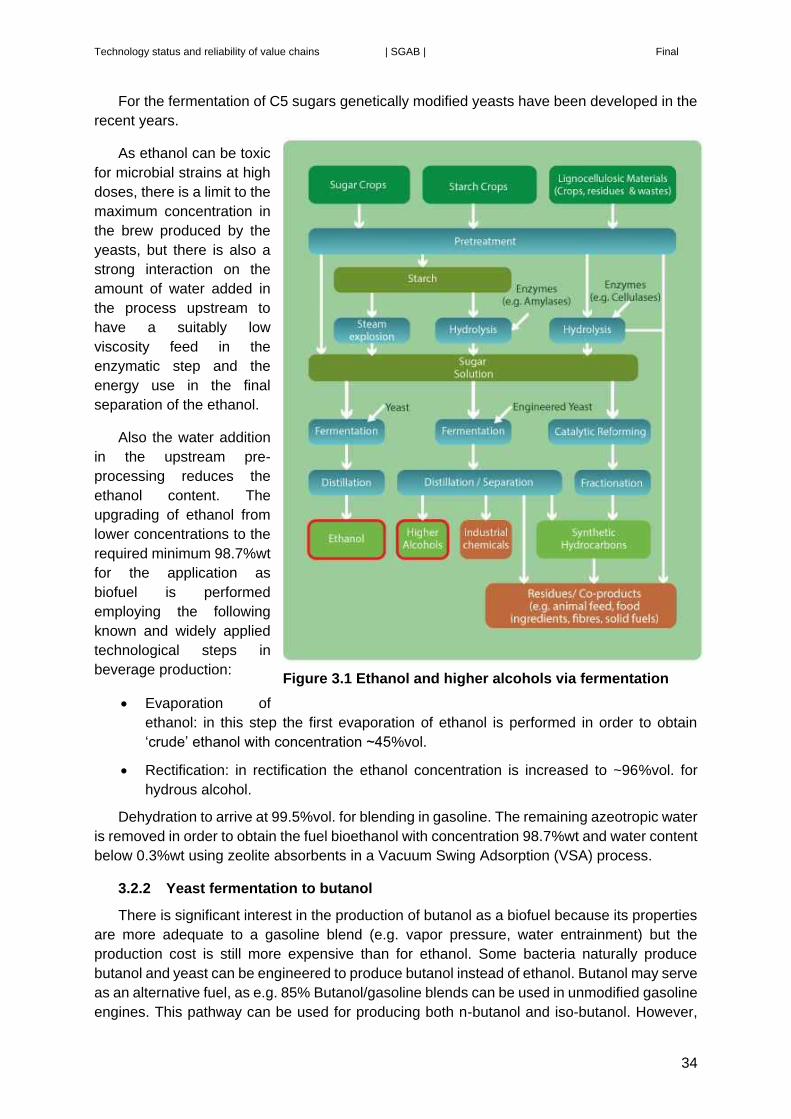
Technology status and reliability of value chains | SGAB | Final
34
For the fermentation of C5 sugars genetically modified yeasts have been developed in the
recent years.
As ethanol can be toxic
for microbial strains at high
doses, there is a limit to the
maximum concentration in
the brew produced by the
yeasts, but there is also a
strong interaction on the
amount of water added in
the process upstream to
have a suitably low
viscosity feed in the
enzymatic step and the
energy use in the final
separation of the ethanol.
Also the water addition
in the upstream pre-
processing reduces the
ethanol content. The
upgrading of ethanol from
lower concentrations to the
required minimum 98.7%wt
for the application as
biofuel is performed
employing the following
known and widely applied
technological steps in
beverage production:
Evaporation of
ethanol: in this step the first evaporation of ethanol is performed in order to obtain
‘crude’ ethanol with concentration ~45%vol.
Rectification: in rectification the ethanol concentration is increased to ~96%vol. for
hydrous alcohol.
Dehydration to arrive at 99.5%vol. for blending in gasoline. The remaining azeotropic water
is removed in order to obtain the fuel bioethanol with concentration 98.7%wt and water content
below 0.3%wt using zeolite absorbents in a Vacuum Swing Adsorption (VSA) process.
3.2.2 Yeast fermentation to butanol
There is significant interest in the production of butanol as a biofuel because its properties
are more adequate to a gasoline blend (e.g. vapor pressure, water entrainment) but the
production cost is still more expensive than for ethanol. Some bacteria naturally produce
butanol and yeast can be engineered to produce butanol instead of ethanol. Butanol may serve
as an alternative fuel, as e.g. 85% Butanol/gasoline blends can be used in unmodified gasoline
engines. This pathway can be used for producing both n-butanol and iso-butanol. However,
Figure 3.1 Ethanol and higher alcohols via fermentation

Technology status and reliability of value chains | SGAB | Final
35
the latter also has a high value as a chemical building block (Gevo, Butamax). At present there
are no quality standards for using butanol as a blend with gasoline.
3.2.3 Microbial Fermentation via Acetic Acid
Microbial fermentation of sugars can also use an acetogenic pathway to produce acetic
acid without CO2 as a by-product. This increases the carbon utilization of the process. The
acetic acid is converted to an ester which can then be reacted with hydrogen to make ethanol.
The hydrogen required to convert the ester to ethanol could be produced through
gasification of the lignin residue. This requires fractionation of the feedstock into a sugar stream
and a lignin residue at the beginning of the process (Zeachem).
3.2.4 Pilots, Demonstration and Commercial plants
3.2.4.1 The Hugoton Plant, Kansas, USA
Abengoa, which also was producing first generation ethanol in several installations in the
EU and USA, has developed its lignocellulosic ethanol technology based on data received
from its pilot plant (capacity 100 m3/year) which was started up 2007 in the US and its
Salamanca demonstration plant started up 2009 in Spain (capacity 5,000 m3/year). The pilot
plant was operated with a variety of feedstock materials and the demonstration plant was
initially fed with wheat straw which later was replaced by the biomass fraction separated out
from municipal solid waste material. The operational experiences have led to development of
own patented technology and development of its own enzymes for the pretreatment of the
feedstocks. Experiences from the two afore mentioned plants led to construction of the first
commercial plant in the USA. The key technologies are based on a sulfuric acid-catalysed
steam explosion pretreatment, in situ enzyme production, enzymatic hydrolysis and co-
production of C5 and C6 sugars to ethanol.
Plant Type P/D/C
Start-up year
Feedstock capacity Product
By-product
Hours in operation
Hugoton C 2014 997.7 tonnes/d
(dry)5 ~95 million
litre/yr 18 MWel n/a
The plant has (in 2016) started to export ethanol (several rail cars). Currently the plant is
going through various plant optimization issues such as feedstock handling optimization. Data
provided in the quoted article indicates an energy conversion efficiency from biomass to
ethanol of about 33%.
5 Data from http://www.abengoabioenergy.com/web/en/2g_hugoton_project/ Waste from ethanol production plus
extra biomass.

Technology status and reliability of value chains | SGAB | Final
36
Abengoa’s Hugoton Plant, Kansas, USA
3.2.4.2 Crescentino plant, Italy
The Biochemtex plant of BetaRenewables (a company in the Italian M&G Group) uses its
own technology (PROESA technology) to produce ethanol from various types of feedstocks.
The PROESA technology utilizes heat treatment followed by enzymatic hydrolysis for
pretreatment of the feedstocks. The plant is a combination of a large demonstration plant and
a commercially operated plant. The Crescentino plant was the first plant in the EU but also on
a global scale to produce cellulosic ethanol.
Plant Type P/D/C
Start-up year
Feedstock capacity
Product By-product
MW Hours in operation
Beta Renewables
C 2013 n/a 25,000 -40,000
tonnes/yr n/a --
The plant has been in operation for two years (2016) with support from NER 300 and also
from the FP7 framework program.
Production capacity varies depending on type of feedstock. Straw as feed yields less
ethanol (25,000 tonnes/year) than if the feed is e.g. Arundo (40,000 tonnes/year). Conversion
rates also vary accordingly and typical yield of ethanol can be expressed as 4.5-6.5 tonnes dry
biomass per ton of ethanol. On an energy efficiency basis (biomass to ethanol) this
corresponds to 32% to 22%.
Feedstock quality/consistency is listed as the most challenging variable effecting
production and plant availability.

Technology status and reliability of value chains | SGAB | Final
37
Biochemtex’ Crescentino plant, Italy DuPont’s Nevada Plant, Iowa, USA
3.2.4.3 DuPont’s Nevada Plant, Iowa, USA
DuPont has constructed and is currently commissioning a commercial sized cellulosic
ethanol facility in Nevada, Iowa (US). The technologies used in the plant are developed and
owned by DuPont. The process used to convert these feedstocks involves mild alkaline
pretreatment, Bio-catalytic saccharification (enzymes) and fermentation (both C5 and C6
sugars), ethanol recovery, filtration, evaporation, and anaerobic digestion.
Plant Type P/D/C
Start-up year Feedstock capacity
Product By-product
MW Hours in operation
Nevada C Target 2016 ~960 tonnes/d ~247 tonnes/d -- ----
On a yearly basis the plant will use 350,000 dry tonnes of corn stover to produce 90,000
tonnes of ethanol. Key areas of concern which may affect ability to attract many licensees of
the DuPont Cellulosic Ethanol Technology are clarity and stability of biofuel regulation,
biomass collection and supply, capital requirement and cost of operation. Starting up of a first
of its kind plant and technology licensing business during a period of very low oil prices is also
challenging.
3.2.4.4 GranBio’s Bioflex 1 Plant, Alagoas, Brazil.
The Bioflex 1 plant is owned by GranBio and is utilizing the PROESA two-stage
pretreatment steam explosion technology from BetaRenewables, enzymes from Novozymes
in Denmark, and yeast from DSM in Holland. The Bioflex plant is co-located with an existing
first-generation ethanol plant from sugarcane. Both facilities only share a common CHP unit
integrated in the same site that uses both sugarcane bagasse (1G plant) and lignin (from 2G
plant). The integrated power unit coproduce 70 MWel, having a surplus of 50 MWel sold to the
grid. The PROESA technology is the first to have been licensed and used in two commercial
facilities.
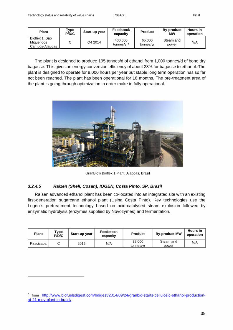
Technology status and reliability of value chains | SGAB | Final
38
Plant Type P/D/C
Start-up year Feedstock capacity
Product By-product
MW Hours in operation
Bioflex 1, São Miguel dos Campos-Alagoas
C Q4 2014 400,000
tonnes/yr6 65,000
tonnes/yr Steam and
power N/A
The plant is designed to produce 195 tonnes/d of ethanol from 1,000 tonnes/d of bone dry
bagasse. This gives an energy conversion efficiency of about 28% for bagasse to ethanol. The
plant is designed to operate for 8,000 hours per year but stable long term operation has so far
not been reached. The plant has been operational for 18 months. The pre-treatment area of
the plant is going through optimization in order make in fully operational.
GranBio’s Bioflex 1 Plant, Alagoas, Brazil
3.2.4.5 Raizen (Shell, Cosan), IOGEN, Costa Pinto, SP, Brazil
Raísen advanced ethanol plant has been co-located into an integrated site with an existing
first-generation sugarcane ethanol plant (Usina Costa Pinto). Key technologies use the
Logen´s pretreatment technology based on acid-catalysed steam explosion followed by
enzymatic hydrolysis (enzymes supplied by Novozymes) and fermentation.
Plant Type P/D/C
Start-up year Feedstock capacity
Product By-product MW Hours in operation
Piracicaba C 2015 N/A 32,000
tonnes/yr Steam and
power N/A
6 from http://www.biofuelsdigest.com/bdigest/2014/09/24/granbio-starts-cellulosic-ethanol-production-at-21-mgy-plant-in-brazil/

Technology status and reliability of value chains | SGAB | Final
39
3.2.4.6 POET-DSM Liberty Plant, USA
POET-DSM Advanced Biofuels company is a 50/50 joint venture between POET LLC and
Royal DSM. This second-generation cellulosic ethanol plant, is co-located with a grain-based
1G ethanol plant, and uses a proprietary biomass pretreatment technology contracted to
ANDRITZ (through the US ANDRITZ subsidiary) based on a two-stage acid-catalysed steam
explosion, followed by enzymatic hydrolysis with DSM-tailored enzymes. The fermentation of
C5 and C6 sugars occurs in a single pot using DSM engineered yeast. The lignin streams as
well the waste organic streams from the plant are mixed and undergoes anaerobic digestion
to produce biogas for power supply.
Plant Type P/D/C
Start-up year
Feedstock capacity
Product * By-product Hours in operation
Project LIBERTY
D/C 2015 770 tonnes/d
(bone dry) corn stover7
60,000 tonnes/yr (or 20 million gallon/yr)
Energy (steam and
biogas)
Currently in ramp-up;
proprietary
The plant is currently (2016) ramping up production to full capacity. Information regarding
performance is not provided. Provided information on product (at full capacity) and feedstock
gives a conversion efficiency of biomass to ethanol of 33%. This is under the assumption that
the plant is planned to be operated 8,000 full load hours per year.
The plant has started to ship product periodically by rail and the plan is to be at full capacity
by year end 2016. Ramp-up efforts are primarily focused on improving biomass flow in
pretreatment.
When the plant is in full operation the intension is to license the technology/process
package for replication.
POET-DSM Liberty Plant, USA The SEKAB Plant, Sweden
7 at full capacity
Technology status and reliability of value chains | SGAB | Final
40
3.2.4.7 The SEKAB Plant, Sweden
The SEKAB plant utilizes the following technologies:
The plant is utilizing SEKAB’s CelluAPP™ technology.
Pretreatment of the feedstock with heat and catalyst (alkali or acid if needed) followed
by steam explosion.
Enzyme hydrolysis (in batch or continues operation) with detoxing technology.
Separation of hydrolyzed sugars before enzymatic hydrolysis
Separation of sugars (if that is the end product, alternatively a lignin free sugar solution
is desirable) Evaporation of the liquid to get a higher sugar concentration is possible.
Fermentation with yeast or bacteria for production of ethanol or other chemicals
Separation of solid and liquid before or after fermentation (SHF, SSF).
Distillation of the final product. Separation of solids possible after distillation
Plant Type P/D/C
Start-up year Feedstock capacity8
Product By-product Hours in operation
SEKAB P 2005 2 tonnes/d (dry) (=10.6 MWh/d)
3.5 MWh/d (ethanol)
4 MWh/d (lignin) 1MWh/d (biogas)
>50,000
The longest continuous run with the same process parameters has been 4 weeks. The
plant is a development plant. For ethanol production the targets have been met but for other
applications work is ongoing.
A potential technology barrier is obtaining a long term stable process with biocatalysts like
enzymes and yeast.
The next step is to build the first reference plant in a production scale that can produce
ethanol or other chemicals based on the SEKAB CelluAPP™ technology. One project with this
goal is the CEG Plant Goswinowice in Poland, where NER300 support was received, but where
activities have not yet started.
3.2.4.8 The Butamax plant, United Kingdom
Butamax™ Advanced Biofuels, LLC was formed to develop and commercialize biobutanol
as a next generation renewable biofuel and chemical. The company benefits from the synergy
of DuPont’s proven industrial biotechnology experience and BP’s global fuels market
knowledge. The Butamax™ plant demonstrates the microbial production of isobutanol as a
single fermentative product, the process engineering for recovering biobutanol produced
during fermentation, engineering design for optimized energy integrations, and various
renewable fuel and chemical compositions.
8 soft wood as feedstock (about 1 tonne/d on straw)

Technology status and reliability of value chains | SGAB | Final
41
Plant Type P/D/C
Start-up year Feedstock capacity
Product By-product
MW Hours in operation
Hull P 2011 0.2-0.3
tonnes/d
0.057-0.068 tonnes/d of Isobutanol
n/a
n/a Batch unit runs
continuously since 2011
The process is a batch process, which has been operated batch-after-batch for most of the
last 4 years with planned shutdown for equipment changes and safety inspections. The pilot
plant has now been mothballed because piloting testing is complete. No technical barriers have
been reported so far.
3.2.4.9 The Inbicon plant, Denmark
The plant has been used to demonstrate different process configurations. The most
relevant configurations to mention are:
- Version 1: 2G Bioethanol based on C6 fermentation
- Version 2: 2G Bioethanol based on C5 and C6 fermentation.
The capacity of different unit operations was fitted to obtain a plant capacity of 4 t/h of
straw input. Change of process configuration reduced the capacity of some unit operation and
therefore also the overall capacity of the plant.
The key technologies used in the Inbicon demonstration plant (Kalundborg, DK) are a
three-stage continuous process:
(1) biomass mechanical conditioning;
(2) hydrothermal pre-treatment followed by
(3) a pre-enzymatic hydrolysis at high dry matter consistency (up to 30% d.m.) which
provides a continuous liquefaction.
Plant Type P/D/C
Start-up year Feedstock capacity
Product By-product Hours in operation
Inbicon Version 1
D 2010 96 tonnes/d (86% dry)
13 tonnes/d ethanol
30 tonnes/d lignin (90% dry)
45 tonnes/d C5 molasses (65% dry)
15,000
The plant was operated in a continuous mode during 2010 and 2011. The plant produced
98MWh/day of ethanol, 167MWh/day of lignin and 104MWh/day of C5-molasses from
386MWh/d of straw. The yield of ethanol was according to expectations.
In the first period of operation there were issues with impurities in the feedstock influencing
the performance as well as excessive wear of certain equipment. These hurdles were
overcome during the first year of operations.
Next step in development included conversion of both C6 and C5 sugars. The plant was
then operated as follows.

Technology status and reliability of value chains | SGAB | Final
42
Plant Type P/D/C
Start-up year Feedstock capacity
Product By-product Hours in operation
Inbicon Version 2
D 2013 24 tonnes/d (86% dry)
4.5 tonnes/d ethanol
9 tonnes/d lignin (90% dry)
7 tonnes/d C5 molasses (65% dry)
5,000
During 2013 and 2014 the plant was operated in campaigns of typically 4-6 weeks. The
longest run lasted 9 weeks. In this version 2 technology using C5/C6 mixed sugar fermentation
to ethanol the ethanol yield did improve 40%, from 200 litres/dry ton feedstock (v1) to 280-300
litres/dry ton feedstock (version 2). In version 2 the only co-product is lignin pellets used for
power generation in a CHP plant nearby that belongs to the group DONG Energy.
The plant produced 34MWh/day of ethanol, 50MWh/day of lignin and 10MWh/day of C5-
molasses from 97MWh/d of straw. The yield of ethanol was according to expectations.
DONG Energy’s Inbicon plant, Kalunborg, Denmark The Borregaard plant, Sarpsborg, Norway
3.2.4.10 The Borregaard plant, Norway
The key technologies used in the Borregaard plant called BALI technology are a sulfite-
based cooking pretreatment followed by enzymatic hydrolysis of the pretreated biomass,
fermentation of the sugars to ethanol and processing of the lignin to value added performance
chemicals.
Plant Type P/D/C
Start-up year
Feedstock capacity
Product By-product Hours in operation
Sarpsborg D 2013 1,200 tonnes/d
(spruce)
0.28 tonnes/d ethanol 0.46 tonnes/d
lignin chemicals
0,27 ton/d CO2
>23,000
The longest continuous run in the plant has been about 6 weeks. The plant has basically
met all targets and no technology barriers have been identified. The next step is therefore to
construct a commercial plant and Borregaard is actively pursuing that. Full scale plant data are
based on input of 300,000 dry tonnes/yr of spruce which is expected to be converted to

Technology status and reliability of value chains | SGAB | Final
43
138,000 tonnes/yr of lignin chemicals, 82,000 tonnes/yr ethanol (as 100%) with additional
80,000 tonnes/yr of CO2.
3.2.4.11 IFP’s Futurol pilot, Pomacle, France
IFP’s Futurol process includes hydrothermal pretreatment technology followed by SSF
(hexoses and pentoses) to produce bioethanol for biofuels and sustainable chemistry.
The plant comprises the following process steps: grinding, pretreatment, hydrolysis &
fermentation, enzyme production, yeast propagation, distillation, lignin separation, stillage
recycling, soluble sugars recovery.
Plant Type P/D/C
Start-up year Feedstock capacity
Product * By-product Hours in operation
Pilot, Reims, F
P 2011 16GJ/d 0,25 tonnes/d
(=7GJ/d) 7 GJ/d9 2,000 h/y
The plant has been operated mainly to solve interface and transfer issues and was able to
prove pretreatment and biological operation at pilot scale. Effect of scale-up for pre-treatment
needs to be developed and proven.
IFP’s Futurol pilot, Pomacle, France IFP’s Futurol Demonstration, Bucy-le-Long, France
3.2.4.12 IFP’s Futurol Demonstration, Bucy-le-Long, France
The demonstration plant uses hydrothermal pre-treatment technology at industrial scale to
produce pre-treated raw material suitable for down post processing in pilot plant, to produce
bioethanol for biofuels and sustainable chemistry.
9 can be burnt in industrial plants

Technology status and reliability of value chains | SGAB | Final
44
The plant specifically focuses feedstock handling, stone and metal removing, pre-treatment
and energy recovery of steam used during hydrothermal process, and recycling of soaking
liquor.
Plant Type P/D/C
Start-up year Feedstock capacity
Product By-product Hours in operation
Bucy-le-Long, F
D 2016 1,600 GJ/d 700 GJ/d 700 GJ/d May 2016, the
plant is on start-up
The purpose of the plant is to study the effect of scale-up for pretreatment and other
process parts in view of a future commercialization.
3.2.4.13 Clariant development plant, Straubing, Germany
The key technologies used in the Clariant development plant are process steps for the
fully-integrated production of cellulosic ethanol from agricultural residues. These consist of
chemical-free steam pre-treatment, integrated on-site enzyme production, hydrolysis, solid-
liquid separation, fermentation of C5/C6 sugars to ethanol, and ethanol purification.
Plant Type P/D/C
Start-up year Feedstock capacity
Product By-product Hours in operation
Clariant D/C 2012 ~15 tonnes/d ~3 tonnes/d ~4,5 tonnes/d
(lignin) ~30,000
Operation ramped up during 2012 and from 2013 until today the plant has been in
continuous operation including test and optimization runs. Overall energy efficiency is that
0.95MW of ethanol is produced from 3MW of feedstock (straw). 1.2MW of lignin is generated
as a by-product. The plant has met yield targets for the most prominent feedstock. Additional
improvement potentials or process optimizations have been identified and either implemented
at the plant already or included in the R&D pipeline.
No technical barriers remain according to the developers but feedstock supply at
economically attractive prices are still challenging.
The next step is to extend the feedstock basis proven in performance runs and continue to
further optimize the process for next generation plants. Support was made available by a FP7
demonstration project for a scale-up.

Technology status and reliability of value chains | SGAB | Final
45
Clariant’s development, Straubing, Germany Cellunolix® plant under construction, Kajaani,
Finland
3.2.4.14 Cellunolix® demonstration plant, Kajaani, Finland
The Finnish investor, North European Bio Tech Oy (NEB), an associated company of SOK
Corporation and energy company St1, is finalising a construction of bioethanol plant on the
Renforsin Ranta industrial estate in Kajaani, Finland. Commissioning of the unit will take place
during 4th quarter of 2016. The GHG reduction will be up to 90% vs. fossil comparator (RED
calculation methodology). The raw material for the plant is sawdust from local sources.
The plant design is based on the St1 proprietary technology. Unit operations are typically
based on commercially available technology packages. The plant is being delivered by St1
Biofuels Oy who is also responsible for design, permits and coordination and will be operating
the plant once it is completed. Earlier St1 has built eight small scale waste or residue to
bioethanol plant in Finland and in Sweden.
The process contains: acid catalyst based pre-treatment, hydrolysis, fermentation, lignin
separation, evaporation, distillation, turpentine and furfural recovery units and utility stations.
Lignin and evaporation residues are converted, fed in to the boiler plant in the vicinity.
Fermentation organism utilize mainly C6 sugars while majority of C5 sugars remain as future
potential. Some furfural is produced as a by-product but currently there are no recovery and
utilization for this amount. It will be rectified and burned at boiler.
Target for the Cellunolix® Kajaani is to prove that softwood is technically and economically
feasible raw material for bioethanol process. Compared to hardwood that is more common
feedstock for bioethanol, softwood contains wood extractives (tar components) such as
turpentine and resin acid that have to be removed. Saw dust is very homogeneous raw material
and contains less foreign particles than other forest or agricultural residues.
Plant Type P/D/C
Start-up year Feedstock capacity
Product By-
product
Hours in operation
Cellunolix® Kajaani D/C 2016 ~270
tonnes/d (55% water)
~ 24 tonnes/d ~ 430 MW/d
Cellunolix® (EIA in process)
C 2019 ~120 tonnes/d

Technology status and reliability of value chains | SGAB | Final
46
Alternative use for saw dust raw material is the incineration in the nearby boiler plant. But,
since the moisture content of the solid residue after the bioethanol plant is lower than the
moisture content of the fresh saw dust, the residue has higher caloric value.
Next larger capacity similar plant is already in design phase. Environmental Impact
Assessment is on-going for three different locations. Production process and commercial
feasibility of the first Cellunolix® unit is a key prerequisite for the investment decision,
envisaged to take place in 2018.
3.3 Hydrocarbons from sugar-containing material via biological
and/or chemical processes
3.3.1 Via microbial fermentation
Farnesene
Engineered yeasts can be used to
ferment sugar into a class of compounds
called isoprenoids which includes
pharmaceuticals, nutraceuticals, flavours
and fragrances, industrial chemicals and
chemical intermediates, as well as fuels.
One of these isoprenoids is a 15-carbon
hydrocarbon, beta-farnesene. Beta-
farnesenes can be chemically derivatized
into a variety of products, including diesel, a
surfactant used in soaps and shampoos, a
cream used in lotions, a number of
lubricants, or a variety of other useful
chemicals. It has also been accepted for 10
% blending in jet fuel as Synthesized Iso-
Paraffinic fuel, (SIP) in the ASTM D7566
standard. This process is applied by Amyris.
3.3.2 Routes involving catalytic upgrading of sugars or platform chemicals that
can be produced from sugars
Several different hydrolysis technologies can be used to solubilize lignocellulose to sugars,
see section 0. These sugars can be further upgraded to fuels or fuel components at least
through three routes:
using the sugars as a feedstock for fermentation of chemicals that can be used as fuel
components like ethanol, which can then be further catalytically oligomerized to
produce hydrocarbons (as described in the previous section),
converting the sugars into hydrocarbons catalytically in so called aqueous phase
processing, and,
Figure 3.2 Hydrocarbons from sugar-containing material

Technology status and reliability of value chains | SGAB | Final
47
converting the sugars into platform chemicals, such as Hydroxy-Methyl-Furfural
(HMF), furfural or levulinic acid that can be further upgraded catalytically to fuel
components or hydrocarbons.
3.3.3 Catalytic Reforming
Soluble carbohydrate streams can consist of a wide range of molecules such as C5/C6
sugars, polysaccharides, organic acids, furfurals and other degradation products generated
from the deconstruction of biomass. These can be processed through Aqueous Phase
Reforming (APR). The aqueous phase reforming step utilizes heterogeneous catalysts
including zeolites, metals and noble metals at temperature and pressure (200 - 250°C, 3 -
5MPa) to reduce the oxygen content of the carbohydrate feedstock. Some of the reactions in
the APR step include:
reforming to generate hydrogen;
dehydrogenation of alcohols/hydrogenation of carbonyls;
deoxygenation reactions;
hydrogenolysis and
cyclization.
Hydrogen is produced in-situ from the carbohydrate feedstock. The product from the APR
step is a mixture of chemical intermediates including alcohols, ketones, acids, furans, paraffins
and other oxygenated hydrocarbons. Once these intermediate compounds are formed they
can undergo further catalytic processing to generate a mixture of non-oxygenated
hydrocarbons.
The chemical intermediates from the APR step can be react over a zeolite catalyst (ZSM-
5) to produce a high-octane gasoline blend stock that has a high aromatic content similar to a
petroleum-derived reformate stream. APR is being commercialized by Virent.
3.3.4 Pilots, Demonstration and Commercial plants
3.3.4.1 The Virent plant, USA
Virent has piloted two different technologies that convert sugars to “direct replacement”
hydrocarbons: (1) sugar to reformate process and (2) sugar to distillate process. Both
processes utilize Virent Aqueous Phase Reforming (APR) technology to first stabilize and
deoxygenate the sugar feedstocks. The sugar to reformate process utilizes a second catalytic
step that converts oxygenates derived from the APR technology to a highly aromatic reformate
that can be fractionated and blended into the gasoline pool, the jet fuel pool, and the diesel
fuel pool. The sugar to distillate process utilizes a different second catalytic step that converts
the oxygenated derived from the APR to longer carbon chain paraffins and cyclic paraffins that
are primarily in the jet fuel and diesel fuel boiling range.
Both larger scale pilot plants operated as designed and proved that the two technologies
could be scaled utilizing bench top pilot plant data.

Technology status and reliability of value chains | SGAB | Final
48
Plant Type P/D/C
Start-up year Feedstock capacity
Product By-product
MW Hours in operation
“Eagle” Pilot P 2009 0.35 tonnes/d 0.10
tonnes/d n/a 6,200
“Falcon” Pilot P 2013 0.12 tonnes/d 0.05
tonnes/d n/a 1,200
The Eagle plant converts sugar to gasoline reformate while the Falcon plant produces
distillates instead. The former product was blended into either the gasoline pool, into jet fuel,
or into diesel fuel as well as used as a feedstock to generate paraxylene while the latter was
fractionated and blended into either the gasoline pool, jet fuel pool or diesel fuel.
The Eagle plant has operated in seven (7) different campaigns for a total of 6,200 hours
where the longest lasted 3,500 hours while the Falcon plant has operated one campaign for
1,200 hours.
Virent’s Demonstration Unit for Sugar to Gasoline Swedish Biofuels Pilot, Stockholm, Sweden
3.3.4.2 The Swedish Biofuels Pilot, KTH, Sweden
The pilot is demonstrating the Swedish Biofuel production method in which the feed are
alcohols (C2-C5), obtained from biochemically converted wood waste or agricultural waste etc.
by technologies described elsewhere in this report, are converted into hydrocarbons. The
alcohols are produced by other cellulosic processes.
In the process developed, the alcohol mixture is then dehydrated into a mixture of the
corresponding olefins. In the second stage, the olefins, together with carbon monoxide and
hydrogen obtained e.g. by gasification or dry reforming of biogas using CO2 from alcohol
fermentation, are synthesized into higher alcohols. In subsequent stages, the higher alcohols
are again dehydrated to olefins, which are then condensed into higher unsaturated
compounds, including aromatics. At the final stage, the higher unsaturated compounds are
hydrogenated to yield the corresponding paraffins. The mixed hydrocarbon product stream is
separated into gasoline, kerosene and diesel by rectification.

Technology status and reliability of value chains | SGAB | Final
49
Plant Type P/D/C
Start-up year Feedstock capacity
Product Jet SB-JP-8
By product, Biogas, Gasoline
and Diesel
Time in operation
h/year
ATJ P 2009 0.040 MW
(C2-C5 alcohols) 0.015 MW 0.020 MW
7,200 for a total of
>40,000 hours
The plant has been in operation since 2009. The plant capacity has been increased over
the years from an initial 5 tonnes/y to the current 20 tonnes/yr. The final products are fully
synthetic motor fuels of kerosene, gasoline and diesel, which comply with the standard fossil
fuel specifications for use in standard engines. Alcohols in the range C2 - C5 have been used
as feedstocks for the pilot plant, either as a single alcohol or as a multi-component mixture,
confirming the reproducibility of the process.
There are no expected technology barriers. The potential show stopper is the continuing
low price of fossil oil.
The next step in the development of the technology is the construction of a pre-commercial
industrial scale plant during the period of 2015-2019. The project is supported by an FP7 grant
from the European Commission. The main goal of the project is the production of synthetic
biofuels for use in aviation. The project will use the Alcohol to Jet (ATJ) pathway, as an
alternative to the technologies available today, for the production of drop-in aviation fuels. The
capacity of the plant will be 10,000 tonnes/yr, of which half will be aviation fuel with the rest
being ground transportation fuels.
3.3.4.3 The Amyris plant in Brazil
The Amyris industrial production plant in Brotas, Brazil converts sugarcane syrup into
farnesene and other tailored molecules for a range of renewable products including a
biocomponent for the diesel and jet-fuel (SIP).
Plant Type P/D/C
Start-up year
Feedstock capacity
Product
By-product MW
Hours in operation
Amyris C 2012 n/a 40 tonnes/d none 20,500
Plant operations have been smooth with no potential show-stoppers or technology barriers.
The longest run has been 11 months.

Technology status and reliability of value chains | SGAB | Final
50
Amyris’ plant, Brotas, Brazil
3.4 Biomethane via anaerobic digestion
3.4.1 Feedstocks
Typical feedstocks for biomethane production are wet waste fractions from the agriculture
and food industry sector and sludges from e.g. water treatment works in both cities and
industries. One special case is recovery of landfill gas from waste landfills to prevent release
of the methane formed over
decades into the atmosphere.
Anaerobic digestion of organic
material to biogas, a mixture of
almost equal parts of methane and
CO2 with some trace gases (mainly
nitrogen and sulphide), has a long
history. In agricultural digestion it
has recently reached a certain
standard while the design of
industrial plants is still under a
strong development. All biomass
fractions with the exception of lignin
can be degraded by anaerobic
microbes, however a pretreatment
of lignocellulosic compounds is
strongly recommended to make the
cellulose and hemi-cellulose better
available for the bacterial
degradation. This pretreatment
might be enzymatic, chemical or
physical. It is fairly comparable to
the pretreatment for alcohol
production from lignocellulosic
material.
The residues and waters after digestion contain dissolved organics and inorganics as well
as non-digested solids. Depending of the feed, these residues can have a value as e.g.
fertilizers or require other treatments prior to their disposal.
Figure 3.3 Biomethane via anaerobic digestion

Technology status and reliability of value chains | SGAB | Final
51
3.4.2 Compressed Bio-Methane (CBM)
Out of the total of some 17,000 biogas plants in Europe over 95% are decentralized
combined heat and power plants (CHP) at small scale (average 0.5 MWel). However, with the
reductions in feed-in tariffs for electricity the application of biogas in transport becomes
increasingly important.
There are only close to 400 plants where the bio-gas was upgraded to bio-methane. Half of
these were in Germany, some 60 plants in Sweden and some 40 plants in the UK. The total
production of bio-methane is estimated to be 14 TWh or 1.2 million tonnes of oil equivalent
(toe). In order to reach the fuel quality standards for transportation and injection into the gas
grid the raw biogas must be upgraded to gas with equivalent quality characteristics to natural
gas. The CH4 content of the biogas must be increased (> 97% CH4) by removing most of the
CO2 from the biogas. Furthermore, the gas has to be dried and different trace gases (H2S,
siloxanes) have to be removed. Commercially available upgrading technologies which are
used for the treatment of biogas include pressure swing absorption, pressurized water
scrubbing, physical absorption, amine washing and membrane separation. The technologies
are equally present across Europe, with water scrubbers taking the lead.
Bio-methane is perfectly suited to be used as a ‘drop in’ fuel in the existing natural gas
systems. Europe has an extended gas grid allowing transporting also bio-methane which can
be blended at any ratio with natural gas.
3.4.3 Liquefied Bio-Methane (LBM)
Where gas grids are not available, bio-methane can be turned into a liquefied state, a
product known as liquefied bio-methane (LBM). Apart from logistic benefits, the major
opportunity of LBM is the use in modified heavy duty vehicles allowing them to operate in a
same range as with diesel of 800 km to 1,000 km. LBM can be transported with via insulated
tanker trucks designed for transportation of cryogenic liquids to filling stations for either
Liquefied Natural Gas (LNG) vehicles or Compressed Natural Gas (CNG) vehicles.
Liquefaction of biogas can be combined with the upgrading process allowing the production
of two products, LBM and liquid CO2 which brings an additional financial income. Currently two
different systems are on the market, a fully integrated upgrading and liquefaction process
developed by GIS in The Netherlands and a sequential upgrading and liquefaction process
where the off-gas can be recycled for a close to 100% recovery of both CH4 and CO2.Pentair
Haffmanns was the first introducing this technology.
The number of LBM plants is increasing fast. Sweden was the forerunner with a first large
plant in Lidköping10, 60 GWh followed by the United Kingdom (UK) and the Netherlands. But
also in the USA biogas is upgraded and liquefied on a landfill in Livermore.
10 http://www.iea-biogas.net/case-studies.html

Technology status and reliability of value chains | SGAB | Final
52
3.4.4 Pilots, Demonstration and Commercial plan
3.4.4.1 Bio-methane plant of Malmberg/Västblekinge Miljö AB in Mörrum, Sweden
Malmberg’s upgrading plant in Mörrum, Sweden, upgrades biogas to 99% pure bio-
methane. The gas is stored in gas bottles and sold to the international power company EON,
which provides it to their vehicle gas stations. Three municipalities are filling up their local
busses with the resulting bio-methane. The feedstock is organic waste collected from around
250,000 people resulting in 18,000 tonnes of pure organic waste which is then dry digested
producing 3,000 tonnes of biogas. The waste also generates 7,500 tonnes for composting and
7,500 tonnes recycles to fertilization.
Plant Type P/D/C
Start-up year Feedstock capacity
Product Nm3/h
By-product Hours in operation
Biomethane plant of Malmberg/Västblekin-ge Miljö AB
C 2004;
New upgrading unit in 2015
~ 55 tonnes/d
400 20.5 tonnes/d compost and
digestate >50,000
The digestion method used is dry fermentation, meaning that food waste is digested in
from the way it is generated, i.e. with no additional water mixed in. This provides a stable and
energy efficient operation where the food waste is digested. Technology barriers are that the
produced bio-methane cannot be injected into the grid as the Swedish gas network does not
reach up to Mörrum. However, the bottling technique works well. Furthermore, a gas station is
under construction at the Mörrum site that will provide all waste collecting vehicles with bio-
methane at the same time they are unloading waste to the station.
Biomethane plant of Malmberg/Västblekinge Miljö AB in Mörrum, Sweden
Biomethane plant of Biogest Biogas/Greener for Life Ltd in Somerset, the UK
3.4.4.2 Bi-methane plant of Biogest Biogas/Greener for Life Ltd in Somerset, the
UK
The plant produces at least 4,000 MWh electricity and 7.2 million m3 of biogas/4.3 million
m3 of biomethane (40GWh) yearly using optimized feedstock mix of cattle slurry and manure,
sugar beet, grass silage and maize silage.

Technology status and reliability of value chains | SGAB | Final
53
Feedstock deliveries to the Anaerobic Digestion (AD) plant with upgrade system enables
the farmer to sustainably utilize the farm wastes while allowing the farmer to manage the
manure and crop rotations more efficiently.
The plant is a 2-stage AD plant which is suitable for operation with almost all types of
feedstock. Power output ranges from 250 - 2,000kW and a bio-methane production of 80 -
500Nm³/h. The design is based on an external main digester and an internal post-digester.
The main digester is a ring canal, thereby allowing a controlled plug flow.
Plant Type P/D/C
Start-up year Feedstock capacity
Product By-product Hours of operation
Biogas/biomethane plant of Biogest Biogas/Greener for Life Ltd
C 2014-2015 n/a 380 Nm3/h 11 MWhel/d
(fr. Biogas for CHP) + digestate
<25,000
Next step: increased biogas production
3.4.4.3 Lidköping Biogas - Air Liquide and Swedish Biogas International in
Lidköping, Sweden
The biogas production process is based on local vegetable waste products from grain trade
and food production. The substrates are macerated, mixed and heated to 38°C before being
pumped into the digestion chamber. New substrate material is continually pumped into the
process that produces biogas and bio fertilizer. The bio-fertilizer is pumped to a covered
storage pool.
Plant production is designed at 7.5MWth with an annual target of 60GWhth. Swedish Biogas
International AB designed the production plant. The biogas is upgraded in accordance with the
Swedish standard for biogas as a vehicle fuel in a water scrubber. A majority of the biogas is
liquefied in the condensation plant. In order to liquefy the biogas, the majority of remaining CO2
(down to <10ppm) is purged by Pressure Swing Absorption (PSA) system before the gas
temperature is lowered using the Brayton cycle. The technology allows for liquefaction in the
span of 140 C (at 0.5MPa) to 161 C (at atmospheric pressure), depending on the developing
requirements of the vehicle market. The liquefied biogas is stored in a 115m3, 20m tall insulated
canister. The distributer, Fordonsgas Sverige AB (FGS), fills insulated 50m3 trailers every
second day and transports the gas to filling stations in Gothenburg. A smaller portion (around
30%) of the biogas produced and upgraded to biomethane is delivered directly to FGS’s two
compressors, which fills mobile storage containers in one of six filling places.
Plant Type P/D/C
Start-up year
Feedstock capacity
Product By-product Hours of operation
Lidköping Biogas - Air Liquide and Swedish Biogas International
C 2011 220 tonnes/d 12 tonnes/d (liquified bio-
methane)
1 MW (com-pressed bio-
methane) 25,000

Technology status and reliability of value chains | SGAB | Final
54
As the demand for liquefied biomethane increases in Sweden, production of compressed
biomethane at Lidköping plant will decrease.
Lidköping Biogas - Air Liquide and Swedish Biogas International in Lidköping, Sweden
NGF Nature Energy in Holsted, Denmark Picture by NGF Nature Energy
3.4.4.5 NGF Nature Energy in Holsted, Denmark
NGF Nature Energy opened the Holsted Biogas plant in August 2015. The plant processes
around 400 thousand tons of waste per year, split roughly between 75% agricultural waste,
mainly manure and deep litter, and 25% industrial waste. The biogas produced is cleaned,
upgraded to natural gas quality equivalent and injected into the grid. Production of bio-methane
at the plant is 1,800Nm3/h of pure methane, which equates to 130GWh, or the annual
consumption of circa 8,000 households in Denmark, or fuel for 17,500 gas vehicles per annum.
Plant Type P/D/C
Start-up year Feedstock capacity
Product By-product
MW Hours of operation
NGF Nature Energy
C 2015 1,096 tonnes/d 1,800 Nm3/h
(bio-methane) n/a <10,000
The next step foreseen is to use of the produced bio-methane as a transport fuel.
3.4.4.6 The VERBIOgas plant in Schwedt, Germany
VERBIO’s bio-methane plant in Schwedt/Germany is operated on a very efficient mono-
fermentation process based on 100% straw as raw material. The biogas is purified and
conditioned to natural gas quality and fed into the natural gas grid. This so called bio-methane
is sold as bio-component into the CNG fuel market.
All main types of straw are tested in use and theses ones have already been approved to
be suitable for the plant: wheat straw, barley straw, rye straw, corn straw, rape straw and
triticale straw. Straw logistics is also operated and optimized by VERBIO. In accordance with

Technology status and reliability of value chains | SGAB | Final
55
the German standards for the natural gas grid the biogas produced is upgraded in an amine
scrubber. Subsequently, the bio-methane is compressed and fed into the gas grid.
In the sense of maximum sustainability and maintenance of humus balance fermentation
residues are brought back to the fields as a high-quality bio-fertilizer. The straw-bio-methane
plant has been designed as an extension to the already existing bioethanol-bio-methane plant
of VERBIO Ethanol Schwedt GmbH.
Plant Type
P/D/C
Start-
up year
Feedstock
capacity Product By-product Hours of
operation
Verbiogas
(VERBIO AG) C 2014
120 tons/d
(83% dry)
12 tons/d
(compressed bio-methane)
Bio-
fertilizer 15,000
Verbiogas is made from 100% straw was fed into the natural gas grid for the first time in
October 2014. At this time initial capacity of the plant was 8MWth. Within the next 3 years the
capacity of the plant is going to be increased to 16.5MWth with an annual target of 140GWhth
bio-methane to be fed into the grid.
VERBIOgas plant in Schwedt, Germany
3.5 Hydrocarbons and alcohols from waste gaseous material via
gas fermentation
3.5.1 Process principles
The conversion of CO rich gases through synthetic chemical pathways, for example FT or
methanol synthesis, requires that H2 be available in the synthesis gas. Industrial waste gases
(e.g. from steel industry) often do not contain sufficient H2 and therefore cannot be converted
using conventional synthetic pathways without adding processing steps.
Gas fermentation utilizes gas streams with a range of CO and H2 compositions to produce
fuels and chemicals such as e.g ethanol and 2,3-butanediol at high selectivity and yields. While
both CO/CO2 and H2 are utilized in the process, acetogenic microbes are also able to consume
H2-free CO-only gas streams, due to the operation of a highly efficient biological water gas

Technology status and reliability of value chains | SGAB | Final
56
shift reaction occurring within the microbe. This reaction allows the bacteria to compensate for
any deficit of H2 in the input gas stream by catalyzing the release of H2 from water using the
energy in CO. In the presence of H2, synthesis of ethanol, higher alcohols or hydrocarbons
from CO or CO2 via hydrogenation or conventional chemical catalysts can be costly and require
very large scale to be able to make the economics work. In addition, these processes require
high substrate purity.
This pathway offers a highly differentiated technology with feedstock and end product
flexibility. Gas fermenting microbes are claimed to be more tolerant to high levels of toxicity
than synthesis catalyst, thereby avoiding expensive conditioning. Large-scale applications
require the provision of insoluble gases into the growth medium; this challenge has been
overcome through developments in gas delivery technology.
3.5.2 Pilots, demonstrations and commercial plants
3.5.2.1 The LanzaTech Plant in Caofoedian, China
Plant Type P/D/C
Start-up year Feedstock capacity Ethanol By-product
MW Hours of operation
LanzaTech D 2013 450 Nm3/hr
H2+CO 1.4 tonnes/d n/a 6,500
3.5.2.2 LanzaTech MSW facility, Japan.
This project uses gasified MSW to produce ethanol through gas fermentation. The total number of hours the plant has been run over time is around 4,000h, run in series of campaigns.
Plant Type P/D/C
Start-up year Feedstock capacity Ethanol By-
product MW
Hours of operation
LanzaTech D 2015 15 Nm3/hr
H2+CO 0.05
tonnes/d n/a 4,000
LanzaTech’s Shougong plant, China LanzaTech’s Plant in Ghent, Belgium

Technology status and reliability of value chains | SGAB | Final
57
3.5.2.3 The LanzaTech Plant in Ghent Belgium
In Ghent, Belgium, a consortium of ArcelorMittal, LanzaTech, Primetals Technologies and
E4tech agreed to start the construction of Europe’s first-ever commercial demonstration facility
at ArcelorMittal’s integrated steel plant to create bioethanol from waste gases produced during
the steelmaking process. It is estimated that this plant will be online for around 8,000 hours
run through a series of campaigns rather than in one entire year.
Plant Type P/D/C
Start-up year
Feedstock capacity Product By-product
MW Hours of operation
LanzaTech C 2017 50,000 Nm3
H2+CO 143 tonnes/d n/a 8,000 hr/yr
The construction of the €87 million flagship pilot project commenced in 2016, with
bioethanol production expected to start mid-2017. Construction will be in two phases, with
phase one providing an initial capacity of 16,000 tonnes of ethanol per annum by mid-2017
and phase two, which will be completed in 2018, bringing the total capacity to 47,000 tonnes
of ethanol per annum.
Many of the technical difficulties with the gas fermentation system have largely been
overcome by LanzaTech during the course of the development. The process operates close
to ambient temperature and atmospheric pressure, resulting in reduced CO2 emissions and
minimizing heating and cooling costs. LanzaTech has also demonstrated the ability to
manipulate the organism for high yields of highly specific products.
After full commercial operation of the first phase unit in Ghent, the plan is that a second
facility will be constructed and operated at the same facility. Further roll out has been mapped
out by ArcelorMIttal across the EU over the next 10 years. The anticipated potential of the full
deployment at identified ArcelorMittal sites is around 300,000 tonnes of ethanol per year, or
380 million liters.

Technology status and reliability of value chains | SGAB | Final
58
4. Power to Gas and Power to Liquid conversion
Power-to-Gas (PtG) and Power-to-Liquid (PtL) refers to technologies, which convert
electric energy to another energy carrier,
like for example methane or methanol.
In short electricity is converted to
hydrogen through electrolysis. When
combined with CO2 this mixture can be
converted through catalytic synthesis into
a gaseous or liquid fuel, also called e-
fuels. Because CO2 is one of the relevant
building blocks, Power-to-X (PtX) is also
often referred to as an example of Carbon
Capture and Utilization (CCU).
Depending whether the electricity
comes from biomass (e.g. co-firing or
CHP) or from renewable source like wind
or solar, these fuels either are biofuels or
‘renewable fuels of non-biological origin’
as described in the amended RED.
As far as the CO2 is concerned there
are many different sources, either from
biologic or fossil origin as illustrated by
some examples in the table below.
Source Output Concentration Industrial flue gases Up to 700 tonnes/hr ~ 10-15% Ethanol fermentation, distilleries and breweries Up to 50 tonnes/hr ~95% Biogas purification Up to 0.7 tonnes/hr ~90%
4.1 Methane production
By methanation, CO2, captured from a point emission and the H2 produced by electrolysis
are catalyzed into CH4. Either chemical catalysis or bio-catalysis can be used for methanation.
4.2 Methanol production
Conventional methanol is primarily produced through steam reforming of natural gas into
syngas (CO, CO2 and H2) which is than reacted into methanol (CH3OH) through catalytic
conversion.
Power-to-Methanol technologies also rely on catalytic conversion technologies to convert
CO2 and H2 into methanol.
Figure 4.1 Power to G-or-L conversion pathways

Technology status and reliability of value chains | SGAB | Final
59
4.3 Adding H2 to Syngas
A gasification process typically generates a raw synthesis gas which has a H2 to CO molar
(volumetric) ratio of around 1 (0.8 to 1.3). For most synthesis processes a higher ratio is
needed, typically around 2 (methanol, FT) to 3 (methane). In order to accomplish the desired
ratio in today’s commercial plants, the raw syngas is passed through a so called water gas
shift reaction with which CO is reacted with H2O to form H2 and CO2. The reaction is exothermic
and the syngas loses about 4-7% of its heating value and results in substantial increased CO2
emissions to the atmosphere.
One method to avoid the shift is by adding hydrogen to the process in order to reach the
desired ratios. The hydrogen can be produced in the same way as hydrogen needed for the
PtG/L concepts. See Figure above. Also oxygen from the electrolysis plant can be used in the
gasification plant substantially reducing or even eliminating the need for an air separation plant.
If hydrogen addition is fully substituting the shift concept (at ratio requirement of 2) the
syngas generation and thus the production capacity increases in the order of 50% from a given
amount of biomass feedstock.
This concept is described in detail in e.g. so called GreenSynFuels Report11 as well is the
report Co-production of synthetic fuels and district heat from biomass residues, carbon dioxide
and electricity: Performance and cost analysis12.
4.4 Pilots, Demonstrations and Commercial Plants
4.4.1 Power to Hydrogen: Falkenhagen Hydrogen production and grid injection,
Germany
E.ON’s power-to-gas pilot unit in Falkenhagen, Germany has injected more than 2GWh of
hydrogen into the gas transmission system in its first year. The Falkenhagen unit uses
renewable-sourced electricity to power electrolysis equipment that transforms water into
hydrogen, which is then injected into the natural gas transmission system. With an electrolyzer
capacity of 2MW, it can produce 360Nm3/h of H2. E.ON delivers some of Falkenhagen’s
hydrogen output to its project partner, Swissgas AG, and makes some available to its
residential customers through a product called “E.ON WindGas.”
Plant Type P/D/C
Start-up year Feedstock capacity
Product By-product
MW Hours of operation
Falkenhagen D/C 2013 (max) 2.0 MWel 1.1 (H2) MW n/a 10,000
E.ON is currently building a second PtG pilot unit in Reitbrook, a suburb of Hamburg. The
purpose of this unit is to optimize the transformation process by means of more compact and
efficient electrolysis equipment.
11 http://serenergy.com/wp-content/uploads/2015/11/GreenSynFuels_report_final.pdf 12 http://www.sciencedirect.com/science/article/pii/S0961953415000070

Technology status and reliability of value chains | SGAB | Final
60
Falkenhagen Hydrogen production and grid injection,
Germany Power to Gas: Audi/ Solar Fuels e-gas, Germany
4.4.2 Power to Gas: Audi/ Solar Fuels e-gas, Germany
The largest PtG demonstration plant has been developed by Solar Fuel GmbH, for Audi
AG and built in Werlte in Germany. This plant has an electrical capacity of 6.3MWel, producing
360Nm3/h methane, which will be injected in the local gas distribution grid, and ultimately can
be certified for use in Audi’s Natural Gas Vehicles (NGV) range. The CO2 source for the
methanation process is the stripped CO2 from a waste treatment biogas plant nearby.
Plant Type P/D/C
Start-up year Feedstock capacity Product
MW By-product
MW Hours of operation
Audi D/C 2014 6.3 MWel 3.5 n/a 12,000
ETOGAS the plant constructor is expecting to be able to increase the scale to over 20MWel
input for the next generation of plant, and at the same time reduce the cost per MW
significantly.
4.4.3 Power to Gas: BioCAT Plant, Copenhagen, Denmark
The system was tested at laboratory scale using a 10 m3 reactor vessel and raw biogas as
a carbon dioxide source, and was operated for more than 3,200 hours between January and
November 2013 at Aarhus University, Foulum, Denmark. In February 2014, Electrochaea
announced the development of BioCat, its commercial scale technology demonstration project,
located at the wastewater treatment plant in Copenhagen. The main objective of the resulting
project was to design, engineer, construct, and test a 1MW PtG plant based on Electrochaea's
biological methanation technology. The project was commissioned in February 2016 and in
April 2016 it produced its first methane. When fully operational, data will be collected over a
3,000 hours period of injection into a local distribution grid. Oxygen and heat, which are
generated as by-products in the PtG process, is captured and utilized in the on-site wastewater
operations. The facility will also provide frequency regulation services to the Danish power
grid. Electrochaea acts as the project leader and is supported by Hydrogenics, Audi, NEAS
Energy, HMN Gashandel, BIOFOS, and Insero Business Services.

Technology status and reliability of value chains | SGAB | Final
61
Plant Type P/D/C
Start-up year Feedstock capacity
Product By-product
MW Hours of operation
BioCat, Electrochaea
D 2016 1 MWel and 50 m3/hr of CO2
50 (CH4) m3/h
0.1 MWth First methane produced April
2016
As a next technology step Electrochaea are looking to move to grid scale with over 10MWel
input, and are currently raising investment.
Electrochaea Biocatalytic Technology, Denmark CRI’s Power to Methanol plant, Iceland
4.4.4 CRI’s Power to Methanol: The George Olah plant, Iceland
The largest Power-to-Methanol facility has been operating in Iceland for the last 5 years.
CRI’s ‘George Olah’ Renewable Methanol Plant in Svartsengi, near Grindavik, Iceland began
production in late 2011 and was completed in 2012.
In 2015 CRI expanded the plant from a capacity of 1,300 tonnes per year to 4,000 tonnes
per year. The plant now recycles 5,600 tonnes of carbon dioxide a year which would otherwise
be released into the atmosphere.
All energy used in the plant comes from the Icelandic grid mix, which is generated from
hydro and geothermal energy. The plant uses electricity to generate hydrogen which is
converted into methanol in a catalytic reaction with carbon dioxide. The CO2 is captured from
flue gas released by a geothermal power plant located next to the CRI facility. The origin of the
flue gas are geothermal steam emissions.
The only by-products are [i] oxygen which is created as the plant uses electricity to split
water into its constituent chemicals, and [ii] water from the methanol distillation step.
Plant Type P/D/C
Start-up year Feedstock capacity Product By-product Hours of operation
G Olah D 2011 6 MW 10 tonnes/day O2 10,000
The plant has been in operation for 10,000 hours. The renewable methanol is sold to fuel
customers in Iceland, the Netherlands, UK, Denmark and Sweden.

Technology status and reliability of value chains | SGAB | Final
62
4.5 Projects under construction
4.5.1 Power to Methanol: The MefCO2 project, Germany
Carbon Recycling International (CRI), Mitsubishi Hitachi Power Systems Europe (MHPSE),
Hydrogenics, University of Duisburg and several other universities have launched a joint
demonstration of load-following operation of power-to-methanol technology with a power plant.
This will be demonstrated in the ongoing EU research project MefCO2 at the Steag owned and
operated power plant in Lünen, Germany. Full commissioning and operation at Lünen is
scheduled in 2017.
Plant Type P/D/C
Start-up year Feedstock capacity Product By-product Hours of operation
MefCO2 D 2017 1 MW 1 tonne/d O2 n/a

Technology status and reliability of value chains | SGAB | Final
63
5. Algae development
5.1 Aquatic vs. terrestrial biomass
Photosynthetic algae (including macro- and micro-algae) and photosynthetic
cyanobacteria have the potential to produce considerably greater amounts of biomass per
hectare than
terrestrial crops;
some species
could even
directly produce
fuel (H2, ethanol
or alkanes). Such
aquatic biomass
can be cultivated
on non- arable
land or even off-
shore, using sea
or brackish
water, industrial
carbon dioxide
as carbon source
and wastewater
as nutrient input
(nitrogen and
phosphorus).
Aquatic biomass
are energy crops that do not compete with food crops for land or other resources.
There are many parameters that influence aquatic biomass productivity and composition
like irradiance levels, dark/light cycles, CO2 and O2 concentration, temperature, pH, salinity
and nutrients. The maximum theoretical (dry) biomass productivity of algae can reach
100g/m2/d but real productivities in good locations are around 15-20g/m2/d at present (i.e.
70tonnes/ha/year). There are intensive R&D activities at lab and pilot scale to improve these
results.
Algae biomass composition consists of carbohydrates, proteins, lipids and other products
such as pigments, vitamins, etc., for use in food, cosmetics and other niche markets. The lipids
have been the most interesting fraction for conversion into biofuels. Oleaginous strains (at
least 20% lipid content on Dry Weight (DW) basis) can overproduce lipids (up to 70% lipids on
DW basis) under selected severe stress conditions such as N and/or Si starvation.
5.2 Cultivation
Major distinctions of cultivation methods are between on-shore/off-shore and open/closed
systems.
Large scale cultivation of microalgae in on-shore outdoor open pond systems and
raceways is well established. Cultivation in open systems is only suitable for a few algal
Figure 5.1 Algae development pathways

Technology status and reliability of value chains | SGAB | Final
64
species which can tolerate extreme environmental conditions such high salinity (Dunaliella),
high pH (Spirulina (Arthrospira)) or undergo extremely high specific growth rates (Chlorella).
Closed cultivation systems for microalgae, usually on-shore, utilize photobioreactors made
of transparent tubes, plates, bags or domes, which permit culture of single species. Either
biomass or lipid productivities in photobioreactors can nearly be twice as high as for open
ponds. The scale of photobioreactors is yet limited by the build-up of oxygen which would
rapidly reach inhibitor levels. Besides, the larger a photobioreactor the more difficult it is to
keep the monoculture free of parasites or other unwanted species.
Heterotrophic and mixotrophic algae cultivation is done in stirred tank bioreactors or in
fermenters.
Macroalgae (seaweed) are usually cultivated in off-shore farms but their productivity is much
lower than that of microalgae, and may also have a seasonality growth pattern. Their
composition is mainly carbohydrates, not lipids.
5.3 Harvesting and drying
The typical microalgae concentration in cultivation broths is 0.02% - 0.07% of total
suspended solids (open ponds), in photobioreactors it ranges from 0.14% - 0.7% dry matter.
The recovery of the microalgae from the algae suspension is done in two steps. A pre-
concentration step or bulk harvesting leads to a concentration of 2% - 7%. Main methods are
flocculation via thickeners, dissolved air flotation (for small microalgae) and sedimentation (for
large microalgae). The second stage or concentration step is the thickening or dewatering and
brings the concentration of solid matter up to 15% - 25%. Main methods are centrifugation,
filtration and ultrasonic aggregation. Finally, the harvested algal paste needs to be dried. To
prevent microalgae degradation, the moisture level should be kept below 7%. Methods are
solar-drying, drum-drying, freeze-drying and spray-drying. Apart from solar-drying, dewatering
and drying is quite energy demanding and accounts for a large part of total energy
consumption. Furthermore, due to the large volumes of water involved, nutrient balance and
contaminant balancing is essential.
5.4 Conversion technologies
The most studied and developed bioenergy value chain is the extraction of algal lipids that
are either esterified into biodiesel (FAME) or hydrotreated into renewable diesel (HVO or jet
fuel). Left unrefined, the algal oil can act as straight vegetable oil. One of the most important
R&D challenges in this value chain is to find an effective and non-costly lipid extraction
process. This process involves applying shear forces or other methods at the level where the
break up individual cell membranes are achieved to make the lipids accessible to other
physical extraction processes. After extraction more than half of the biomass is present as a
residue.
HLT of aquatic biomass as a whole allows for the production of a bio-oil or a syngas that
can be further processed into hydrogen, methanol, ethanol, gasoline, renewable diesel, and
jet fuel.
Two other options are fermentation for ethanol production and anaerobic digestion to
produce bio-methane. All these three ways eliminate the need of drying the algal culture.

Technology status and reliability of value chains | SGAB | Final
65
Fermentation, hydrothermal liquefaction treatment and anaerobic digestion are also a practical
way to process the algal biomass leftover from other conversion routes.
In an emerging fuel production route, algae or cyanobacteria are not used as feedstock,
but they are the actual producers of the fuel (hydrogen, ethanol or alkanes), which means that
they are not consumed in this process. This pathway is also at pilot scale and huge efforts are
being made to improve productivities and recovery technologies.
5.5 Synergies between biofuels and other industrial sectors
Microalgae provide dissolved oxygen that can be used by bacteria to break down and
oxidize organic matter in wastewaters. This leads to the liberation of CO2, phosphate, ammonia
and other nutrients used by algae. Biofuel production in combination with wastewater treatment
and nutrient recycling is thus predicted to be a near-term application.
In any case, the combination of biofuel production with the valorization of other fractions of
the algal biomass (proteins, omega-3, vitamins, pigments, nutraceuticals) is necessary for the
economic sustainability of the technological process.
5.6 Pilots, Demonstration and Commercial plants in Europe
Despite the intense effort in R&D in microalgae in recent years, the development and the
transition to demonstration scale have not been accelerated as much as expected in Europe
and worldwide. Most of the current pilot and demonstration plants, focusing on bioproducts
(food, cosmetics and pharmaceuticals) are being developed through the biorefinery concept –
in particular in the USA. Biofuels (biodiesel, ethanol) and other more advanced, pre-
commercial products (long-chain alcohols, hydrogen, hydrocarbons, biojet fuel) are often
interesting value adding co-products from these algae biorefineries. An exception is the current
FP7 funded microalgae plants (Algae Cluster) and the US Algenol company. These pilot and
demo plants represent a dedicated effort to become algae-based plants focused on
bioenergetic products. However, it is worthwhile to say that the current high cost of producing
microalgae-based oils are still not competing with biofuels obtained from food and oil crops.
On the other hand, the concept of algae-based biorefinery which would lower production costs
of biofuels through the integrated co-production of high value-added products is facing
difficulties to reach a commercial level. As a result, to date, the number of demonstration
facilities for the production of bioenergy vectors from algae, solar radiation and CO2, and
downstream upgrading to biofuels is limited worldwide and the available data are scarce. The
next examples represent the current status in EU of the main Algae facilities.
5.6.1 The Allmicroalgae (former AlgaFarm) plant, Pataias-Leiria, Portugal
The commercial microalgae plant was started under the name of AlgaFarm, a joint venture
between the Portuguese cement and biotech companies Secil and A4F, respectively, to
develop a process that initially used the combustion gases (CO2) from the co-located Secil´s
cement plant for the production of microalgae. This industrial-scale production unit started to
operate in 2013 and resulted from the expansion of a pilot plant that has been in operation for
three years. Until end of 2015, this plant was in commercial operation producing Chlorella
vulgaris biomass directed for the food segment.
The AlgaFarm is a microalgae plant equipped with data acquisition system and fully
automated control that constitute one of the largest production facilities of microalgae

Technology status and reliability of value chains | SGAB | Final
66
worldwide with closed photobioreactors, reaching 1,300 m3 of total volume of production. The
downstream processing of biomass includes harvesting through microfiltration to a biomass
concentration between 5% and 10% on DW basis. The treatment includes pasteurization,
spray drying and final packaging under protective atmosphere free from O2.
At the end of 2015, the company was renamed to Allmicroalgae, which is now 100%-owned
by the cement company Secil. It became the new worldwide supplier of Allma Chlorella and
has unveiled plans for a significant new phase of investment in its production facilities, mainly
for supplying high quality algae ingredients for food, beverage and dietary supplement
applications. Apparently they have no plans to enter into the energy market at short-medium
term.
Plant Type P/D/C
Start-up year Feedstock capacity
Product By-product
MW Hours of operation
AlgaFarm C 2013 CO2 and fertilizer
ca. 100 tonnes/yr (dry matter) microalgae
biomass13 n/a
Since 2013 until present
The Allmicroalgae (former AlgaFarm) plant, Pataias-
Leiria, Portugal The Buggypower S.L. plant, Porto Santo, Portugal
5.6.2 The Buggypower S.L. plant, Porto Santo, Portugal
This Demo plant is located at Porto Santo Island, Madeira, where solar radiation is optimal
for microalgae cultivation and it is owned by a partnership between EEM-Empresa de
Electricidade da Madeira and BFS-BioFuel Systems (Alicante, Spain). The demo plant utilizes
1,100m3 of closed photobioreactors with air-lift 8m high and arranged in sequence to optimize
solar capture and bacteriological control for a maximum quality of microalgae biomass.
This project has the main objective to replace the fuel from fossil resources, currently used
in EEM thermal power station. The microalgae cultivation uses CO2, seawater, sunlight and
nutrients and consumes 1.87kg CO2 per kg of dry biomass produced.
After oil extraction, the microalgae biomass is subject to HTL for producing bio-oil. This
bio-crude oil can be used both for the production of biofuels or as starting point for a biorefinery
composed of "building blocks”. The project initial driver was to contribute to a fully sustainable
13 Total Installed capacity on 2013/2014.

Technology status and reliability of value chains | SGAB | Final
67
and "eco-friendly" island, in terms of energy supply and use but this is not conceivable in the
medium-term. The current status is a demonstration plant for optimizing the microalgae
cultivation and harvesting operation units to profit the microalgae biomass as “premium quality”
for supplement of animal feed and human food. The next step (medium-term) is to treat the
residual leftover by HTL for producing bio-crude oil that can be used for biofuels or as a starting
point for building blocks under a biorefinery concept.
Plant Type P/D/C
Start-up year Feedstock capacity
Product By-product
MW Hours of operation
Buggy-power D 2011 CO2 and fertilizer 60 tonnes/yr (dry matter)
n/a n/a
5.6.3 BIOFAT FP7 project
(One of the FP7-funded ALGAE CLUSTER plants comprising BIOFAT, InTeSusAl, and All-gas, consortia)
The BIOFAT project demonstrated the performance level of state-of-the-art technologies
to grow autotrophic microalgae in large-scale. There are two pilot plants in Portugal and Italy
and a prototype in Israel that will make it possible to perform a LCA for a 10 ha or more unit in
any location, using the best available technologies for inoculation (closed systems: GWP
(Greenwall Panels) and TPBR (Tubular Photobioreactors) and for production IRW (Improved
Raceways) and CRW (Cascade Raceways). The possibility to operate the two pilots and the
prototype made it possible to obtain consistent data to develop a proxy that enables to estimate
the performance in other locations. Both technologies were tested for Nannochloropsis (aiming
the production of lipids - potentially for biodiesel) and Tetraselmis (aiming the production of
carbohydrates - potentially for bioethanol). The technologies developed in the BIOFAT
represent the state-of-the art technologies for large-scale production worldwide. The
procedures for operation provide the best options in culture media development, harvesting,
recirculation and biorefinery. The performance of any microalgae-based technology is strongly
dependent on available resources, mostly the solar radiation. BIOFAT was able to show that
the local productivities obtained in the Pilot Plants in two specific geographic locations (Pataias,
Portugal and Camporosso, Italy) are relevant but they are not a decisive performance factor.
More important is the model or proxy for such given technology that enables calculation of the
general performance for any geographical location of an industrial algae-based plant.
It was also possible to prove that the technologies developed in BIOFAT can be used for
the production of valuable compounds in a small scale with a positive economic balance, and
if in a much higher-scale of several hundreds of ha, in a biorefinery framework where it will be
possible to use the residues for biofuel applications. The feasibility of the larger-scale
production strongly depends on location and available resources. The LCA (Life Cycle
Analysis) developed with real information from the Pilot Plants in Portugal and Italy is therefore
a unique tool for the necessary scale-up steps.
5.6.3.1 BPPP – BIOFAT Pataias Pilot Plant, Portugal
The Pilot Plant process scheme includes inoculum production in GWPs, production in
TPBRs and production/starvation in CRWs. The harvesting technologies include pretreatment
with filtration and culture medium recirculation, and centrifugation. The experience gained
enabled to design the changes that are necessary in very large scale.

Technology status and reliability of value chains | SGAB | Final
68
Plant Type P/D/C
Start-up year
Feedstock capacity
Product By-product
MW Hours of operation
BIOFAT D (Pataias
Pilot Plant, PT) 2013
CO2 from industrial beer fermentation
and fertilizer14
34 kg/d (dry matter)
(microalgae biomass)15
n/a
Since Nov/2013 to
Nov 2015 (about 17,280h of operation)
BIOFAT Pataias Pilot Plant Cascade Raceway – 2 x
1500 m2 – Designed and built by A4F. (BIOFAT FP7 project)
Camporosso Pilot Plant (BIOFAT FP7 project)
Source: with permission from A4F,
Coordinator of BIOFAT
14 the objective was to demonstrate the perfomance of the technology through improvement - the maximum results were obtained in the last months - and are completely correlated with solar radiation. 15 the Biorefinery process demonstrated the transformation of oil from Nannochloropsis into biodiesel (according with the norms for use as biodiesel in Europe).

Technology status and reliability of value chains | SGAB | Final
69
5.6.3.2 BCPP – BIOFAT Camporosso Pilot Plant, Italy
The Pilot Plant process scheme includes inoculum production in GWPs model II (GWP-II),
and production/starvation in IRWs. The harvesting technologies include pretreatment with
filtration and culture medium recirculation, and centrifugation.
Plant Type P/D/C
Start-up year Feedstock capacity
Product By-product
MW Hours of operation
BIOFAT
D (BCPP-Biofat
Camporosso Pilot Plant, IT)
2015
the operation has not made in
constant production mode
29 kg/d (dry matter)
(microalgae biomass)
n/a
Since Aug/2015 to April 2016
(about 5,760h of operation)
The technology is developed and was optimized along the duration of the project, and does
not represent a barrier to the further development of the project. The next step is the
implementation of a commercial plant with 10 ha, based on an optimized version of the two
pilots installed.
5.6.4 InteSusAl FP7 Project, Portugal
(One of the FP7-funded ALGAE CLUSTER plants comprising BIOFAT, InTeSusAl, and All-gas, consortia)
The InterSusAl 1ha pilot demonstration plant was constructed at Necton’s site in Olhão, in
the Algarve region of Southern Portugal.
The overall objective of InteSusAl (Demonstration of integrated and sustainable microalgae
cultivation with biodiesel validation) is to demonstrate an integrated approach to produce
microalgae in a sustainable manner on an industrial scale.
More precisely, the project optimises the production of algae by both heterotrophic and
phototrophic routes and demonstrates the integration of these production technologies
(Raceway, PBR and Fermentation) to achieve the algae cultivation targets of 90 - 120 dry tons
per hectare by annum.
Plant Type P/D/C
Start-up year
Feedstock capacity
Product By-product
MW Hours of operation
InteSusAl
D (1 ha site at Necton,
PT)
2015 TBC
micro-algae biomass (wet / dry)
main product – biodiesel
Other products to be identified
Product: ~110 kg / day dry weight (TBC)
TBC
Since Sept 2015
(about 5,856h of operation)
Construction of the pilot plant was completed during 2015 and operation began in 3rd
quarter 2015.The 1 ha site is made up of 4 x 15m3 TPBR, 1 x 200m3 open pond raceway and
3 x 1m3 heterotrophic fermentation systems.

Technology status and reliability of value chains | SGAB | Final
70
One further 1m3 heterotrophic fermentation systems (Heterotrophic pilot line #1) was
retained at CPI, Middleborough, United Kingdom, to be operated in parallel with the 3 x 1m3
heterotrophic fermentation systems.
InteSusAl utilizes both phototrophic and heterotrophic technologies for the growth of
micro-algae.
The sustainability of this demonstration, in terms of both economic and environmental
(closed carbon loop) implications is considered across the whole process, including optimum
use of algal biomass resources to enable commercialization.
InteSusAl was heavily focused on the production of micro-algae biomass and the
technologies required to process micro-algae following harvesting have not been evaluated or
investigated during the project life cycle.
However, one conclusion which has been drawn that a site designed exclusively for the
production of bio-diesel will not be a viable business option in the current climate. A number of
co-products/by-products would first need to be identified as these products, their
characteristics and end use dictate the reprocessing route, the equipment and quality systems
required.
The technology and equipment required for converting extracted lipids into biodiesel is well
known, however the downstream process of harvested algae biomass is less developed. The
heterotrophic growth is performed using glycerol as the carbon source, a commercial supply
of waste glycerol from an existing bio-diesel production is of suitable quality is required.
InteSusAl project is due to be completed on 31st July 2016. An output of the project is to
design a larger scale integrated micro-algae demonstration site together with the preparation
of a commercial business case for future exploitation. InteSusAl is seeking suitable follow-on
projects to utilize the capacity of the 1-hectare site.
InteSusAl project, phototrophic growth, Portugal InteSusAl project, heterotrophic growth, Portugal
5.6.5 ALL-GAS project, Spain
(Belongs to the FP7-funded ALGAE CLUSTER plants comprising BIOFAT, InTeSusAl, and All-gas, consortia)

Technology status and reliability of value chains | SGAB | Final
71
All-gas plants are located in Southern Spain (Chiclana de la Frontera, Andalucia). All-gas
project is composed by three scales technical plants: Pilot, Prototype and Demonstration. Pilot
plant which comprises almost 200m2 cultivation area is operated continuously since May 2012.
Prototype plant which comprises 1,000m2 cultivation area plus around 200m2 downstream
processes such as harvesting, anaerobic digesters, biogas upgrading, dewatering and
biomass boiler is in continuous operation since September 2014. The final Demo plant which
will comprise around 3 ha of cultivation is under construction and will be started up in early
2017.
The main objective of the All-gas project is the demonstration at large scale of sustainable
biofuel (methane) production from microalgae biomass, therefore the key technologies used
in order to reach the main goal are based on:
A. Low cost high rate algal ponds for growing the algae or also called raceway ponds. One
of the achievements within the project is the patent of a new innovative Low Energy Algae
Reactor (LEAR®), reducing the energy demand for growing algae at least 4 times
compared to conventional paddle wheels.
B. Low energy demand harvesting with a two-step harvesting system combining:
a. dissolved air flotation to produce feed for the digester (and reuse water),
b. centrifugal decanter for final dewatering of the digestate as fertilizer.
C. Some optimized anaerobic digesters for producing biogas (70% CH4, 30% CO2%).
D. A low cost Capital expenditures (CAPEX) and Operational Expenditures (OPEX) biogas
pretreatment to reach 85% to 95% CH4.
E. Overall energy balance for each m3 of wastewater treated:
a. Internal use for mixing and harvesting can reach 0.15kWh/m3 (electricity),
b. Bio-methane production can reach up to 0.05kgCH4/m3 (or 0.75kWhth/d),
c. This is compared to conventional approaches, consuming around 0.5kWh/m3 of
electricity (for aeration, dewatering, pumping).
Plant Type P/D/C
Start-up year
Feedstock capacity
Product By-product
MW Hours in operation
All-gas
P (Chiclana
de la Frontera,
ES)
2014 Up to 40 kg/d (dry biomass)
Microalgae biomass converted to
biomethane for vehicles:
5 kg/d (as CH4)
Fertilizers, treated
water for reuse
(operation since Sept
2014) (about
13,680h of operation)
All-gas
D (Chiclana
de la Frontera,
ES)
2016/2017 Up to 1,000
kg/d (dry mass)
Microalgae biomass converted to
biomethane for vehicles:
150 kg/d (as CH4)
Fertilizers, treated
water for reuse
(not operational
yet)
The harvesting system developed for the All-gas project is low energy demand
(harvesting in two steps by combining a dissolved air flotation and a centrifugal decanter) but
could be further optimized, as can the productivity of the digestion.

Technology status and reliability of value chains | SGAB | Final
72
The All-gas project is addressing the circular economy, since a `waste´ (wastewater) is
transformed into a valuable raw material to produce: energy, biofertilizers, water suitable for
reuse, while the energy demand to treat the wastewater is drastically reduced (from 0.5kWh/m3
in conventional aeration to around 0.15kWh/m3 with algae and flotation).
All-gas process reduces drastically the GHG emissions; indeed the All-gas process is a CO2
bio-fixation system: Low carbon footprint.
No fresh water is used, N and P contained in the wastewater is recycled, and the water meets
reuse quality: Low water footprint.
No arable land is needed so there is no competition with human needs. With the algae biogas,
areal productivity is twice the conventional biofuels (sugarcane ethanol and palm oil
diesel): around 10 cars per ha.
The main obstacle to widespread use is logistics: under favourable climate, for each
1,000m3 of wastewater or a population of 5,000 people, an area of 1ha is needed – which can
fuel 10 vehicles. This restricts the use for smaller towns up to 50,000 people (10ha).
Furthermore, the vehicles have to travel to the Wastewater Treatment Plant (WWTP)and all
the treatment chain (flotation, digestion, gas upgrading, fuel station) is only build/operated for
this scale.
The next step is to be confirmed in 2017 at demonstration scale the results obtained at
pilot and prototype plant, to confirm hydrodynamics at large scale (>5,000m2 cultivation area).
The goal is to implement the project in other locations in order to study the effect of the
climatic conditions on the global performance of the process, such as Mediterranean Basin
(Northern Spain, Southern France, Italy, Greece), North Africa and Middle East.
All-Gas project, Spain Overview of A4F Lisbon Experimental Unit and
tubular photobioreactor of 1,000 L – Designed and built by A4F. (DEMA FP7 project)
5.6.6 The FP7 DEMA plant
The main goal of the DEMA project is to develop, demonstrate and license a complete
economically competitive technology for the direct production of bio-ethanol from microalgae
with low-cost scalable PBRs by 2016.

Technology status and reliability of value chains | SGAB | Final
73
Plant Type P/D/C
Start-up year
Feedstock capacity Product By-product
MW Hours of operation
DEMA P
(Lisbon, PT) 2015
80 kg/d (CO2) 24 kg/d (nutrients)
35 kg/d (dry matter) (microalgae
biomass) n/a 7,680h/yr
Based on the initial proof-of-concept, the first results show, via LCA and economic balance,
that it is feasible to use microalgae to directly produce bio-ethanol. The catalytic conversion of
solar energy, H2O and CO2 into ethanol is being carried out by a metabolically engineered
strain of the cyanobacterium, Synechocystis sp. PCC 6803. Produced bio-ethanol is
continuously extracted from the culture media via a membrane technology process exploiting
existing EU expertise and technology. This process design enables the economic and energy
efficient production of biofuel at feasible capital and operational expenditure. A pilot plant was
built in Lisbon (Portugal) by the biotech Portuguese company A4F.
The Pilot Plant process scheme includes inoculum production in GWPs with a total volume
of 80lt and in TPBRs with a total volume of 1.1m3. Up to 20% of the PBR’s content is renewed
daily and the harvesting technologies include ultrafiltration to separate the microalgae from the
broth and subsequent centrifugation and spray drying to obtain dry biomass. The produced
bioethanol is dehydrated by the use of a pervaporation module.
The technology itself is not a barrier, but the main show-stopper is the low production of
ethanol by the Genetically modified (GMO) developed strain, which needs to be high enough
to allow the process to be energetically sustainable. Ethanol separation is still the main energy-
consumption step of Direct Ethanol from MicroAlgae (DEMA) process, however in future higher
levels of produced ethanol shall decrease the energetic needs for the whole process. Thus,
current ethanol production by GMO strain is DEMA’s bottleneck.
Improvement of the ethanol separation procedure has to be performed in order to reduce
energy costs. Furthermore, it is intended to undertake the scale-up of the process to a
demonstration scale with 3.6ha by 2017, in Reunion Island, using Le Gol power plant’s CO2
produced during bagasse and coal burn as source for DEMA PBRs.
5.6.7 The FP7 Fuel4me plant
Fuel4me`s main goal was to demonstrate a sustainable, scalable process for biofuels from
microalgae and to valorize the by-products by 2017. A pilot facility was planned to be built up
in Spain with the aim to proof-the-concept of a continuous one-step process in which the lipid
productivity in microalgae cultures is maximized and the lipid profile is optimized for the biofuel
production. There is no enough public data to evaluate the current status of this plant.
5.7 Pilots, Demonstration and Commercial plants in Australia and
the USA
The major algae-based pilot/demo and commercial plants outside of Europe are included
in this section in a descriptive way, since the quantitative data is too scarce to evaluate the
current status of those plants. The short presentations (below) are valuable in terms of main
algae-based technologies being demonstrated worldwide but have little value in terms of

Technology status and reliability of value chains | SGAB | Final
74
identification of technological barriers and any potential show-stoppers that might have been
identified but not publically reported.
5.7.1 Algae.Tec Ltd., AUSTRALIA
Algae.Tec16 is an Australian advanced algae products company founded in 2007, focused
on developing technology that captures waste carbon dioxide to produce commercial
quantities of algae for use in the food (nutraceuticals) and fuel sectors (production of algal oil,
production of renewable distillates via gasification and FT synthesis for substitution of diesel
fuels and algal biomass for sale as feedstock to producers of biodiesel, jet fuel and ethanol).
Algae.Tec Ltd. has carried out in excess of six years of laboratory, bench-scale and pilot tests
and product trials to-date; assessed competitive algae technologies; and has applied the
development phase results to detailed engineering evaluations of commercial plant operations.
A joint venture with Reliance Industrial Investments and Holdings Limited (RIHL) India was
recently established in order to validate the technology and further developments and
improvements. A pilot algae plant is planned to be built in Jamnagar, India.
5.7.2 Sapphire Energy, Inc., USA
Sapphire is a venture capital backed San Diego-based company founded in 2007 for the
purpose of growing and processing micro-algae into products towards very large and diverse
markets where the unique attributes of algae provide valuable solutions. Sapphire’s technology
uses sunlight, CO2, non-potable water, non-arable land, nutrients, and novel strains of algae
in outdoor ponds to produce algae which they then convert into high-value oils, aquaculture
and animal feeds, fuels and other valuable products.
Sapphire has three plants across California and New Mexico. In 2010, the company began
construction of a still un-finished world’s first commercial demonstration algae-to-energy farm
in Columbus, New Mexico, a project backed by a grant from the United States Department of
Energy and a loan guarantee from the United States Department of Agriculture(USDA).
Construction of Phase 1 was completed on-time and on-budget in 2012, and the company paid
back the USDA loan guarantee in 2013.
Recently, Sapphire moved from a focus on algae biofuels only to a portfolio approach
including algal oils for nutraceutical applications, protein and fuel. In energy area, Sapphire
and Linde did agree to commercialize a new industrial scale conversion technology needed to
upgrade algae biomass into crude oil. Together, the companies will refine the HTL developed
and operated today by Sapphire Energy at pilot-scale. In addition, they intend to jointly license
and market the technology into an expanded list of industries, including algae, municipal solid
waste, and farm waste, in order to upgrade other biomass sources into energy. The agreement
spans a minimum of five years through the development of Sapphire Energy’s first commercial
scale, algae-to-energy production facility.
16 http://algaetec.com.au/

Technology status and reliability of value chains | SGAB | Final
75
5.7.3 Algenol, USA
Founded in 2006, Algenol 17 , the top USA microalgae company, converts CO2 from
industrial emitters into transportation fuels through its direct to ethanol process. Algenol claims
to have a proprietary technology employing cyanobacteria or blue green algae to convert CO2
and seawater into pyruvate and then to ethanol and biomass by overexpressing fermentation
pathway enzymes channelling the majority of photosynthetically fixed carbon into ethanol
production rather than for cell maintenance. Algenol claims that its patented algae technology
platform allows the production of the four most important fuels (ethanol, gasoline, diesel, and
jet fuel) for around $1.30 per gallon each using proprietary algae, sunlight, carbon dioxide and
saltwater at production levels of 8 thousand total gallons of liquid fuel per acre per year.
Sapphire Energy Inc., USA18 closed PBRs using patented VIPER technology,
USA19
Algenol´s commercial development campus, in Florida, includes a Process Development
Unit (PDU) which itself consists of a large aquaculture laboratory, two large inoculation
greenhouses and 1,5ha of outdoor controlled testing area for initial deployment and
optimization activities. In 2013, upon completion of their Demo/Commercial 1ha Integrated
Biorefinery plant of PBRs, Algenol claimed to establish the most sophisticated algae facility in
the world where an algae strain can go from lab-scale development to commercial-scale
production on one site. In 2014 and 2015, Algenol continued to operate the 1ha Integrated
Biorefinery to demonstrate commercial viability of the technology by showcasing all of the
upstream and downstream systems necessary to produce ethanol from microalgae. Algenol
has continued to adapt and engineer PBRs that best complement its proprietary enhanced
algae and optimize fuel production, resulting in 44 issued patents. From 2013, they moved to
low-cost VIPER PBRs.
17 www.algenol.com/ 18 Source: http://allaboutalgae.com/all-algae-photos/ 19 Source: Vitor Verdelho´s presentation at ESB 2013, Dec 5th, 2013 (with permission)

Technology status and reliability of value chains | SGAB | Final
76
In 2015 it was announced their first commercial facility, to be located in the United States
supported by a new $25 million investment from BioFields, a Mexican business group devoted
to the development of renewable and clean energy projects. This new investment follows a
previous investment of $40 million from BioFields in 2014 — in all, BioFields has invested $65
million in Algenol. This facility is not operating yet.
5.7.4 Heliae Development LLC, USA
Heliae is an Arizona-based algae platform technology company founded in 2008 carrying
out mainly R&D on biofuels from microalgae. On 2012, it established a new focus leaving
biofuels area and announced ground breaking at an expansion project at its 10ha production
plant in Gilbert, Arizona. Heliae had invested nearly $3 million in the design and construction
of a Demo plant of closed PBRs. The construction began in May, 2015 and is expected to be
operational soon.
In July 2014, Heliae announced a joint venture with top Japanese waste management and
recycling company, Sincere Corporation, to develop a commercial algae production facility in
Saga City, Japan. The joint venture has been named Alvita Corporation, and will combine
Sincere Corporation’s operational skill, distribution networks and knowledge of the Japanese
market with Heliae’s proprietary algae production technology to supply natural astaxanthin, a
powerful antioxidant with broad health benefits, to the growing health and wellness market in
the region. Nowadays, this company offer Volaris, a production platform that uses sunlight and
low-cost carbon feedstocks to produce products from algae.
5.7.5 Joule Unlimited, USA
Joule Unlimited 20 was founded within Flagship VentureLabs™, and operates out of
Bedford, Massachusetts and The Hague, The Netherlands, with production operations in
Hobbs, New Mexico. Joule develops technology platforms for the production of sustainable,
drop in, low carbon transportation fuels. The company pioneered a direct CO2-to-fuel
production platform, by reversing combustion through the use of solar energy.
This platform applies engineered catalysts to continuously convert waste CO2 directly into
renewable fuels such as ethanol or hydrocarbons for diesel, jet fuel, and gasoline. Joule
claimed to have successfully pilot-tested its platform for over two years, initiated
demonstration-scale operations, and assembled a specialized team to lay the groundwork for
commercial deployment. The company is moving to commercialize Joule Sunflow®-E, with
Joule Sunflow®-D and additional hydrocarbon fuels to follow. They are expecting to deliver
Joule Sunflow®-E and Joule Sunflow®-D for approximately $1.20 per gallon ($50 per barrel).
Joule’s process requires only sunlight, waste CO2 and non-potable water. At full-scale
commercialization, a 10,000ha Joule plant will expect to produce a reserve value of 50 million
barrels. Joule Unlimited and the German Heidelberg Cement, a multinational building material
company, announced recently a partnership designed to explore application of Joule’s
technology to mitigate carbon emissions in cement manufacturing.
20 http://www.jouleunlimited.com/

Technology status and reliability of value chains | SGAB | Final
77
Heliae Development LLC, USA21 Joule Unlimited22
21 Source: http://heliae.com/technology/ 22 Source: Vitor Verdelho´s presentation at ESB 2013, dec 5th, 2013 (with permission)