Embed Size (px)
Citation preview

NUCLEAR SCIENCE AND ENGINEERING: 81,379.395 (1982)
Subcritical Limits for Uranium-233 Systems
Hugh K. Clark E. 1. du Pont de Nemours and ampany, &van& River Labomtory
Aiken, South Gztolina 29808
Received November 3.1981 Accepted February 3,X982
As a contribution to the tequired quinquennirrl review of the American National Standard for Nuclear Oiticality Safety in Openrtions with Fissionable Matetiols Outside Reactors (ANS1 NMl-19%5/ANS-8.1), limits for homogeneous 233U systems have been tecakulhted to confvm theit subcn*tica&y or, where there were doubts, to propose more restrictive values. In addition, other limits wete ca&ulhted to be ptoposed for inclusion, namely, limits fot aqueous solutions of U@(NO3)2 and limits fot uranium oxides. The same three methods of calculation were used as in similot work done recently for plutonjum and 23sU systems. The valdity of arch wus established by conelation with the results of pettinen t critical experimen tz
I. INTRODUCTION
In recent papers,lB2 limits for plutonium systems and for 235U systems were calculated for comparison with limits presently in the American National Standard for Nuclear Criticality Safety in Operations with Fissionable Materials Outside React0rs.j Where there was doubt as to subcriticality of limits in the Standard, more restrictive values were *proposed. Occasionally, where the margin of subcriticality seemed unnecessarily large, slightly less restrictive values were proposed. Additional limits were pro- posed for inclusion in the Standard, such as those for oxides of uranium and for aqueous solutions of uranyl nitrate.
Part of the stimulus for this work was doubt expressed by McNeany and Jenkins4 as to the sub- criticality of the dimensional limits for aqueous solutions of 233U Attention has now been turned to 233U systems. The same three methods of calcu- lation have been used as in the previous studies.
‘H. K. CLARK, Nucl Sci. Eng., 79,65 (1981). ‘H. K. CLARK, Nucl. Sci. Eng., 81,35 l(1982). 3”American National Standard for Nuclear Criticality
Safety in Operations with Fissionable Materials Outside Reac- tors, ANSI N16.1.1975/ANS-8.1,” American Nuclear Society.
‘S. R. McNEANY and J. D. JENKINS, Null. Sci Eng., 65,441(1978); see also Nucl Sci Eng., 81,303 (1982).
All have been validated by critical (or nearly critical)
comparison with pertinent experiments. Dimensional
found to are being
limits in the Standard have indeed been be too large, and more restrictive values proposed.
II. CALCULATIONAL METHODS
The same three computer code combinations (MGBS-TGAN, HRXN-ANISN, and GLASS-ANISN) were used in this work as in the previous correlations and limit calculations. All codes are modules in the Savannah River Laboratory (SRL) JOSHUA system and are executed by the driver subsystem KOKO, which links the codes and facilitates the preparation of input? The codes MGBS, HRXN, and GLASS all serve the same function, the generation of prob- fern-dependent macroscopic cross sections from com- position data and microscopic cross-section libraries. The MGBS code collapses cross sections from a built-in 12-group library to two groups in a B0 spectrum for use in the two-group diffusion theory code TGAN. The HRXN code incorporates the 160 group Hansen-Roach library. The GLASS code col- lapses cross sections, taken from an 84-group library
‘H. C. HONECK, “The JOSHUA System,” DP-1380, Savannah River Laboratory (1975).
379

380 CLARK
processed from ENDF/B-IV data, to 16 groups in a B1 spectrum. The ANISN code performs S, trans- port theory calculations with either set of 160group cross sections. Reference 1 contains fuller descrip- tions of the methods.
No changes were made in how the codes were used, but a few remarks need to be made about MGBS. In Amster’s compendium of thermal neutron cross sections,6 which is partially incorporated in MGBS, the thermal spectrum is a function of the atomic ratios 23sU/H and 23?Pu/H, of the cross section of I/u absorbers present expressed in barns per hydrogen atom (b/H) and of temperature. How- ever, only cross sections for 0, 2, and 4 b/H are incorporated in MGBS, although the compendium extends to 12. In MGBS, 233U is treated as a l/u absorber with regard to its effect on the spectrum. Three-point Lagrangian interpolation and extrapola- tion is provided in terms of b/H. Although cross sec- tions change nearly linearly with b/H, quadratic extrapolation to ratios as high as 17.5 (as in critical experiments with cylinders of aqueous solutions of U03Ft) seems questionable. The 233U absorption and fission cross sections deviate from strict 1 /u behavior; hence, relative thermal absorption may be in error at large extrapolations. On the other hand, as the spectrum hardens, the fraction of fission neutrons reaching the thermal group becomes smaller, and the cross-section errors may have little effect. How- ever, at the high b/H ratio of the volume and dimension limits (-33 for U02F2 solutions), MGBS- TGAN should probably be considered the least reliable of the three methods.
It should be ndted that all three methods are one-dimensional. An assumption of separability of the neutron flux into spatial components is required to extend them to finite cylinders or to cuboids. The schemes for doing this, implemented by SPBL for the two & methods and by TGAN, are in- vestigated in the Appendix.
III. EXPERIMENTAL DATA
Data for 233U systems are much less extensive than for 23sU No experiments have been done with a water-reflected sphere of 233U metal. Experiments with solutions at the high concentrations at which minimum critical volumes and dimensions occur have not been done with spheres. For the one-dimensional computational methods being validated, the appro- priate data are those obtained with spheres or with cylinders that can readily be extrapolated to critical
6H. J. AMSTER, “A Compendium of Thermal Neutron Cross Sections Averaged Over the Spectra of Wigner and Wilkins,” WAPD- 185, Westinghouse Atomic Power Division (1958).
diameters of cylinders with infinite height. Data obtained with vessels so large that assumptions of separability introduce little uncertainty are also suitable. Experiments with solutions have been done with U02Fs and with UO2(NO3)2 containing some free acid. Solution densities were calculated from the recipes used for 235U solutions2 and from reported concentrations. Agreement with reported densities is good. However, calculated U02(N03)2 solution densities are generally slightly greater than reported densities; U02F2 densities, slightly less.
111,A. Spheres of Aqueous Solution
A series of experiments was done in 1X3-1954 with two spherical vessels containing aqueous solu- tions of 233U02F2 and having volumes of 9.66 and 17.02 g at room temperature.’ Both vessels were made critical at several temperatures when water re- flected. The larger vessel was also made critical bare at a single temperature. The same two spheres were included in a series of experiments with UO,FI and U0,(N03)2 solutions apparently done at about the same time, but not reported until 1959 (Refs. 8 and 9). In the later report, the larger sphere is stated to have been coated internally with a polyvinyl chloride plastic, Unichrome, which is -30 wt% chlorine. Removal of the Unichrome was found to decrease the critical concentration of 23sU02F2 by 2%. The Unichrome coating is apparently the sys- tematic error, referred to in the earlier report,’ which resulted in masses and concentrations “believed to be about 2% high.”
Other experiments include bare and water-re- flected spheres of UOz(N0a)3 solution ranging in volume from 5.8 to 26.0 Q (Ref. 10). The spheres were made critical within *O.OOOS in keff. No free acid concentration is reported, but at a uranium concentration of 13 1 g/n, the solution averaged” 0.375 M HN03. The corresponding N/U atomic ratio was 2.67, which presumably described ail uranium concentrations, since the various concentrations were obtained by diluting the most concentrated solution.
Finally, experiments with uranyl nitrate solutions
‘J. T. THOMAS, J. K. FOX, and DIXON CALWHAN, Nucl. Sci. Eng., 1,20 (1956).
*J K FOX, L. W. GILLEY, and E. R. ROHRER, “Crit- ical Mass *Studies, Part VIII Aqueous Solutions of 233U,rr ORNL-2143, Oak Ridge National Laboratory (1959).
9J. K. FOX, J. T. THOMAS, and E. R. ROHRER, “Crit- ical Mass Studies of Aqueous Solutions of u3U,” ORNL- 17 15, p. 11, Oak Ridge National Laboratory (1954).
“J. T. THOMAS, “Critical Experiments with Aqueous Solutions of a3U01(No3)2,” Neutron Physics Division Annual Progress Report, ORNL-4280, p. 53, Oak Ridge National Laboratory (1968).
“J. ‘I’. THOMAS, Oak Ridge National Laboratory, Private Communication (1980).

CRITICALITY OF =U 381
were performed in bare 174 and 949-g spheres? In the smaller sphere, the concentration of boron added to the solution was a variable. These experiments were later analyzed to obtain slight corrections for lack of sphericity, etc. I3 With or without the cor- rections, the spheres were not exactly critical, i.e., keff deviated slightly from unity.
The critical experimental conditions are given in Table I for all the spheres. In the series with variable temperature, concentrations were calculated from reported masses and volumes, since the concen- trations are all reported at 25*C.
II.‘..B. Cylinders of Aqueous Solution
The only experiments at concentrations approach- ing those at which minimum critical volumes and dimensions occur were performed with U02(NO& and UOtFz solutions in paraffm-reflected cylinders.8 Most of the cylinders were unreflected on top. An indirect method was used for measuring heights of the uranyl nitrate solutions, resulting in an estimated uncertainty of 3%. The estimated uncertainty for the uranyl fluoride solution heights was 1%. Three or four of the vessels containing U02F2 solutions were coated with Unichrome. (The text says three; four are so indicated in the table of data.) In many cases, there was insufficient material to make the system critical, and critical heights were extrapolated from source multiplication curves. The experimental data for the higher concentration U02(N0& and U02F2 solutions selected for the present work are given in Tables II and III, respectively.
The series of experiments with bare and water- reflected spheres of uranyl nitrate solution also included bare and water-reflected cylinders.1o Ac- cording to Thomas, l1 the data reported lo for the reflected cylinders are for the case where each cylin- der was supported by a 24.3-ohigh cylinder of Styrofoam of the same diameter, i.e., both the top and bottom of the cylinder were essentially un- reflected, and some of these data are in ermr. The mass for the 38.l-cm-diam cylinder at 132 g/Q should be 2.02 instead of 1.77 kg, and the height for the 20.3-cmdiam cylinder at 95.0 g/R should be 27.02 rather than 20.02 cm. Of more interest are unreported data” for the case where the bottom and sides were reflected by water, i.e., the Styrofoam was replaced by water. These data are given in Table IV. However, even in these experiments, con- centrations were not great enough or cylinder diam- eters small enough to be of much interest in the present work. Critical experiments with both bare
‘?R GWIFJ and D. W. MAGNUSON, NucL Sci. Ew,12, 364 (1962).
13ALAN STAUB, D. R HARRIS, and MARK GOLD- SMITH, Nucl Sci Eng., 34,263 (1968).
and water-reflected cylinders have also been done in France l4 The greatest concentration was 206.5 g 233U/Q ani the smallest cylinder diameter was 25 cm. Hence: there is little interest in these data in the present work.
Cylinder data in which there is interest, reported by Gwin and Magnus~n,~~‘a.re measurements in large cylinders of aqueous uranyl nitrate solutions at concentrations close to the minimum critical value for an inftite system. The critical heights contain a correction for cylinder bottom structure. The radius was increased in the analysis by an assumed wall thickness so that the dimensions in Table V are estimates of bare critical values. The cylinders are so large that small uncertainties in their exact dimensions have little effect on the results. Tempera- ture was assumed to be 25°C.
III. C. Pertinent Metal Experiments
Since the critical mass of a water-reflected sphere of 23w has not been measured, it is necessary to infer the appropriate bias in calculations for water-re- flected metal and oxide from other experiments. Besides experiments with bare and water-reflected plutonium and z3sU spheres, for which correlations have been reported,‘g2 the experimen@ listed in Table VI were considered pertinent. Experiments16 in which 2391], z3U, and plutonium cores were reflected by beryliium might also be pertinent, but were not considered.
Iv. coRRELATioNs
IVA. Aqueous Solutions
Correlations were made of the three code combi- nations (HRXNNISN, GLASS-ANISN, and MGBS- TGAN) with the sphere experiments of Table I. The results are recorded in Table VII in the same order as the experiments are listed in Table I. Densities of U02F2 and U02(NO& solutions were calculated as for the 23sU solutions. 2 The U02F2 solution was represented in MGBS by U04. In all codes, aqueous solutions of UO,(NO& were treated as solutions of U03 in nitric acid solutions. For MGBS, densities of U03 and U02F2 were calculated by HRXN and
14JE,WGEORGES BRUNA et al., “Alecto-Resukats des Experiences Critiques Homogenes Realisees sur le =%I 21% et =U ” CEA-R 2814, Centre d’Etudes Nucleaires de &clay (1965).’
lsG. E. HANSEN and H. C. PAXTON, “Reevaluated Critical Sptcifkations of Some Los Alamos Fast-Neutron Systemq” ~~-4208, LQS Alamos National, Laboratory (1969).
‘6H. C. PAXTON, ‘Us Ahnos Critical-Mass Data,” LA-306%MS, Rev., Los Alamos National Laboratory (1975).

382 CLARK
TABLE I Critical Spheres of Aqueous 23aU Solution
Chemical Concentration, g/Q T 1 Aluminum
Nitrate Wail Isotopic Ion Radius,
Compositiona Uranium (NOab ThoriumC Borond cm Thickness:
Reflectorf Temperature,
0 C Reference
1 61.95 0 0 0 13.21 0.13 H20 32.0 7 62.44 13.22 39.5 63.79 13.23 65.5 64.92 13.24 83.2 6639 13.25 96.5
1 39.23 0 0 0 15.96 0.138 H20 26.3 7 40.01 15.96 56.0 41.72 15.97 99.5
1 68.22 0 0 0 15.96 0.13g None 27.0 7 2 62.8 43.9 0 0 13.21 0.13 H20 2sh 8 1 67.9 0 0 0 15.95’ 0.138 None 2Sh 8 1 66.9 0 0 0 13.04
61.8 13.24 0.13 H20 2sh 8
60.8 13.28’ 1 39.5 0 0 0 15.96 0.138 H20 2sh 8 3 132 93.7 0 0 11.170 0.122 H20 2sh lo,11
95 67.5 0 0 11.847 47.9 34.0 0 0 14.579
3 131 93.0 0 0 14.579 0.122 None 2sh IO,11 102 72.4 0 0 15.078 74.6 53.0 0 0 15.821 44.6 3 1.7 0 0 18.378
4 17.14 12.17 0.076 0 34.6’ 032 None 20.0 12 17.86 12.61 0.079 0.0239 18.52 13.15 0.082 0.0465 19.18 13.56 0.085 0.0688 19.82 13.99 * 0.087 0.0912
5 13.25 7.72 0.057 0 61 .Om 0.77 None 20.0 12 I
aIsotopic composition in weight percent: l
1 98.7 0.54 0.04 0.72 2 98.7 0.5 0.01 0.79 3 97.53 .’ 1.05 0.03 139 4 97.70 1.62 0.04 0.64 5 97.67 1.54 0.03 0.76
bIf the NO’, concentration is zero, the solute was UOaF2. ‘Assumed present as Th02 at a density of 9.86 g/cm3. dAssumed present as B203 at a density of 2.17 g/cm’. ‘Ail vessel walls were aluminum. fThe water reflector was effectively inftiteiy thick @20 cm). @Ihe vessel was coated internally with Unichrome, mocked up by a 0.016.cm-thick layer of CHzCH Cl with a density
1.4 g/cm3 or equivalently in GLASS by 0.0092% *% by weight in the vessel wall and in MGBS by a O-034-cm-thick layer of iron, the amount required to increase critical au concentration by 2%.
hAssumed temperature. iSphere volume was reduced 40 cm3 to compensate for void above solution. jSphere volume was reduced 380 cm3 to compensate for void above solution. ‘Sphere volume was extrapolated from source multiplication cumes. ‘Corrected values of k,ff in order of increasing boron concentration: 1.0002,l l OO8, 1.0009,1 .OOOO, 1 JO01 .
mCorrected value of keff 1 .OOOl .

CRITICALITY OF 23%J 383
TABLE II TABLE III Critical Paraffin-Reflected Cylinders* of
Aqueous 23?.J02(NOd2 Solution Critical Paraffin-Reflected Cylinders+ of ‘w02Fa Solution
~~ -~ Chemical
Concentration, g/f
Uraniuma
496.5 346.8
386.0 269.7
340.4 237.8
278.6 194.6
200.6
169.2 118.2
162.1 113.2
128.7 89.9
Nitrate Ion
(No3
*In this analysis
Radius, cm
632 7.55 9.53
10.25
6.32 7.55 9.53
6.32 7.55
10.25 7.55
10.25 6.32 9.53
10.25 7.55
10.25 7.55
10.25
Critical Height,
cm
16.1 f 0.2 b
27.9 16.3 14.4
b 29.0 16.2
b 30.7 14.7 38.5 f 0.5 16.4
b 18.6 16.7 46.8 f 0.5 16.7 73 *2 18.8
Maximum Attainable
Experimental Height,
14.0 51
59
61
36.8
55
45.4
55.4
Faraffin was assumed to be CH2 with density of 0.89 g/cm? Where cylinder radii differ from re- ported values, they were derived from reported volumes and heights. Only the cylinders of 9.53. and 10.25-cm radius had top reflectors. Wall, bottom, and top (where present) were assumed to be 0.16~cm-thick aluminum; temperature, 25.C.
?he uranium contained 98.7% ‘9, 0.5% 2w, 0.0196 2sLJ 0 79% =U by weight.
bApparently subcritical at any height.
were converted to densities of natural U03 and U04. No MGBS-TGAN correlations were made with the two series of sphere experiments in which tempera- ture was a variable, since MGBS presumes a tempera- ture of 20°C. The measurements at the lowest temperature were essentially duplicated in the sphere experiments reported along with the paraffin-re- flected cylinders. * No attempt was made in MGBS to adjust to the temperature of the experiments by the introduction of voids. The correlations are ex- pressed in Table VII in terms of the critical values of k,ff, i.e., as 1 + Bias where Bias = k&alc) - bff WW.
Prior to learning’ r that the N/U ratio was 2.67
Uranium, 8/f
Radius, Critical Height,
Maximum Attainable
Experimental Height,
693.0 5.60 b 29.9 6.34 38 *2 23.8 8.35 20 *1 13.5
608.9 5.60 b 34.9 6.34 41 i2 27.6 835 16.7 f 0.2 16.3
526.8 5.60 b 42.6 6.34 41 21 32.4 8.35 16.9
456.9 5.60 b 49.0 835 - 18.0 f 0.3 16.9
336.4 5.60 b 68.5 6.34 56.5 f 0.5 53.3 6.85 48.7 f: 0.5 46.3 7.55 24.0 8.35 19.1 * 0.4 16.9
*In this analysis, paraffin was assumed to be CH2 with a density of 0.89 g/cm’. Only the 8.35-cm-radius cylinder had a top reflector. Wall, bottom, and top (where present) were assumed to be 0.16-cm-thick aluminum; temperature, 25.C. All cylinders except that of 6.34-cm radius (and perhaps of 7.55-cm radius) were coated with Unichrome, mocked up by a 0.016cm-thick layer of CH,CH Cl with a density of 1.4 g/cm3 or equivalently in GLASS by 0.0074% leB in the vessel wall and in MGBS by a 0.034-cm-thick layer of iron.
?‘he uranium contained 98.7% “%J, 0.54% ‘w, 0.04% =U 0 72% u6u by weight.
Gpparently su bcritical at any height.
TABLE IV
Critcal Water-Reflected Cylinders+ Of qOz(NO3)2 Solution
Critical Height, cm 1
Uraniuma Cylinder Diameter, cm I
Concentration, r I ‘ 0 38.1 25.3 20.3
1 132 11.80 15.49 21.16 95.0 b 17.92 25.40
I 47.9 I 18.06 1 25.90 b 1 1
*The containers were aluminum with a 0.15-cm-thick wall and a 1.27.cm-thick bottom; the top of the cylinder was not reflected.
The uranium contained 9753% “%J, 1.05% 2?J, 0.03% 235U and 139% 2s’?.l by weight.
bInsufficient material was available for criticality.

CLARK
TABLE V Bare Critical Cylinders of Dilute Aqueous 23sO&+IO& Solutions
Radius of Cylinders: 155.5 cm
Chemical Concentration Isotopic Content of Solution, g/e b of Uranium, wt%
Nitrate Ion Uranium Thorium’ (NW 23%J 2w 215U
14.50 0.014 a.47 97.37 1 so 0.04
13.89 0.012 8.77 97.35 1.52 0.05 13.22 0.014 8.24 97.30 1 l 49 0.05 12.53 0.100 8.23 97.24 1.55 0.05
‘Assumed present as Th02 at a density of 9.86 g/cm3. bathe variations in these values probably represent experimental scatter in the analyses.
. Critical Height,
2SU cm
1.09 50.85 1.08 60.58 1.16 79.04 1.16 140.16
TABLE VI Critical Metal Spheres of Uranium or Plutonium, Some Reflected by 2?J-Enrichtd Uranium
Core Radius Dominant isotopic Composition, wt% or Reflector Isotope in I Density, Thickness,
the Assembly =u 2MU =u 2sU g/cm3
2=u core 98.13 1.24 0.03 0.60 18.424 5.983 f 0.008 No reflector --- a-0 -00 -00 --- a--
‘TJ core -a- l .02 93.80 5.18 18.75 8.732 f 0.009 No reflector 0-L --- --- -00 -0- -0-
‘uopu core’ -0- --- --- -00 15.778 5.042 TJ reflector -00 1.02. 93.20 5.78 18.80 1.664 f 0.016 23tJ core 98.20 1.10 0-0 0.70 18.621 5.044 ‘lbU reflector - - - 1.02 93.20 5.78 18.8 1.222 f 0.012 23W core 98.20 1.10 --0 0.70 18.644 4.600 ‘“U reflector --- 1.02 93.20 5.78 18.8 1.989 f 0.020
vhe isotopic composition of the plutonium, in atomic percent, was: 2?u, 94.79; @‘?u, 4.9; and 241Pu, 0.31. The core contained 1 .O wt% gallium.
in the series of experimentP with UOz(NO& of’ Table I, the effect of the N/U ratio cm the effective neutron multiplication factor was studied. increasing the ratio from 2.0 (no free acid) to 2.6 decreased keff for both the bare and reflected spheres at -130 and 45 g/a by -0.004 and -0.002, respectively.
Four of the sphere experiments were calculated by McNeany and Jenkins.4 Experiments 9, 10, 11, and 12 in their listing correspond, respectively, to entries 19 (H/233U = 192.3, 13 1 g/Q), 11 (H/233U = 381.5, 67.9 g/Q), 23 (H/233U = 1532, 17.14 g/a), and 28 (H/233U= 1987, 13.25 g/Q) as listed in Tables I and VII. Their results (by Ss quadrature) with
Hansen-Roach cross sections” were 0.994, 0.988, 1.004, and 1 .OOS, respectively. The first two lie appreciably above the corresponding values of Table VII, and appear to indicate use of the &/E weighted cross sections for hydrogen, rather than the fission spectrum weighted values used here. Part of the reason 0.994 lies so far above 0.972, as calculated here by S8, is their use of N/U = 2.0. Their results (also by S,) with ENDF/B-IV cross sections were
“G. E. HANSEN and W. H. ROACH, “Six and Sixteen Group Cross Sections for Fast and Intermediate Assemblies,” LAMS-2543, Los Ahos National Laboratory ( I96 1).

CRlTICALITY OF 23?J 385
TABLE VII Values of keff Calculated for the Critical 2%J Solution Spheres of Tabie I by the HRXN-ANISN, GLASS-ANISN,
and MGBS-TGAN Code Combinations
Uranium Concentration,
s/Q 61.95 62.44 63.79 64.92 66.39 39.23 40.0 1 41.72 68.22 62.8 67.9 66.9 61.8 60.8 39.5
132 95 47.9
131 102 74.6 44.6 17.14 17.86 18.52 19.18 19.82 13.25
kff
Hlt3?Ja HIWN-ANISN (&+) GLASSANISN (&,) MGBS-TGAN
417.5 0.9890 1.0376 -a- 413.2 0.9898 1.0388 -we 399.1 0.9886 1.0386 -a- 387.5 0.9868 1.0377 -mm 375.1 0.9870 e-w -me 662.5 0.997 1 1.0310 -mm 641.7 0.9988 1.0320 Be- 598.0 l.ooo7 we- --- 379.4 0.982 1 1.03 59 w-w 406.9 0.9839 1.0324 1.0542 381.5 0.9770 1.0346 1.0736 387.2 1 .Oo43 1 a480 1.0679 419.4 0.9886 1.0370 1.0577 426.4 0.9894 1.0374 1.0576 658.2 0.9990 1.0333 1.0458 190.7 0.9742 1.0395 1.0789 268.8 0.975 1 1.0333 1 AI650 542.6 0.9859 1.026 1 I.0430 192.3 0.9704 1.0449 1.1100 249.7 0.9745 1 .O426 1 XI960 345.0 0.9713 1.0313 1.0726 583.5 0.9872 1.0323 1 .O526
1532 1.0007 1.0049 1.0076 1470 1.0001 1.0043 1 DO75 1418 0.9995 1.0036 1 DO73 I368 1 DO02 1.0044 1.0084 1324 0.9994 1 JO36 1 DO80 1987 I .0039 0.9964 1.0078 1
‘Actually H/fissile. Includes trace of mu where ‘present. The ratio was calculated from concentrations and density formulas.
1.028, 1.013, 0.996, and 0.991, respectively. The first two lie appreciably below the corresponding values of Table VII, presumably reflecting differences in processing codes, resonance absorption calculation, and group structure. However, the same conclusion as in Ref. 4 is reached, namely, that Hansen-Roach cross sections underestimate k,ff, whereas ENDF/b- IV cross sections overestimate it.
Correlations with the paraffin-reflected cylinders of the U02(N03)3 solution are given in Table VIII and of the U02F2 solution in Table IX in the same order that the experiments are listed in Tables II and III. Since the density of paraffin is somewhat variable (The Handbook of Physics and Chemistry gives a range of 0.87 to 0.91 g/cm3), some considera- tion was given to the effect of variations in reflector density. For a reflected sphere of soiution at -50 g 233U/Q 9 increasing the paraffin density from 0.87 to
0.91 g/cm3 increased kdf (as calculated by HRXN- ANISN) by -0.005. At this concentration, the ex- perimenters found paraffin to be a slightly better reflector than water.8 On the basis of their experi- ments, reflecting a sphere by paraffin rather than by water was calculated (again by HRXN-ANISN) to increase keff by y0.003.
The approach incorporated in SPBL (Ref. 1) was used to correlate the HRXN-ANISN and GLASS- ANISN codes with the cylinder experiments. An ANISN calculation was made for each dimension while holding the other dimension infinite, and kcff was determined with zero transverse buckling. The quadrature was sib. Corresponding to each of the values of keff, SPBL computed the geometric buck- ling by a B1 calculation. The total geometric buckling was obtained by adding the axial and radial com- ponents, and the corresponding value of kcff was

386 CLARK
TABLE VIII
Values of Axial Buckling and keff Calculated for the Critical 23%JOs(NO& Cylinders of Table II by the Three Code Combinations
Atomic Ratio, HJ2Yro
42.6
HRXN
0 0.0!067
l?& cm-l
GLASS
0 0.01114
MGBS HRXNb
0 0.9BCqd 0.01324 1.0616* 0.0091
kcff
GLASS
le05c.d 1.1518
MGBS
B-w I.1679
57.9 0 0 0 0.96’ 1 .03d 1.1 ld 0 0 0 0.9801e 1.0563’ l.1259e
<0.00262f CO.0028 1 f X.9408’ >1.0170’ x.0881’ 0.00685 0.00695 0.00748 0.9793 f 0.0045 1.0617 1.1055 0.01075 0.01114 0.01324 1.0358 f 0.0063 1.1197 1.1254 0.01235 ObO1284 0.01522 1.0422 f 0.0063 1.1262 1.1268
67.0 0 0 0 0.96d 1 .03d 1.1 Id 0 0 0 0.977Se 1.0517e 1 .l 166e
<0.00205’ 0.00657
<0.00219’ X.9496’ >I .0208’ >I .087 1 f 0.00649 0.00709 0.9845 f 0.0047 1.0645 1.1018 0.0 1093 0.01130 0.0134 1 1.0340 f 0.0064 1.1154 1.1142
84.2 0 0 0 0.96Sd 1 .03d 1 Iod 0 0 0 o.970se 1 .0408e l:loo2c
<0.00195’ 0.00605
CO.00207’ x.941 5’ >I .0118’ >1.0724’ 0.00598 0.00652 0.9877 f 0.0042 1 A&39 1.0929 0.0 1239 0.0 1279 0.01506 1.0418 f 0.0063 1.1194 1.1038
121 0 0 0 0.97d 1 JMd 1 .09Sd 0.00422 0.00424. 0.00457 0.9973 f 0.0047 1.0668 1.0884 0.01117 0.01146 0.0 1342 1 Al489 f: 0.0068 1.1207 1.0952
\ 145 0 0 ’ 0 0.98d 1 .04Sd 1 .08Sd
0 0 0 0.9323’ o.9942c 1.0s12c CO.00234’ - - - <0.00250’ x.8988’ X.9607’ >l.0f85f
0.00970 0.00910 0.01 158 1.0250 +, 0.0065 1.0934 1.0726 0.01105 0.01132 0.01318 1.0385 f 0.0067 1.1071 1.0796
152 0 0 0 0.9gd 1 .04sd 1 .08Sd 0.00308 0.00309 0.00330 0.9969 f, 0.0033 1.0619 1.0829
B-w W-W 0.01319 m-w -we 1.0744
194 0 0 0 0.9gd 1 .05d I .08d . 0.00145 0.00145 0.00151 0.9968 f 0.0022 1.0563 1.080 1
0.00973 0.00992 0.01148 1.0340 f 0.0067 1 .O972 1.0696
%is ratio was calcuiatcd from concentrations reported by the experimenters and from density formuh. They may differ slightly from the reported ratio. These entries arc listed in the same order as are the concentrations of Table II.
bThc uncertainty in k,ff corresponds to the reported uncertainty of 3% in the measured height and the uncertainty associated with the extrapolation to criticality from the source multiplication ~~rvcs, and was calculated by HRXN-ANISN-SPBL codes only.
qhcse values arc uncertain. dThc extrapolated calculated value of k,nof a critical infinite cylinder of this solution. me calculated value of k,ff of a cylinder described in t.he experiments as “apparently cannot be critical at any height,” were
it to have actually been critical at infinite height.
.
fThe calculated values of the axial buckling and keff of a cylinder of height equal to the maximum height achievable with the inventory of solutions availabie to the experiment. The GLASS-ANISN-SPBL values were inferred from those obtained with the HRXN-ANISN-SPBL codes.

CRITICALITY OF 23%J
TABLE IX Values of Axial Buckling and ktff Calculated for the Critical Uranyi-Fluoride-Solution Cylinders of Table III
by the Three Code Combinations
387
I
Bi, cmo2 kf I
H/‘uv” HRXN GLASS MGBS HR?CNb GLASS MGB 1 33.6 0 0 0 0.96 1 .os 1.15
0 0 0 o.9s90c 1.0448’ l.140Pc <o.o0614d
Ok;8 <0.00667d >0.8832’ X.96POd >I .06szd
0.0042 1 0.00453 0.9804 f 0.0054 1.0719 1.1463 0.00839 0.00875 0.01045 1.0639 f 0.0092 1.1624 1.1913
38.8 0 0 0 0.96 1 .os 1.15 0 0 0 o.9ss9c 1 .038Pc 1.1326’
<0.00484d - - - <o.0052sd >0.89s3d X.9783d >I .072Zd 0.00373 0.00379 0.0040 1 0.9850 f 0.0045 1.073 5 I.1444 0.01047 0.01094 0.01313 1.0317 f 0.0042 1.1250 1.1484
45.6 0 0 0 0.96 1.045 1.14 0 0 0 0.951 lC l.0313c 1.121sc
<0.003s3d - - - <0.00380d >0.9063d >0.986Sd >I .077Zd 0.0037s oBo379 0.00402 0.9813 f 0.0028 1.0667 1.1331 0.0104 1 0.01083 0.01300 1.0308 f 0.0021 1.1208 1 .I385
533 0 --a 0 0.96 --- 1.14 0 0-0 0 0.945 1 c 0-a 1.1093”
<0.00281d - -- <0.00301d >0.90P2d -00 >l .0739d 0.00974 0.0 0.01208 1.0378 -00 1 .I372
73.9 0 0 0 0.965 1.05 1.12 0 0 0 0.9274’ o.999sc 1.0803c
0.0016od --- o.oo168d >0.906Bd X.978Pd >I .0603d 0.00222 0.00223 0.00234 0.9830 f 0.0010 I .0594 1.1227 0.00285 0.00287 0.00306 1.0166 f 0.0015 I .0947 1.1352 0.00874e 0.00886= O.wPsOe 0.9874 f 0.001 6e 1 .0688e 1 .09Sae 0.0092 1 e 0.00P47e 0.011 28e 1.0342 f 0.00S4e 1.1 15se 1.1 We
This ratio was calculated from concentrations reported by the experimenters and from density formula. They may differ slightly from the reported ratio. These entries are listed in the same order as are the concentrations of Table III.
bathe uncertainty in keff corresponds to the reported uncertainty of 1% in measured height and uncertainty associated with extrapolation to criticality from the source multiplication curves, and was calculated by the HRXN-ANISN-SPBL codes only.
?he calcuiated value of keff of a cyfinder described in the experiments as “apparently cannot be critical at any height,” were it to have actually been critical at infinite height.
dThe calculated values of the axial buckling and k&f of a cylinder of height equal to the maximum height achievable with the inventory of solutions available to the experiment. The GLASSANISN-SPBL values were inferred from those obtained with the HRXN-ANISN-SPBL codes.
eUnichromc assumed present, but may have been absent.
calculated, also by 8,. Values of keff thus determined are greater than would be obtained by a nonseparable solution such as Monte Carlo or two-dimensional (IJ) transport theory (see the Appendix). However, by expressing k,ff as a function of axial buckling and extrapolating to zero axial buckling, the values appropriate for infinite cylinders can be obtained. Such values are in agreement with correlations made with spheres of 23JU solution.2
The variation of kcff with axial buckling ex- hibited in Tables VIII and IX is greater than that found for 23sU solutions, but does not appear in- .
consistent with that shown in the study reported in the Appendix. However, the variation as the axial buckling approaches zero is not nearly linear, as the Appendix indicates should be the case. Deviations from a straight-line fit are outside the limits of error assigned to the data points. For the nitrate solutions, the three solutions of highest con- centration (H/233U = 57.9, 67.0, and 84.2) in the 7.5S-cm-radius cylinder have calculated &ff values that are lower than would be expected from the other data. These three values are inconsistent with the assertion6 that a cylinder of these solutions

388 CLARK
having a 6.32-cm-radius cylinder would be subcritical at any height. For z3sU solution, a similar disagree- ment exists with the assertion made by the experi- menters that some cylinders would be subcritical at any height.2 A similar behavior is shown for the fluo- ride solutions. In particular, at H/13%J = 73 -9, the values of k,ff determined for the 8.35. and 7.55cm- radius cylinders are internally inconsistent, as are those for the 6.85 and 6.34.cm-radius cylinders. There is less reason to doubt that the smallest (5.60- cm-radius) cylinder would be subcritical at any height at all concentrations, but at the four highest concen- trations of Table IX, the margin appears small. In extrapolating to zero axial buckling, consideration was given to the slope indicated by the study pre- sented in the Appendix and to the maximum attain- able heights in the smallest diameter cylinders. It is expected that the experimenters would have recog- nized whether these heights corresponded to k,ff close to unity. Estimated experimental critical heights were reported for cylinders having k,ff, calculated for the maximum experimental height, as much as 0.07 below the value calculated for a cylinder of the estimated critical height. * Comparison of the results of the MGBS-TGAN calculations with the cylinder experiments was per- formed differently. For each critical cylinder dimen- sion, a search was made for the critical transverse buckling. Subtraction of each of these bucklings from the calculated critical buckling yielded the geometric buckling associated with that dimension. The geometric bucklings were added, and keff was calculated as
k 1 + MZBf
Cff=l+MzB; 9
where Bz = calculated critical buckling M2 = associated migration area Bi = geometric buckling.
This approach, according to the Appendix, should give less variation of keff with axial buckling. In these comparisons, paraffin was considered to be water, since the two appear nearly equivalent and paraffin is not easily introduced as a material in MGBS.
Although calculations were made of the cylin- drical-solution experiments of Table IV, their com- parisons with experimental results contribute little to the determination of bias, and they are not re- ported here.
The values of keff calculated by three code combinations for the large bare cylinders of uranyl nitrate solutions described in Table V are given in Table X in the order of their earlier listing. The
TABLE X
Values of k,ff Calculated for the Critical Bare Aqueous Uranyl Nitrate Cylinders of Table V by the
Three Code Combinations
keff 1 1 H/233~ 1 HRXN-ANISN 1 GLASS-ANISN 1 MGBSTGml
1818 1.0014 0.9977 1 Jo49 1898 1.0039 0.998 1 1.0078 1996 1.0040 0.996 I 1 JO85
2108 1.002 1 0.9918 1.0081
‘All fkkle atoms present, inciuding trace quantities of 23sU, are considered as z33U.
assumptions of separability in SPBL and in the MGBS-TGAN analysis introduce minima1 error be- cause of the size of the units. The quadrature in the ANISN calculation was S16.
Correlations of HRXN-ANISN, GLASS-ANISN, and MGBS-TGAN with the experiments with spheres and cylinders of aqueous solution are plotted in Figs. 1, 2, and 3. The curves are “eyeball” fits to the data with a tendency to be on the conservative side, especially for CLASS-ANISN and MGBS-TGAN. The steep slope and the coarser (by a factor of 2) vertical scale in Fig. 3 should be noted.
1.02
1.01
: 1.00 co 2 0.99 .- 5 ‘% 0.98 Y
r I 1 lllllll 1 I Irwq 1 1 rr111f
0 Water-reflected sphere, Tables t and VI I
f) Bare sphere, Tables f and VI I - A Cylinder of U0,(N0J2 solution,
Tables II, V, VIII, and X - 0 Cylinder of UO& solution,
Tables II I and Ik - -
- A
0.96
0.95L . ’ ’ ’ ’ ’ 11” I I l11llll I 1lIfI
10 100 1ooo i-V2’%I atomic ratio
Fig. 1. The k,R of volumes of aqueous solutions of ‘w salts as a function of the Hr”‘U atomic ratio calculated by the HRXN-ANISN 0 codes. The he is an “eveball” fit.

CRITICALITY OF 23%J 389
Q)
a 1 o. 0 Water-reflected sphere . 0 Bate sphere
0.99 A Cylinder of UO1(NO,) solution 0 Cylinder of U03FI soCution
0.98 1 I 1111111l I I lf1llll I I III1 10 100 1000
H12331J atomic ratio
Fig. 2. The key of volumes of aqueous solutions of 2w salts as a function of the H/zjs atomic ratio calculated by the GLASS-ANISN (sao) codes. The line is an “eyeball” fit.
, I ’ Or””
I I I illlll 1 ii1ilt-T
1.14 - \
00
1121 .
1.10 : I (0 l 2 - t
1.08 .- s
0 4
-M 1.u6 - 55 A 0 Water-reflected sph
1.04 - Ill Bate sphere A Cylinder of U02(N03)2
1.02 - solution 0 Cylinder of U02F2 solution
1.00 I I1 IllIll 1 IIIIU 10 100 1000
H1233U atomic ratio
Fig. 3. The k,ff of volumes of aqueous solutions of ‘% salts as a function of the H/‘% atomic ratio calculated by the MGBS-TGAN codes. The line is an “eyeball” fit.
IV. B. Metal Systems
Correlations of H R X N-A N I S N and GLASS- ANISN with the metal spheres of Table VI are given in Table XI. The calculations were made in exactly the same manner as for 235U and 23m, reported previously. lm2 The effect of experimental uncertainties was evaluated with Hansen-Roach cross sections by S,, quadrature. In the GLASS calculations for 233U the resonance absorption rate exceeded the source ;ate from slowing down in a number of groups, as was the case with 235U and 23?u. (In those groups, the absorption rate was arbitrarily set equal to 9% of the source rate, as before.)
The bare 233U sphere was also calculated by McNeany and Jenkins4 with & quadrature. Their results with Hansen-Roach and with ENDF/B-IV cross sections were, respectively, 1.008 and 0.967, in good agree- ment with Table XI. As they noted, ENDF/B-IV cross sections overestimate &ff for moderated 233U systems and underestimate it for metal.
The bias appropriate for water-reflected metal and oxide cores was selected by combining the results of Table XI with previous results for 235U and 23% spheres. ‘g2 W ith Hansen-Roach cross sec- tions, the value of keff (&) for a critical bare plutonium sphere was 1 .0018, and for a critical water-reflected sphere, 0.995 1. The corresponding values for a 23sU sphere are 1.0004 and 0.9952. The maximum decrease in keff (occurring for plu- tonium) was applied to the bare sphere result for 233U to obtain a critical value of 0.9970. W ith GLASS cross sections, keff increased by 0.0098 for water refIection of plutonium, and decreased by 0.0024 for water reflection of 23sU For conservatism, the decrease was applied to the ‘bare sphere of 233U to obtain a critical keff of 0.9635.
V. SUBCRITICAL LIMITS
V.A. Aqueous Solution All three computational methods (HRXN-ANISN,
GLASS-ANISN, and MGBS-TGAN) were used to compute limits for solutions. A temperature of 20°C was assumed, and all units were surrounded by an effectively infinite thickness of water. The ANISN quadrature was SL6. The margin necessary to assure subcriticality is difficult to assess from the curves of Figs. 1, 2, and 3. For the concentration limit, the area1 density Iimit, and the mass limit, a margin in keff of 0.01 seems sufficient in view of experi- menta1 data at the corresponding concentrations. Scatter in the data plotted in Figs. 1, 2, and 3 @es an indication of the uncertainty. Since in similar experiments2 with spheres of 23sU solutions the uncertainty in keff associated with quoted un- certainties in dimensions and solution concentrations is well within *O.OOS, a margin of 0.02 should be ample for safety. The dimension limits occur at high concentration where the only data are those obtained with paraffin-reflected cylinders. However, the extrapolations to infinite cylinders are believed to have been done conservatively. Hence, a margin of 0.02 in keff seems sufficient here also.
Calculations were carried only as far as the saturated fluoride and nitrate solutions, since limits apply only to homogeneous solutions. Johnson and KrauP indicate a 66% aqueous solution of uranyl
l*J. S. JOHNSON and K, A. KRAUSJ Am. Chem Sot., 75,4594 (1953).

CLARK
TABLE XI Values of kd Calculated for the Critical Metal Spheres of Uranium and Plutonium Given in Table VI
Case s4
1 1.0164 * 0.0010
2 1 .0102 f 0.0009
3 1 .0171 f 0.0015
4 1 .0175 ,+ 0.0010
S 1.0195 -+0.0016
HRXN-ANISN GLASS-ANISN
s4 S 16 Sal s4 & S 16 &o
1.0074 1 Jo47 1.003 7 0.9785 0.9696 0.9669 0.9659 1
1 Jo33 1 .0012 1.0004 1.0217 1.0149 1.0129 1.0117
1 .OO63 1.0032 1.002 1 1.0167 1.0060 1 Jo30 1.0019
1 Jo74 I .0045 1.003 5 0.9908 0.9810 0.9782 0.9772 1.0091 l.ou61 1.0050 0.9992 0.989 1 0.9862 0.985 2
TABLE XII Limits for Uniform Homogeneous Aqueous Solutions of UO,F, Containing 100% ‘?.J
T Calculation al Method
Present r 1 Proposed Dimension Standard HRXN-ANISN G LASS-ANISN MGBS-TGAN Standard
Mass 233U, g 550 530 521 497 540 Cylinder diameter, cm 11.5 10.81 lOSO 10.19 10.5 Slab thickness, cm 3.0 2.47 2.67 2.82 2.5 Volume, 12 3.5 3.09 2.77 2.52 2.8 23%J chemical concentration, g/f 10.8 10.83 10.79 10.73 10.8 HIz3%I atomic ratio w-w 2383 2392 2404 2390 233U area1 density, g/cm2 0.35 0.353 0.35 1 0.334 0.35
fluoride to be saturated. The equivalent molar&y is 5.04, and for the present work a saturated solution was assumed to be 5.0 1M. Kapustinsky and Lipilina*9 indicate a 52.36% (2.3 M) solution of uranyl nitrate to be almost saturated and refer to work by others at as high a concentration as 54.77% (2.44 M). For the present work, the saturated solution was assumed to be 2.5 IM.
l? A. I. C/ran y 1 Fluoride Table XII contains “limits” for aqueous solutions
of UO,F,, i.e., minimum values calculated to corre- spond to a k,ff value 0.02 below the curves of Figs. 1, 2, and 3, calculated by the three computational methods. The quadrature in ANISN was SIe. Limits now in the Standard, based on Webster’s calcula- tions,20 are shown for comparison, and limits are proposed for the revised Standard.
Agreement is very good in the case of the con-
r9A. F. KAPUSTINSKY and I. 1. LIPILINA, Bull. Acud. Sci. USSR, Div. Gem. Sci., 661 (1956).
20,J. W. WEBSTER, “Calculated Neutron Multiplication Factors of Uniform Aqueous Solutions of 233U and 23sU,” OWL-CDC-2, Oak Ridge Nat ional Laboratory ( 1967).
centration limit and would be even better if the curve in Fig. 3 were given a sharp upturn at H/233U = 1800, so as to fit the data more closely. The critical concentration calculated by HRXN is 11.22; by GLASS, 11.20; and by MGBS, 11.12 g 233U/P.
The MGBS-TGAN result for area1 density does not agree well with the other two values. The mini- mum occurs at a concentration of -0. I 1 M (H/233U = 1000). The 0.334 g/cm2 limit would increase to -0.344 g/cm2 if the curve of Fig. 3 were drawn through the neighboring data points at H/233U < 1000 rather than below them and if a sharp dip were provided at H/233U = 1800, as indicated above. This would increase the critical value of keff by -0.01, and the critical density would increase from 0.355 to 0.365 g/cm’. Slope of the dependence of keff on H/233U near 1000 is minimal in the HRXN- ANISN calculations, as shown in Fig. I. Interpola- tion of the curve to yield critical values of k,ft- near H/23sU = 1000 should be least uncertain in this case. There appears to be no reason to suspect that a margin of 0.02 is insufficient to provide subcriti- cality or that the Standard limit of 0.35 g/cm2 might be critical.
The spread in 233U mass values in Table XII is
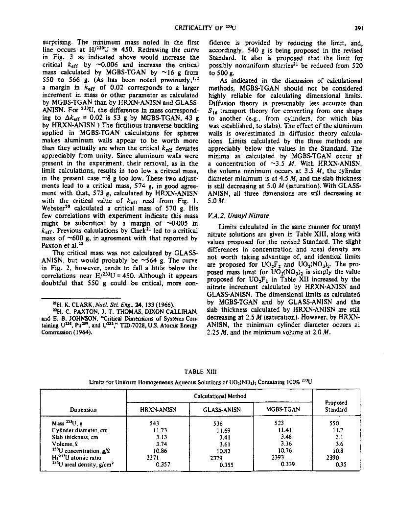
CRITICALITY OF ‘=LJ 391
few correlations with experiment indicate this mass
surprising. The minimum mass noted in the first line occurs at Hl13jU or 450. Redrawing the curve in Fig. 3 as indicated above would increase the critical &ff by -0.006 and increase the critical mass calculated by MGBS-TGAN by -16 g from 550 to 566 gD (As has been noted previously,1*2 a margin in keff of 0.02 corresponds to a larger increment in mass or other parameter as calculated by MGBS-TGAN than by HRXN-ANISN and CLASS- ANISN. For 233U the difference in mass correspond- ing to A&f = OIO2 is 53 g by MGBS=TGAN,43 g by HRXN-ANISN.) The fictitious transverse buckiing applied in MGBS-TGAN calculations for spheres makes aluminum walls appear to be worth more than they actually are when the critical keff deviates appreciably from unity. Since aluminum walls were present in the experiment, their removal, as in the limit calculations, results in too low a critical mass, in the present case -8 g too low. These two adjust- ments lead to a critical mass, 574 g, in good agree- ment with that, 573 g, calculated by HRXN-ANISN with the critical value of keff read from Fig. 1. Webster2’ calculated a critical mass of 570 g. His
fidence is provided by reducing the limit, and, accordingly, 540 g is being proposed in the revised Standard. It also is proposed that the limit for possibly nonuniform slurries21 be reduced from 520 to 500 g.
As indicated in the discussion of calculational methods, MGBS-TGAN should not be considered highly reliable for calculating dimensional limits. Diffusion theory is presumably less accurate than St6 transport theory for converting from one shape to another (e.g., from cylinders, for which bias was established, to slabs). The effect of the aluminum walls is overestimated in diffusion theory calcula- tions. Limits calculated by the three methods are appreciably below the values in the Standard. The minima as calculated by MGBS-TGAN occur at a concentration of -3.5 M. With HRXN-ANISN, the volume minimum occurs at 3-5 M, the cylinder diameter minimum is at 4.5 M, and the slab thickness is still decreasing at 5.0 M (saturation). With GLASS- ANISN, all three dimensions are still decreasing at 5.0M.
might be subcritical by a margin of -0.005 in k eff. Previous calculations by Clark” led to a critical mass of -600 g, in agreement with that reported by Paxton et al.22
The critical mass was not calculated by GLASS- ANISN, but would probably be -564 g. The cume in Fig. 2, however, tends to fall a little below the correlations near H/233U = 450. Although it appears doubtful that 550 g could be critical, more con-
Limits calculated in the same manner for uranyl nitrate solutions are given in Table XIII, along with
VlA.2. UranylNitrate
values proposed for the revised Standard. The slight differences in concentration and areal density are not worth taking advantage of, and identical limits are proposed for U02F, and U02(NO$2. The pro- posed mass limit for U02(NOs)2 is simply the value proposed for U02F2 in Table XII increased by the nitrate increment calculated by HRXN-ANISN and GLASS-ANISN. The dimensional limits as calduiated
21H K CLARK, Nucl. sci. Eng., 24,133 (1966). by MGBS-TGAN and by GLASS-ANISN and the “H’ C= PAXTON J T. THOMAS DIXON CALLIHAN
and E. b. JOHNSON,’ %iticpI Dim&ions of Systems Con: slab thickness calculated by HRXN-ANISN are still decreasing at 2.5 M (saturation). However, by HRXN-
taining P, Pun9, and Ua3,” TID-7028, U.S. Atomic Energy ANISN, the minimum cylinder diameter occurs a6: Commission ( 1964). 2.25 M, and the minimum volume at 2.0 M.
TABLE XIII
Limits for Uniform Homogeneous Aqueous Solutions of U02(NO& Containing 100% n3U
Dimension
Mass u3U, g 543 536 523 550 Cylinder diameter, cm 11.73 11.69 11.41 11.7 Slab thickness, cm 3.13 3.41 3.48 3.1 Volume, P 3.74 3.61 3.36 3.6 233U concentration, g/Q 10.86 10.82 10.76 10.8 H/233U atomic ratio 2371 2379 I 2393 2390 ‘j3U areai density, g/cm2 0.357 0.355 0.339 0.35
Calculational Method
HRXN-ANlSN I GLASS-ANISN I MGBS-TGAN Proposed Standard

392 CLARK
TABLE XIV Limits Calculated for Metal and Dry Oxide* Containing 1009G a3U
I Calculational Method
Present ‘I Proposed Material Dimension’ Standard HRXN-ANISN GLASS-ANISN Standard
Metal M 6.7 6.95 6.05 60 D 4.6 4.90 4.53 4:s T 0.54 0.61 0.38 0.38
uo 2 M w-e 13.05 10.90 10.9 MO -a- 14.84 12.39 12.4 D --w 7.89 7.20 7.2 T --- 1.28 0.80 0.80
U308 M a-- 18.57 15.10 15.1 MO --A 21.97 17.86 17.8 D --- 9.94 8.98 9.0 T --w 1.79 1.12 1.1
uo 3 M e-w 21.89 17.56 17.5 MO -w- 26.40 21.17 21.1 D --- 11.07 9.95 9.9 T M-m 2.09 1.31 1.3
*Densities of U U02, Up,, and W03 may not exceed 18.65, 10.76,8.15, and 7.16 g/cm’, respectively. ‘M = mass of 2QU in kilograms, MO = mass of uranium oxide in kilograms, D = cylinder diameter in centimetres, and T = siab
thickness in centimetres.
TABLE XV
Limits Calculated for Moist * Oxides Containing 100% =U .
Full Densit yb Half-DensityC ,
Proposed Proposed Oxide Dimensionsa HRXN-ANISN GLASS-ANISN Standard HRXN-ANISN GLASSANISN Standard
uo2 M 13.00 10.13 1o.i 32.69 23.40 23.4 MO 1501 11.72 11.7 37.75 27.02 27.0 D 8.35 7.44 7.2 14.26 12.31 11.9 T 1.42 0.87 0.80 2.84 1.74 1.6
U308 M 17.62 13.38 13.4 44.06 30.50 30.5 MO 21.17 16.07 16.0 52.92 36.64 36.6 D 10.22 9.01 9.0 17.48 14.91 14.8 T 1.90 1.17 1.1 3.80 2.34 2.2
w M 20.39 15.26 15.2 50.93 34.68 34.7 MO 24.96 18.69 18.7 62.35 42.46 42.4 D
. 11.26 9.88 9.9 19.28 16.36 16.3
T 2.19 1.34 1.3 4.37 2.68 2.6 i
*The oxide contains 1.5 wt% water. aM = mass of 233U in kilograms, MO = mass of moist oxide in kilograms, D = cylinder diameter in centimetres, and T = slab
thickness in centimetres. bFull density of moist oxide is based on the assumption that its volume is the sum of the volume of dry oxide (at physical
densities of 10.76, 8.15, and 7.16 g/cm3, respectively, for U02, U,08, and U03) and the volume of water at 20°C with a density of 0.99823 g/cm3.
The above densities of oxide and water are halved, i.c., the moist oxide contains SW voids.

CRITICALITY OF ‘=U 393
Limits for HRXN-ANISN
V:B. Metul and Oxides
metal and dry oxide, and GLASS-ANISN,
calculated by are given in
Table XIV. These limits correspond to a keff value 0.02 below the critical value selected by analogy with z3sU and plutonium experiments, The metal or oxide cores were surrounded by 2O-cm-thick water at 20°C. The quadrature was SId, the small difference between S1, and S, being ignored. Since the larger change in the critical ke~f between bare and water-reflected systems was selected in Sec. IVB, a margin of 0.02 was considered sufficient tO assure subcriticality for metal. It was also considered suffi- cient for oxides since experiments with plutonium oxide indicate no lower critical k,ff for oxide than for metal.’ The limits in the present Standard are based on calculations by Roach and Smithz3 and are values they calculate from Hansen-Roach cross sections by S8 at k eff (uncorrected for bias) = 0.97. Not surprisingly, they are consistent with the HRXN-ANISN results by Sib at keff = 0.977. The agreement between the HRXN-ANISN and the GLASS-ANISN calculations is poorer for 233U than it was for 235U or 23?u and may indicate the selection of too low a critical value of keff for water-reflected 233U systems. However, in the absence of a definitive experiment or of a compelling reason for increasing the critical value, the prudent course to follow is to base the proposed limits on the GLASS-ANISN calculations.
Limits, calculated similarly, for moist oxides at full and half-density are given in Table XV. The moisture is limited to 1.5 wt% as for 23sU and 23?Pu. Volumes of moisture and oxide are assumed to be additive. Comparison of Tables XIV and *XV shows that moisture reduces the limiting mass of uranium for all oxides as calculated by either method, but the only dimension reduced is the cylinder diameter of
w. H. ROACH and D. R. SMITH, “Estimate of Maxi- mum Subcritical IXmensions of Single Fissile Metal Units,” ORNL-CDC-3, Oak Ridge National Laboratory (1967).
U03 as calculated by GLASS-ANISN. The proposed limits in Table XV are the lower of the dry and moist values. (Although not tabulated here, calculations were also made for dry half-density oxides and were consistent with other results.)
APPENDIX
TO gain a better understanding of the application of one-dimensional m e thods to twodimensional problems, i.e., finite cylinders, some critical, mathe- matical benchmark cases were calculated by the TWOTRAN code24 and were analyzed in various ways by one-dimensional methods. The cases selected were cylinders of 233U01F2 solution containing 400 g 233U/J2 with various height-to-diameter ratios, and reflectkd by I5-cm-thick water. In some cases, an aluminum wall was interposed. To limit computer time, the calculations were made with two energy groups, isotropic scattering, and no upscatter. The macroscopic cross sections were generated by GLASS from ENDF/B-IV cross sections and are given in Table A.I. Calculations were made with a uniform mesh in each material, using 0.2 times the number of radial intervals and 0.8 times the number of axial intervals prescribed in empirical formulas.2s Typically, the number of mesh volumes was -600. Quadrature was Sib to give an accurate solution. In addition, ANISN was used to calculate the in- finite slab. Calculations have shown a disagreement between TWOTRAN and ANISN for the infinite cylinder corresponding to -1% in k,ff with only
%. D. LATHROP and F. W. BRINKLEY, ‘TWOTRAN- II: An Interfaced, Exportable Version of the TWOTRAN Code for Two-Dimensional Transport,” LA-48489MS, Los Alamos National Laboratory ( 1973).
2SR. C. SOLTESZ et al., “Nuclear Rocket Shielding Methods Modification, Updating, and Input Data Preparation, Vol. IV, One Dimensional Discrete Ordinates Transport Tech- nique. Final Progress Report,” WANLPR(LL)-034, Westing house Astronuciear Laboratory (1970).
TABLE A.1
TwoGroup Cross Sections \ r 9
Material Group &, cm” I+, cm” C, cm-’ q,,), cm-’ &pg+l) v cm -1 r 1 I
Uranium solution 1 0.020794 0.044029 0.267053 0.222033 0.024226 2 0.36282 1 0.80035 1 1.39704 1.0342 1 0
Water 1 0.000458 0 0.255747 0.204324 0.050965 2 0.018972 0 2.23097 2.21200 0
Aluminum 1 0.000419 0 0.135803 0.135163 0.00022 1 2 0.011993 0 0.089297 0.077304 0
b

394 CLARK
S, quadrature; agreement is much better with S16. The central processing unit time required for the calculation of a cylinder was -20 min on an IBM Model 195. Results are given in Table A.11. The code indicated that the problems were converged in all cases, despite the specified inner iteration limit of 10 always being reached in the thermal group.
(The failure of keff to be exactly unity for the infinite cylinder in Table A.111 represents the slight discrepancy between ANISN and TWOTRAN with & quadrature.) Thus, linear extrapolation of ktff as a function of axial buckling should be a valid
The first method applied to these benchmarks
procedure for obtaining the critical value of keff
was ANISN-SPBL with the PO cross sections of Table A.1 and with S16 quadrature. In this approach,
for an infinite cylinder and hence of the bias of
keff is calculated for each dimension of a finite cylinder with the other dimension assumed to be infinite. Geometric bucklings are calculated (by B,) corresponding to each value of keff and are added to obtain the total geometric buckling. The value of keff corresponding to this buckling is then cal- culated (again by B,). Table A.111 gives results ob- tained by this method for the benchmark cases of Table A.11. The method overestimates kcff for finite cylinders, but the overestimation decreases as the infinite cylinder is approached (i.e., as the axial buckling approaches zero) and kcff then becomes very nearly a linear function of the axial buckling.
TABLE A.111
Calculation of the Cylinders of Table A.11 by the ANISN-SPBL Codes
Total keff
1.0000 1.0000
- Axial
Height-to- Wall’ Buckling almeter Thickness, i3;, Radialb -Axialb
Ratio cm cm-l ko kH 0 None 0.04698 2.1644 1 .oooo
0.16 0.04698 2.1644 1 .oooo
0.25 None 0.02604 1 SS45 1.2903 1.0705
0.5 None 0.0 1859 1.3722 1.4494 Lb719 0.16 0.0 1839 1.3736 1.4544 1.0767
1.0 None 0.01182 1.2212 1 A402 1.0170
2.0 None 0.0064 1 1.1118 1.8403 1.0340 0.16 0.0063 1 1.1146 1.8445 1.0374
4.0 None 0.00284 1.0462 2.0066 LOl48
0 None 0. 0.9995 2.1644 0.9995 0.16 0 0.9994 2.1644 0.9994
qhe wall material was aluminum.
. bThese are values of k for cylinders with one dimension assumed
to be infrnlty*
the calculational method. An additional test of this thesis was made by repeating the ANISN-SPBL analysis of the benchmarks of Table A.11, but with
TABLE A.11 Dimensions of Critical Benchmark Cylinders Calculated
by Two-Dimensional Codes
Height-to- Diameter
Ratio
Ob
0.25
0.50
1.0
2.0
4.0 00
7
Walla Diameter, Height, Thickness, cm
NON 00 2.73126 0.16 Qo 2.75 136
None 25 9620 6.4905
None 19.1352 9.5676 0.16 19.2670 9.6335
None 14.9304 14.9304
None 12.4237 24.8474 0.16 i2.52 12 25.0424
None 11.0869 44.3476 None 10.2008 00 0.16 10.2496 00
Hansen-Roach cross sections (16 groups, PI scat- tering.) The cylinders contained in aluminum and the cylinders with height-to-diameter ratios of zero and 0.25 were omitted. Results are given in Table AJV, and again kcff is nearly linear with Bi at small Bft albeit with slightly larger slope. The low values of keff are consistent with the finding that, at high concentrations of 233U, ENDF/B-IV cross
J
TABLE AJV Calculation of the Cylinders of Table A.11 by the ANISN-SPBL
Codes with Hansen-Roach Cross Sections
Height-to- Diameter
Ratio
0.5
! .o
2.0
$9 Rad iala cm” b
0.01924 I .2955
0.01213 1.1282
0.0065 I 1.0043
0.00286 0.9292
0 0.8756
Axiala hi
1.3768
1.5762
1.7757
1.9337 a--
kff 1
0.9604
0.9429
0.9159
0.8935
0.8756 The wall material was aluminum. *he infinite slab was calculated by the ANISN code; These are values of k for cylinders with one dimension
other cylinders were calculated by TWOTRAN. assumed to be infinity.

CRITICALITY OF ‘=IJ 395
TABLE A.V Calculation of the Cylinders of Table A.11 by Critical
Transverse Buckling Implemented by ANISN
Hcight-to- Diameter
Ratio
0
0.25
0.50
1 .OO
2 .oo
4.00
Qo
Walla Thickness,
cm
None 0.16
None
None 0.16
None
None 0.16 None
None 0.16
2b Bh* cmg2 b!ff
0.04698 1 BOO0 0.04698 1.0000 0.03065 0.9982
0.02261 0.9980 0.02363 0.98 13
0.01440 0.9988
0.00756 1.0001 0.00785 0.9937
0.00318 1.0003
0 * 0.9995 0 0.9994
The wall material was aluminum. bliere, Bi is the calculated critical buckling minus the
calculated critical radial buckling.
sections underestimate the critical mass, whereas Hansen-Roach cross sections overestimate it.
Another method of analyzing two-dimensional critical bodies by one-dimensional codes, the one incorporated in TGAN, is to search for the critical transverse buckling corresponding to each critical dimension. The geometric buckling of a finite cylin- der is then $ = 28: - E;- E& The term Bf is the critical buckling calculated from composition and cross sections, and B: and Bi are, respectively, the transverse (radial) buckling calculated to make a slab with thickness equal to the cylinder height critical and the transverse (axial) buckling calculated to make the cylinder critical. The value of keff calculated for the critical finite cylinder corresponds to this geometric buckling. This method, imple- mented by ANISN with the cross sections of Table A.1, was applied to the benchmarks26 of Table A.11. The transverse leakage is calculated as DB& and is treated as an equivalent absorption. With the dif-
261n similar calculations (Ref. 27), it was found that ke caiculated by ANISN at the critical transverse buckling deter- mined by ANISN deviated somewhat from unity, but no such discrepancies were found in the present case.
27H. K. CLARK, “Snake Bites from Code Misuse and Overuse,” Proc. Topl. Mfg. Nuclear Oiticality Safety, El Paso, Texas, April 8-10, 1980, SAND-80-1675, Sandia National Laboratories (1980).
TABLE A.VI
Calculation of the Cylinders of Table A.11 by the TGAN Code
I Height-to- Wall’ k;ff Diameter Thickness,
Ratio cm GLASS Code MGBS Code
0 None 1.0098 1.0457 0.16 1 .oO93 1.0593
0.50 None 0.9964 1.0726 0.16 0.9784 1.0498
1.00 None 0.9968 1.0729
2.00 None 0.9990 1.0722 0.16 0.9922 1.0605
4.00 None 1.0008 1.0712
00 None 1.0014 1.0699 0.16 1.0017 1.0648
qhe wall material is aluminum.
fusion coefficient, D, equal to l/3&,, poor results were obtained (k,ff 2 0.95). Much better results were obtained with
D =L-AlL--l C B7 tan-l (E/Z) 1 ’
the correct transport theory expression for isotropic scattering. Results of the calculations are given in Table A.V. With only water reflection, the method gives very good results for the finite cylinders, but with the aluminum wall interposed, keff is too low due to streaming in the aluminum resulting from the assumption of separability of the neutron flux.
The same method as implemented by TGAN with diffusion theory constants was applied to the benchmarks. In one case, the constants were derived by GLASS; in the other, by MGBS. Results are given in Table A.VI. The results from the diffusion theory calculations agree fairly well with those from transport theory. The large values of keff calculated with MGBS cross sections are consistent with the biases found in the correlations with experiment. Again, the calculated effect of the aluminum wall is too large.
ACKNOWLEDGMENT
The information contained in this article was developed during the course of work sponsored by the U.S. Department of Energy under contract with the E. 1. du Pont de Nemours and Company.