Embed Size (px)
Citation preview

DEPARTMENT OF COMPUTER SCIENCE AND ENGINEERING
Name of the Subject : Computer Networks
Subject code : CS8591
Regulation : 2017
UNIT I - INTRODUCTION AND PHYSICAL LAYER
NETWORKS
A network is a set of devices (often referred to as nodes) connected by communication links.
A node can be a computer, printer, or any other device capable of sending and/or receiving
data generated by other nodes on the network.
Network Criteria
A network must be able to meet a certain number of criteria. The most important of these are
performance, reliability, and security
Performance
Performance can be measured in many ways, including transit time and response time.
Transit time is the amount of time required for a message to travel from one device to
another.
Response time is the elapsed time between an inquiry and a response.
Performance is often evaluated by two networking metrics: throughput and delay. We
often need more throughput and less delay.
Reliability
Network reliability is measured by the frequency of failure, the time it takes a link to recover
from a failure.
Security
Network security issues include protecting data from unauthorized access, protecting data
from damage and development, and implementing policies and procedures for recovery from
breaches and data losses.
Physical Structures
Type ofConnection
A network is two or more devices connected through links. A link is a communications
pathway that transfers data from one device to another.
Point-to-Point
A point-to-point connection provides a dedicated link between two devices. The entire
capacity of the link is reserved for transmission between those two devices.
Most point-to-point connections use an actual length of wire or cable to connect the two ends,
but other options, such as microwave or satellite links, are also possible.

Multipoint
A multipoint (also called multidrop) connection is one in which more than two specific
devices share a single link.
In a multipoint environment, the capacity of the channel is shared, either spatially or
temporally.
Ifseveral devices can use the link simultaneously, it is a spatially shared connection. If
users must take turns, it is a timeshared connection.
Physical Topology
The term physical topology refers to the way in which a network is laid out physically.: 1\vo
or more devices connect to a link; two or more links form a topology.
There are four basic topologies possible: mesh, star, bus, and ring.

Mesh
In a mesh topology, every device has a dedicated point-to-point link to every other
device. The term dedicated means that the link carries traffic only between the two
devices it connects.
n(n - 1) physical links are needed to connect n nodes.
if each physical link allows communication in both directions (duplex mode), we can
divide the number of links by 2. ie) we need n(n -1) /2 duplex links
Advantages
The use of dedicated links guarantees that each connection can carry its own data
load, thus eliminating the traffic problems.
A mesh topology is robust. If one link becomes unusable, it does not affect the entire
system.
Privacy or security. When every message travels along a dedicated line, only the
intended recipient sees it.
Disadvantages
every device must be connected to every other device, installation and
reconnection are difficult.
Bulk of the wiring can be greater than the available space.
The hardware required to connect each link (I/O ports and cable) can be
prohibitively expensive
Application
One practical example of a mesh topology is the connection of telephone regional offices in
which each regional office needs to be connected to every other regional office.
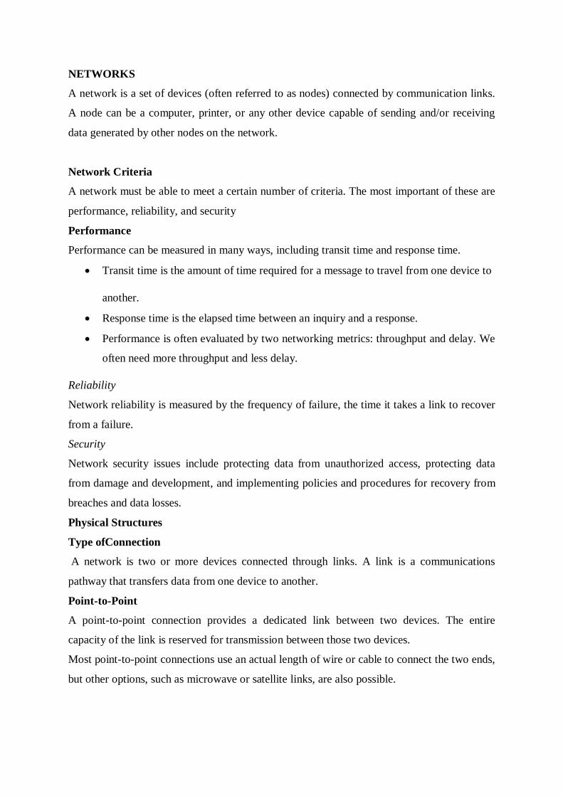
Star
In a star topology, each device has a dedicated point-to-point link only to a central
controller, usually called a hub. The devices are not directly linked to one another.
A star topology does not allow direct traffic between devices.
The controller acts as an exchange: If one device wants to send data to another, it
sends the data to the controller, which then relays the data to the other connected
device.
Advantages
A star topology is less expensive than a mesh topology
Robustness.-If one link fails, only that link is affected. All other links remain active.
Disadvantage
star topology is the dependency of the whole topology on one single point, the hub. If
the hub goes down, the whole system is dead.
The star topology is used in local-area networks (LANs), High-speed LANs
often use a star topology with a central hub.
Bus Topology
A bus topology, on the other hand, is multipoint. One long cable acts as a backbone to
link all the devices in a network

Nodes are connected to the bus cable by drop lines and taps.
A drop line is a connection running between the device and the main cable
Advantages
bus topology include ease of installation.
Disadvantages
Itincludes difficult reconnection and fault isolation.
fault or break in the bus cable stops all transmission.even between devices on the
same side of the problem. The damaged area reflects signals back in the direction of
origin, creating noise in both directions.
Adding new devices may therefore require modification or replacement of the
backbone.
Bus topology was the one of the first topologies used in the design of early
localarea networks. Ethernet LANs can use a bus topology.
Ring Topology
In a ring topology, each device has a dedicated point-to-point connection with only
the two devices on either side of it.
A signal is passed along the ring in one direction, from device to device, until it
reaches its destination.
Each device in the ring incorporates a repeater. When a device receives a signal
intended for another device, its repeater regenerates the bits and passes them along.

Advantages
A ring is relatively easy to install and reconfigure. Each device is linked to only
its immediate neighbours.
To add or delete a device requires changing only two connections.
Fault isolation is simplified. (Generally in a ring, a signal is circulating at all
times. If one device does not receive a signal within a specified period, it can
issue an alarm. The alarm alerts the network operator to the problem and its
location)
Disadvantages
In a simple ring, a break in the ring (such as a disabled station) can disable
the entire network(This weakness can be solved by using a dual ring or a
switch capable of closing off the break)
Hybrid Topology
A network can be hybrid. For example, we can have a main star topology with each branch
connecting several stations in a bus topology.

Network Types
Local Area Network(LAN)
A Local area Network (LAN) is usually privately owned and connects
some hosts in a single office, building or campus.
Depending upon the need of the organization the LAN can be simple or
complex.
Each host in the LAN has a identifier ,an address, uniquely defines the
host in the LAN.
A packet sent by a host to another host carries both source host and
destination host address .
LAN size is limited to a few kilometres.
In past all hosts in the network connected through a common cable , which
meant that a packet sent from one host to another was received by all the
hosts. The indented recipient kept the packet others dropped the packet.
Now most of the LAN use a smart connecting switch which is able to
recognise the destination address and guide the packet to sent to the
destination node.

Wide Area Network
A wide area network (WAN) is also an interconnection of devices capable of
communication.
A WAN has a wider geographical span, spanning a town, a state, a country, or even
the world.
A LAN interconnects hosts; a WAN interconnects connecting devices such as
switches, routers, or modems.
A LAN is normally privately owned by the organization that uses it; a WAN is
normally created and run by communication companies and leased by an organization
that uses it.
Point-to-Point WAN
A point-to-point WAN is a network that connects two communicating devices through a
transmission media (cable or air).
Switched WAN

A switched WAN is a network with more than two ends.
Switched WAN is a combination of several point-to-point WANs that are connected
by switches.
Internetwork
When two or more networks are connected, they make an internetwork, or internet.
Switching
An internet is a switched network in which a switch connects at least two links together. A
switch needs to forward data from a network to another network when required.
The two most common types of switched networks are circuit-switched and packet-switched
networks.
Circuit-Switched Network
In a circuit-switched network, a dedicated connection, called a circuit, is always available
between the two end systems; the switch can only make it active or inactive.

A circuit-switched network is efficient only when it is working at its full capacity;
most of the time, it is inefficient because it is working at partial capacity. (eg: site are
talking with four people at the other site; the capacity of the thick line is fully used. In
the second case, only one telephone set at one side is connected to a telephone set at
the other side; only one-fourth of the capacity of the thick line is used).
Packet-Switched Network
In a computer network, the communication between the two ends is done in blocks of
data called packets.
A router in a packet-switched network has a queue that can store and forward the
packet.
If only two computers (one at each site) need to communicate with each other, there is
no waiting for the packets. However, if packets arrive at one router when the thick
line is already working at its full capacity, the packets should be stored and forwarded
in the order they arrived.
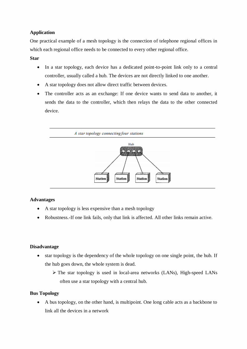
The Internet
An internet is two or more networks that can communicate with each other.
The most notable internet is called the Internet (uppercase I ), and is composed of
thousands of interconnected networks.
At the top level, the backbones are large networks owned by some communication
companies such as Sprint, Verizon (MCI), AT&T, and NTT. The backbone networks
are connected through some complex switching systems, called peering points.
At the second level, there are smaller networks, called provider networks, that use the
services of the backbones for a fee. The provider networks are connected to
backbones and sometimes to other provider networks.
The customer networks are networks at the edge of the Internet that actually use the
services provided by the Internet. They pay fees to provider networks for receiving
services.
Backbones and provider networks are also called Internet Service Providers (ISPs).
The backbones are often referred to as international ISPs; the provider networks are
often referred to as national or regional ISPs.
Accessing the Internet
The Internet today is an internetwork that allows any user to become part of it. The user,
however, needs to be physically connected to an ISP. The physical connection is normally
done through a point-to-point WAN
❑ Dial-up service.
This service add to the telephone line a modem that converts data to voice.
The software installed on the computer dials the ISP and imitates making a telephone
connection.
The dial-up service is very slow, and when the line is used for Internet connection, it
cannot be used for telephone (voice) connection.
It is only useful for small residences.
❑ DSL Service.
The DSL service also allows the line to be used simultaneously for voice and data
communication.
Using Cable Networks
The cable companies have been upgrading their cable networks and connecting to the
Internet.
A residence or a small business can be connected to the Internet by using this service.
It provides a higher speed connection, but the speed varies depending on the number
of neighbours that use the same cable.
Using Wireless Networks
In wireless WAN access, a household or a small business can be connected to the Internet
through a wireless WAN.
Direct Connection to the Internet
A large organization or a large corporation can itself become a local ISP and be
connected to the Internet.
This can be done if the organization or the corporation leases a high-speed WAN from
a carrier provider and connects itself to a regional ISP.
For example, a large university with several campuses can create an internetwork and
then connect the internetwork to the Internet.

PROTOCOL LAYERING
A protocol defines the rules that both the sender and receiver and all intermediate
devices need to follow to be able to communicate effectively.
When communication is simple, we may need only one simple protocol;
when the communication is complex, we may need to divide the task between
different layers, in which case we need a protocol at each layer, or protocol layering
TCP/IP PROTOCOL SUITE
TCP/IP is a protocol suite (a set of protocols organized in different layers) used in the
Internet today.
It is a hierarchical protocol made up of interactive modules, each of which provides a
specific functionality.
The term hierarchical means that each upper level protocol is supported by the
services provided by one or more lower level protocols.
Layered Architecture

TCP/IP PROTOCOL SUITE:
The TCPIIP protocol suite was developed prior to the OSI model. Theoriginal TCP/IP
protocol suite was defined as having four layers: host-to-network,internet, transport,
and application.
TCP/IP is a hierarchical protocol made up of interactive modules, each of
whichprovides a specific functionality; however, the modules are not necessarily
interdependent.

Fig: TCP/IP and OSI model.
TCP/IP is a hierarchical protocol made up of interactive modules, each of
whichprovides a specific functionality; however, the modules are not necessarily
interdependent.
TCP/IP protocol suite contain relatively independent protocols thatcan be mixed and
matched depending on the needs of the system. The term hierarchicalmeans that each
upper-level protocol is supported by one or more lower-levelprotocols.
At the transport layer, TCP/IP defines three protocols: Transmission ControlProtocol
(TCP), User Datagram Protocol (UDP), and Stream Control TransmissionProtocol
(SCTP).
At the network layer, the main protocol defined by TCP/IP is the Internetworking
Protocol (IP)
Physical and Data Link Layers
At the physical and data link layers, TCPIIP does not define any specific protocol.
Itsupports all the standard and proprietary protocols.
Network Layer
At the network layer (or, more accurately, the internetwork layer), TCP/IP
supportsthe Internetworking Protocol. IP uses four supporting protocols: ARP,RARP,
ICMP, and IGMP.

Internetworking Protocol (IP)
The Internetworking Protocol (IP) is the transmission mechanism used by the TCP/IP
protocols. It is an unreliable and connectionless protocol-a best-effort delivery
service.
The term best effort means that IP provides no error checking or tracking.
IP transports data in packets called datagrams, each of which is transported
separately.Datagrams can travel along different routes and can arrive out of sequence
or beduplicated.
IP does not keep track of the routes and has no facility for reordering datagramsonce
they arrive at their destination.
Address Resolution Protocol
The Address Resolution Protocol (ARP) is used to associate a logical address with
aphysical address.ARP is used to find the physical address of the node when its
Internetaddress is known.
Reverse Address Resolution Protocol
The Reverse Address Resolution Protocol (RARP) allows a host to discover its
Internetaddress when it knows only its physical address.
Internet Control Message Protocol
The Internet Control Message Protocol (ICMP) is a mechanism used by hosts
andgateways to send notification of datagram problems back to the sender. ICMP
sendsquery and error reporting messages.
Internet Group Message Protocol
The Internet Group Message Protocol (IGMP) is used to facilitate the
simultaneoustransmission of a message to a group of recipients.
Transport Layer
Transport layer was represented in TCP/IP by two protocols: TCP andUDP. IP is a
host-to-host protocol, meaning that it can deliver a packet from onephysical device to
another.
UDP and TCP are transport level protocols responsiblefor delivery of a message from
a process (running program) to another process.
User Datagram Protocol

The User Datagram Protocol (UDP) is the simpler of the two standard TCP/IP
transportprotocols. It is a process-to-process protocol that adds only port addresses,
checksumerror control, and length information to the data from the upper layer.
Transmission Control Protocol
The Transmission Control Protocol (TCP) provides full transport-layer services
toapplications. TCP is a reliable stream transport protocol. The term stream, means
connection-oriented:
TCP divides a stream of data into smallerunits called segments. Each segment
includes a sequence number for reordering afterreceipt, together with an
acknowledgment number for the segments received.
Stream Control Transmission Protocol
The Stream Control Transmission Protocol (SCTP) provides support for
newerapplications such as voice over the Internet.
Application Layer
The application layer in TCPIIP is equivalent to the combined session,
presentation,and application layers in the OSI model. Many protocols are defined at
this layer.
THE OSI MODEL:
The OSI model is not a protocol; it is a model for understanding anddesigning a
network architecture that is flexible, robust, and interoperable.
The OSI model is a layered framework for the design of network systems thatallows
communication between all types of computer systems. It consists of seven
separatebut related layers.
Layered Architecture:
The OSI model is composed of seven ordered layers: physical (layer 1), data link
(layer 2),network (layer 3), transport (layer 4), session (layer 5), presentation (layer
6), andapplication (layer 7).
Peer-to-Peer Processes:
At the physical layer, communication is direct: In Figure 2.3, device A sends a
streamof bits to device B (through intermediate nodes). At the higher layers, however,
communicationmust move down through the layers on device A, over to device B,
and then back up through the layers.
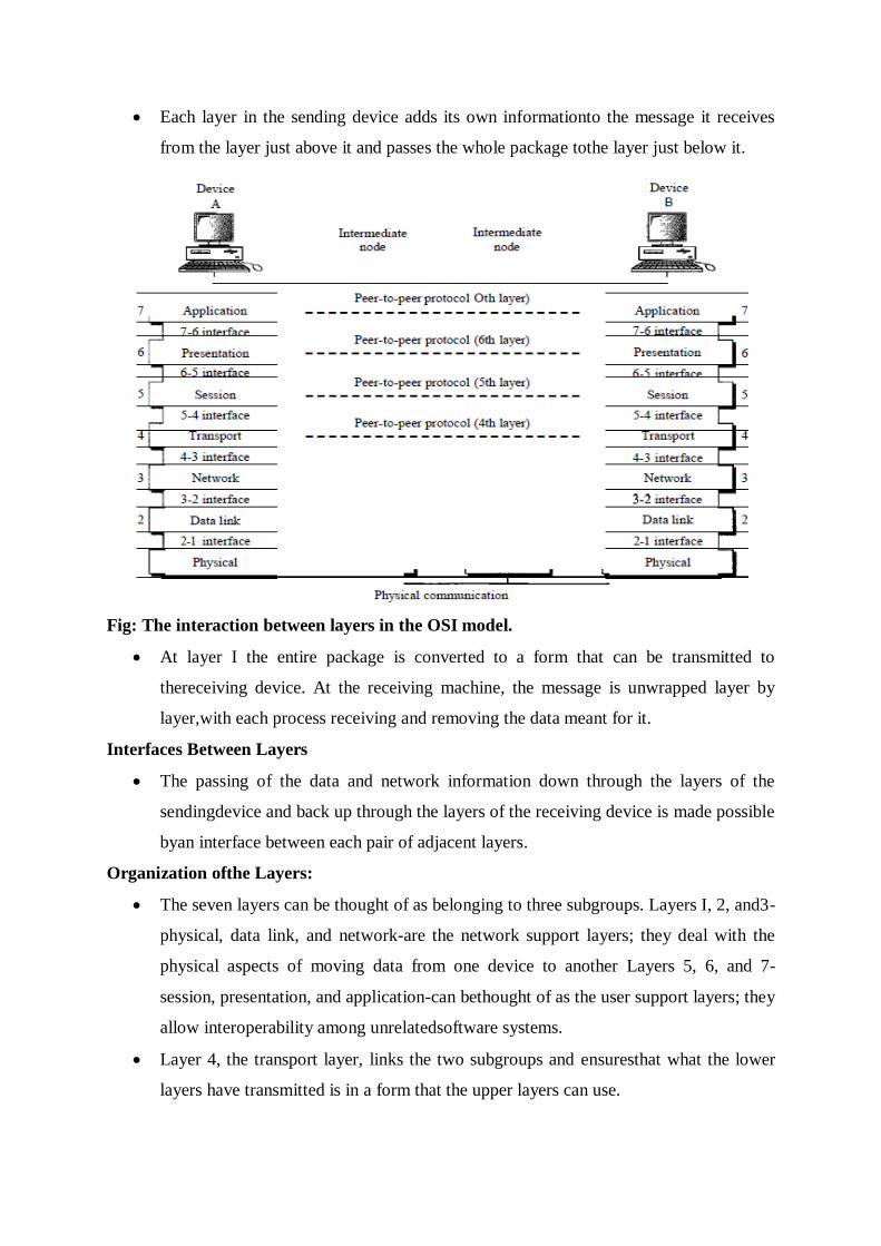
Each layer in the sending device adds its own informationto the message it receives
from the layer just above it and passes the whole package tothe layer just below it.
Fig: The interaction between layers in the OSI model.
At layer I the entire package is converted to a form that can be transmitted to
thereceiving device. At the receiving machine, the message is unwrapped layer by
layer,with each process receiving and removing the data meant for it.
Interfaces Between Layers
The passing of the data and network information down through the layers of the
sendingdevice and back up through the layers of the receiving device is made possible
byan interface between each pair of adjacent layers.
Organization ofthe Layers:
The seven layers can be thought of as belonging to three subgroups. Layers I, 2, and3-
physical, data link, and network-are the network support layers; they deal with the
physical aspects of moving data from one device to another Layers 5, 6, and 7-
session, presentation, and application-can bethought of as the user support layers; they
allow interoperability among unrelatedsoftware systems.
Layer 4, the transport layer, links the two subgroups and ensuresthat what the lower
layers have transmitted is in a form that the upper layers can use.

The upper OSI layers are almost always implemented in software; lower layers are
acombination of hardware and software, except for the physical layer, which is
mostlyhardware.
At each layer, a header, or possibly a trailer, can be added to the data
unit.Commonly, the trailer is added only at layer 2. When the formatted data unit
passesthrough the physical layer (layer 1), it is changed into an electromagnetic signal
andtransported along a physical link.
Upon reaching its destination, the signal passes into layer 1 and is transformedback
into digital form. The data units then move back up through the OSI layers.
Aseach block of data reaches the next higher layer, the headers and trailers attached to
it atthe corresponding sending layer are removed, and actions appropriate to that layer
aretaken.
By the time it reaches layer 7, the message is again in a form appropriate to
theapplication and is made available to the recipient.
Fig: An exchange using the OSI model.
LAYERS IN THE OSI MODEL:
Physical Layer The physical layer coordinates the functions required to carry a bit stream over a
physicalmedium. It deals with the mechanical and electrical specifications of the
interface andtransmission medium.

The physical layer is responsible for movements ofindividual bits from one hop
(node) to the next.
The physical layer is also concerned with the following:
Physical characteristics of interfaces and medium.
The physical layer definesthe characteristics of the interface between the
devices and the transmissionmedium. It also defines the type of transmission medium.
Representation of bits.
The physical layer data consists of a stream of bits(sequence of 0s or 1s) with
no interpretation. To be transmitted, bits must beencoded into signals--electrical or
optical. The physical layer defines the type of encoding (how 0s and 1s are changed to
signals).
Data rate.
The transmission rate-the number of bits sent each second-is alsodefined by
the physical layer.
Synchronization of bits.
The sender and receiver not only must use the same bitrate but also must be
synchronized at the bit level.
Line configuration.
The physical layer is concerned with the connection ofdevices to the media. In
a point-to-point configuration, two devices are connectedthrough a dedicated link. In
a multipoint configuration, a link is shared amongseveral devices.
Physical topology.
The physical topology defines how devices are connected tomake a network.
Devices can be connected by using a mesh topology (every deviceis connected to
every other device), a star topology (devices are connected through a central device),
a ring topology (each device is connected to the next, forming aring), a bus topology
(every device is on a common link), or a hybrid topology (thisis a combination of two
or more topologies).
Transmission mode.
The physical layer also defines the direction of transmissionbetween two
devices: simplex, half-duplex, or full-duplex. In simplex mode, onlyone device can
send; the other can only receive. The simplex mode is a one-waycommunication. In
the half-duplex mode, two devices can send and receive, butnot at the same time. In a

full-duplex (or simply duplex) mode, two devices cansend and receive at the same
time.
Data Link Layer:
Fig: Data link layer.
The data link layer is responsible for moving frames from one hop (node) to the next.
Other responsibilities of the data link layer.
Framing.
The data link layer divides the stream of bits received from the networklayer into
manageable data units called frames.
Physical addressing.
If frames are to be distributed to different systems on thenetwork, the data link layer
adds a header to the frame to define the sender and/orreceiver of the frame.
Flow control.
The data link layer imposes a flowcontrol mechanism to avoid overwhelming the
receiver.
Error control.
The data link layer adds reliability to the physical layer by addingmechanisms to
detect and retransmit damaged or lost frames.
Access control.
When two or more devices are connected to the same link, datalink layer protocols are
necessary to determine which device has control over thelink at any given time.
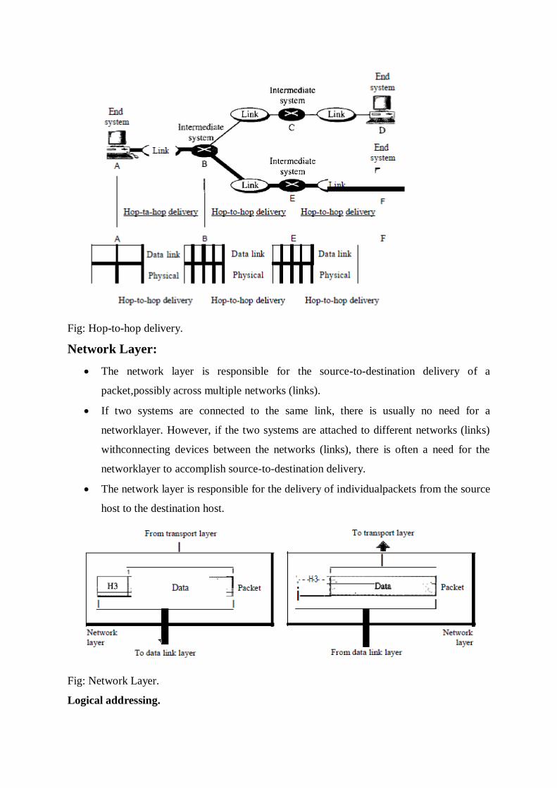
Fig: Hop-to-hop delivery.
Network Layer:
The network layer is responsible for the source-to-destination delivery of a
packet,possibly across multiple networks (links).
If two systems are connected to the same link, there is usually no need for a
networklayer. However, if the two systems are attached to different networks (links)
withconnecting devices between the networks (links), there is often a need for the
networklayer to accomplish source-to-destination delivery.
The network layer is responsible for the delivery of individualpackets from the source
host to the destination host.
Fig: Network Layer.
Logical addressing.

The physical addressing implemented by the data link layerhandles the addressing
problem locally. If a packet passes the network boundary,we need another addressing
system to help distinguish the source and destinationsystems.
Routing.
When independent networks or links are connected to create internetworks(network of
networks) or a large network, the connecting devices (called routersor switches) route
or switch the packets to their final destination.
Transport Layer:
The transport layer is responsible for process-to-process delivery of the entire
message.A process is an application program running on a host.The transport layer is
responsible for the delivery of a message from one process to another.
Fig: Transport layer
Service-point addressing.
The transportlayer header must therefore include a type of address called a service-
pointaddress (or port address).
Segmentation and reassembly.
A message is divided into transmittable segments,with each segment containing a
sequence number.
Connection control.
The transport layer can be either connectionless or connectionoriented.A
connectionless transport layer treats each segment as an independentpacket and
delivers it to the transport layer at the destination machine. A
connectionorientedtransport layer makes a connection with the transport layer at the
destinationmachine first before delivering the packets.
Flow control.

Like the data link layer, the transport layer is responsible for flowcontrol.
Error control.
The transport layer is responsible forerror control. However, error control at this layer
is performed process-to -processrather than across a single link.
Session Layer:
The services provided by the first three layers (physical, data link, and network)
arenot sufficient for some processes.
The session layer is the network dialog controller.It establishes, maintains, and
synchronizes the interaction among communicatingsystems.
The session layer is responsible for dialog control and synchronization.
Specific responsibilities
Dialog control.
The session layer allows two systems to enter into a dialog. Itallows the
communication between two processes to take place in either halfduplex(one way at a
time) or full-duplex (two ways at a time) mode.
Synchronization.
The session layer allows a process to add checkpoints, or synchronization
points, to a stream of data.
Presentation Layer
The presentation layer is concerned with the syntax and semantics of the
informationexchanged between two systems.
The presentation layer is responsible for translation, compression, and encryption.
Specific responsibilities of the presentation layer:
Translation.
The processes (running programs) in two systems are usually exchanginginformation
in the form of character strings, numbers, and so on. The informationmust be changed
to bit streams before being transmitted. Because differentcomputers use different
encoding systems, the presentation layer is responsible forinteroperability between
these different encoding methods.
The presentation layerat the sender changes the information from its sender-dependent
format into acommon format.
The presentation layer at the receiving machine changes thecommon format into its
receiver-dependent format.

Encryption.
To carry sensitive information, a system must be able to ensureprivacy.
Encryption means that the sender transforms the original information to another form
and sends the resulting message out over the network.
Decryptionreverses the original process to transform the message back to its original
form.
Compression.
Data compression reduces the number of bits contained in theinformation. Data
compression becomes particularly important in the transmissionof multimedia such as
text, audio, and video.
Application Layer:
The application layer enables the user, whether human or software, to access the
network.
It provides user interfaces and support for services such as electronic mail,remote file
access and transfer, shared database management, and other types of
distributedinformation services.
Fig: Application layer
The application layer is responsible for providing services to the user.
Network virtual terminal.
A network virtual terminal is a software version of a physical terminal, and it allows a
user to log on to a remote host.
File transfer, access, and management.

This application allows a user to accessfiles in a remote host (to make changes or read
data), to retrieve files from a remotecomputer for use in the local computer, and to
manage or control files in a remotecomputer locally.
Mail services.
This application provides the basis for e-mail forwarding andstorage.
Directory services.
This application provides distributed database sources andaccess for global
information about various objects and services.
Fig: Summary of layers.
Physical Layer Performance
One characteristic that measures network performance is bandwidth. It has two
different measuring values: bandwidth inhertz and bandwidth in bits per second.
In networking, we use the term bandwidth in two contexts.
The first, bandwidth in hertz, refers to the range of frequencies in a composite
signalor the range of frequencies that a channel can pass.
The second, bandwidth in bits per second, refers to the speed of bit transmission in
achannel or link.
Throughput:
The throughput is a measure of how fast we can actually send data through a
network.
We can calculate the throughput as
Throughput =(12,000 x10,000) / 60 =2 Mbps
Latency (Delay):

The latency or delay defines how long it takes for an entire message to
completelyarrive at the destination from the time the first bit is sent out from the
source.
We cansay that latency is made of four components: propagation time, transmission
time,queuing time and processing delay.
Latency =propagation time +transmission time +queuing time +processing delay
Propagation Time
Propagation time measures the time required for a bit to travel from the source to
thedestination. The propagation time is calculated by dividing the distance by the
propagationspeed.
Propagation time =Distance / (Propagation Speed)
Transmission Time:
The transmission time of a messagedepends on the size of the message and the
bandwidth of the channel.
Transmission time =(Message size) / Bandwidth
Queuing Time:
The third component in latency is the queuing time, the time needed for each
intermediateor end device to hold the message before it can be processed. The
queuing time isnot a fixed factor; it changes with the load imposed on the network.
When there isheavy traffic on the network, the queuing time increases.
Transmission Media
Introduction
Transmission media are actually located below the physical layer and are directly
controlled by the physical layer. We could say that transmission media belong to layer
zero.
The below figure shows the position of transmission media in relation to the physical
layer.
A transmission medium can be broadly defined as anything that can carry
information from a source to a destination.
In data communications the definition of the information and the transmission
medium is more specific.
The transmission medium is usually free space, metallic cable, or fiber-optic
cable. The information is usually a signal that is the result of a conversion of
data from another form.
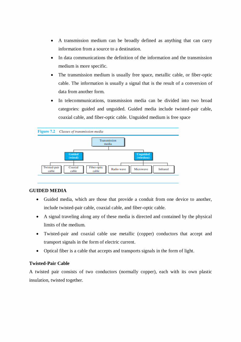
In telecommunications, transmission media can be divided into two broad
categories: guided and unguided. Guided media include twisted-pair cable,
coaxial cable, and fiber-optic cable. Unguided medium is free space
GUIDED MEDIA
Guided media, which are those that provide a conduit from one device to another,
include twisted-pair cable, coaxial cable, and fiber-optic cable.
A signal traveling along any of these media is directed and contained by the physical
limits of the medium.
Twisted-pair and coaxial cable use metallic (copper) conductors that accept and
transport signals in the form of electric current.
Optical fiber is a cable that accepts and transports signals in the form of light.
Twisted-Pair Cable
A twisted pair consists of two conductors (normally copper), each with its own plastic
insulation, twisted together.
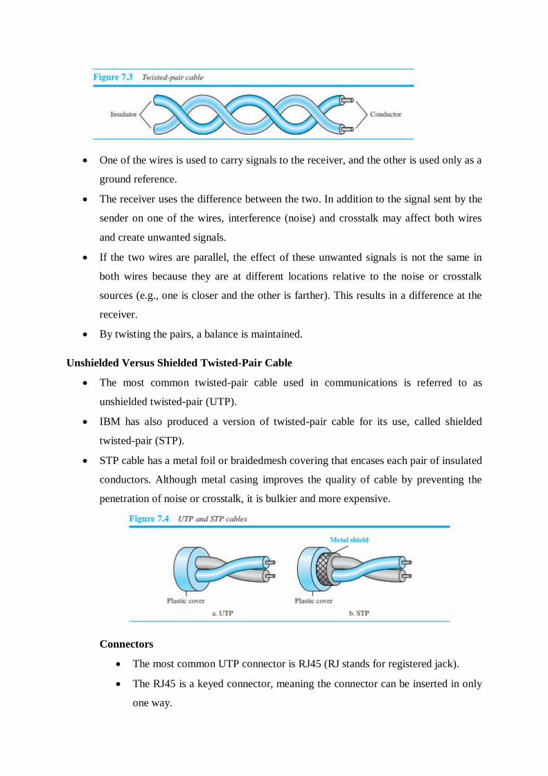
One of the wires is used to carry signals to the receiver, and the other is used only as a
ground reference.
The receiver uses the difference between the two. In addition to the signal sent by the
sender on one of the wires, interference (noise) and crosstalk may affect both wires
and create unwanted signals.
If the two wires are parallel, the effect of these unwanted signals is not the same in
both wires because they are at different locations relative to the noise or crosstalk
sources (e.g., one is closer and the other is farther). This results in a difference at the
receiver.
By twisting the pairs, a balance is maintained.
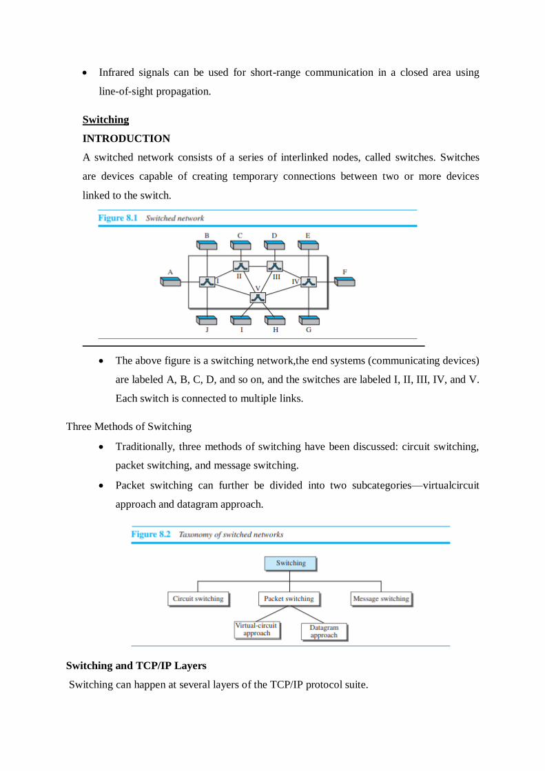
Unshielded Versus Shielded Twisted-Pair Cable
The most common twisted-pair cable used in communications is referred to as
unshielded twisted-pair (UTP).
IBM has also produced a version of twisted-pair cable for its use, called shielded
twisted-pair (STP).
STP cable has a metal foil or braidedmesh covering that encases each pair of insulated
conductors. Although metal casing improves the quality of cable by preventing the
penetration of noise or crosstalk, it is bulkier and more expensive.
Connectors
The most common UTP connector is RJ45 (RJ stands for registered jack).
The RJ45 is a keyed connector, meaning the connector can be inserted in only
one way.

One way to measure the performance of twisted-pair cable is to compare
attenuation versus frequency and distance.
A twisted-pair cable can pass a wide range of frequencies.
Applications: Twisted-pair cables are used in telephone lines to provide voice
and data channels.
Coaxial Cable
Coaxial cable (or coax) carries signals of higher frequency ranges than those
in twistedpair cable, in part because the two media are constructed quite
differently.
Instead of having two wires, coax has a central core conductor of solid or
stranded wire (usually copper) enclosed in an insulating sheath, which is, in
turn, encased in an outer conductor of metal foil, braid, or a combination of
the two.
The outer metallic wrapping serves both as a shield against noise and as the
second conductor, which completes the circuit. This outer conductor is also
enclosed in an insulating sheath, and the whole cable is protected by a plastic
cover

To connect coaxial cable to devices, we need coaxial connectors. The
most common type of connector used today is the Bayonet Neill-
Concelman (BNC) connector.
The attenuation is much higher in coaxial cable than in twisted-pair
cable. In other words, although coaxial cable has a much higher
bandwidth, the signal weakens rapidly and requires the frequent use of
repeaters.
Traditional Ethernet LANs, digital telephone networks, Cable TV
networks also use coaxial cables.
Fiber-Optic Cable
A fiber-optic cable is made of glass or plastic and transmits signals in the form of
light.
Optical fibers use reflection to guide light through a channel. A glass or plastic core is
surrounded by a cladding of less dense glass or plastic.
The difference in density of the two materials must be such that a beam of light
moving through the core is reflected off the cladding instead of being refracted into it.
Propagation Modes
Current technology supports two modes (multimode and single mode) for propagating
light along optical channels, each requiring fiber with different physical
characteristics.
Multimode can be implemented in two forms: step-index or graded-index.

Multimode
Multimode is so named because multiple beams from a light source move
through the core in different paths. How these beams move within the cable
depends on the structure of the core.
In multimode step-index fiber, the density of the core remains constant from
the center to the edges. A beam of light moves through this constant density in
a straight line until it reaches the interface of the core and the cladding
A second type of fiber, called multimode graded-index fiber, decreases this
distortion of the signal through the cable. The word index here refers to the
index of refraction.

Single-mode uses step-index fiber and a highly focused source of light that
limits beams to a small range of angles, all close to the horizontal.
Fiber-Optic Cable Connectors
There are three types of connectors for fiber-optic cables
The subscriber channel (SC) connector is used for cable TV. It uses a
push/pull locking system.
The straight-tip (ST) connector is used for connecting cable to
networking devices. It uses a bayonet locking system and is more
reliable than SC.
MT-RJ is a connector that is the same size as RJ45.
Fiber-optic cable is often found in backbone networks because its wide
bandwidth is cost-effective.
Fiber-optic cable is often found in backbone networks because its wide
bandwidth is cost-effective.
Advantages and Disadvantages of Optical Fiber
Advantages
Fiber-optic cable has several advantages over metallic cable (twisted-pair or coaxial).
❑ Higher bandwidth.
Fiber-optic cable can support dramatically higher bandwidths (and hence data rates) than
either twisted-pair or coaxial cable. Currently, data rates and bandwidth utilization over fiber-
optic cable are limited not by the medium but by the signal generation and reception
technology available.
❑ Less signal attenuation.
Fiber-optic transmission distance is significantly greater than that of other guided media. A
signal can run for 50 km without requiring regeneration. We need repeaters every 5 km for
coaxial or twisted-pair cable.
❑ Immunity to electromagnetic interference.
Electromagnetic noise cannot affect fiber-optic cables.
❑ Resistance to corrosive materials.
Glass is more resistant to corrosive materials than copper.
❑ Light weight.

Fiber-optic cables are much lighter than copper cables.
❑ Greater immunity to tapping.
Fiber-optic cables are more immune to tapping than copper cables. Copper cables create
antenna effects that can easily be tapped.
Disadvantages
There are some disadvantages in the use of optical fiber.
❑ Installation and maintenance.
Fiber-optic cable is a relatively new technology. Its installation and maintenance require
expertise that is not yet available everywhere.
❑ Unidirectional light propagation.
Propagation of light is unidirectional. If we need bidirectional communication, two fibers are
needed.
❑ Cost.
The cable and the interfaces are relatively more expensive than those of other guided media.
If the demand for bandwidth is not high, often the use of optical fiber cannot be justified.
UNGUIDED MEDIA: WIRELESS
Unguided medium transport electromagnetic waves without using a physical
conductor.
This type of communication is often referred to as wireless communication. Signals
are normally broadcast through free space and thus are available to anyone who has a
device capable of receiving them.

In ground propagation, radio waves travel through the lowest portion of the
atmosphere, hugging the earth.
. In sky propagation, higher-frequency radio waves radiate upward into the ionosphere
(the layer of atmosphere where particles exist as ions) where they are reflected back to
earth. This type of transmission allows for greater distances with lower output power.
In line-of-sight propagation, very high-frequency signals are transmitted in straight
lines directly from antenna to antenna.

We can divide wireless transmission into three broad groups: radio waves,
microwaves, and infrared waves.
Radio Waves
Electromagnetic waves ranging in frequencies between 3 kHz and 1 GHz are
normally called radio waves; waves ranging in frequencies between 1 and 300 GHz
are called microwaves.
Radio waves, for the most part, are omni directional. When an antenna transmits radio
waves, they are propagated in all directions. This means that the sending and
receiving antennas do not have to be aligned.
A sending antenna sends waves that can be received by any receiving antenna.
The omni directional property has a disadvantage, too. The radio waves transmitted
by one antenna are susceptible to interference by another antenna that may send
signals using the same frequency or band.
Radio waves, particularly those waves that propagate in the sky mode, can travel long
distances.
Applications
The omni directional characteristics of radio waves make them useful for
multicasting, in which there is one sender but many receivers. AM and FM radio,
television, maritime radio, cordless phones, and paging are examples of multicasting.
Microwaves
Electromagnetic waves having frequencies between 1 and 300 GHz are called
microwaves.
Microwaves are unidirectional. When an antenna transmits microwaves, they can be
narrowly focused. This means that the sending and receiving antennas need to be
aligned.
The unidirectional property has an obvious advantage.
characteristics of microwave propagation:
❑ Microwave propagation is line-of-sight.
Since the towers with the mounted antennas need to be in direct sight of each other,
towers that are far apart need to be very tall. Repeaters are often needed for
longdistance communication

❑ Very high-frequency microwaves cannot penetrate walls. This characteristic can be
a disadvantage if receivers are inside buildings.
❑ The microwave band is relatively wide, almost 299 GHz. Therefore wider
subbands can be assigned, and a high data rate is possible.
❑ Use of certain portions of the band requires permission from authorities.
Unidirectional Antenna Microwaves need unidirectional antennas that send
out signals in one direction
Two types of antennas are used for microwave communications: the parabolic
dish and the horn
Applications Microwaves, due to their unidirectional properties, are
very useful when unicast (oneto-one) communication is needed
between the sender and the receiver.
They are used in cellular phones satellite networks and wireless
LANs.
Infrared
Infrared waves, with frequencies from 300 GHz to 400 THz (wavelengths from 1 mm
to 770 nm), can be used for short-range communication.
Infrared waves, having high frequencies, cannot penetrate walls. This advantageous
characteristic prevents interference between one system and another;
we cannot use infrared waves outside a building because the sun’s rays contain
infrared waves that can interfere with the communication.
Infrared signals can be used for short-range communication in a closed area using
line-of-sight propagation.
Switching
INTRODUCTION
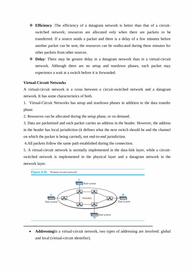
A switched network consists of a series of interlinked nodes, called switches. Switches
are devices capable of creating temporary connections between two or more devices
linked to the switch.
The above figure is a switching network,the end systems (communicating devices)
are labeled A, B, C, D, and so on, and the switches are labeled I, II, III, IV, and V.
Each switch is connected to multiple links.
Three Methods of Switching
Traditionally, three methods of switching have been discussed: circuit switching,
packet switching, and message switching.
Packet switching can further be divided into two subcategories—virtualcircuit
approach and datagram approach.
Switching and TCP/IP Layers
Switching can happen at several layers of the TCP/IP protocol suite.

Switching at Physical Layer
At the physical layer, we can have only circuit switching. There are no packets
exchanged at the physical layer. The switches at the physical layer allow signals to
travel in one path or another.
Switching at Data-Link Layer
At the data-link layer, we can have packet switching. However, the term packet in
this case means frames or cells. Packet switching at the data-link layer is normally
done using a virtual-circuit approach.
Switching at Network Layer
At the network layer, we can have packet switching. In this case, either a virtual-
circuit approach or a datagram approach can be used. Currently the Internet uses a
datagram approach.
Switching at Application Layer
At the application layer, we can have
only message switching. The communication at the application layer occurs by
exchanging messages.
CIRCUIT-SWITCHED NETWORKS
A circuit-switched network is made of a set of switches connected by physical links, in which
each link is divided into n channels.
❑ Circuit switching takes place at the physical layer.
In circuit switching, the resources need to be reserved during the setup phase; the
resources remain dedicated for the entire duration of data transfer until the teardown
phase.
❑ Before starting communication, the stations must make a reservation for the resources to
be used during the communication. These resources, such as channels, switch buffers, switch
processing time, and switch input/output ports, must remain dedicated during the entire
duration of data transfer until the teardown phase.
❑ Data transferred between the two stations are not packetized. The data are a continuous
flow sent by the source station and received by the destination station, although there may be
periods of silence

❑ There is no addressing involved during data transfer. The switches route the data based on
their occupied band (FDM) or time slot (TDM).
Three Phases
The actual communication in a circuit-switched network requires three phases:
connection setup, data transfer, and connection teardown.
Setup Phase
Before the two parties can communicate, a dedicated circuit needs to be established.
The end systems are normally connected through dedicated lines to the switches. so
connection setup means creating dedicated channels between the switches.
Data-Transfer Phase
After the establishment of the dedicated circuit (channels), the two parties can transfer
data.
Teardown Phase
When one of the parties needs to disconnect, a signal is sent to each switch to release
the resources.
Efficiency: Circuit-switched networks are not as efficient as the other two types of
networks because resources are allocated during the entire duration of the connection.
These resources are unavailable to other connections.
Delay :Although a circuit-switched network normally has low efficiency, the delay in
this type of network is minimal. During data transfer the data are not delayed at each
switch; the resources are allocated for the entire duration of the connection.
PACKET SWITCHING
In data communications, we need to send messages from one end system to another. If
the message is going to pass through a packet-switched network, it needs to be

divided into packets of fixed or variable size. The size of the packet is determined by
the network and the governing protocol.
In a packet-switched network, there is no resource reservation; resources are allocated
on demand.
We can have two types of packet-switched networks: datagram networks and
virtualcircuit networks.
Datagram Networks
In a datagram network, each packet is treated independently of all others. Even
if a packet is part of a multipacket transmission, the network treats it as though
it existed alone. Packets in this approach are referred to as datagrams.
Datagram switching is normally done at the network layer.
The datagram networks are sometimes referred to as connectionless networks.
The term connectionless here means that the switch (packet switch) does not
keep information about the connection state. There are no setup or teardown
phases. Each packet is treated the same by a switch regardless of its source or
destination.
A switch in a datagram network uses a routing table that is based on the destination
address.
The routing tables are dynamic and are updated periodically. The destination
addresses and the corresponding forwarding output ports are recorded in the tables.
Every packet in a datagram network carries a header that contains, among other
information, the destination address of the packet.
The destination address in the header of a packet in a datagram network remains the
same during the entire journey of the packet.
Efficiency :The efficiency of a datagram network is better than that of a circuit-
switched network; resources are allocated only when there are packets to be
transferred. If a source sends a packet and there is a delay of a few minutes before
another packet can be sent, the resources can be reallocated during these minutes for
other packets from other sources.
Delay: There may be greater delay in a datagram network than in a virtual-circuit
network. Although there are no setup and teardown phases, each packet may
experience a wait at a switch before it is forwarded.
Virtual-Circuit Networks
A virtual-circuit network is a cross between a circuit-switched network and a datagram
network. It has some characteristics of both.
1. Virtual-Circuit Networks has setup and teardown phases in addition to the data transfer
phase.
2. Resources can be allocated during the setup phase, or on demand.
3. Data are packetized and each packet carries an address in the header. However, the address
in the header has local jurisdiction (it defines what the next switch should be and the channel
on which the packet is being carried), not end-to-end jurisdiction.
4.All packets follow the same path established during the connection.
5. A virtual-circuit network is normally implemented in the data-link layer, while a circuit-
switched network is implemented in the physical layer and a datagram network in the
network layer.
AddressingIn a virtual-circuit network, two types of addressing are involved: global
and local (virtual-circuit identifier).

o Global Addressing A source or a destination needs to have a global address—
an address that can be unique in the scope of the network.
o Virtual-Circuit Identifier The identifier that is actually used for data transfer
is called the virtual-circuit identifier (VCI) or the label. A VCI, unlike a global
address, is a small number that has only switch scope; it is used by a frame
between two switches. When a frame arrives at a switch, it has a VCI; when it
leaves, it has a different VCI.
Three Phases
o The three phases in a virtual-circuit network: setup, data transfer, and
teardown.
o Data-Transfer Phase
To transfer a frame from a source to its destination, all switches need
to have a table entry for this virtual circuit. The table, in its simplest
form, has four columns.
The data-transfer phase is active until the source sends all its frames to
the destination. The procedure at the switch is the same for each frame
of a message. The process creates a virtual circuit, not a real circuit,
between the source and destination.
o Setup Phase
In the setup phase, a switch creates an entry for a virtual circuit. For
example, suppose source A needs to create a virtual circuit to B. Two
steps are required: the setup request and the acknowledgment.
Initially A setup request frame is sent from the source to the
destination. After the entries in the switching tables gets completed A
special frame, called the acknowledgment frame id generated
o Teardown Phase
In this phase, source A, after sending all frames to B, sends a special
frame called a teardown request. Destination B responds with a
teardown confirmation frame. All switches delete the corresponding
entry from their tables.
In virtual-circuit switching, all packets belonging to the same source and destination
travel the same path, but the packets may arrive at the destination with different
delays if resource allocation is on demand.

Switching at the data-link layer in a switched WAN is normally implemented by
using virtual-circuit techniques.