Embed Size (px)
Citation preview

Prepared By: Prof.Y.M. Halde (Department of Mechanical Engineering) Page1 of 28
Subject
Mechanical working drawing
( 22341)

Prepared By: Prof.Y.M. Halde (Department of Mechanical Engineering) Page2 of 28
Chapter No. Name of chapter Marks With
Option
1 Development of surfaces 18
2 Intersection of solids 21
3 Conventional representation 08
4 Production drawing 14
5 Details to assembly 32
6 Assembly to details 32
Total Marks :- 125

Prepared By: Prof.Y.M. Halde (Department of Mechanical Engineering) Page3 of 28
Q.1 Attempt any FIVE 5*2=10
a) Conventional representation
b) Conventional representation
c) Conventional representation
d) Conventional representation
e) Production drawing
f) Production drawing
g) Production drawing
Q.2 Attempt any ONE 2*7=14
a) Intersection of solids
b) Intersection of solids
c) Intersection of solids
Q.3 A Attempt any ONE 1*4=08
a) Production drawing
b) Production drawing
Q.3 B Attempt any TWO 2*6=12
a) Development of surfaces
b) Development of surfaces
c) Development of surfaces
Q.4 Attempt any following compulsory (Assembly to details) 1*16=16
Q.5 Attempt any one 1*16=16
a) Details to assembly
b) Details to assembly

Prepared By: Prof.Y.M. Halde (Department of Mechanical Engineering) Page4 of 28
Syllabus:-
Unit
No. Name of the Unit
Course Outcome
(CO)
1 Development of surfaces CO-341.01
2 Intersection of solids CO-341.02
3 Conventional representation CO-341.03
Q.1
Attempt any THREE 3*2=6Marks
Course Outcome
(CO)
a) Conventional representation CO-341.03
b) Conventional representation CO-341.03
c) Conventional representation CO-341.03
d) Conventional representation CO-341.03
Q.2 Attempt any ONE 1*7=7 Marks
a) Development of surfaces CO-341.01
b) Development of surfaces CO-341.01
Q.2 Attempt any ONE 1*7= 7Marks
a) Intersection of solids CO-341.02
b) Intersection of solids CO-341.02

Prepared By: Prof.Y.M. Halde (Department of Mechanical Engineering) Page5 of 28
Syllabus:-
Unit
No.
Name of the Unit
Course Outcome
(CO)
3 Production drawing CO-341.04
4 Details to assembly CO-341.05
5 Assembly to details CO-341.06
Q.1
Attempt any ONE 1*4= 4Marks
Course
Outcome
(CO)
a) Production drawing CO-341.04
b) Production drawing CO-341.04
Q.2 Attempt any ONE 1*7=8Marks
a) Details to assembly CO-341.05
b) Details to assembly CO-341.05
Q.2 Attempt any ONE 1*7= 8Marks
a) Assembly to details CO-341.06
b) Assembly to details CO-341.06
Prepared By: Prof.Y.M. Halde (Department of Mechanical Engineering) Page6 of 28
COURSE:- Mechanical Working Drawing (22341)
PROGRAMME: - ALL
CO.NO Course Outcome
CO-103.1 Draw Development of lateral surface of various solids
CO-103.2 Draw intersection of curves of different solids
CO-103.3 Use various drawing codes, convention & their symbol
CO-103.4 Use Production drawing , used for produce for products
CO-103.5 Draw assembly of product
CO-103.6 Draw Details of product

Prepared By: Prof.Y.M. Halde (Department of Mechanical Engineering) Page7 of 28
UNIT-1 . Development of surfaces (Total Marks =08)
1. A vertical cylinder of 70 mm diameter is penetrated by another cylinder of 50 mm
diameter. The axis of the penetrating cylinder is parallel to both H.P. and V.P. and is 8 mm
away from the axis of the vertical cylinder. Draw its projections showing curves of
intersection.
2. A vertical cylinder of diameter of 70 mm and height 100 mm is completely penetrated by
a horizontal square prism of side 50 mm and length 110 mm. The axis of the prism bisects
the axis of the cylinder. All the rectangular faces of the prism are equally inclined to H.P.
Draw Front View, Top View and
Side View showing the curves of intersection.
3. A cone with base diameter 80 mm and axis height 75 mm is kept on the H.P. on its base.
It is penetrated by a horizontal cylinder of diameter 40 mm with its axis parallel to V.P. and
intersecting the axis of the cone at a distance of 25 mm above the base of the cone. Draw
the projections solid showing curves of intersection.
4. Draw the development of the lateral surface of the cylinder having a
square hole in it as shown in the Fig.
5. Draw the development of lateral surface of Part ‘A’ and Part ‘B’ of a
right angle elbow shown in Fig

Prepared By: Prof.Y.M. Halde (Department of Mechanical Engineering) Page8 of 28
6. A square prism of base side 40 mm and height 80 mm rests on HP with all faces equally
inclined to VP. It is cut by a plane perpendicular to VP and 60° inclined to HP passing
through a point on axis 55 mm from base. Draw development of lateral surface of the prism.
7. A cone of base diameter 60 mm and 70 mm long axis rests on HP on its base. It is cut by
a section plane perpendicular to VP and inclined 45° to HP passing from a point on axis 35
mm from apex. Draw development of lateral surface of cone.
8. Develop lateral surface of 90° elbow. Each pipe diameter is 60 mm. Maximum length of
each leg is 80 mm.
9. A cone resting on H.P is having diameter of base. 45 mm and height 60 mm. If is cut by a
vertical plane perpendicular to V.P and 10 mm away from the axis of cone. Draw the
development of lateral surface of the cone.
10. Fig. shows a right circular cylinder of diameter60 mm and height of axis 100 mm it is
cut as shown. Draw the development of its lateral surface.
Prepared By: Prof.Y.M. Halde (Department of Mechanical Engineering) Page9 of 28
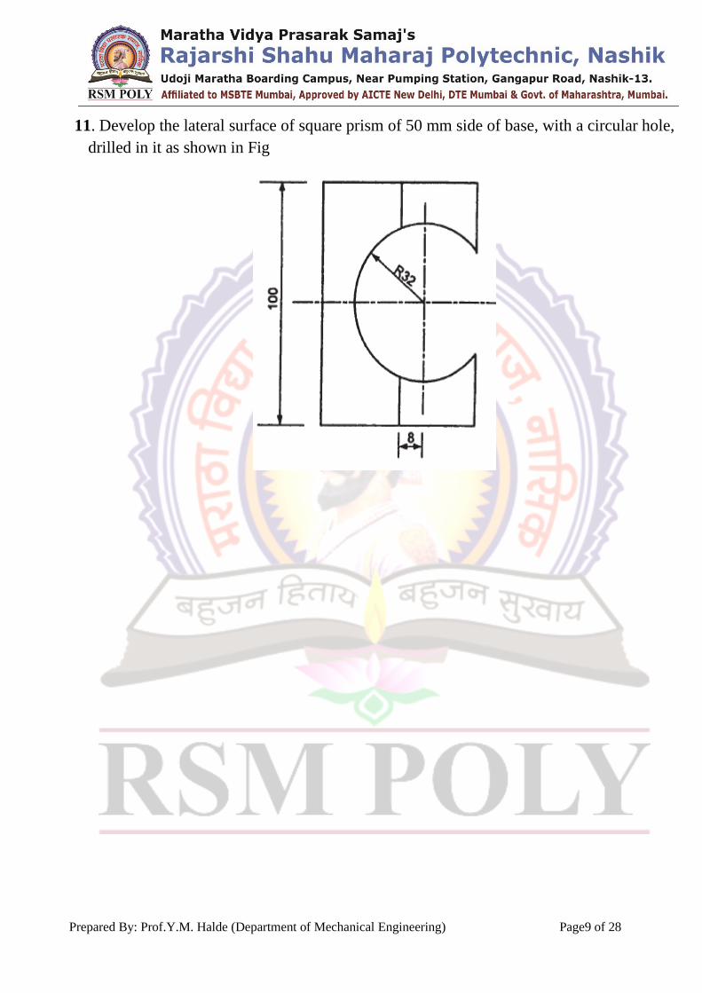
11. Develop the lateral surface of square prism of 50 mm side of base, with a circular hole,
drilled in it as shown in Fig

Prepared By: Prof.Y.M. Halde (Department of Mechanical Engineering) Page10 of 28
UNIT- 2. Intersection of solids (Total Marks =14)
1. A vertical cylinder 85 mm diameter is penetrated by another cylinder of 60 mm
diameter, the axis of which is parallel to both H.P. and V.P. The two axes are 8 mm apart.
Draw the projections showing curves of intersection.
2. A vertical square prism base 50 mm side has its faces equally inclined to V.P. It is
completely penetrated by another square prism of base 30 mm side, the axis of which is
parallel to both H.P. and V.P. and is 6 mm away from the axis of the vertical prism. The
faces of horizontal prism are also equally inclined to the V.P. Draw the projections of solids
showing the lines of intersection.
3. A square hole of 35 mm side is cut in a cylindrical shaft 75 mm diameter and 125 mm
long. The axis of the hole intersects that of the shaft at right angles. All faces of the hole are
inclined at 45degree to the H.P. Draw the three views of the shaft when the plane of the
two axes is parallel to the V.P.
4. A vertical cylinder of 70 mm diameter is penetrated by another cylinder of 50mm
diameter. The axis of the penetrating cylinder is parallel to both H.P. and V.P. and is 8 mm
away from the axis of the vertical cylinder. Draw its projections showing curves of
intersection.
5. A vertical cylinder of diameter of 70 mm and height 100 mm is completely penetrated
by a horizontal square prism of side 50 mm and length 110 mm. The axis of the prism
bisects the axis of the cylinder. All the rectangular faces of the prism are equally inclined to
H.P. Draw Front View, Top View and Side View showing the curves of intersection.
6. A cone with base diameter 80 mm and axis height 75 mm is kept on the H.P. on its base.
It is penetrated by a horizontal cylinder of diameter 40 mm with its axis parallel to V.P. and
intersecting the axis of the cone at a distance of 25 mm above the base of the cone. Draw
the projections solid showing curves of intersection

Prepared By: Prof.Y.M. Halde (Department of Mechanical Engineering) Page11 of 28
7. A cone with base diameter 80 mm and axis height 75 mm is kept on the H.P. on it’s base.
It is penetrated by a horizontal cylinder of diameter 40 mm with it’s axis parallel to V.P.
and intersecting the axis of the cone at a distance of 25 mm above the base of the cone.
Draw the projections of solid showing curves of intersection.
8. A vertical square prism side of base 35 mm and 80 mm long has it’s vertical faces
equally inclined to V.P. It is penetrated by another square prism side of base 35 mm and
axis length 80 mm so flat it’s axis parallel to both H.P. and V.P. and is 10 mm in front of
the axis of the vertical prism. The faces of the penetrating prism are equally inclined to H.P.
Draw the projections of the prisms showing lines of intersection.
9. A vertical square prism 50 mm side of base and 100 mm long having it’s faces equally
inclined to the V.P. is completely penetrated by a horizontal cylinder 40 mm diameter and
100 mm long the axis of which is parallel to V.P. and 6 mm away from that of axis of
prism. Draw the projections of the solids showing curves of intersection
10. A cone with base diameter 70 mm & axis height 65 mm is kept on HP on its
base. It is penetrated by a horizontal cylinder of diameter 35 mm with its axis
parallel to VP & intersecting axis of cone at distance of 20 mm above base of
cone. Draw projection of solid showing curve of intersection.

Prepared By: Prof.Y.M. Halde (Department of Mechanical Engineering) Page12 of 28
UNIT- 3. Conventional Representation (Total Marks =06)
1. Draw the conventional representation of the following :
(i) Cylindrical helical compression spring of wire of circular cross-section
(ii) Semi-elliptic leaf spring.
2. Draw a part showing fillet radius and chamfered edge.
3. Draw the conventional representation of :
(i) Spur gear
(ii) Bevel gear.
4. Draw the actual view and conventional representation of
(i) External screw thread
(ii) Straight knurling.
5. Draw the conventional representation of the following :
(i) I-section or rolled section
(ii) Long Break in pipe
7. Draw the conventional representation for common feature.
(i) Radial Ribs
(ii) Bearings
6. Draw the actual sketch of Counter Bore and Counter Sunk hole.
7. Draw the actual sketch and conventional representation :
(i) Spiral Spring
(ii) Semi-elliptic leaf spring with eyelets.
8. Draw the conventional representation for common feature
(a) Revolved section
(b) Splined shaft
(c) Worm gear
(d) Internal thread
(e) Compression spring with square section
(f) Roller bearing
(g) Globe valve

Prepared By: Prof.Y.M. Halde (Department of Mechanical Engineering) Page13 of 28
9. Draw conventional representation for any SIX of the following : 12
(i) Steel
(ii) Diamond knurling
(iii) Helical spring with flat end
(iv) Bevel gear
(v) I-section
(vi) Ball and Roller bearing
(vii) Gate valve
(viii) Internal screw thread
10. Draw Conventional representation for any SIX of the following : 12
(a) Offset section
(b) Globe valve
(c) Diamond Knurling
(d) Leaf spring with eyes and central Band
(e) Wood
(f) Spur gears
(g) Counter bored holes
(h) Ball and Roller bearings

Prepared By: Prof.Y.M. Halde (Department of Mechanical Engineering) Page14 of 28
UNIT- 4. Production Drawing (Total Marks =10)
1. State the meaning of the symbol shown in Fig.
2. State the meaning of symbols shown in the Fig.
3. Refer Fig. and state the meaning of symbol at X.
4. Refer Fig. and state the meaning of symbol X and Y.
5. Define : (i) Allowance (ii) Clearance (iii) Interference (iv) Deviation

Prepared By: Prof.Y.M. Halde (Department of Mechanical Engineering) Page15 of 28
6. Write the symbol for light press fit, and give its two applications.
7. A bush bearing has internal diameter and the shaft diameter is
. Find the minimum and maximum clearance and identify the type of fit
between bush and shaft.
8. A bush bearing has internal diameter and the shaft diameter is 50 .
Find the minimum and maximum clearance and identify the type of fit between bush and
shaft.
9. Draw a sketch showing basic size, lower deviation, upper deviation and tolerance.
10. Draw the symbols representing the characteristics to be tolerance.
(i) Circularity
(ii) Cylindricity.
11. Draw the symbol for the following
(i) Concave fillet weld
(ii) Seam Weld
(iii) Flat Single V butt Weld
(iv) Square butt weld
12. Draw the symbol of the following :
(i) Square butt
(ii) Double J-butt
(iii) Spot weld
(iv) Convex fillet weld

Prepared By: Prof.Y.M. Halde (Department of Mechanical Engineering) Page16 of 28
13. Refer Fig. 3. What is the meaning of at ‘x’ and ‘y’
14. Two mild steel plates of 8 mm thickness are to be welded to have a lap joint by a fillet
weld of leg length 8 mm. Represent the weld on drawing with proper symbols.
15. Represent a welding drawing of A right circular cylinder is to be welded to a steel plate
at right angles to it, with all round fillet weld of 6 mm leg length.
16. Represent the welding drawing of two shafts with equal diameter welded end to end by
means of square butt weld with convex counter of site.

Prepared By: Prof.Y.M. Halde (Department of Mechanical Engineering) Page17 of 28
UNIT- 5. Details to Assembly (Total Marks =16)
1. Fig. shows details of Pedestal Bearing.
Draw : (i) Half Sectional front view of Assembly (ii) Top view of Assembly

Prepared By: Prof.Y.M. Halde (Department of Mechanical Engineering) Page18 of 28
2. Fig. shows details of Tool Post. Draw : (i) Half sectional front view of Assembly
(ii) Top view of Assembly

Prepared By: Prof.Y.M. Halde (Department of Mechanical Engineering) Page19 of 28
3. Fig. shows the details of screw jack. Draw the (i) Sectional Front View
(ii) Top view
(iii) Part List and Dimensions

Prepared By: Prof.Y.M. Halde (Department of Mechanical Engineering) Page20 of 28
4. Fig. shows the details of Oldham’s coupling. Draw the following views of the assembly
(i) Sectional Front View (ii) Left hand Side View

Prepared By: Prof.Y.M. Halde (Department of Mechanical Engineering) Page21 of 28
5. Figure No. shows the details of foot step bearing. Draw sectional F.V. and
T.V. of the Assembly prepare bill of material.

Prepared By: Prof.Y.M. Halde (Department of Mechanical Engineering) Page22 of 28
6. Fig. Shows the details of Oldham’s coupling. Draw sectional F.V. and LHSV of
assembly. Prepare bill of material.

Prepared By: Prof.Y.M. Halde (Department of Mechanical Engineering) Page23 of 28
UNIT- 6. Assembly to Details (Total Marks =16)
1. Fig. shows the assembly of Non-Return Valve, Attempt any two of the
Following (1) Draw the Sectional Front View and Top View of body.
(2) Draw the Front View and Top View of Valve.
(3) Draw the Sectional Front View and Top View of Cover.
Prepared By: Prof.Y.M. Halde (Department of Mechanical Engineering) Page24 of 28
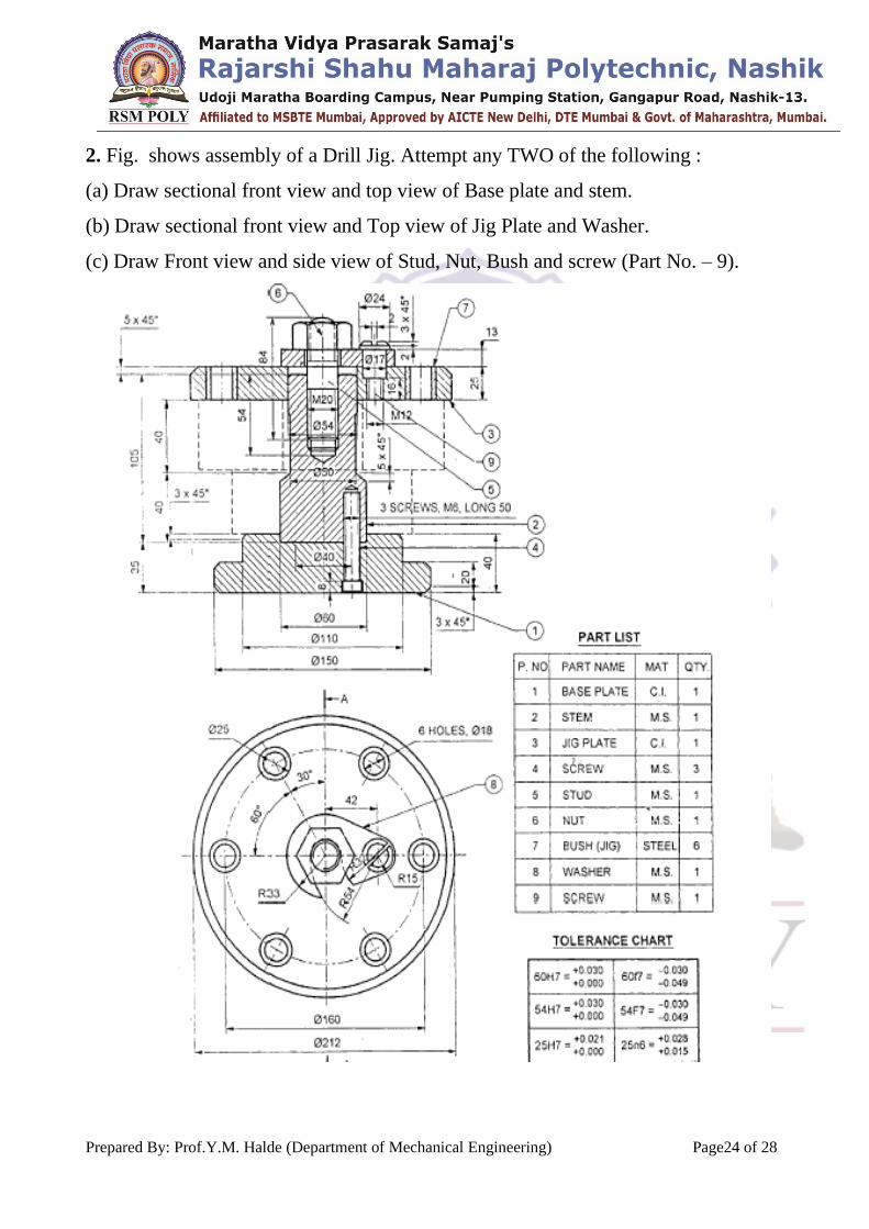
2. Fig. shows assembly of a Drill Jig. Attempt any TWO of the following :
(a) Draw sectional front view and top view of Base plate and stem.
(b) Draw sectional front view and Top view of Jig Plate and Washer.
(c) Draw Front view and side view of Stud, Nut, Bush and screw (Part No. – 9).

Prepared By: Prof.Y.M. Halde (Department of Mechanical Engineering) Page25 of 28
3. Shows Assembly of Lathe tail stock
Draw detail drawing of the following parts :
(1) Body sect F.V. & S.V.
(2) Barrel sect F.V. & S.V.
(3) Spindle Bearing sect F.V. & S.V.

Prepared By: Prof.Y.M. Halde (Department of Mechanical Engineering) Page26 of 28
4. shows the assembly of Plummer block. Draw half sectional orthographic
views of the following :
(i) Body – F.V. & T.V.
(ii) Brass – F.V. & T.V.
(iii) Cap – F.V. & T.V.
(iv) Bolt – F.V. & T.V.
Prepared By: Prof.Y.M. Halde (Department of Mechanical Engineering) Page27 of 28
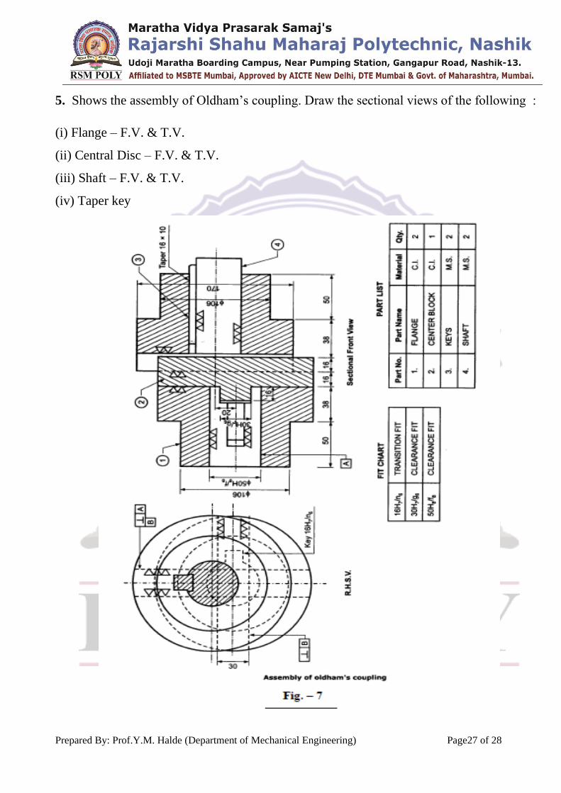
5. Shows the assembly of Oldham’s coupling. Draw the sectional views of the following :
(i) Flange – F.V. & T.V.
(ii) Central Disc – F.V. & T.V.
(iii) Shaft – F.V. & T.V.
(iv) Taper key

Prepared By: Prof.Y.M. Halde (Department of Mechanical Engineering) Page28 of 28
6. Fig. shows assembly of drill jig. Draw details :
(i) Body (two views)
(ii) Component (two views)
(iii) Plate
(iv) Also show type of fit used