Embed Size (px)
Citation preview
Submission
doc.: IEEE 11-12/0421March 2012
Alina Liru Lu, NICTSlide 1
Outdoor Channel Models for 802.11afDate: 2012-03-14
Name Affiliations Address Phone email Lu Liru (Alina) NICT Smart Wireless Lab, NICT +65 6771 1006 [email protected]
Masayuki Oodo NICT Smart Wireless Lab, NICT [email protected]
Lan Zhou NICT Smart Wireless Lab, NICT [email protected]
Chen Sun NICT Smart Wireless Lab, NICT [email protected]
Yohannes Alemseged
NICT Smart Wireless Lab, NICT [email protected]
Ming Tuo Zhou NICT Smart Wireless Lab, NICT [email protected]
Hiroshi Harada NICT Smart Wireless Lab, NICT [email protected]
Authors:
Submission
doc.: IEEE 11-12/0421
Abstract In this presentation, we discuss the
channel models of VHF/UHF band for the range of about 0.1 to 15km for urban/sub-urban area to assist corresponding system design and be used for performance evaluation.
Alina Liru Lu, NICTSlide 2

Submission
doc.: IEEE 11-12/0421
Proposed Channel Models
The following three aspects will be covered in this presentationRMS Delay SpreadPath Loss ModelChannel Impulse Response Profile
to assist the PHY/MAC design, link budget calculation, system level simulation and data link simulation
Alina Liru Lu, NICTSlide 3

Submission
doc.: IEEE 11-12/0421
RMS Delay Spread
Table 1 shows the calculated RMS Delay Spread based on VHF band measurement results for Japan Public broadband network [1].The average RMS delay spread highly depends on the environment such as terrain type.
Table 1
Table 2 [2]
[1] M. OODO, N. SOMA, R. FUNADA and H. HARADA, “Channel Model for Broadband Wireless Communication in the VHF-band”, IEICE Technical Report
Index of Measured Points
P16 P5 P4 P1 P3 P6 P15 P2 P7 P14 P8 P13 P12 P11 P10 P9
Distance (km) 1.4 1.5 1.6 1.8 1.8 2.7 2.8 3.2 4.7 6.1 7.7 9.6 12.3 13.6 15.6 16
RMS Delay Spread (µs)
0.61 029 0.45 0.4 1.4 0.82 0.29 7.9 0.74 1.79 20.6 12.2 10.9 8.4 6.5 17.8
Measure frequency 200MHz
Hb=45m
Hm=2m
BS Power 20W
Alina Liru Lu, NICTSlide 4

Submission
doc.: IEEE 11-12/0421
RMS Delay SpreadMonth Year
Slide 5
0 2 4 6 8 10 12 14 160
5
10
15
20
25
Distance (km)
RM
S D
ela
y S
prea
d (M
icro
-Se
c)
P13
P8
P12
P11
P10
P9
P14
P2
P7
P5
P4
P1P16P6
P15
P3
Worse case RMS delay can have a major impact on system performance. RMS delay spread highly depends on the environment instead of distance
Alina Liru Lu, NICT
Avg RMS delay 1.52µs
Avg RMS delay 1.52µs
Avg RMS delay 8.83µs
Avg RMS delay 8.83µs
Avg RMS delay 10.9µs
Avg RMS delay 10.9µs

Submission
doc.: IEEE 11-12/0421Month Year
Alina Liru Lu, NICTSlide 6
RMS Delay Spread
[2] Theodore S. Rappaport, Wireless Communications: Principles and Practice (2nd Edition), Prentice Hall, ISBN: 0130422320 Publish Date: Dec 31, 2007
[2]
Worse case RMS delay can have a major impact on system performance, it has better to consider worse case scenario during system design.
Submission
doc.: IEEE 11-12/0421
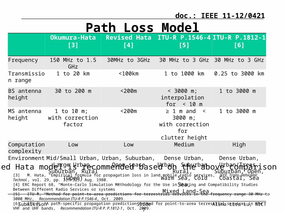
Okumura-Hata [3]
Revised Hata [4]
ITU-R P.1546-4 [5]
ITU-R P.1812-1 [6]
Frequency 150 MHz to 1.5 GHz 30MHz to 3GHz 30 MHz to 3 GHz 30 MHz to 3 GHz
Transmission range
1 to 20 km <100km 1 to 1000 km 0.25 to 3000 km
BS antenna height
30 to 200 m <200m < 3000 m; interpolation for <
10 m
1 to 3000 m
MS antenna height
1 to 10 m; with correction
factor
<200m ≥ 1 m and < 3000 m;
with correction for clutter height
1 to 3000 m
Computation complexity
Low Low Medium High
Environment Mid/Small Urban, Large Urban,
Suburban, Rural (Open)
Urban, Suburban, Open space
Dense Urban, Urban, Suburban,
Rural, Warm Sea, Cold
Sea, Mixed Land-Sea
Dense Urban, Urban/Trees,
Suburban, Open, Coastal, Sea
Path Loss Model
[3] M. Hata, “Empirical formula for propagation loss in land mobile radio services,” IEEE Trans. Vehicular Technol., vol. 29, pp. 317–325, Aug. 1980.[4] ERC Report 68, “Monte-Carlo Simulation Methodology for the Use in Sharing and Compatibility Studies Between Different Radio Services or systems”[5] ITU-R, “Method for point-to-area predictions for terrestrial services in the frequency range 30 MHz to 3000 MHz,” Recommendation ITU-R P.1546-4, Oct. 2009.[6] ITU-R, “A path-specific propagation prediction method for point-to-area terrestrial services in the VHF and UHF bands,” Recommendation ITU-R P. P.1812-1, Oct. 2009.
Revised Hata model is recommended based on the above comparison
Alina Liru Lu, NICTSlide 7
Submission
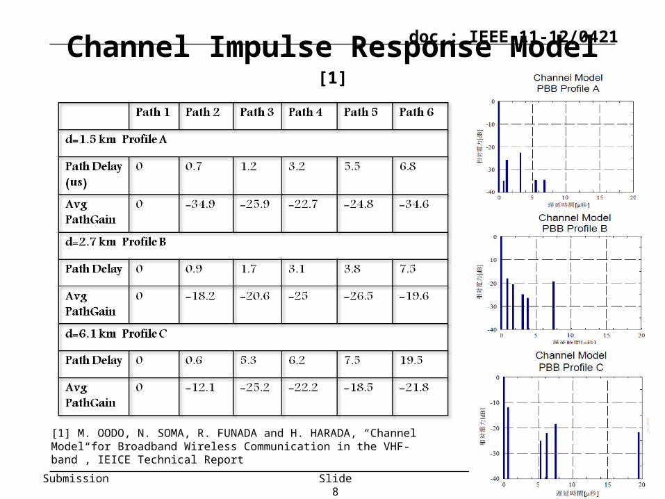
doc.: IEEE 11-12/0421Channel Impulse Response Model [1]
[1] M. OODO, N. SOMA, R. FUNADA and H. HARADA, “Channel Model for Broadband Wireless Communication in the VHF-band”, IEICE Technical Report
Alina Liru Lu, NICTSlide 8

Submission
doc.: IEEE 11-12/0421
Summary
The presentation proposes channel models for medium to long range TV White Space communications.
The proposed Channel Models covers RMS Delay SpreadPath Loss ModelChannel Impulse Response Profile
The proposed models can be considered to use for the design and simulation of TV White space communications system with communication ranges of about 0.1 to15km.
Alina Liru Lu, NICTSlide 9

Submission
doc.: IEEE 11-12/0421
References[1] M. OODO, N. SOMA, R. FUNADA and H. HARADA, “Channel Model for
Broadband Wireless Communication in the VHF-band”, IEICE Technical Report
[2] Theodore S. Rappaport, Wireless Communications: Principles and Practice (2nd Edition), Prentice Hall, ISBN: 0130422320 Publish Date: Dec 31, 2007
[3] M. Hata, “Empirical formula for propagation loss in land mobile radio services,” IEEE Trans. Veh. Technol., vol. 29, pp. 317–325, Aug. 1980.
[4] ERC Report 68, “Monte-Carlo Simulation Methodology for the Use in Sharing and Compatibility Studies Between Different Radio Services or systems”
[5] ITU-R, “Method for point-to-area predictions for terrestrial services in the frequency range 30 MHz to 3000 MHz,” Recommendation ITU-R P.1546-4, Oct. 2009.
[6] ITU-R, “A path-specific propagation prediction method for point-to-area terrestrial services in the VHF and UHF bands,” Recommendation ITU-R P. P.1812-1, Oct. 2009.
Alina Liru Lu, NICTSlide 10

Submission
doc.: IEEE 11-12/0421
Appendix
Alina Liru Lu, NICTSlide 11

Submission
doc.: IEEE 11-12/0421
Revised Hata ModelFormulas for calculation of Median Path Loss
Alina Liru Lu, NICTSlide 12

Submission
doc.: IEEE 11-12/0421
Revised Hata Model(Cont. 1)
Alina Liru Lu, NICTSlide 13

Submission
doc.: IEEE 11-12/0421
Revised Hata Model (Cont. 2)
Alina Liru Lu, NICTSlide 14

![OMF-MAC: An Opportunistic Matched Filter-based MAC in ... · viable solutions and IEEE 802.11af task group is now currently working on this topic [5]. For OSA, a MAC protocol must](https://img.pdfslide.net/doc/110x75/5e6992f08252dc0b1507f543/omf-mac-an-opportunistic-matched-filter-based-mac-in-viable-solutions-and-ieee.jpg)