Embed Size (px)
Citation preview
HITACHI GE Hitachi Nuclear EnergyRobert E. Brown
Senior Vice PresidentRegulatory Affairs
P.O. Box 780MC A-45Wilmington, NC 28402USA
T 910 675 5242F 910 362 [email protected]
MFN 07-650 Project No. 710
December 7, 2007
U.S. Nuclear Regulatory CommissionDocument Control DeskWashington, D.C. 20555-0001
Subject: NEDO-31336-A, General Electric Instrument Setpoint Methodology,September 1996
It has come to our attention that a non-proprietary (redacted) version of the acceptedproprietary GE Topical Report NEDC-31336P-A, General Electric Instrument SetpointMethodology, September 1996, was not previously provided to the NRC; therefore, theenclosed non-proprietary version is being provided to remedy this situation.
If you have any questions or require additional information regarding the informationprovided here, please contact me.
Sincerely,
Robert E. Brown
Senior Vice President, Regulatory Affairs
Thcz0's
GE Hitachi Nuclear Enerav
December 7, 2007Page 2
Enclosure:
1. NEDO-31336-A, General Electric Instrument Setpoint Methodology,September 1996
cc: MC HoncharikAE CubbageTE AbneyY DayalJC KinseyJL LeongRE MillerJA SavageeDRF
USNRC (with enclosure)USNRC (with enclosure)GEH (w/o enclosure)GEH (w/o enclosure)GEH (w/o enclosure)GEH (w/o enclosure)GEH (w/o enclosure)GEH (w/o enclosure)0000-0077-1714
GE Hitachi Nudear Enerav
Enclosure 1
MFN 07-650
NEDO-31336-A, General Electric Instrument Setpoint Methodology,September 1996
GE Nuclear Energy
NEDO-31336-AClass I
September 1996
General ElectricInstrument SetpointMethodology
W. H. Cooley, Jr.J. L. LeongM. A. SmithS. Wolf
GE Nuclear Energy
175 Curtner AvenueSan Jose, CA 95125
NEDO-31336-AClass I
September 1996
GENERAL ELECTRIC COMPANY
GENERAL ELECTRIC
INSTRUMENT SETPOINT METHODOLOGY
W. H. Cooley, Jr.
J. L. Leong
M. A. Smith
S. Wolf
Approved b3 Approved byW.KI. iarrentine
Manager
Electrical Design Engineering
R.E. Skavdahl
Services General Manager
Engineering Services
Approved by:R. Villa
Manager
Product Licensing

NEDO-31336-A
LEGAL NOTICE
This is a nonproprietary version of the document NEDC-31336P-A where theproprietary information of NEDC-31336P-A has been removed. The portionsof NEDC-31336P-A that have been removed are indicated by "bars" drawn inthe margin of the text of this report. Figures and large equation objects ofNEDC-31336P that have been removed are also identified with "bars" wherethe object was.
ii

NEDO-31336-A
TABLE OF CONTENTS
Page
ABSTRACT xiii
1. INSTRUMENT SETPOINT METHODOLOGY 1-1
1. 1 Introduction 1-1
1.2 Methodology Used to Establish 1-2
Nominal Trip Setpoints and
Technical Specification Limits
1.2.1 Definition 1-2
1.2.2 Setpoint Relationships 1-7
1.2.3 Methods Used to Establish 1-9
Nominal Trip Setpoints and
Technical Specification Limits
by Computation
1.2.4 Methods Used to Establish 1-18
Nominal Trip Setpoints and
Technical Specification Limits
by Engineering Judgement
1.2.5 Methods Used to Establish 1-21
Nominal Trip Setpoints and
Technical Specificaiton Limits
by Historical Data
1.3 Conclusion 1-22
2. INSTRUMENT ACCURACY AND DRIFT METHODOLOGY 2-1
2.1 Introduction 2-1
2.2 Methodology Used to Validate Instrument 2-1
Pccuracy and Drift Values
2.2.1 Definitions 2-1
iii
NEDO-31336-A
TABLE OF CONTENTS (Continued)
Page
2.2.2 Temperature Effect on Transmitter 2-3
Accuracy and Drift
2.2.3 Transmitter Accuracy 2-5
2.2.4 Trip Unit Accuracy 2-7
2.2.5 Transmitter Drift 2-8
2.2.6 Trip Unit Drift 2-9
2.3 Additional Devices in Instrument Channel 2-10
2.4 Static Pressure Effect on Transmitter 2-11
Accuracy (Rosemount and Gould)
2.5 Seismic Effect on Transmitter 2-12
Accuracy (Rosemount and Gould)
2.6 Radiation Effect on Transmitter 2-13
Accuracy (Rosemount and Gould)
2.7 Temperature Effect on Transmitter 2-14
Accuracy and Drift (Gould)
3. INSTRUMENT SETPOINT DESCRIPTIONS 3-1
3.1 Reactor Water Level 1 3-3
3.2 Reactor Water Level 2 3-9
3.3 Reactor Water Level 3 3-15
3.4 Reactor Water Level 8 3-21
3.5 Reactor Vessel High Pressure 3-29
3.6 Reactor Vessel High Pressure ATWS RPT 3-33
3.7 Main Steam Safety/Relief Valve-Relief and Low Low Set 3-39
3.8 Main Steam Safety/Relief Valve-Safety 3-53
3.9 ADS and Drywell Pressure Bypass Timers 3-61
3.10 Main Steam Isolation Valve Closure Position Switch 3-69
3.11 Main Steam Line Radiation ronitor 3-75
3.12 Main Steam Line Low Pressure 3-79
3.13 Main Steam Line High Flow 3-83
3.14 High Drywell Pressure 3-89
3.15 High Containment Pressure 3-93
iv
NEDO-31336-A
TABLE OF CONTENTS (.Continued)
Page
3.16 LPCI/LPCS Injection Valve Interlocks 3-99
3.17 Low Pressure ECCS Pump Discharge Pressure High 3-113
3.18 Condensate Storage Tank Low Level 3-119
3.19 Rod Block Monitor 3-125
3.20 High APRM Neutron Flux 3-133
3.21 High Simulated Thermal. Power 3-139
3.22 Low Condenser Vacuum 3-143
3.23 Turbine Control Valve Fast Closure 3-151
3.24 Turbine Stop Valve Fast Closure 3-159
3.25 Turbine First Stage Pressure 3-165
4. NRC OPEN ITEMS 4-1
4.1 NRC Item 5.1 - Environmental Effects 4-3
4.2 NRC Item 5.2 - Validation of Design Allowances 4-9
4.3 NRC Item 5.3 - The Allowable Values 4-11
4.4 NRC Item 5.4 - Expanding Manufacturers Performance 4-25
Specification
4.5 NRC Item 5.4b- APRM Validation Calculations 4-63
4.6 NRC Item 5.5 - Calibration Error Validation 4-83
4.7 NRC Item 5.6 - Statistical Methods 4-85
4.8 NRC Item 5.7 - Computer Code MIodelling Conservatisms 4-91
4.9 NRC Item 5.8 - Safety Limits 4-99
4.10 NRC Item 5.9 - Setpoints Outside GE NSSS Scope 4-103
5. REFERENCES 5-1
v/vi
NEDO-31336-A
,ILLUSTRATIONS
TitleFigre
1-1 instrument Setpoint Relationships
1-2 Methods used to Establish Nominal Trip Setpoint and
Allowable Value Limits by Engineering Judgement
3.'16-1 LPCI/LPCS Injection Valve Interlocks
(Clinton, Grand Gulf, River Bend)
3.16-2 Injection Valve Interlock (LPCI/LPCS-Perry,
LPCI-Hope Creek)
3.16-3 LPCI/LPCS Injection Valve Interlock (Nine ,ile Point 2)
3.16-4 LPCI Injection Valve (Limerick)
3.16-5 Injection Valve Interlock (LPCI/CS- Fermi 2,
CS- Hope Creek, CS- Limerick)
4.1-1 Drywell Instrument Line Arrangement
4.3-1 Typical Design Relationships
4.3,2 Idealized Worst Case
4.3-3 Realistic (Conservative) Case
4.4-1 Typical Normal and Calibration Configurations forPressure Transmitters and Trip Units
4..4-2 Model for Observed In-Service Differences (OISDs)4.4-3 Rosemount Transmitters
4.4-4 Rosemount Transmitters
4.4-5 Rosemount'Trip Units
4.4-6 Rosemount Trip Units
4.4-7 Typical Relationship Between Calibrated Span
and Upper Range Limit for a Transmitter
4.5-1 APRM - Method Used to Identify Uncertainty Factors
4.5-2 APRM Uncertainties
4.5-3 Theretical Model of Sensor Sensitivity
4.5-4 Theoretical Model for Sensor Non-Linearity4.5-5 Theoretical Model for APRM Tracking
4.5-6 Statistical Model for LPRM/APRM Signal Conditioning
Equipment
Page
1-8
1-20
3-101
3-103
3-104
3-105
3-106
4-5
4-13
4-16
4-17
4-27
4-31
4-48
4-50
4-55
4-56
4-59
4-64
4-65
4-70
4-73
4-77
4-79
vii/viii
NEDO-31336-A
Table
3.1-1
3.2-1
3.3-1
3.4-1
3.4-2
3.5-1
3.6-1
3.7-1
3.7-2
3.7-3
3.8-1
3.8-2
3.9-1
3.10-1
3.11-1
3.12-1
3.13-1
3.14-1
3.15-1
3.16-1
3.16-2
3.17-1
3.17-2
3. 18-1
3.19-1
3.20-1
3.20-2
3.21-1
3.22-1
3.23-1
3.24-1
3.25-1
TABLES
Title
Reactor Water Level 1
Reactor Water Level 2
Reactor Water Level 3
Level 8 Trip Ations Performed
Reactor Water Level 8
High Pressure Scram
Reactor Vessel High Pressure ATWS RPT
Safety/Relief Valve Information
Main Steam Safety/Relief Setpoints
SRV Low Low Set
Safety/Relief Valve Information
Main Steam Safety/Relief - Safety Setpoints
ADS and ADS Bypass Timer
MSIV Position Switch
Main Steam Line Radiation Monitor
Main Steam Low Pressure
M.ain Steam High Flow
High Drywell Pressure
High Containment Pressure
LPCI Injection Valve Interlock
CS Injection Valve Interlock
LPCS Pump ADS Interlock
LPCS Pump ADS Interlock
Condensate Storage Tank
Rod Block Monitor
Design Basis Events for High APRM Neutron
Fl ux Setpoint
High APRP4 Neutron Flux
High Simulated Thermal Power
Condenser Vacuum
Turbine Control Valve Fast Closure
Turbine Stop Valve Fast Closure
Turbine First-State Pressure
Page
3-6
3-11
3-17
3-22
3-24
3-31
3-35
3-40
3-44
3-45
3-54
3-57
3-65
3-72
3-77
3-81
3-85
3-91
3-95
3-110
3-111
3-116
3-117
3-121
3-131
3-135
3-137
3-142
3-148
3-156
3-163
3-170
ix
NEDO-31336-A
TABLES (Continued)
Table Title Page
4.3-1 Probabilities for the Idealized Worst Case 4-19
4.3-2 Probabilities for the Realistic (Conservative) Case 4-20
4.3-3 Potential Cases for Figure 4.3-3 4-21
4.3-4 Probabilities for Figure 4.3-2 4-22
4.3-5 Probabilities for Figure 4.3-3 4-23
4.5-1 APRM- Individual Uncertainties 4-66
4.5-2 APR1-- Individual Uncertainties 4-66
4.8-1 Comparision of ODYN Peak Pressure Predictions 4-92
with Test Data
4.8-2 REDY Model Conservatism for Recirculation Flow 4-95
Increase Even
4.8-3 Model Conservatism for Losss of FW Heating Event 4-97
x

NEDO-31336-A
CONTRIBUTORS
E.14. CHUM.E. DRISCOLL
E.C. ECKERTD.L. FOREMAN
R.R. GHOSHJ.M. GRAU
W.K. GREEND.A. HAMONV. HANDA
R. tJRALIDHARANR.T. REICH
N.C. SHIRLEYR.A. SIEI4ERJ.M. USHERS.A. WILSON
C.H. YEN
xi/xi i

"I
NEDO-31336-A
ABSTRACT
This report documents an improved methodology developed by the GeneralElectric Coimoan. for calculating trip setpoints in instrument systems.
The methodology presented includes a generic approach for determining
setpoints on the basis of instrument characteristics, bases for con-
firming these characteristics for selected types of instrument system
components, and suomnaries of the application of the generic approach to
selected Boiling Water Reactor protection system setpoints.
This document also includes responses to NRC Staff questions contained
in the NRC letter from T. M. Novak to John F. Carolcn, "Transmittal of
NRC Staff Report on Setpoint Methodology for General Electric Supplied
Protection System Instrumentation" (May 15, 1984).
xiii/xiv
NEDO-31336-A
1.0 INSTRUMENT SETPOINT METHODOLOGY
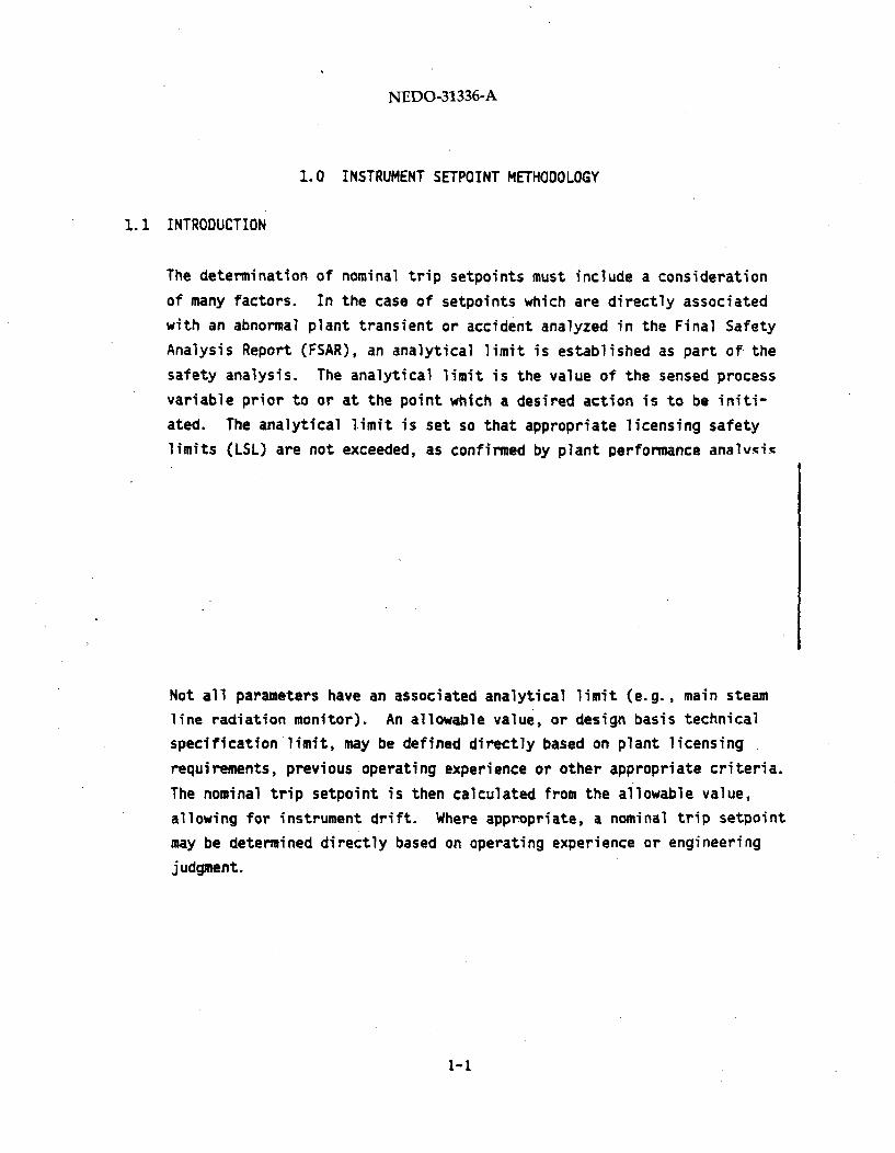
1.1 INTRODUCTION
The determination of nominal trip setpoints must include a consideration
of many factors. In the case of setpoints which are directly associated
with an abnormal plant transient or accident analyzed in the Final Safety
Analysis Report (FSAR), an analytical limit is established as part of the
safety analysis. The analytical limit is the value of the sensed processvariable prior to or at the point which a desired action is to be initi-
ated. The analytical limit is set so that appropriate licensing safety
limits (LSL) are not exceeded, as confirmed by plant performance analvnin
Not all parameters have an associated analytical limit (e.g., main steam
line radiation monitor). An allowable value, or design basis technical
specification limit, may be defined directly based on plant licensing
requirements, previous operating experience or other appropriate criteria.
The nominal trip setpoint is then calculated from the allowable value,
allowing for instrument drift. Where appropriate, a nominal trip setpoint
may be determined directly based on operating experience or engineering
judgment.
1-1
NEDO-31336-A
1.2 METHODOLOGY USED TO ESTABLISH NOMINAL TRIP SETPOINTS AND TECHNICAL
SPECIFICATION LIMITS
The following discussion relates to the methodology used for establishing
setpoints for the protective instrumentation employed in Reactor Protec-
tion System (RPS) and Engineered Safety Feature (ESF) channels.
1.2.1 Definitions
1. Nominal Trip Setpoint (NTSP): The limiting value of the sensed
process variable at which a trip action may be set to operate at time
of calibration.
2. Allowable Value (AV) (Technical Specification Limit):! The limiting
value of the sensed process variable at which the trip setpoint may
be found during instrument surveillance. Usually prescribed as a
license condition.
3. Analytical Limit (AL): The value of the sensed process variable
established as part of the safety analysis prior to or at the point
which a desired action is to be initiated to prevent the safety
process variable from reaching the associated licensing safety limit.
4. Licensing Safety Limit (LSL): The limit on a safety process variable
that is established by licensing requirements to provide conservative
protection for the integrity of physical barriers that guard against
uncontrolled release of radioactivity., Events of moderate frequency,
infrequent events, and accidents use appropriately assigned licensing
safety limits. Overpressure events use appropriately selected
criteria for upset, emergency, or faulted ASME category events.
5. Instrument Channel: An arrangement of components as required to
generate a single protective signal. Unless otherwise stated, it is
assumed that the channel is the same as the loop.
1-2
NEDO-31336-A
6. Channel Instrument Accuracy (AL): The quality of freedom from error
of the complete instrument channel with respect to acceptable
standards or references. The value specified is the requirement for
the combined accuracies of all components in the channel that are
used to monitor the process variable and/or provide the trip functionsand includes the combined conformity, hysteresis and repeatability !
errors of all these devices. The accuracy of each individual component
in the channel is the degree of conformity of the indicated values ofthat instrument to the values of a recognized and acceptable standard
or reference device (usually National Bureau of Standards traceable),
that is used to calibrate the instrument. Channel instrument accuracy
does not include the inaccuracies of the calibrating equipment thatare used as the standards or references with respect to their errorsrelative to the true, exact or ideal; nor does it include the allowances
for inaccuracies related to the calibration procedures; nor does it
include the additional allowances for total channel instrument drift.
7. Channel Calibration Accuracy (C,): The quality of freedom from error
to which the nominal trip setpoint of a channel can be calibrated
with respect to the true desired setpoint, considering only the
errors introduced by the inaccuracies of the calibrating equipmentused as the standards or references and the allowances for errors
introduced by the calibration procedures. The accuracy of the
different devices utilized to calibrate the individual channelinstruments is the degree of conformity of the indicated values or
outputs of these standards or references to the true, exact or ideal
values. The value specified is the requirement for the combined
accuracies of all equipment selected to calibrate the actual monitor-
ing and trip devices of an instrument channel plus allowances for
inaccuracies of the calibration procedures. Channel calibration
accuracy does not include the combined accuracies of the individual
channel instruments that are actually used to monitor the process
variable and provide the channel trip function.
1-3
NEDO-31336-A
8. Channel Instrument Drift (0d): The change in the value of theprocess variable at which the trip action will actually occur, due toall causes, between the time the nominal trip setpoint is calibratedand a subsequent surveillance test. The initial design data considersdrift to be an independent variable. As field data is acquired, itmay be substituted for the initial design information.
9. Sensor (Transmitter): The portion of the instrument channel whichconverts the process parameter value to an electrical signal.
10. Trip Unit: The portion of the instrument channel which compares theconverted process value of the sensor to the trip value, and providesthe output "trip" signal when the trip value is reached.
11. Primary Element Accuracy, (PEA): The accuracy of the device (exclusiveof the sensor) which is in contact with the process, resulting insome form of interaction (e.g., in an orifice meter, the orificeplate, adjacent parts of the pipe and the pressure connectionsconstitute the primary element).
12. Process Measurement Accuracy (PMA): Process variable measurementeffects (e.g., the effect of changing fluid density on level measure-
ment) aside from the primary element and the sensor.
13. Normal Environment: The environmental conditions expected duringnormal plant operation.
14.
1-4

NEDO-31336-A
15.
16. Instrument Response Time Effects: Delay in the actuation of a trip
function following the time when a measured process variable reaches
the actual trip setpoint due to time response characteristics of the
instrument channel.
17. Transient Overshoot: The difference in magnitude of a sensed process
variable taken from the point of trip actuation to the point at which
the magnitude is a maximum or a minimum.
18. Steady -State Operating Value (X): The maximum or minimum value of
the process variable anticipated during normal steady-state opera-
tion.
19. Limiting Normal Operating Transient: The most severe transient event
affecting a process variable during normal operation for which trip
initiation is to be avoided.
20. Licensee Event Report (LER): A report which must be filed with the
NRC by the utility when a technical specification limit is known to
be exceeded, as required by 10CFR50.73.
1-5
NEDO-31336-A
21. Operational Limit (OL): The operational value of a process variable
established to allow trip avoidance margin for the limiting normal
operating transient.
22. Design Basis Event. (DBE): The limiting abnormal transient or an
accident which is analyzed using the analytical limit value for the
setpoint to determine the bounding value of a process variable.
23. Bounding Value (BV): The extreme value of the conservatively
calculated process variable that is to be compared to the licensing
safety limit during the transient or accident analysis. This value
may be either a maximum or minimum value, depending upon the safety
variable.
24. Modelling Accuracy: The modeling accuracy may consist of modelling
bias and/or modelling variability. The models used by General
Electric Safety Analysis have been compared to actual plant test data
or more realistic models. Modelling bias is the result of these
comparisons when extended to a design basis event and account for
whether conservative or nonconservative methods are used. Modelling
variability is the uncertainty in the ability of the model to predict
the process or safety variable.
25. Limiting Safety System Settings: A term used in the Technical
Specifications to refer to Reactor Protection System (nominal) trip
setpoints and allowable values.
26. Leave-as-is-Zone: This is the allowable range of as-found instrument
setpoints (determined by the individual utility). The derivation of
the zone is based on individual utility setpoint methodology results,
calibration and surveillance procedures. When an instrument setpoint
is found within this region during surveillance testing, it does not.
have to be reset.
1-6
NEDO-31336-A
1.2.2 Setpoint Relationships
The steps involved in establishing safety system setpoints are summarized
in Figure 1-1. Because of the generic nature of this figure, it is not
drawn to any scale and is used solely to demonstrate the qualitative
relationship of the various margins.
Margin between calculated plant performance (based on use of the analytical
limit as trip setpoint) and the appropriate licensing safety limit shows
additional conservatism in the plant design.
The margin between the Nominal Trip Setpoint (NTSP) and the Steady- State
Operating Value (SSOV) allows for appropriate channel accuracies modelling
accuracies. Where steady-state operation involves a range of values, the
more limiting value is used. This margin minimizes unwarranted or spuri-
ous system trips.
The flow of requirements in the implementation of the setpoint methodology
is described as follows.
The licensing safety limits are based on applicable regulatory and code
requirements. These limits provide considerable margin to true public
safety limits (e.g., uncontrolled release of radioactivity). Design basis
events are also specified.
1-7

NEDO-31336-A
•tn
0J
w
a.
a'
a'
1-8
NEDO-31336-A
Analyses are performed to establish protection system setpoints which
assure that appropriate licensing safety limits are not exceeded for
design basis events. Trip setpoints used in the analyses are specified as
analytical limits. Significant conservatism is built into the licensing
basis analytical models and input assumptions. These models and assumptions
have been reviewed and approved by the NRC staff and the Advisory Committee
on Reactor Safeguards (ACRS). Instrument response time, transient overshoot,
and modelling variability are considered in the analysis or shown to be
negligible relative to modelling bias.
Instrument component accuracy requirements for each channel which meet or
exceed the uncertainties used in the setpoint determination are established
for each channel and instruments are purchased. Rated accuracies are
evaluated to assure that they are consistent with the instrument
uncertainties used in the determination of the allowable values and
nominal trip setpoints.
1.2.3 Methods Used to Establish Nominal Trip Setpoints and Technical
Specification Limits by Computation
1.2.3.1 Required Data
The following data are required to establish the nominal trip setpoint and
technical specification limit:
a. Analytical limit (AL) where applicable. For those cases with no
analytical limit, see discussions on establishing setpoints by
engineering judgment or historical data (Sections 1.2.4 and 1.2.5).
1-9

NEDO-31336-A
b. Channel Instrument Accuracy.
c. Channel Calibration Accuracy.
d. Channel Instrument Drift.
e. Process Measurement Accuracy
f. Primary Element Accuracy
1.2.3.1.1 Analytical Limit and Analytical Limit Margins
In all FSAR transient and accident analyses, the automatic protection
functions are simulated along with the reactor system. This simulation
usually includes the sensor, logic, and any protection actuator devices.
In general, nearly all such analyses of transient disturbances involvesimilar key ingredients:
(a). The transient or accident event is identified from a potential cause
and is classified according to likelihood (e.g., moderate frequency
to accident).
(b) The reactor operating conditions are identified for which this event
is more severe (e.g., full vs. partial power, exposed vs. unexposed
cores, etc.). This leads the FSAR case to be on the more severe side
of the full range of expected behavior for this event.
(c) Safety-related equipment and protective actions are simulated to be
on the least effective side of their allowable performance. The
individual setpoint evaluations are in the context of this conser-
vative basis for all other protection actions (e.g., while peak
pressure impact and margin may be discussed relative to the neutron
flux scram setpoint uncertainties, the safety-relief valve setpoints,
steam flow characteristics, and other key parameters are also assumed
to be on the conservative side of their expected performance range).
1-10
NEDO-31336-A
(d) The analytical limit (upper or lower depending on the situation) is
derived from plant simulations and analyses. Iterations occur, until
a practical set of instruments is specified that satisfies the
analytical performance requirements. These coupled requirements are
all maintained in change-controlled engineering documents.
(e) Many setpoints/trip functions which are not required for safety have
been included in the design for historical reasons. Judgment has
often kept a trip function setpoint just out of the range of normal
operation, even if it is not closely linked to the preservation of
any key safety margin.
(f) Analytical models have been documented and reviewed with the NRC
staff, and are subject to conservative General Electric internal
controls (e.g., the ODYN code used for many transient events). These
models and the procedures related to their use include conservative
bias relative to the data available for their qualification, which
bounds the conservatism required by NRC review. This required
conservatism is documented in the Safety Evaluation Reports (SER) for
the codes.
(g) The analytical models always include calculation of transient overshoot
of all plant parameters, including the overshoot of the parameter("actual" and "sensed") being compared to the trip function under
review. Sometimes the parameter being sensed to start a protection
action is not the direct measure of the critical variables (e.g.,
peak fuel cladding temperature protection is initiated from sensors
on reactor water level, etc.).
(h) All peak (maximum or minimum) values of parameters are compared to
the appropriate licensing criteria and compliance must be shown. In
many cases, an established licensing criterion itself was chosen to
provide extra margin to a true public safety limit, especially for
relatively frequent events (e.g., the requirement to avoid boiling
transition is known to be well away from any real onset of transient
fuel cladding failure).
1-11
NEDO-31336-A
(i) For each key event that utilizes a trip action from a sensed parameter,
the considerations (e.g., modelling accuracy, response time effects,
process measurement accuracy, primary element accuracy, and transient
overshoot) which were included or excluded can be clearly identified.
Uncertainties relative to each pertinent event can be identified, and
the sensitivity of the effectiveness of the protective function can
be provided. The possibility of results different from the issued
FSAR analysis can be presented with and without the expected modelling
biases and the results compared to the appropriate criteria. The
intent of this effort would be to show from this important viewpoint
that constraints on simulation methods provide significant conserva-
tisms, and that the potential impact of any instrument character-
istics that have not been included are very small compared to the
safety margins that exist.
1.2.3.1.2 Channel Instrument Accuracy
Channel instrument accuracy is a specified system design requirement. The
requirements have been developed from evaluation of system functional
performance requirements, cumulative field experience from similar applica-
The design allowance encompasses all instrumentation devices (sensors and
trip units) in the channel established for a subject trip function.
1-12

NEDO-31336-A
1.2.3.1.3 Channel Calibration Accuracy
The value specified is the requirement for the combined accuracies of all
equipment selected to calibrate the actual monitoring and trip devices of
an instrument channel plus allowances for inaccuracies of the calibration
procedures.
1.2.3.1.4 Channel Instrument Orift
The specified channel instrument drift allowance is the change in the
value at which point the trip action will actually occur, due to any
causes except identified accuracy and calibration errors, between the time
the nominal trip setpoint is calibrated and a subsequent surveillanep tfc+
Methodology used in establishing drift allowances is strongly dependent on
the specific application. Regardless of the basis for the setpoint drift
allowance, however, its adequacy must be demonstrated empirically andconsistently in the field. Actual drift may differ from plant to plant
due to environmental factors, maintenance procedures, and trip surveillancefrequencies., Consequently, as actual drift data is accumulated, the
1-13

NEDO-31336-A
1.2.7.2 Allowable Value (Technical Specification Limit)
1-14
NEDO-31336-A
When actual calibration accuracy data become available, the technical
speci-fication limit can be adjusted using this procedure and the new
calibration accuracy.
1.2.3.3 Nominal Trip Setpoint
1.2.3.4 Spurious Trip Avoidance Test
1-15

NEDO-31336-A
1-16

NEDO-31336-A
1.2.3.5 LER Avoidance Test
1-17

NEDO-31336-A
1.2.4 Methods Used to Establish Nominal Trip Setpoints and Technical
Specification Limits By Engineering Judgement
When it is not practical to apply the analytical techniques discussed
above or when the available data is so conservative as to result in
unacceptable operating restrictions, engineering judgment is used to
establish the nominal trip setpoint and technical specification limit
values. The guidelines suggested are those of the zone setting concept.
1-18
NEDO-31336-A
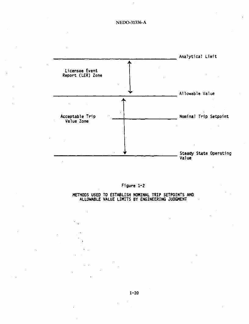
A two-zone concept is suggested as adequate to establish the nominal trip
setpoint and technical specification limit values. The zones specify
ranges within which the trip value is adequate for its intended function.
The acceptable trip value zone is a portion of the instrumentation triprange which will have as its midpoint the nominal trip setpoint. The two
end points of the zone will be chosen as (1) the allowable value, and
(2) a value that will assure spurious trips are avoided. The acceptable
trip value zone must be wide enough to allow for normal instrument drift
between surveillance intervals.
The LER zone is the portion of the instrumentation trip range beyond the
technical specification limit. The LER zone should be established so that
when the maximum expected drift has occurred, sufficient margin remains
between the technical specification limit and the analytical limit to
compensate for instrumentation and calibration accuracies.
An example of the use of engineering judgment where it is not practical to
apply computational techniques is the intermediate range monitor (IRM)
Neutron Flux Scram. The IRM Neutron Flux Scram exists to shut down the
reactor if neutron flux is increasing at a rate that cannot be followed by
the operator. There is no analytical basis for differentiating between
the nominal trip setpoint and the technical specification limit. A
nominal trip setpoint value of 120 divisions is selected to utilize the
maximum range of the instrument. This adequacy of selection has been
demonstrated through field experience. Allowances for instrument drift
are made by providing a two division margin between the nominal trip
setpoint and the technical specification limit (122 divisions).
1-19
NEDO-31336-A
Licensee EventReport (LER) Zone
Acceptable TripValue Zone
Analytical Limit
Allowable Value
Nominal Trip Setpoint
Steady State OperatingValue
Figure 1-2
METHODS USED TO ESTABLISH NOMINAL TRIP SETPOINTS ANDALLOWABLE VALUE LIMITS BY ENGINEERING JUDGMENT
1-20
NEDO-31336-A
1.2.5 Methods Used to Establish Nominal Trip Setpoints and Technical
Specification Limits by Historical Data
A number of setpoints have non-critical functions, or are intended to
provide trip actions related to gross changes in the process variable.
These setpoint values have been historically established as acceptable,
both for regulatory and operational requirements. The continued recom-
mendation of these historically accepted setpoint values is a third method
for establishing nominal trip setpoint and technical specification limit
values. This method is applicable when no analytical limit exists. This
approach is only valid where the governing conditions remain essentially
unaltered from those imposed previously and where the historical values
have been adequate for their intended functions.
One way of establishing the technical specification limit, when the
nominal trip setpoint is a historically accepted value, is to establish
the differential between the nominal trip setpoint and the technical
specification limit as the maximum drift permitted between surveillance
intervals.
An example of the use of historical data is the Main Steamline Radiation
Monitor (MSLRM). The current nominal trip setpoint value (3.0 times full
power background) has been established by the NRC. This value is generally
accepted as being more than sufficiently low enough to detect a gross
release of radioactivity from the core. Allowances for instrument drift
are made between the nominal trip setpoint and the technical specification
limit (3.6 times full power background).
1-21

NEDO-31336-A
1.3 CONCLUSION
The determination of instrument setpoints is a disciplined multi-step
process which applies conservative methodology at each step to assure
positive safety margins. The systematic approach provides assurance that
instrumentation uncertainties are recognized and accounted for in design,
analysis, and application.
1-22
NEDO-31336-A
2.0 INSTRUMENT ACCURACY AND DRIFT METHODOLOGY
2.1. INTRODUCTION
The purpose of this section is to describe the calculations used by
General Electric to validate instrument accuracy and drift values against
system requirements. This methodology is based on the use of Rosemount
(1151, 1152-T0280, 1153 Series B, 1154) or Gould (3018, 3200, 3218) trans-
mitters with Rosemount (510) trip units. It may also be applied to
devices whose performance and application match those of Rosemount and
Gould.
2.2 METHODOLOGY USED TO VALIDATE INSTRUMENT ACCURACY AND DRIFT VALUES
2.2.1 Definitions
System requirements are generally defined in terms of channel (loop)
values:
DL = Channel (Loop) Instrument Drift
AL = Channel (Loop) Instrument Accuracy
CL = Channel (Loop) Calibration Accuracy
2-1

NEDO-31336-A
2-2

NEDO-31336-A
2.2.2 Temperature Effect on Transmitter Accuracy and Drift
In reviewing General Electric Environmental Interface Specifications, thefollowing data were found on the normal temperature range for trans-mitters:
A.
B.
Generic BWR 4/5 - 400 to 1040FGeneric BWR/6 - 400 to 90OF
2-3

NEDO-31336-A
2-4

NEDO-31336-A
2.2.3 Transmitter Accuracy
2-5

NEDO-31336-A
2-6

NEDO-31336-A
2.2.4 Trip Unit Accuracy
2-7

NEDO-31336-A
2.2.5 Transmitter Drift
2-8

NEDO-31336-A
2.2.6 Trip Unit Drift
2-9
NEDO-31336-A
2.3 ADDITIONAL DEVICES IN INSTRUMENT CHANNEL
2-10

NEDO-31336-A
2.4 STATIC PRESSURE EFFECT ON TRANSMITTER ACCURACY (ROSEMOUNT AND GOULD)
2-11
NEDO-31336-A
2.5 SEISMIC EFFECT ON TRANSMITTER ACCURACY (ROSEMOUNT AND GOULD)
2-12
NEDO-31336-A
2.6 RADIATION EFFECT ON TRANSMITTER ACCURACY (ROSEMOUNT AND GOULD)
2-13
NEDO-31336-A
2.7 TEMPERATURE EFFECT ON TRANSMITTER ACCURACY AND DRIFT (GOULD)
2-14

NEDO-31336-A
2-15/2-16

NEDO-31336-A
3.0 INSTRUMENT SETPOINT DESCRIPTIONS
The following section contains descriptions of the instrument functions
for which credit is taken in the FSAR Chapter 6 or 15 analyses. Each
subsection contains discussion of the purpose of the instrument, the trip
logic initiated by the instrument, how the setpoint is calculated, the
analysis that takes credit for the trip, and the assumptions made in the
setpoint determination or analysis.
3- 1/3-Z

NEDO-31336-A
3.1 REACTOR WATER LEVEL 1
3.1.1 Purpose
Level 1 is used to generate initiation signals of low pressure Emergency
Core Cooling Systems (ECCS). Under postulated Loss-of-Coolant Accident
(LOCA) conditions that could result in abnormally low vessel water levels,
fuel cladding integrity must be assured. These trip signals are set high
enough to allow time for the low pressure core flooding systems to activate
or the reactor vessel to depressurize, if necessary, by activating the
Automatic Depressurization System (ADS). The Level 1 setpoint is also low
enough that decreases in level resulting from an operational transient will
not reach it, even with an additional single failure, (e.g., loss of
feedwater flow with a High Pressure Coolant Injection [HPCI]/ High Pressure
Core Spray [HPCS] failure).
In the event of a large break, where the reactor has depressurized to
within the low pressure systems capability, the ECCS functions initiated at
Level 1 are the Low Pressure Core Spray (LPCS)/Core Spray (CS) System and
the Low Pressure Coolant Injection (LPCI) function of the Residual Heat
Removal (RHR) System. ADS initiation is permitted only after the con-
ditions as outlined in Section 3.9 are met. ADS activation reduces reactor
pressure and allows subsequent opening of the LPCS and LPCI injection
valves which introduce water to cool the core. A Level 1 trip also sends
signals to: (1) close the Main Steam Isolation Valves (MSIVs); (2)
disconnect non-Class 1E equipment connected to Class 1E power sources; (3)
provide initiation signals to start the diesel-generators which serve as
standby AC power sources. For Clinton, Perry and Grand Gulf, Level 1
contributes to the initiation of the suppression pool makeup system to add
water to the suppression pool and provide a permissive for containment
spray initiation.
*The terms LPCS and HPCS apply to BWR/5 and BWR/6 core spray functions.Core Spray (CS) and HPCI are terms used to reference similiar functionsfor BWR/4 plants.
3-3

NEDO-31336-A
Level transmitters are utilized to measure differential pressure, an
inverse function of reactor vessel water level, to provide an electrical
outputs to associated trip units. When the magnitude of the output results
in trip signals, the aforementioned functions will be activated on
completion of the logic sequence described below.
3.1.2 Trip Logic Description
A sufficient number of Level 1 trip signals must occur within a particular
division to ensure that the functions associated with that division will be
performed. For those level transmitters providing signals to RHR and
CS/LPCS initiation functions, two-out-of-two levels or one-out-of-two-
twice mixed (level/drywell pressure) logic is employed, wherein two level
instruments or one level and one pressure instrument in one division must
sense a trip signal. The MSIV closure functions, associated with
additional transmitters, are also controlled by one-out-of-two-twice logic.
In this case, a trip unit in either Channel A or C and a trip unit in
either Channel B or D must give a Level 1 trip signal. The ADS logic
requires (N-of-N) in each ADS subsystem (i.e., all level sensors in one
division must agree).
3.1.3 Setpoint Calculations
The instrument setpoint calculation follows the methodology described in
Section 1. The system engineer assigns values to the instrument channel
accuracy, calibration and drift, based on knowledge of system requirements
and instrumentation capabilities. The accuracy and drift are then
confirmed using the methods outlined in Section 2. Process Measurement
Accuracy (PMA) and Primary Element Accuracy (PEA) are calculated based on
the instrument layout. These values (trip accuracy, drift, calibration,
PMA, and PEA) are used in calculating the Allowable Value (AV), and the
Nominal Trip Setpoint (NTSP) from the Analytical Limit (AL) per the
procedure described in Section 1. The results are presented in Table 3.1-1
for a typical plant. The probability of Licensee Event Report (LER)
3-4
NEDO-31336-A
avoidance is then calculated using the methods described in Section 1.
Appropriate Level 1 spurious trip avoidance probabilities must be confirmed
for loss of feedwater with coincident HPCI/HPCS failure and the Anticipated
Transient Without Scram (ATWS) MSIV closure events. Initial data required
in either the setpoint calculation or the determination of trip avoidance
probabilities include the following:
Analytical Limit (AL): The limit is specified as approximately 12
inches above the Top of Active Fuel (TAF), so that the Peak Clad
Temperature (PCT) does not exceed 2200*F. The Design Basis Event
(DBE) is the limiting break of the recirculation line.
Operational Limit: The operational limit is determined from analysis
of two transients. The first is a loss of all feedwater flow, conser-
vatively evaluated with an equipment failure in the HPCS/HPCI System
so that makeup water is supplied only by the Reactor Core Isolation
Cooling (RCIC) System. The second transient is an ATWS MSIV closure.*
3.1.4. Analysis
For the Design Basis Event, the SAFE, REFLOOD, and CHASTE models (NRC
approved licensing evaluation models used in the FSAR analysis) are used to
predict the PCT. These models use water level analytical limits to
simulate when the safety actions are performed. The results are presented
in Table 3.1-1 for a typical plant. Analysis shows that, even if waterlevel recedes beneath the Level 1 Analytical Limit to the transmitter vari-
able leg tap, the PCT will not exceed the prescribed 2200*F limit. The SAFE
computer code model is also used to predict the minimum water level for
*The ATWS MSIV closure event applies only to trip avoidance calculationsHope Creek, Limerick, Nine Mile Point 2 and Perry plants.
3-5
NEDO-31336-A
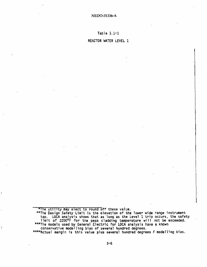
Table 3.1-1
REACTOR WATER LEVEL 1
'The utility may elect to round off these value.**The Design Safety Limit is the elevation of the lower wide range instrument
tap. LOCA analysis shows that as long as the Level 1 trip occurs, the safetylimit of 2200*F for the peak cladding temperature will not be exceeded.
**'The models used by General Electric for LOCA analysis have a knownconservative modelling bias of several hundred degrees.
""Actual margin is this value plus several hundred degrees F modelling bias.
3-6

NEDO-31336-A
loss of all feedwater flow with coincident HPCS/HPCI failure. Inputs to
the analysis assume initial reactor conditions at 105% nuclear boiler ratedsteam flow. RCIC flow is assumed to activate at the Level 2 analytical
limit after the maximum specified RCIC system delay (typically 30 seconds).
ATWS water level behavior is modelled with the REDY computer
approved licensing evaluation model used in FSAR analysis).
prediction, in association with the ECCS initiation logic isATWS design criteria.
code (NRC
This ATWS
used as an
3.1.5. Assumptions and Uncertainties
The following assumptions are made in the setpoint determination:
(1)
(2)
3-7

NEDO-31336-A
(3)
(4)
(5)
(6)
3-8
NEDO-31336-A
3.2 REACTOR WATER LEVEL 2
3.2.1 Purpose
A Level 2 trip indicates that a reactor transient or Loss of Coolant
Accident (LOCA) is occurring, with an associated water level drop.
Functions initiated by Level 2 trip consist of Recirculation Pump Trip
(RPT),* Reactor Core Isolation Cooling (RCIC) System, and High Pressure
Coolant Injection (HPCI) System or High Pressure Core Spray" (HPCS)
System and closure of some of the primary system and containment isolation
valves. The Redundant Reactivity Control System (RRCS) is also initiated
for plants required to address for Anticipated Transient Without Scram
(ATWS).
The Level 2 setpoint is high enough that for complete loss of feedwater
flow the RCIC system flow will be sufficient to avoid initiation of low
pressure Emergency Core Cooling Systems (ECCS) at Level 1. RCIC alone
is assumed to operate (failure of HPCI/HPCS), since it is the most limiting
inventory supply system initiated on Level 2. The setpoint is also low
enough that, after a scram caused by a Level 3 trip with no loss of feed-
water flow, the RCIC and HPCS/HPCI systems will not be initiated.
Level transmitters are utilized to measure differential pressure (an
inverse function of reactor vessel water level) to provide electrical
outputs to associated trip units. When the magnitude of the output results
in trip signals, the aforementioned functions will be activated on comple-
tion of the logic sequence described as follows.
*Plants that have Redundant Reactivity Control System (RRCS) do not have aseparate Recirculation Pump Trip, it is performed by RRCS. Plants withRRCS include Limerick, Nine Mile Point 2, Perry, Hope Creek and GrandGulf (after first refueling).
**HPCI functions at Level 2 apply to all BWR 4 plants. HPCS applies toBWR/5 and BWR/6 plants.
3-9

NEDO-31336-A
3.2.2 Trip Logic Description
A sufficient number of Level 2 tripsignals must occur within a particular
division to ensure that the functions associated with that division will be
performed. Signals required to initiate RPT, RCIC, HPCS and HPCI functions
use one-out-of-two taken twice logic; two-out-of-two logic is used to
initiate RRCS. The logic for containment isolation varies depending upon
the system.
3.2.3 Setpoint Calculations
The instrument setpoint calculations follow the methodology described in
Section 1. The system engineer assigns values to the instrument channel
accuracy, calibration accuracy and drift, based on knowledge of system
requirements and instrumentation capabilities. The accuracy and drift are
then confirmed using the methods outlined in Section 2. Process Measure-
ment Accuracy (PMA) and Primary Element Accuracy (PEA) are calculated based
on the type of instrument supplied and instrument layout. These values
(trip accuracy, drift, calibration, PMA, and PEA) are used in calculating
the Allowable Value (AV) and the Nominal Trip Setpoint (NTSP) from the
Analytical Limit (AL) and an example is given in 3.2-1. The probabilities
of Licensee Event Report (LER) and spurious trip avoidance are then
calculated using the methods described in Section 1. Initial data required
in the setpoint calculation or the determination of the trip avoidance
includes the following:
Analytical Limit: The limit is specified so that the volume of water
at Level 2 is sufficient coupled with action of RCIC (the most limi-
ting inventory supply system initiated on Level 2) for transients
involving loss of all normal feedwater flow to avoid initiation of low
pressure systems at Level 1. The Level 2 setpoint is used in Loss of
Coolant Accident (LOCA) analysis, and the Maximum Average Planar Heat
Linear Generation Rate (MAPLHGR) is set so that the Peak Clad Tempera-
ture (PCT) remains below the appropriate safety limit of 22000 F. The
Design Basis Event (DBE) is the limiting break of the recirculation
line.
3-10

NEDO-31336-A
Table 3.2-1
REACTOR WATER LEVEL 2
*The models used by General Electric for LOCA analysis have a knownconservative modelling bias of several hundred degrees.
*"Actual margin is this value plus several hundred degrees F modelling bias.
3-11
NEDO-31336-A
Operational Limit: The operational limit is the minimum water level
established from analysis of a turbine trip or generator load rejec-
tion (the limiting operational transient).
3.2.4 Analysis
For the Design Basis Event the SAFE, REFLOOD and CHASTE computer code
models (NRC approved licensing evaluation models used in the FSAR analysis)
are used to predict the PCT following a simulated scram at the Level 3
analytical limit and ECCS injections at appropriate Level 2 and Level 1
analytical limits. Since the DBE for Level 2 is the same as for Level 1,
the bounding values provided in Table 3.2-1 for a sample plant are the same
values reported for Level 1.
The ATWS analysis is also performed assuming the appropriate trip actions
(detailed in Section 3.6) are initiated at the Level 2 analytical limit.
The REDY code (NRC approved licensing evaluation model used in FSAR
analysis) is used to simulate the transient.
3.2.5 Assumption and Uncertainties
The following assumptions are made in the setpoint determination:
(1)
3-12

NEDO-31336-A
(,-,)
(3)
3-13

NEDO-31336-A
(4)
(5)
(6)
3-14
NEDO-31336-A
3.3 REACTOR WATER LEVEL 3
3.3.1 Purpose
A Level 3 trip indicates that the water level in the reactor vessel has
dropped, and a continued decrease in level would cause steam to bypass the
seal skirts of the separators or dryers. Generally, this is indicative of
a significant problem with the level control system or reactor feedwatersystem. Under these circumstances, reactor scram is initiated by a Level
3 Reactor Protection System (RPS) trip to substantially reduce steam
production. The Reactor Water Cleanup system is isolated when a Level 3
trip signal is received. If the Residual Heat Removal (RHR) system is
operating in the shutdown cooling mode, the isolation valves on the RHR
system suction piping are also closed to prevent further loss of vessel
water inventory via that path. Level 3 trip also serves as a permissive
signal for initiation of the Automatic Depressurization System (ADS) to
allow activation of the low pressure Emergency Core Cooling Systems (ECCS).The Level 3 signal provides confirmation that the reactor vessel water
level is low; ADS is not activated until Level 1 is reached.
Level transmitters are utilized to measure differential pressure, an
inverse function of reactor vessel water level and provide an electrical
outputs to associated trip units. When the magnitude of the output results
in trip signals, the aforementioned will be activated on completion of the
logic sequence described below.
3.3.2 Trip Logic Description
A sufficient number of Level 3 trip signals must occur within a particular
division to initiate the functions associated with that division. Level
transmitters corresponding to ADS functions use one-out-of-two logic,
wherein either instrument in the 2 divisions of ADS must sense a trip
signal. The RPS functions are associated with four additional transmitters
that employ one-out-of-two-twice logic. In this case, a transmitter in either
3-15
NEDO-31336-A
Channel A or A and a transmitter in either Division B or B must receive1 2 1 2a Level 3 trip signal to initiate the RPS functions for BWR/4 and BWR/5
plants and channels A or C and B or D for BWR/6 plants. For Clinton, (the
only solid state plant), the RPS logic is two-out-of-four. The isolation
valves are closed after receipt of two-out-of-two Level 3 signals in either
division.
3.3.3 Setpoint Calculations
The instrument setpoint calculations follow the methodology described in
Section 1. The system engineer assigns values to the instrument channel
accuracy, calibration accuracy and drift, based on knowledge of system
requirements and instrumentation capabilities. The accuracy and drift are
then confirmed using the methods outlined in Section 2. The Process
Measurement (PMA) and Primary Element Accuracies (PEA) are calculated based
on the instrument layout. These values (trip accuracy, drift, calibration,
PHA and PEA) are used in calculating the Allowable Value (AV) and the
Nominal Trip Setpoint (NTSP) from the Analytic Limit (AL) using the
methodology in Section 1. The probabilities of LicensiRg Event Report
(LER) avoidance and spurious trip avoidance are then calculated using the
methods described in Section 1. An example is presented in Table 3.3-1.
Initial data required in the setpoint calculation or the determination of
trip avoidance probabilities include the following:
Analytical Limit: Specified so that during normal operation seal
skirts of the separators and dryers are not uncovered and so that the
quantity of coolant following a Level 3 scram is sufficient (coupled
with actions of other inventory supply systems) for transients
involving loss of all normal feedwater flow to avoid initiation of the
low pressure ECCS systems at Level 1. The Level 3 setpoint is used in
Loss of Coolant Accident (LOCA) analysis, which determines the MaximumAverage Planar Linear Heat Generation Rate (MAPLHGR). This assures
that the Peak Clad Temperature (PCT) remains below the appropriate
safety limit. The Design Basis Event (DBE) is the limiting break of
the recirculation line.
3-16
NEDO-31336-A
Table 3.3-1
REACTOR WATER LEVEL 3
*The models used by General Electric for LOCA analysis have a knownconservative modelling bias of several hundred degrees.
*"Actual margin is this value plus several hundred degrees F modelling bias.
3-17
NEDO-31336-A
Operational Limit (OL): The OL is the minimum water level established
from analysis of the limiting operating transient, corresponding to
one feedwater pump trip.
3.3.4 Analysis
For the DBE, the SAFE, REFLOOD and CHASTE computer code models (NRC
approved licensing evaluation models used in the FSAR analysis) are used to
predict the PCT following a simulated scram at Level 3 analytical limit and
ECCS injections at appropriate Level 2 and Level 1 analytic limits.
Analysis shows that, even if water level recedes beneath the Level 1
analytical limit to the variable leg tap, the PCT will not exceed the
prescribed 2200°F safety limit. The inputs to the analysis assume initial
reactor conditions at 105% nuclear boiler rated steam flow. The Low
Pressure Coolant Injection system (LPCI) injection valve is assumed to fail
(the limiting single failure).
3.3.5 Assumptions and Uncertainties
The following assumptions are made in the determination of the setpoint:
(1)
(2)
3-18

NEDO-31336-A
(3)
(4)
(5)
(6)
3-19/3-20
NEDO-31336-A
3.4 REACTOR WATER LEVEL 8
3.4.1 Purpose
A Level 8 trip signal indicates that the reactor water level in the vessel
has increased and protective actions are initiated to prevent further
vessel overfill. The trip signal is selected low enough to protect the
turbine against gross carryover of moisture and to provide adequate core
thermal margins during abnormal events. Functions activated with this
signal include closure of main turbine valves, trips of reactor feedwater
pumps or turbines (depending upon feedwater system design), trip of Reactor •
Core Isolation Cooling (RCIC) system and trip of High Pressure Coolant
Injection (HPCI) or High Pressure Core Spray (HPCS) Systems . Reactor
scram by the Reactor Protection System (RPS) may also be included in the
Level 8 trip actions so that the Minimum Critical Power Ratio (MCPR) ismaintained above the safety limit MCPR, especially during the feedwater
controller failure (maximum demand) transients.
The Level 8 signals are generated from two different reactor water level
measurement systems. They are the narrow water range which has a range of
60 inches (or approximately Level 3 to above Level 8) and the wide water
range which has a range of 210 or 220 inches (or approximately top of
active fuel to above Level 8). The trip actions that are performed by each
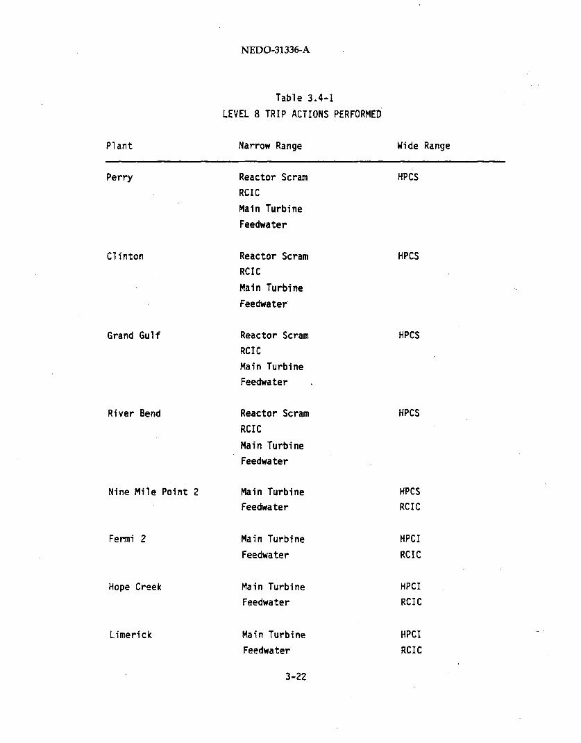
water level measurement system are outlined in Table 3.4-1.
Level transmitters are utilized to measure differential pressure, an
inverse function of reactor vessel water level, and to provide electrical
outputs to associated trip units. When the magnitude of the output results
in trip signals, the aforementioned functions will be activated in accor-
dance with the initiation logic described as follows.
*HPCS is applicable to BWR/5 and BWR/6 plants, KPCI is for BWR/4 plants."*Direct scram at Level 8 occurs only for BWR/6. BWR/4 and BWR/5 plants
receive a scram signal from the main turbine trip.
3-21
NEDO-31336-A
Plant
Perry
Clinton
Grand Gulf
River Bend
Nine Mile Point 2
Fermi 2
Hope Creek
Limerick
Table 3.4-1
LEVEL 8 TRIP ACTIONS PERFORMED
Narrow Range
Reactor Scram
RCIC
Main Turbine
Feedwater
Reactor Scram
RCIC
Main Turbine
Feedwater
Reactor Scram
RCIC
Main Turbine
Feedwater
Reactor Scram
RCIC
Main Turbine
Feedwater
Main Turbine
Feedwater
Main Turbine
Feedwater
Main Turbine
Feedwater
Main Turbine
Feedwater
3-22
Wide Range
HPCS
HPCS
HPCS
HPCS
HPCS
RCIC
HPCI
RCIC
HPCI
RCIC
HPCI
RCIC
NEDO-31336-A
3.4.2 Trip Logic Description
A sufficient number of Level 8 trip signals must occur within a particular
division to ensure that the functions associated with that division will be
performed. For those level transmitters corresponding to both RCIC and
HPCI/HPCS functions, two-out-of-two logic is employed; plants with Redun-
dant Reactivity Control System (RRCS) use one-out-of-two-twice logic.
Main turbine stop valve and feedwater pump/turbine trips utilize
two-out-of-three logic (except Fermi 2 and Limerick which uses
one-out-of-two-twice logic). Reactor scram (RPS) functions for BWR/6
plants only, are initiated with one-out-of-two-twice logic (i.e., channel A
or C and channel B or D must sense a trip signal). Clinton uses
two-out-of-four logic for the scram function.
3.4.3 Setpoint Calculations
The instrument setpoint calculations follow the methodology described in
Section 1. The system engineer assigns values to the instrument channel
accuracy, calibration and drift, based on knowledge of system requirements
and instrumentation capabilities. The accuracy and drift are then
confirmed using the methods in Section 2. Process Measurement Accuracy
(PMA) and Primary Element Accuracy (PEA) are calculated based on the
instrument layout. These values (trip accuracy, drift, calibration, PMA
and PEA) are used in calculating the Allowable Value (AV) and the Nominal
Trip Setpoint (NTSP) from the Analytical Limit (AL). The probabilities of
Licensee Event Report (LER) avoidance and spurious trip avoidance are then
calculated using the methods in Section 1. An example is presented inTable 3.4-2. Initial data required in the setpoint calculation or the
determination of trip avoidance probabilities include the following:
*The RRCS plants are Hope Creek, Limerick, Nine Mile Point 2, and Perry.
3-23
NEDO-31336-A
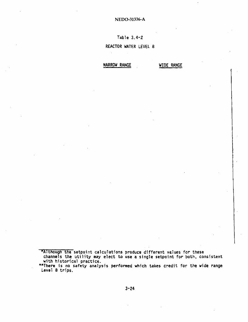
Table 3.4-2
REACTOR WATER LEVEL 8
NARROW RANGE WIDE RANGE
*Although the setpoint calculations produce different values for thesechannels the utility may elect to use a single setpoint for both, consistentwith historical practice.
*"There is no safety analysis performed which takes credit for the wide rangeLevel 8 trips.
3-24
NEDO-31336-A
Analytical Limit: Specified at approximately the top of the steam
separators near the upper limit of the region where acceptable steam
carryover occurs. The Design Basis Event (DBE) is the feedwater
controller failure transient postulated on the basis of a single
failure of a control device that can directly cause an increase in
coolant inventory by increasing the feedwater flow. The most severe
applicable event is a feedwater controller failure to maximum flow
demand, where the feedwater controller is forced to its upper limit at
the beginning of the event.
Operational Limit: The maximum water level during the limiting
operational transient which results from trip of one recirculation
pump.
3.4.4 Analysis
The DBE was analyzed with the REDY computer code for Clinton and the ODYN
code (NRC approved licensing evaluation models used in the FSAR analysis)
for other plants. The transient is initiated from 105% Nuclear Boiler
Rated (NBR) steam flow for all plants except Fermi 2 which is initiated
from 102% NBR power. Feedwater flow is increased to its upper limit at the
start of the transient to represent the simulated failure of the feedwater
controller. Appropriate delays due to sensor and logic are considered in
the evaluation. The improved SCAT and ISCOR codes (NRC approved licensing
evaluation models used in the FSAR analysis) are used to determine the
Minimum Critical Power Ratio (MCPR) during the transient and demonstrate
adequate margin to the Safety Limit MCPR.
3-25

NEDO-31336-A
3.4.5 Assumptions and Uncertainties
The following assumptions are made in the setpoint determination:
(1)
(2)
(3)
3-26

NEDO-31336-A
(4)
(5)
(6)
3-27/3-28
NEDO-31336-A
3.5 REACTOR VESSEL HIGH PRESSURE
3.5.1 Purpose
The reactor vessel pressure must be maintained within the limits pre-
cribed by the ASME Boiler & Pressure Vessel Code, Section III. If pressure
rises to a preset high value, a trip signal to the Reactor Protection
System (RPS) will initiate reactor scram to shut down nuclear heat gener-
ation. Reactor scram is initiated by high pressure if other signals have
failed to scram the reactor to limit the effect of positive pressure on
reactor power and provide assurance that reactor vessel integrity will be
maintained.
3.5.2 Trip Logic Description
The reactor vessel steam dome pressure-is monitored by four pressure
transmitters. There are a total of four trip units providing a high
pressure trip; (one'each for channels A, B, C and D, for BWR/6 plants and
A1, A2, B1, and B2 is the designation used for BWR/4 and 5 plants). The
trip logic for reactor scram is arranged in one-out-of-two-twice logic
except for Clinton which has two-out-of-four logic to perform the trip
function.
3.5.3 Setpoint Calculation
The instrument setpoint calculations follow the methodology described by
Section 1. The system engineer assigns values to instrument channel
accuracy, calibration accuracy, and drift based on a knowledge of the
system requirements and instrumentation capabilities. The accuracy and
drift are then confirmed using the methods in Section 2. Process
Measurement Accuracy (PMA) and Primary Element Accuracy (PEA) are also
determined.
3-29

NEDO-31336-A
The Allowable Value (AV) and Nominal Trip Setpoint (NTSP) are then calcu-
lated using the methods described in Section 1. The probabilities of
Licensee Event Report (LER) and spurious trip avoidance are also
calculated, using the methods described in Section 1. An example ispresented in Table 3.5-1. The operational limit for spurious trip
avoidance is established from analysis of a turbine control system pressureregulator switching event (the limiting operational transient).
3.5.4. Analysis
The Design Basis Event (DBE) for the high pressure scram setpoint is the
closure of the Main Steam Isolation Valves (MSIVs) with pressure scram.The normal scram path associated with MSIV position switches and high
neutron flux are assumed failed.
The ODYN code (NRC approved licensing evaluation model used for the FSAR
analysis) is used to simulate this transient. The transient is initiatedfrom 105% Nuclear Boiler Rated (NBR) steam flow, and a conservative closure
time of 3 seconds is utilized (compared to a nominal range of 3 to 5
seconds). An appropriate maximum scram delay (sensor plus logic) time is
also included in the ODYN simulation.
3.5.5 Assumptions and Inaccuracies
The following assumptions are made in the setpoint calculations:
(1)
(2)
3-30
NEDO-31336-A
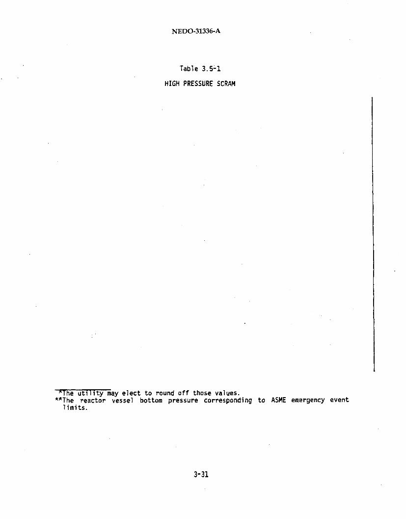
Table 3.5-1
HIGH PRESSURE SCRAM
5The utility may elect to round off those values.*"The reactor vessel bottom pressure corresponding to ASME emergency event
limits.
3-31

NEDO-31336-A
(3)
(4)
(5)
(6)
3-32
NEDO-31336-A
3.6 REACTOR VESSEL HIGH PRESSURE ATWS RPT
3.6.1 Purpose
In the event of assumed failure of the normal scram paths associated with
the Reactor Protection System (RPS) vessel high pressure trip, the Main
Steam Isolation Valve (MSIV) position switches and the high neutron flux
trips, the Reactor Pressure Vessel (RPV) high steam dome pressure
Anticipated Transient Without Scram Recirculation Pump Trip (ATWS RPT)
signal is initiated (if reactor pressure rises to a preset high value).
This signal also does the following for Limerick, Perry, Hope Creek, and
Nine Mile Point 2, which are equipped with the Redundant Reactivity Control
System (RRCS):
(1) Initiates Alternate Rod Insertion (ARI).
(2) Contributes to initiation (after a time delay) of feedwater flow
runback.
(3) Contributes to initiation (after a time delay) of the Standby Liquid
Control System (except Perry with manual initiation) and isolation of
the Reactor Water Cleanup System (RWCU).
For Fermi 2, Clinton and Grand Gulf*, the high pressure signal initiates
ARI and RPT only.
The trip of the recirculation pumps early in the event will result in
reduction of core flow which creates voids, thereby reducing the power
generation.
ARI to be installed at a later date at Grand Gulf.
3-33
NEDO-31336-A
3.6.2 Trip Logic Description
There are four pressure transmitters and trip devices which provide the
protective trip function. Each pressure transmitter functions as part of a
circuit that monitors reactor vessel steam dome pressure and provides a
trip signal in its assigned electrical division (except River Bend, Clinton
and Grand Gulf , which do not use assigned divisional power) if the
pressure rises to a predetermined high value. The presence of two such trip
signals in the same electrical division will:
(1) Trip recirculation pumps (for Limerick, River Bend, Clinton,
Fermi 2, Hope Creek plants and Grand Gulf* design).
or
(2) Trip recirculation pumps from the normal power supply, which
transfers input power to the low-frequency motor-generator (LFMG)
sets, and then will trip the recirculation pumps from the
LFMG sets after a time delay if the Average Power Range Monitors
(APRMs) still read high (for Perry, and Nine Mile Point 2 ).
3.6.3 Setpoint Calculation
The instrument setpoint calculation follows the methodology described in
Section 1. The system engineer assigns values to the instrument channel
accuracy, calibration, and drift, based on knowledge of the instrument
capabilities and system requirements. The instrument accuracy and drift
values are then confirmed using the the methods outlined in Section 2.
Analysis is also performed to determine the Process Measurement Accuracy
(PMA) and Primary Element Accuracy (PEA). These values are then used to
determine the Allowable Value (AV), and the Nominal Trip Setpoint (NTSP)
from the Analytical Limit (AL). An example is given in Table 3.6-1. The
probabilities of spurious trip avoidance and Licensee Event Report (LER)
avoidance are also calculated using the methods described in Section 1.
The current and future Grand Gulf design provides that either of the twotrip signals per trip system will enable the safety function of the tripsystem.
3-34
NEDO-31336-A
Table 3.6-1
REACTOR VESSEL HIGH PRESSURE ATWS RPT
'The utility may elect to round off this value."*The reactor vessel bottom pressure corresponding to ASME emergency event
limits for active components. For passive components the maximum pressurelimit is 1500 psig.
3-35
NEDO-31336-A
3.6.4 Analysis
The Design Basis Event for the ATWS RPT setpoint is the Main Steam
Isolation Valve (MSIV) closure with a failure to scram. The normal scram
paths associated with MSIV position switches, high neutron flux and high
dome pressure are assumed to have failed. The safety limit is peak
pressure at the RPV bottom of 1375 psig for active components, and 1500
psig for passive components.
The REDY code (NRC approved licensing evaluation model used in FSAR
analysis) is used to simulate this transient. The initial condition is
100% Nuclear Boiler Rated (NBR) steam flow. A nominal four second MSIV
closure time is used.
The ATWS analyses for four of the plants (Perry, Nine Mile Point 2,
Limerick, and Hope Creek) are plant specific. The River Bend, Grand Gulf
and Fermi 2 results are estimated values based on generic plant analysis
with adjustments for plant specific total relief valve capacities.
3.6.5 Assumptions and Uncertainties
The following assumptions are made in the setpoint determinations:
(1)
(2)
3-36

NEDO-31336-A
(3)
(4)
(5)
(6)
3-37/3-38
NEDO-31336-A
3.7 MAIN STEAM SAFETY/RELIEF VALVE - RELIEF /LOW-LOW SET
3.7.1 Purpose
The main steam Safety/Relief Valves (SRVs) perform several functions. Some
of these functions require a trip signal (from reactor vessel dome pres-
sure) to open and close a sequence of SRVs at valve inlet pressures below
the safety (spring) actuation setpoints.
The first of these trip setpoints is designated as the "relief" setpoint
for BWR/5 and BWR/6 plants that use Crosby and Dikkers valves (Table
3.7-1). On these plants, the relief setpoints are 3 to 5 sequential
values, with one or more valves at each setpoint. One or more valves will
open during reactor pressure transients. The selected setpoints are such
that, for the limiting transients, ASME Code limits on peak vessel pressure
(vessel bottom pressure) will not be exceeded when credit is taken for SRV
actuation.
The second trip setpoint, designated as "Low-Low Set" (LLS) relief
setpoint, is used for all plants (BWR/6) with Mark III containments to
eliminate containment loading due to repeated multiple SRV actuations for
transient events. For Mark I containments (Fermi 2 and Hope Creek), LLS is
designed to assure that after initial opening and closing of SRVs,
actuations will not occur within the time interval required for the SRV
discharge line water leg to decrease to a level such that containmentloading is acceptable. In this case, the intent is to reduce loads on SRV
discharge piping and associated loads on the torus, which can be large
if SRV actuation occurs with a large water leg in the discharge piping.
*BWR/4 plants (Limerick, Fermi 2, and Hope Creek) with Target RockSRVs are considered to perform safety instead of relief functions. Theassociated safety setpoints are discussed in the SRV Safety SetpointSection. Fermi 2 and Hope Creek do have LLS functions which are includedin this report.
3-39

NEDO-31336-A
Table 3.7-1
SAFETY/RELIEF VALVE INFORMATION
BWR Containment SRV Number Low-Low Auto
model MARK Mfr. of SRV Set Relief
Perry 6 Il1 Dikkers 19 Yes Yes
River Bend 6 III Crosby 16 Yes Yes
Clinton 6 IIi Dikkers 16 Yes Yes
Grand Gulf 6 III Dikkers 20 Yes Yes
Nine Mile Point 2 5 II Dikkers 18 No No
Limerick 4 II T/R 14 No No
Fermi 2 4 I T/R 15 Yes No
Hope Creek 4 I T/R 14 Yes No
*Yes indicates plants for which credit has been taken for the relief modeof actuation for ASME code required overpressure protection analysis.
3-40

NEDO-31336-A
Both types of loading are reduced by LLS logic circuitry that arms prese-
lected valves when reactor pressure transients are expected to result in at
least one SRV opening. The LLS logic permits extended vessel depressuriza-
tion cycles through the preselected valves. This results in longer timeý
intervals between subsequent vessel repressurization and valve reopening.
It eliminates or acceptably spreads out subsequent multiple valve
reopenings, thereby reducing containment design loads. In addition, the
LLS feature reduces the required number of SRV cycles, which results in a
reduction of the total containment and SRV fatigue duty cycles.
3.7.2 Trip Logic Description
SRVs with relief functions (Crosby and Dikkers valves) will be opened when
their relief setpoints are exceeded during a pressure transient. For Nine
Mile Point 2 and BWR/6 plants, each group of valves at one setpoint is
ganged together using shared logic. In addition, BWR/6's have redundant
logic. The valves equipped with the LLS functions are also armed to func-
tion at their LLS setpoints as described below.
The LLS arming logic is designed to prevent the valves from prematurely
actuating during normal plant operation, since the opening setpoints for
the LLS function are in the pressure range of normal reactor operation.
For the BWR/6's, the LLS valves are armed after any one SRV receives a
signal to open in the normal relief mode. For Fermi 2, the LLS valves are
armed by coincident signals indicating actuation of any SRV and high
reactor pressure scram. For Hope Creek, the LLS valves are armed by
coincident signals indicating that the high LLS valve setpoint and high
reactor pressure scram setpoint have been reached.
The logic design assures that a single failure shall not prevent any LLS
valve from operating or cause inadvertent seal-in of the LLS logic. Once
LLS is armed, the control logic of the LLS uses the steam dome pressure
instrumentation to electrically control the SRV solenoid valves so that
only the LLS valves open and close at their assigned LLS setpoints. The
3-41

NEDO-31336-A
control logic governs as long as the arming logic remains sealed in. The
logic seal-in is annunciated and remains in effect until the operator
manually resets it.
3.7.3 Setpoint Calculations
3-42
NEDO-31336-A
The instrument accuracy, calibration and drift are assigned values based on
knowledge of the instrumentation and system requirements by the system
engineer. The values for instrument accuracy and drift are confirmed using
the methods in Section 2. The AV and NTSP are then calculated using the
methods in Section 1 and an example is included in Tables 3.7-2 and 3.7-3.The Licensee Event Report (LER) avoidance criterion is also applied
following Section 1.
3.7.4 Analysis
For BWR/6 plants with redundant pressure-sensing logic, the SRV relief
function is part of the reactor overpressure protection system to satisfy
requirements of Section III of the ASME Boiler and Pressure Vessel Code.
The NRC has adopted the ASME Code as part of their requirements in the Code
of Federal Regulations (10CFR5O.55a). Accordingly, limited credit is
allowed for the dual purpose safety/relief valves in their ASME code
qualified modes of relief operation. The appropriate analyses for limiting
SRV transient events and Anticipated Transients Without Scram (ATWS) are
presented separately in the following subsections.
3.7.4.1 Relief Function for Transient Events
For the BWR/6 plants, the overpressure protection analysis is performed
with credit for half of the SRVs opening at the SRV relief function and the
remainder opening at the safety function setpoints. Hence, for these
3-43

NEDO-31336-A
Table 3.7-2
MAIN STEAM SAFETY/RELIEF VALVE - RELIEF SETPOINTS
GROUPIst 2nd , 3rd
"The utility may elect to round off these values.*"The reactor vessel bottom pressure corresponding to ASME moderate frequency
event limits.
3-44
NEDO-31336-A
Table 3.7-3
SRV LOW-LOW SET
2NDOPEN CLOSE
1STOPEN CLOSE
3RDOPEN CLOSE
xThe utility may elect to round off these values."*This safety corresponds to the nominal setpoint of the first group of relief
.valves.
3-45
NEDO-31336-A
plants, the Design Basis Event (DBE) for the SRV relief setpoint is the
most severe vessel overpressure transient event. Both the closure of all
Main Steam Isolation Valves (MSIV) and a turbine/generator trip with bypass
failure are evaluated. The MSIV closure event is slightly more severe when
credit is taken only for indirectly derived scrams, while the
turbine/generator trip with bypass failure is slightly more severe when
credit is taken for direct scram. Hence, the MSIV closure with neutron
flux scram is used as the DBE for the SRV relief setpoint.
For Nine Mile Point 2 (a BWR/5 without redundant relief pressure-sensing
logic), the FSAR overpressure protection analysis is conservatively
performed with credit for the SRV spring safety function only. The DBE for
the SRV relief setpoints for this plant is the generator load rejection
with bypass failure event (FSAR Chapter 15).
These DBEs were analyzed with the REDY computer code for Clinton and with
the ODYN code (NRC approved licensing evaluation models used for FSAR
analysis) for the other plants. The applicability of the River Bend FSAR
ODYN results to Clinton for pressurization transients is justified in the
Clinton FSAR (Section 15.2). Therefore, the River Bend MSIV closure
results are applied to Clinton. The transients were initiated from full
design power conditions of 105% Nuclear Boiler Rated (NBR) steam flow. The
MSIVs are normally specified to close in 3 to 5 seconds. For the analysis,
a conservative closure time of 3 seconds was utilized. Protection func-
tions were modeled at their AL values (e.g., high APRM neutron flux scram
setpoint). A maximum SRV delay time (including pressure sensor, logic plus
valve delay) of 0.4 seconds was also included in the analysis. The results
of the relief function analyses are sunmmarized in Table 3.7-2 for a typical
plant.
3-46
NEDO-31336-A
The SRV functions for the MSIV closure event for overpressure
protection were modeled as follows:
Whenever system pressure increases to the relief pressure setpoint of
a group of valves having the same setpoint, half of those valves are
assumed to operate in the relief mode, opened by the pneumatic power
actuation. When the system pressure increases to the valve spring set
pressure of a group of valves, those valves not already considered
open are assumed to begin opening and to reach full open at 103% of
the valve spring set pressure.
3.7.4.2 LLS Function for Transient Events
The DBE for the SRV LLS setpoint is the MSIV closure event with direct
scram (FSAR Chapter 5). The SAFE computer code (NRC approved licensing
evaluation model used for FSAR analysis) is used to analyze this long term
event. The transient is initiated from 105% NBR steam flow. The analysis
assumes nominal relief setpoints, nominal LLS setpoints for BWR/6s and
analytical limit LLS setpoints for Fermi 2 and Hope Creek, conservative
relief opening and closing response and conservative decay heat. The
results of the LLS function analyses are summarized in Table 3.7-3 for a
typical plant.
3.7.4.3 Relief and LSS Functions for ATWS Events
The main steam SRVs are expected to perform similar functions during
Anticipated Transient Without Scram (ATWS) events as during events with
scram.
The Safety Limits for ATWS pressurization events are chosen to apply
appropriately for active and passive components. General Electric practice
has been to design active components for the pressure to which they will be
exposed or to perform an assurance-of-function review. The critical compo-
nents for this review are the SRVs and the MSIVs. These active components
are limited to 1375 psig. Other active components have higher limits which
3-47
NEDO-31336-A
were shown through assurance-of-function review. Passive components are
limited to Service Level C, ASME Boiler and Pressure Vessel Code, SectionIII.
The ATWS basis is MSIV closure initiated from 100% NBR conditions. This
event has been analyzed with the REDY computer code for Perry, Grand Gulf
and Nine Mile Point 2. ATWS analyses have not been done for River Bend,
Clinton, and Fermi 2. ATWS analyses for Limerick and Hope Creek are
presented in the SRV Safety Setpoint Description. ATWS events are analyzed
with all SRV relief functions operable. Bounding values for ATWS events
were found to be less limiting than the bounding values for transient
events (Subsection 3.7.4.2).
(1) Perry
For Perry ATWS analysis, AL values of relief functions were used for the
initial SRV opening. All SRV closures and subsequent openings were then
modeled to occur at the NTSP values.
(2) Grand Gulf
For Grand Gulf ATWS analysis, AL values of the setpoints were used in all
opening and closing actuations. This was an early analysis and ATWSanalytical procedures were subsequently revised to be more realistic for
subsequent cycles. This deviation will have no significant impact on the
predicted maximum pressure(Bounding Value).
(3) Nine Mile Point 2
For Nine Mile Point 2 ATWS analysis, AL values of the relief functions were
used for the initial opening. All SRV subsequent openings were then
modelled to occur at the NTSP value plus 8 psi. All SRV closures weremodelled to occur at the opening setpoint times the lower limit closing
fraction (0.89).
3-48

NEDO-31336-A
Each group of relief valves at a particular setpoint has two pressure
sensors associated with it. Both sensors for each group must provide a
signal to initiate opening of the entire group (two-out-of-two logic).
Even though both sensors for a group are set at the same setpoint, in
reality they will most likely be spread over some range of values. For the
initial opening, the AL is used for each group. For subsequent openings,
the setpoints of the two sensors for a given group of values is "spread"
around the NTSP by factors based on order statistics and the standard
deviation, and the higher of the two values is used as the opening setpoint
for the entire group (calculated to be 8 psi higher than the NTSP when the
difference between the AL and NTSP values is assumed to be equal to two
standard deviations).
3.7.4.4 LLS Function for LOCA Events
The LLS functions for Fermi 2 and Hope Creek are designed to operate for
LOCA events. A small break LOCA would fill the drywell with steam, so
after each SRV actuation, the vacuum breaker would draw steam instead of
air into the SRV discharge line. Condensation of this steam inside the
discharge line would result in a higher water leg and thus a longer time
for the water leg to return to normal. The vacuum breakers on the SRV
discharge line open to equalize the pressure between the SRV discharge line
and the drywell, allowing the water leg to return to its normal level. SRV
actuation before water level returns to normal could result in high thrust
loads.
This potentially high thrust load condition is accounted in the design of
the SRV LLS setpoints for Fermi 2 and Hope Creek. The LOCA basis event for2these two plants is a small break (0.1 ft ) with loss of offsite power.
The loss of offsite power will result in a loss of power to the MG sets of
the Reactor Protection System, causing reactor isolation and subsequent
pressurization. This event is initiated from full power (105% NBR steam
flow and 104.2% NBR power). The results of this analysis are bounded by
the DBE analysis for SRV LLS setpoints (Subsection 3.7.4.2).
3-49

NEDO-31336-A
The LLS functions of the BWR/6 plants are also designed to operate for LOCA
events. For this class of plants, predicted pool boundary containment
loads due to second or subsequent multiple valve actuations may exceed the
current design basis. Therefore, the LLS logic was designed to eliminate
such subsequent actuations of multiple SRVs. Bounding values for the SRV
LLS setpoints for LOCA events were found to be less limiting than the
bounding values for transient events (Subsection 3.7.4.2).
3.7.5 Assumptions and Uncertainties
The following assumptions are made in the setpoint determination:
(2)
(3)
(4)
(5)
3-50

NEDO-31336-A
(6)
3-51/3-52

NEDO-31336-A
3.8 MAIN STEAM SAFETY/RELIEF VALVE - SAFETY
3.8.1 Purpose
BWR/6's and Nine Mile Point 2 use Crosby or Dikkers Safety/Relief Valves
(SRVs) and BWR/4's have Target Rock SRVs (see Table 3.8-1), to perform the
required pressure relief safety function. The safety function of the SRVs
occurs when steam pressure acting on the valve inlet overcomes the spring
preload that establishes the setpoint pressure. Upon valve actuation, the
reactor primary system high pressure is relieved by discharging steam
through the valves and their discharge lines into the suppression pool.
The reactor primary system pressure is thus maintained within the limits of
Section III of the ASME Boiler and Pressure Vessel Code even in the event
of a high pressure transient condition.
3.8.2 Valve Actuation Mechanism
Two to six SRVs are mounted between the reactor pressure vessel and the
inboard main steam line isolation valves (MSIVs) on each of the four main
steam lines. The actuation mechanism is either direct (at set pressure,
steam pressure opens main disc) or pilot actuated (at set pressure, steam
pressure opens a pilot valve which triggers main valve opening), depending
on the valve design. A description of each actuation mechanism is
presented below.
3.8.2.1 Direct Activation
Crosby and Dikkers SRVs are of the direct acting design. River Bend is
equipped with Crosby valves, while Perry, Clinton, Grand Gulf and Nine Mile
Point 2 have Dikkers valves. These valves have main discs that are loaded
directly by a spring that establishes set pressure to keep the SRVs closed.
When the main steam line static pressure on the valve disc exerts enough
force to overcome the spring preload, the valve opens and remains that way
until the main steam line static pressure drops to the range of 89 to 98%
of the opening pressure, at which point valve reclosure occurs. Relief
3-53
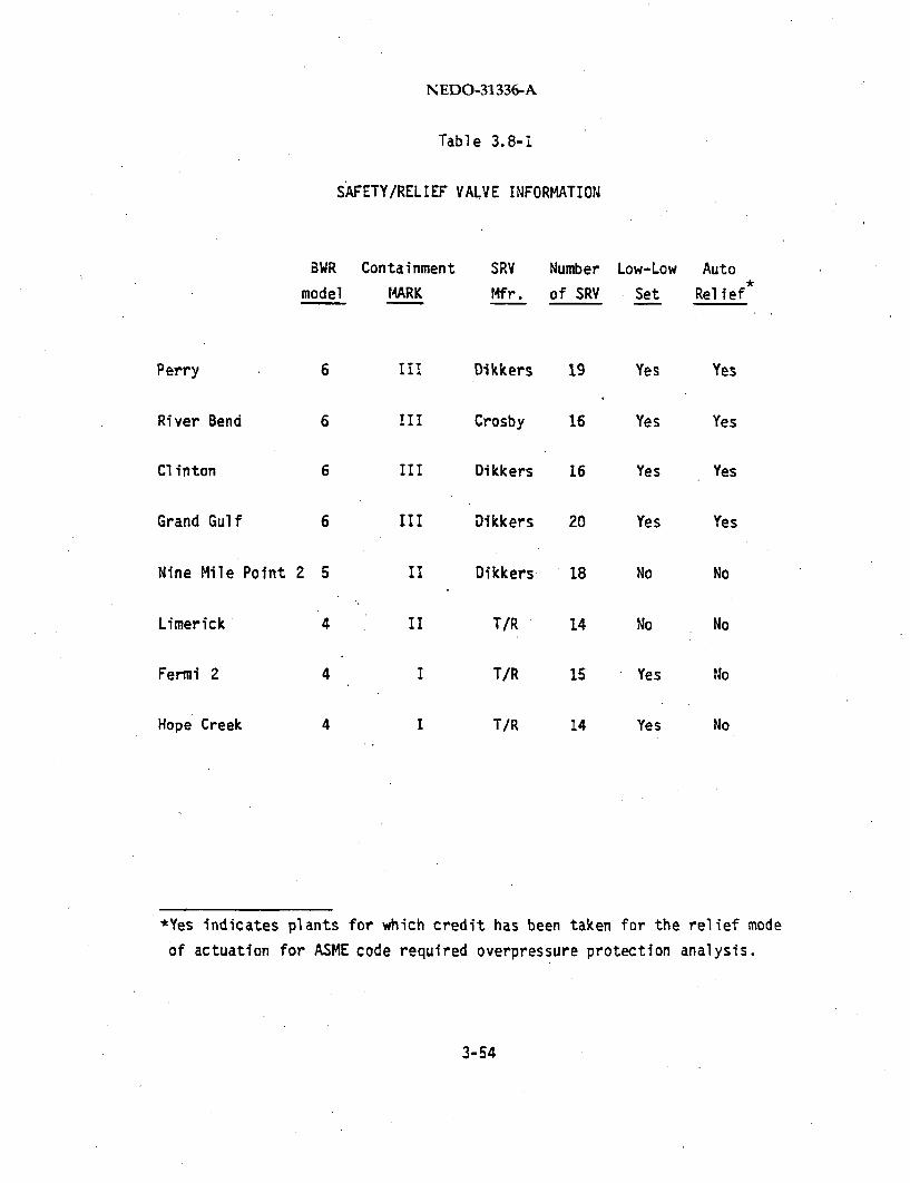
NEDO-31336-A
Table 3.8-i
SAFETY/RELIEF VALVE INFORMATION
BWR Containment SRV Number Low-Low Auto
model MARK Mfr. of SRV Set Relief
Perry 6 I11 Dikkers 19 Yes Yes
River Bend 6 !II Crosby 16 Yes Yes
Clinton 6 III Dikkers 16 Yes Yes
Grand Gulf 6 III Dikkers 20 Yes Yes
Nine Mile Point 2 5 II Dikkers 18 No No
Limerick 4 II T/R 14 No No
Fermi 2 4 I T/R 15 Yes No
Hope Creek 4 I T/R 14 Yes No
*Yes indicates plants for which credit has been taken for the relief mode
of actuation for ASME code required overpressure protection analysis.
3-54

NEDO-31336-A
actuation of these valves covered in a separate discussion, is produced by
an air actuator which opens and closes the valve below the spring actuation
pressures for all high pressure operational transients.
3.8.2.2 Indirect Pilot Activation
Two-stage pilot-operated SRVs manufactured by Target Rock have been in-
stalled at Limerick, Fermi 2 and Hope Creek. This valve design consists of
two principal assemblies: (1) the pilot stage assembly, which is the
pressure sensing and control element, and (2) the main stage assembly,
which provides the steam flow capacity. When the pressure on the pilot
disc exceeds a value which exerts enough force to overcome the preload on
the pilot disc, the pilot valve opens and allows a differential pressure to
be developed across the main stage piston. This causes the main piston
with the main disc to stroke open. The pilot disc remains open until the
valve inlet pressure drops to the range of 89 to 97% of the opening
setpoint, at which point pilot valve closes and initiates closure of the
main valve disc.
3.8.3 Setpoint Calculations
The Analytical Limits (AL) for the SRV safety functions are selected such
that none of the FSAR transients or accidents results in violation of
appropriate safety limits. The allowable setpoint uncertainties are
specified to be within the ASME Code Section III limit of 1% of the nominal
setpoint. The individual uncertainties delineated in Section 1, attributed
to loop accracy, calibration and drift, are lumped in the allowable
uncertainty term. This uncertainty term is then subtracted from the AL to
determine the Nominal Trip Setpoint. The Allowable Value (AV) and AL are
approximately the same and any small difference is either conservative or
acceptable (BWR/6 plants), since more than one third of the capacity is
provided for the lowest setpoint; whereas, the FSAR analysis takes credit
for only one third or less of the relief capacity at each setpoint.
3-55
NEDO-31336-A
Safety setpoints are typically divided into three to five setpoint catego-
ries with anywhere from 2 to 8 valves in a given category. The valve
grouping and setpoint values are summarized in Table 3.8-2 for a typical
plant.
3.8.4 Analysis
The SRV safety function is part of the vessel overpressure protection
system which is designed to satisfy requirements of Section 11 of the ASME
Boiler and Pressure Vessel Code. The NRC has adopted the ASME Code as part
of their requirements in the Code of Federal Regulations (IOCFR5O.55a).The appropriate analyses for limiting SRV transient events and Anticipated
Transients Without Scram (ATWS) are presented separately in the following
Sections.
3.8.4.1 Safety Function for Transient Events
The Design Basis Event (DBE) for the SRV safety setpoint is the most severe
vessel overpressure transient event in which direct scram protection is
assumed to have failed. Both the closure of all Main Steam Isolation
Valves (MSIV) and a turbine/generator trip with bypass failure are
evaluated. The MSIV closure event is slightly more severe when credit is
taken only for indirectly derived scrams, while the turbine/generator trip
with bypass failure is slightly more severe when credit is taken for direct
scram. Hence, the MSIV closure with neutron flux scram is used as the
design basis event for the SRV safety setpoint.
These DBEs were analyzed with the REDY computer for Clinton and the ODYN
code (NRC approved licensing evaluation models used for FSAR analysis) for
the other plants. The applicability of the River Bend FSAR ODYN results to
Clinton for pressurization transients is justified in the Clinton FSAR
(Section 15.2). Therefore, the River Bend MSIV closure results are appliedto Clinton. The transients were initiated from full power conditions of
105% Nuclear Boiler Rated (NBR) steam flow. A maximum valve delay time of
0.4 seconds was included in the analysis for plants with Target Rock SRVs,
BWR/4s. No delay time was included for plants with Crosby or Dikkers SRVs
(BWR/5's and 6's).
3-56

NEDO-31336-A
Table 3.8-2
MAIN STEAM SAFETY/RELIEF VALVE - SAFETY SETPOINTS
1stGROUP2nd 3rd
*Some plants exhibit small differences between the analytical limit andallowable value. This is acceptable since more than 1/3 capacity is providedat the lowest setpoint but the analysis assumes equal relief capacity at eachsetpoint.
"*The reactor vessel bottom pressure corresponding to ASME moderate frequencyevent limits.
3-57
NEDO-31336-A
For BWR/6 plants which have redundant SRV relief logic, overpressure
protection analysis is performed with credit for both the SRV relief and
safety functions, as allowed for the dual purpose safety/relief valves in
their ASME Code qualified modes of safety operation. For these plants,
the SRV functions for the MSIV closure event for overpressure protection
were modelled as follows:
Whenever system pressure increases to the relief pressure setpoint of
a group of valves having the same setpoint, half of those valves are
assumed to operate in the relief mode, opened by the pneumatic power
actuation. When the system pressure increases to the valve spring set
pressure of a group of valves, those valves not already considered
open are assumed to begin opening and to reach full open at 103% of
the valve spring set pressure.
For Nine Mile Point 2, a BWR/5, the FSAR overpressure protection analysis
for the DBE is conservatively performed with credit for the SRV safety
function only.
For the BWR/4 plants, the FSAR overpressure protection analysis for the DBE
is performed with SRV safety function only.
The results of the analyses are sumnarized in Table 3.8-2 for a typical
plant.
3.8.4.2 Safety Function for ATWS Events
The main steam SRVs are expected to perform similar functions in ATWS
events as during non-ATWS events. For SRVs with two distinct relief and
safety setpoints such as Crosby and Dikkers valves, the ATWS basis utilizes
the relief setpoint, and is discussed in the Relief Setpoint Description.
The SRV safety function for ATWS design is considered only for the Target
Rock Valves on BWR/4s. Therefore, only Limerick and Hope Creek are
discussed in this ATWS analysis subsection.
3-58

NEDO-31336-A
The Safety Limits for ATWS pressurization events are chosen to apply
appropriately for active and passive components. General Electric practice
has been to design active components for the pressure to which they will be
exposed or to perform an assurance-of-function review. The critical compo-
nents for this review are the SRVs and the MSIVs. These active components
are limited to 1375 psig. Other active components have higher limits which
were shown through assurance-of-function review. Passive components are
limited to Service Level C, ASME Boiler and Pressure Vessel Code, Section
III.
The ATWS basis is MSIV closure initiated from 100% NBR conditions. This
event has been analyzed with the REDY code (NRC approved licensing
evaluation model used in FSAR analysis). The AL values are used for the
initial SRV opening setpoints. All subsequent openings are considered at
the NTSP values. SRV closing setpoints were taken at 110 psi below the
corresponding opening NTSP to more realistically represent the long-term
ATWS events after the peak pressure has been mitigated conservatively.
Because each of the SRVs operates individually, there will be variation in
their actual plant opening. This is accounted for in the analysis by
"spreading" the opening setpoints using order statistics. The standard
deviation (1 sigma) which is used to accomplish this spreading is 22 psi.
3.8.5 Assumptions and Uncertainties
The following assumptions are used in the setpoint determination:
(1)
(2)
(3)
3-59

NEDO-31336-A
(4)
(5)
(6)
3-60

NEDO-31336-A
3.9 ADS AND DRYWELL PRESSURE BYPASS TIMERS
3.9.1 Purpose
Two timers are used to delay initiation of the Automatic Depressurization
System (ADS). The ADS timer provides between 90 and 120 seconds delay
following trip signals from low water Level 1 and for some plants high
drywell pressure. The drywell pressure bypass timer provides additional
delay following a trip signal from Level I only. These time delays are
provided to allow the operator time to terminate ADS actuation and avoid
an automatic blowdown if he concludes that reactor water level is being
restored or if the operator thinks the signals are erroneous. The operator
can delay the ADS by continuously resetting the timer.
The ADS actuation logic in use involves several plant specific variations
selected by individual utilities in response to Nuclear Regulatory
Commission (NRC) request (NUREG 0737, Item II.K.3.18).
3.9.2 Trip Logic Description
The various logic alternatives in use are described below:
(1) Fermi 2 and Grand Gulf
When high drywell pressure trip signal is received, it is sealed into the
initiation sequence and does not reset even if the high drywell pressure
condition clears before Level 1 (low RPV water level) trip signal is
received. A subsequent Level 1 trip signal initiates the ADS timer after
confirming that Level 3 trip signal is also present (to prevent spurious
actuations that could be caused by faulty Level 1 trip signal). Once
started, the timer is automatically reset if RPV water level is restored
above Level 1 before it times out. The timer will restart if Level 1 trip
signal occurs again. The timer can be reset manually as many times as
desired, but cannot be stopped to avoid ADS initiation, unless Level 1 is
restored.
Fermi 2 and Grand Gulf have this design currently.
3-61

NEDO-31336-A
After the timer has timed out, the ADS initiation logic confirms that at
least one low pressure ECCS pump is operating (to provide assurance thatmakeup water is available for injection to the RPV once it is depres-surized). Once all signals have been received,, reactor depressurization is
initiated by opening all the ADS designated safety relief valves.
(2) Perry and Nine Mile Point 2
The logic for these plants does not use the high drywell pressure tripsignal for the ADS timer and includes a manual inhibit switch which allows
the operator to inhibit ADS initiation. This version permits automaticdepressurization in the event of a steam line break outside the drywell orfor transient events which cause low water Level 1 trip without producing ahigh drywell pressure trip. There is not a separate drywell pressurebypass timer provided.
The ADS timer is initiated when the Level 1 trip signal is confirmedby a concurrent Level 3 trip signal. The timer automatically stops andresets if the water level is restored above Level 1. Manual reset returnsthe timer to the initial value but does not stop it. After the timer has
timed out, the logic confirms that at least one low pressure EmergencyCore Cooling System (ECCS),pump is operating (to provide assurance thatmakeup water is available for injection to the RPV once it is depres-surized) and if the manual inhibit switch has not been activated, reactordepressurization is initiated by opening all the ADS designated safetyrelief valves. Use of the manual inhibit switch is controlled by plantemergency procedures.
3-62
NEDO-31336-A
(3) River Bend, Clinton, Grand Gulf , Fermi 2 , Hope Creek and Limerick
The logic for these plants incorporates a drywell pressure bypass timer
and a manual inhibit switch. This permits automatic actuation of ADS for
steam line breaks outside the drywell and does not affect the original high
drywell pressure - low water level initiation sequence for pipe breaks
inside the drywell.
Low water Level 1 trip signal initiates the bypass timer to allow
additional time for high drywell pressure trip signal. When this timer
times out, the ADS timer starts if a low water Level 3 trip signal is also
present, even if high drywell pressure trip has not occurred. This ADS
timer automatically stops and resets if the water level is restored ab6ve
Level 1. Manual reset returns both timers to their initial values.
After this ADS timer has timed out, the logic requires confirmation
that sufficient low pressure ECCS pump(s) are operating (to provideassurance that makeup water is available for injection to'the RPV once it
is depressurized) and if the manual inhibit switch is not activated,
reactor depressurization is initiated by opening all the ADS designated
safety relief valves. Use of the manual inhibit switch is controlled by
plant emergency procedures.
3.9.3 Setpoint Calculations
The instrument setpoint calculations follow the methodology of Section 1.
The system engineer assigns values to the instrument channel accuracy,
calibration, and drift, based on knowledge of the system requirements and
instrumentation capabilities. These values are used in calculating the
Allowable Value (AV) and the Nominal Trip Setpoint from the upper
Fermi 2 and Grand Gulf have committed to the NRC to revise their logicto this option at a later date.
3-63
NEDO-31336-A
Analytical Limit (AL), per the procedure described in Section 1. Margin to
the lower analytical limit is then assured by calculations from the NTSP.
The probability of Licensee Event Report (LER) avoidance is also calculated
using the method detailed in Section 1.
3.9.4 Analysis
The Design Basis Event (DBE) for the ADS timer setpoint is a small
liquid line break on the recirculation suction line. This DBE is analyzed
as part of the FSAR Loss of Coolant Accident (LOCA) analysis using the
upper limit of 120 seconds for the ADS time delay. This timer
setting keeps the small break from becoming the Design Basis Accident
(DBA). The results analyzed using SAFE code (NRC approved licensing
evaluation model for FSAR analysis) are summarized in Table 3.9-1 for a
typical plant, and demonstrate conformance to the acceptance criteria of
1OCFR 50.46.
For a pipe break inside the drywell, the high drywell pressure trip occurs
before the low RPV water level trip. Since the original ADS initiation
logic requires both trip signals, the ADS logic modification has no
effect on ADS performance for events which pressurize the drywell.
The DBE for the drywell pressure bypass timer setpoint is a postulated
guillotine break of a main steam line outside the containment (isolation
event). Addition of the timer bypassing the high drywell pressure trip
results in ADS actuation occurring no more than 10 minutes after low RPV
water reactor level trip. This DBE was analyzed based on a design basisFSAR calculation. This calculation assesses the maximum potential adverse
impact of the ADS actuation logic alternatives of either eliminating the
high drywell pressure trip or installing an additional timer bypassing high
drywell pressure trip. The maximum allowable bypass timer setting is
determined by keeping the steam line break outside the containment from
becoming the limiting break. The results of this analyses are summarized in
Table 3.9-1 for a typical plant.
3-64

NEDO-31336-A
Table 3.9-1
ADS AND ADS BYPASS TIMER
ADS BYPASS TIMER ADS TIMERUPPER LOWER UPPER LOWER
3-65

NEDO-31336-A
For Fermi 2, Hope Creek and Limerick, analyses are performed to show that
RPV water level is restored above Level 1 within 300 seconds after it drops
below Level 1 during Anticipated Transient Without Scram (ATWS) events.
Grand Gulf is analyzed to show that the level is restored above Level 1 in
606 seconds. River Bend and Clinton have not purchased ATWS function from
General Electric and, therefore, analyses for the lower limit on these
plants are not made. For plants without the bypass timer (Perry and NtP2),
operator action is required to avoid ADS actuation during ATWS events.
3.9.5 Assumptions and Uncertainties
The following assumptions are made in the determination of the setpoint:
(1)
(2)
(3)
(4)
(5)
3-66

NEDO-31336-A
(6)
3-67/3-68

NEDO-31336-A
3.10 MAIN STEAM ISOLATION VALVE CLOSURE POSITION SWITCH
3.10.1 Purpose
The purpose of the Main Steam Isolation Valve (MSIV) closure position
switch trip is to initiate reactor scram whenever a sufficient number of
MSIVs are closed. Reactor pressure rises when the valves close, causing an
increase in reactor power. Position sensors mounted on the valves provide
timely signals used to initiate scram to limit the resulting pressure rise
and, hence, to reduce the severity of the transient.
Various steamline and nuclear system malfunctions or operator actions can
initiate an MSIV closure event. Examples are low steamline pressure, high
steamline flow, high steamline radiation, low reactor vessel water level,
and manual action.
3.10.2 Trip Logic Description
Each of the four steamlines have two isolation valves. For all plants
except Clinton, each valve is equipped with two position switches or two
contacts on a single switch. The relay trip logic is arranged such that a
scram signal results whenever either inboard valves or outboard valves of
three or more steamlines close to positions below the trip setpoint.
This logic arrangement allows test functions which include isolation of one
steamline and isolation valve closure to positions below the nominal trip
setpoint for another steamline without causing a Reactor Protection System
(RPS) trip (to scram the reactor) from the MSIV closure position switch
trip. To assure that an RPS trip does not result from some other setpoint,
the reactor power is reduced for the test functions to limit reactor
pressure and steam generation which may cause RPS trip when high.
Clinton has a single position switch with a single contact for each valve.
The solid-state logic is arranged as two-out-of-four (i.e., a scram signal
results when two or more steamlines are isolated by inboard and/or outboard
3-69

NEDO-31336-A
valves). For Clinton, test functions to permit isolation of one steamline
and closure of one isolation valve in any one of the other steamlines is
obtained by bypassing one of these channels.
3.10.3 Setpoint Calculations
The instrument setpoint calculations follow the methodology of Section 1.
The system engineer assigns values to the instrument channel accuracy,
calibration accuracy and drift, based on knowledge of system requirements
and instrumentation capabilities, supplemented by engineering judgment.
Historically, a 90% (of full open position) analytical limit has been
chosen to initiate reactor scram. However, the ultimate limit depends on
how high the switch contacts can be set. On several plants, the position
switches cannot be set at a 94% nominal trip setpoint (which corresponds to
an analytic limit of 90%) because of mechanical constraints on the Main
Steam Isolation Valves. Therefore, all plants except Nine Mile Point 2
(which supplied their own MSIVs and position switches) have been evaluated
using an analytical limit of 85% to allow a lower setting of nominal trip
setpoints.
The Allowable Value (AV) and the Nominal Trip Setpoint (NTSP) are subse-
quently established following the procedure described in Section 1. The
probability of Licensee Event Report avoidance is then calculated using the
methods of Section 1.
3.10.4 Analysis
The Design Basis Event (DBE) for the MSIV closure position trip is closure
of all MSIVs with position trip scram. The ODYN code is used to simulate
this transient for all plants except Clinton and Fermi 2, which used theREDY code (ODYN and REDY are NRC approved licensing evaluation models used
in FSAR analyses). The applicability of the River Bend FSAR ODYN results
to Clinton for pressurization transients is justified in the Clinton FSAR
(Section 15.2). Therefore, the River Bend MSIV closure results are applied
to Clinton. The transient was conservatively initiated from a full power
3-70

NEDO-31336-A
condition of 105% Nuclear Boiler Rated (NBR) steam flow for all plants
except Fermi 2, which was initiated from 102% NBR power. The analyses
utilize the most conservative MSIV closure time of 3 seconds, compared to a
nominal range of 3 to 5 seconds.
A scram delay (sensor plus logic) time of 0.06 seconds was included in the
analyses.
Inputs to these analyses involve protection system settings, system capac-
ities and system response characteristics. In all cases, conservative
values are used in the analyses, following licensing basis procedures.
The results of the analysis are summarized
plant.
3.10.5 Assumptions and Uncertainties
Assumptions or uncertainties which are not
Setpoint Calculations or Analysis sections
in Table 3.10-1 for a typical
identified or quantified in the
are addressed below:
(1)
(2)
(3)
(4)
3-71
NEDO-31336-A
Table 3.10-1
MSIV POSITION SWITCH
"The reactor vessel bottom pressure corresponding to ASME moderate frequencyevent limits.
3-72

NEDO-31336-A
(5)
(6)
3-73/3-74

NEDO-31336-A
3.11 MAIN STEAM LINE RADIATION MONITOR
3.11.1 Purpose
The purpose of the Main Steam Line Radiation Monitors (MSLRM) is to detect
events, such as a Control Rod Drop Accident, which damage the reactor core
and result in a gross release of fission products from the core.
The MSLRMs provide signals to the Reactor Protection System (RPS) to
initiate a reactor scram, and to the Nuclear Steam Supply Shutoff (NSSS)
System for Main Steam Isolation Valve (MSIV) closure and mechanical vacuum
pump shutdown and isolation (if used by the Architect/Engineer). The
monitors thus serve to mitigate both further core damage and potential
radioactivity releases to the environment.
The MSLRMs are located in the vicinity of the Main Steam Lines, downstream
of the Main Steam Isolation Valves. The detectors operate in the presence
of the normally high level of Nitrogen-16 radiation activity in the steam
lines.
3.11.2 Trip Logic Description
There are a total of four MSLRMs provided, one each for RPS channels A1,
B1 , A2 , B2 for BWR/4 and 5 plants and A,B,C,D for BWR/6 plants. The trip
logic for reactor scram and isolation is arranged in one-out-of-two-twice
logic. For BWR/4 and BWR/5 plants one trip signal from A1 or A2 and
another trip signal from B1 and B2 provide permissives for the trip
functions and for BWR/6 plants one signal from channels A or C and one
signal from B or D provide the permissive.
3.11.3 Setpoint Calculations
The trip point is currently set, per Nuclear Regulatory Commission guid-
ance, at three times the normal full power radiation dose rate at the
detectors. The difference between the allowable value (3.6 times full
power background) and the trip setpoint (3 times full power background)
3-75
NEDO-31336-A
allows for channel drift. The assignment of error allowances is described
in Table 3.11-1.
Because no credit is taken for the 14SLRM, a safety limit and analytical
limit are not associated with the setpoint.
3.11.4 Analysis
Credit for the actions of this monitor is not taken in the conservative
accident analysis of the Final Safety Analysis Report (FSAR).
3.11.5 Assumptions and Uncertainties
The following assumptions are used in the setpoint determination:
(1)
(2)
(3)
(4)
(5)
(6)
3-76
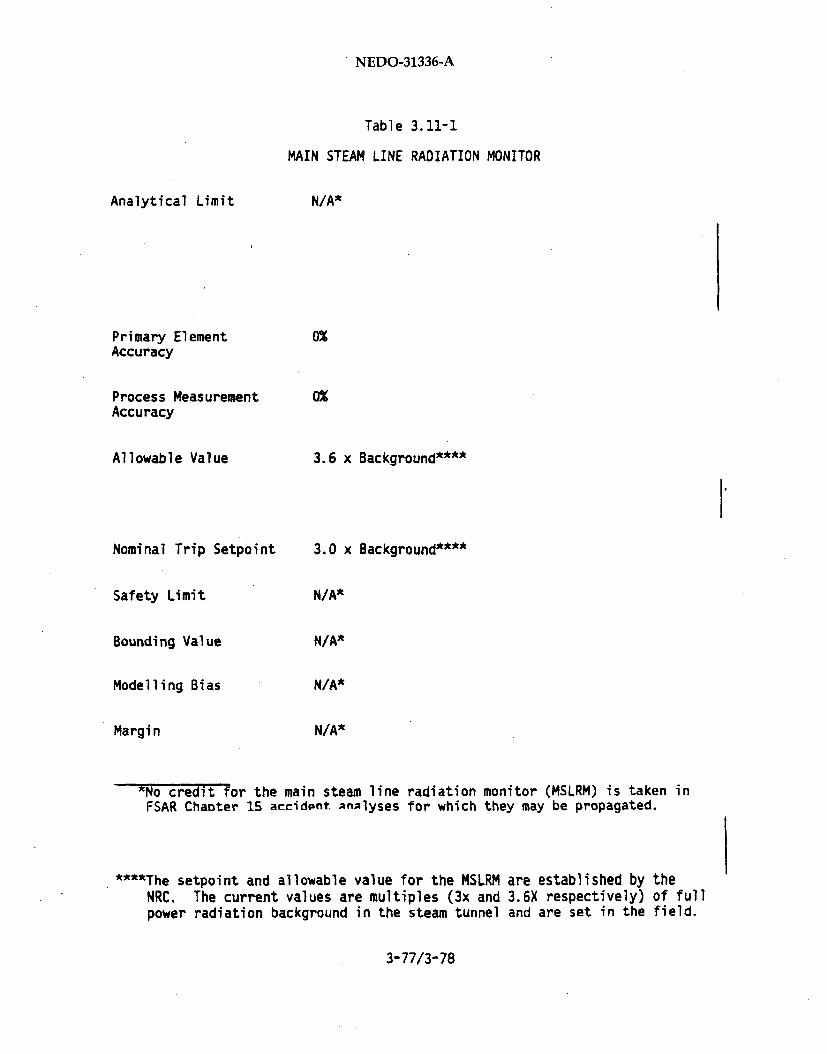
NEDO-31336-A
Table 3.11-1
MAIN STEAM LINE RADIATION MONITOR
Analytical Limit
Primary ElementAccuracy
Process MeasurementAccuracy
Allowable Value
Nominal Trip Setpoint
Safety Limit
Bounding Value
Modelling Bias
Margin
N/A*
0%
0%
3.6 x Background****
3.0 x Background****
N/A*
N/A*
N/A*
N/A*
*No credit for the main steam lineFSAR Chaoter 15 accident analyses
radiation monitor (MSLRM) is taken infor which they may be propagated.
****The setpoint and allowable value for the MSLRM are established by theNRC. The current values are multiples (3x and 3.6X respectively) of fullpower radiation background in the steam tunnel and are set in the field.
3-77/3-78
NEDO-31336-A
3.12 MAIN STEAM LINE LOW PRESSURE
3.12.1 Purpose
Main Steam Isolation Valve (MSIV) closure on low steam line pressure is
provided to protect the reactor system against uncontrolled
depressurization. Protection is provided primarily against a pressure
regulator malfunction which results in the turbine control and/or bypass
valves opening. The Main Steam Line (MSL) low pressure trip setpoint is
specified to limit the duration and severity of the depressurization so
that vessel thermal stresses (resulting from vessel cooldown rate) remain
below the appropriate safety limit and inventory loss is limited to prevent
uncovering fuel.
3.12.2 Trip Logic Description
Each of the four steam lines is furnished with pressure instrumentation to
measure steam line pressure upstream of the turbine stop valve. Logic is
provided to close the MSIVs when the reactor mode switch is in the "RUN"
position and the main steam line pressure drops below the specified
setpoint.
Pressure instrumentation for each of the four steam lines provides a signal
to a trip unit, one for each channel A,B,C and D. The trip unit signals,
in turn, feed into the logic circuit for closure of the MSIVs.
All plants except Clinton use relay logic for MSIV closure arranged in
one-out-of-two-twice logic, for input signals from channels A,B,C and D.
For this logic arrangement, all the MSIVs are tripped to close when either
channel A or C, and channel B or D provide low pressure trip signals. This
logic is bypassed when the reactor mode switch is not in "RUN" position to
permit startup of the plant.
3-79
NEDO-31336-A
The Clinton plant uses solid-state logic for MSIV closure arranged in
two-out-of-four logic. For this logic arrangement, all the MSIVs are
closed when two or more of the four channels provide low pressure trip
signals. This logic is bypassed when the mode switch is not in "RUN" mode
to permit startup of the plant.
3.12.3 Setpoint Calculations
The instrument setpoint calculations follow the methodology of Section 1.
Initial data include the Analytical. Limit (AL) and Operational Limit (OL)
specified on a historical basis, supplemented with transient performance
analysis. The AL is selected so that for the Design Basis Event (DBE)
corresponding to pressure regulator failure open event, vessel temperature
change rate is less than 100*F/hr (Reference 6) and reactor water level
does not drop below Level 1. The OL is selected so that MSL low pressure
trip is avoided during operational maneuvers and expected transients,
including turbine generator trips. The system engineer assigns values to
the instrument channel accuracy, calibration accuracy and drift, based on
knowledge of system requirements and instrumentation capabilities.
Instrument accuracy and drift are then confirmed using the methods in
Section 2. These values are used in calculating the Allowable Value (AV)
and the Nominal Trip Setpoint (NTSP), from the AL following the procedure
in Section 1. An example is presented in Table 3.12-1. The probabilities
of Licensee Event Report (LER) avoidance and spurious trip avoidance are
also calculated using the method described in Section 1.
3.12.4 Analysis
The DBE for MSL low pressure trip is the pressure regulator failure open
event. The REDY (NRC approved licensing evaluation model used in the FSAR
analysis) code was used to simulate this transient. The transient was
initiated from full power conditions of 105% Nuclear Boiler Rated (NBR)
steam flow for all plants except Fermi 2, which was initiated from 102% NBR
power. The analyses simulated a pressure regulator failure with 130% steam
3-80

NEDO-31336-A
Table 3.12-1
MAIN STEAM LOW PRESSURE
*Maximum normal primary system temperature change rate as allowed by the ASME.
3-81

NEDO-31336-A
flow as a worst case, compared with a 115% normal maximum limit. Sensor
and logic delays for trip functions were included in the simulation.
3.12.5 Assumptions and Uncertainties
The following assumptions are made in the setpoint determination:
(1)
(2)
(3)
(4),
(5)
(6)
3-82

NEDO-31336-A
3.13 MAIN STEAM LINE HIGH FLOW
3.13.1 Purpose
The flow in each of the four main steam lines is monitored by four differ-
ential pressure transmitters, which measure the pressure drop across a
venturi type flow element located between the reactor pressure vessel and
the inboard Main Steam Isolation Valves (MSIVs).
The flow element serves a dual purpose. It serves as the primary element
for the measurement of flow, and is also specifically designed to limit the
maximum flow in one steam line, resulting from a postulated guillotine
break of a main steam line, to a rate of flow 200% (170% for BWR/6) or less
of rated mass flow. This choked flow rate is the Design Safety Limit.
3.13.2 Trip Logic Description
Whenever the preset trip setpoint is exceeded, the flow transmitters and
their associated trip units cause the isolation logic to close the MSIVs in
all four main steam lines. There are a total of 16 high flow trip units,
one each for channels A, B, C and D for each of the four steam lines. For
relay logic plants (all plants except Clinton), the isolation logic for the
main steam lines is arranged in one-out-of-two twice logic. For Clinton,
the logic is two-out-of-four. Since high flow signals from any one steam
line will activate the isolation logic for all four steam lines, any one of
eight input signals from channels A and C, together with any one of eight
input signals from channels B and D, will close all eight isolation valves,
thus isolating all four main steam lines.
3.13.3 Setpoint Calculations
The instrument setpoint calculations follow the methodology described
Section 1. Plant-unique flow element calibration data are used to
convert 140% flow to differential pressure units (psid). This instrument
3-83

NEDO-31336-A
channel does not utilize square-root extraction, therefore all setpoint
calculations are done in psid'units.
The system engineer assigns values to the instrument channel accuracy,
calibration, and drift based on knowledge of system requirements and
instrumentation capabilities. The values for accuracy and drift are then
confirmed using the methods outlined in Section 2. In addition,
calculations are performed to determine the Process Measurement Accuracy
(PMA) and Primary Element Accuracy (PEA).
The Allowable Value (AV) and the Nominal Trip Setpoint (NTSP) are then
obtained by making allowances for instrument accuracy, calibration, drift,
PMA and PEA as appropriate. An example is presented in Table 3.13-1. The
probabilities of Licensee Event Report (LER) avoidance and spurious trip
avoidance are then calculated, using the methods described in Section 1.
Initial data includes the following:/
Analytical Limit: The Analytical Limit is specified at 140% of rated
mass flow, to provide a margin above the operational limit.
Operational Limit: The Operational Limit is specified at 127% of
rated flow based on operating experience, as a value that will avoid
isolation trips during any normal operating transients that cause
unbalanced flows in the main steam lines. Examples include closure of
one main steam line for valve testing and inadverdent opening of one.
bypass valve.
3.13.4 Analysis
In the analysis for the postulated guillotine break of a main steam line
outside the containment performed using the SAFE code (NRC approved
licensing evaluation model), it is assumed that the steam flow increases
instantaneously from a conservative full power steam flow of 105% of rated
3-84
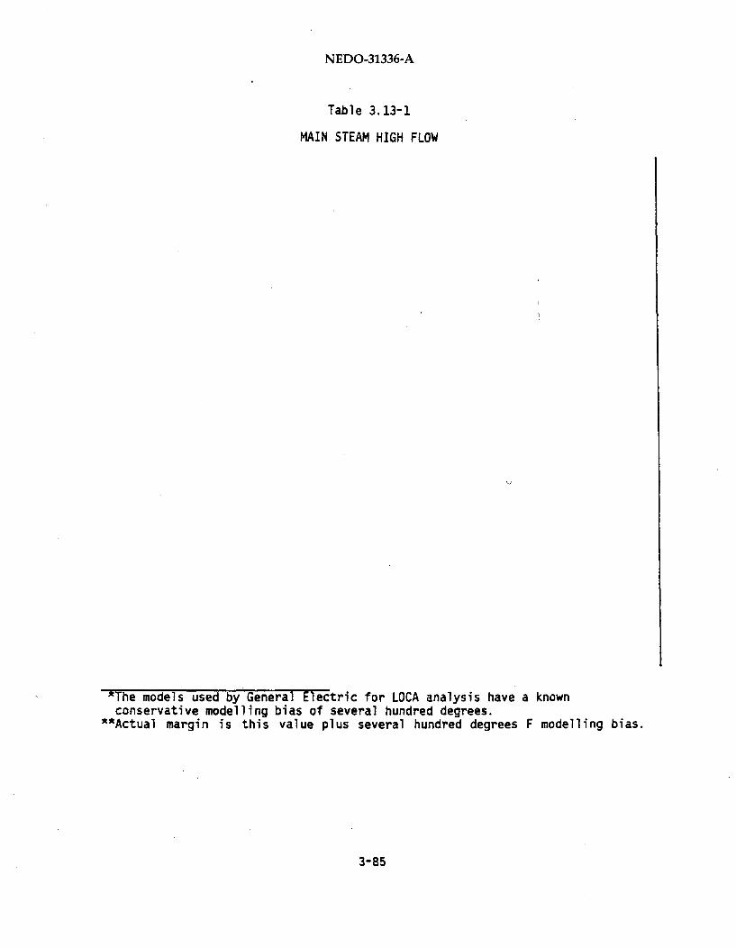
NEDO-31336-A
Table 3.13-1
MAIN STEAM HIGH FLOW
*The models used by General Electric for LOCA analysis have a knownconservative modelling bias of several hundred degrees.
"Actual margin is this value plus several hundred degrees F modelling bias.
3-85
NEDO-31336-A
to the Design Safety Limit (170% BWR/6 and 200% for BWR 4/5). The closure
signals are applied to the Main Steam Isolation Valves one half second
later.
The Design Safety Limit provides margin to ensure that the licensing safety
limits (postulated radiological consequences) are not exceeded. The
offsite radiological doses as a consequence of the event are limited to a
small fraction of 1OCFR100 limits.
3.13.5 Assumptions and Uncertainties
The following assumptions are used in the setpoint determination:
(1)
(2)
(3)
3-86

NEDO-31336-A
(4)
(5)
(6)
3-87/3-88

NEDO-31336-A
3.14 HIGH DRYWELL PRESSURE
3.14.1 Purpose
The drywell is the enclosure designed to withstand the expected peak
transient pressure that could result from the worst case postulated Loss of
Coolant Accident (LOCA) and is one of the barriers that prevents radioac-
tive release to the environment. During normal reactor operation, the
drywell in plants with Mark I or Mark II containments may have nitrogen
atmosphere, and the drywells in plants with Mark III designs contain air.
The drywell pressure is maintained close to atmospheric pressure when the
reactor is operating. An increase in the drywell pressure could indicate a
LOCA and the high drywell pressure trip is a signal used to identify such a
condition. The trip signal initiates reactor scram and contributes to
initiation of the Automatic Depressurization System (ADS) for all plants
except Perry and Nine Mile Point 2. High drywell also may initiate the
appropriate Emergency Core Cooling Systems (ECCS) such as High Pressure
Core Spray /High Pressure Coolant Injection, Core Spray /Low Pressure Core
Spray, and Low Pressure Coolant Injection function of the Residual Heat
Removal (RHR) system. High drywell pressure also provides a permissive for
containment spray initiation (for Perry, Clinton and Grand Gulf) and
contributes to isolation signals for all plants.
3.14.2 Trip Logic Description
Transmitters monitor pressure at four locations in the drywell, and are
located outside the drywell for Mark I and Mark II containments and connect
to the drywell atmosphere via instrument lines through drywell
penetrations.
On plants with Mark I or Mlark II containments, the transmitters are located
in the reactor building, while on plants with Mark III containments, they
are located inside the primary containment (but outside the drywell).
*Ine KtGu and = systems are on BWR/4 plants. BWR/5 and BWR/6 plants haveHPCS and LPCS, respectively, as the equivalent systems.
3-89
NEDO-31336-A
The logic necessary to initiate reactor scram requires two trip signals
designated as one-out-of-two-twice, except for Clinton which has
two-out-of-four logic. The ECCS systems have two or four instruments per
division which are combined with other transmitters (such as low water
level) that result in the systems initiation.
3.14.3 Setpoint Calculations
The instrument setpoint calculations follow the methodology in Section 1.
The system engineer assigns values to instrument channel accuracy,
calibration and drift based on knowledge of the system requirements and
instrumentation capabilities. The accuracy and drift are then confirmed
using the methods in Section 2. The Allowable Value (AV) and Nominal Trip
Setpoint (NTSP) are established per the methodology described by Section 1.
An example of a typical plant is presented in Table 3.14-1. The calcula-
tions for Licensee Event Report (LER) are also performed using the
methodology in Section 1.
Perry, Clinton and Grand Gulf use absolute pressure devices referenced to a
regional average barometric pressure. Additional consideration is given
for these plants to the margin available to minimize spurious trips under
expected high barometric pressure and assuring the analytical basis is not
violated when low barometric pressure is encountered.
3.14.4 Analysis
General Electric has historically used 2 psig as an analytical limit for
high drywell pressure trip (2.5 psig for Grand Gulf). This is conservative
and provides assurance that the bases for the accident analysis presented
in Chapter 6 of the FSAR are not violated. The bounding event is a small
break LOCA. The ECCS analysis assumes that high drywell pressure trip has
been received prior to reactor water Level 1 trip signal, such that theAuto Depressurization System (ADS) may be initiated. Drywell
pressurization calculations performed by GE show that for any break size
area above 2 square inches, the high drywell signal will occur before Level
1 is reached.
3-90

NEDO-31336-A
Table 3.14-1
HIGH DRYWELL PRESSURE
*The models used by General Electric for LOCA analysis have a known
conservative modelling bias of several hundred degrees."*Actual margin is the value plus several hundred degrees F modelling bias.
3-91
NEDO-31336-A
3.14.5 Assumptions and Uncertainties
The following assumptions are made in the setpoint determination:
(1)
(2)
(3)
(4)
(5)
(6)
3-92
NEDO-31336-A
3.15 HIGH CONTAINMENT PRESSURE
3.15.1 Purpose
The high containment pressure instruments provide a signal for initiation
of the containment spray mode of the Residual Heat Removal (RHR) System.
The RHR containment spray mode is required on some plants with I-ark III
containments to ensure condensation of steam which leaks into the
containment (wetwell) from inside the drywell without passing through the
suppression pool.
After a Loss of Coolant Accident (LOCA), the RHR system is devoted to the Low
Pressure Coolant Injection (LPCI) mode. Automatic switchover to the contain-
ment spray mode is inhibited by timers to allow for reactor water level
recovery. After an initial time period (approximately 10 minutes), if a high
containment pressure exists and a high drywell pressure signal also exists,
automatic transfer of the RHR System loops A and B from the LPCI mode to the
containment spray mode is initiated. Loop A transfer is initiated first,
Loop B transfer to the containment spray mode is delayed on some plants to
allow time for Loop A to reach rated containment spray. This reduces the
possibility that unnecessarily low containment pressures would occur due to
an over abundance of containment spray flow that may be associated with
simultaneous initiation of both loops. It has been demonstrated by
analysis that simultaneous initiation of both spray loops is acceptable
(for Clinton and Grand Gulf) and Grand Gulf has deleted the additional
1.5 minute time delay for Loop B initiation.
*This section of the report applies to the following plants only: Perry, GrandGulf, and Clinton.
3-93
NEDO-31336-A
3.15.2 Trip Logic Description
Four pressure transmitters are furnished to sense the containment (wetwell)pressure. Two transmitters are provided for RHR loop A and two for loop B.
The logic is arranged so that, if either one of the two Loop A containment
pressure instruments, as well as the drywell pressure instruments, is reading
above their setpoints after the timer has timed out, then RHR loop A will
transfer from the LPCI mode to the containment spray mode. After an
additional delay (on some plants), RHR loop B will also transfer to thecontainment spray mode when either one of the loop B containment pressureinstruments, as well as the drywell pressure instruments, is reading above
their setpoints. For Grand Gulf, both loops will transfer modes after the
timer has initially timed out (nominal of 10 minutes).
3.15.3 Setpoint Calculations
The instrument setpoint calculations follow the methodology described in
Section 1. The system engineer assigns values to the instrument channel
accuracy, calibration and drift selected based on knowledge of the systemrequirements and instrumentation capabilities. The instrument accuracy and
drift are then confirmed using the methods in Section 2. The methodology
presented in Section 1 is used to determine the Allowable Value (AV) andNominal Trip Setpoint (NTSP) based on the Analytical Limit (AL).
The probability of Licensee Event Report (LER) assistance is then calculated
using methods described in Section 1. Calculations for spurious trip
avoidances probability are not required for this device because there is nosignificant pressure increases in the containment during normal plant opera-
tion.
An example of the allowances made for the setpoint are presented inTable 3.15-1.
3-94

NEDO-31336-A
Table 3.15-1
HIGH CONTAINMENT PRESSURE
*Modelling bias and margin are inherent in the assumed bypass leakage (AV),which is significantly greater than the normally experienced in the field.The effects of conservative values of A/R, in terms of modelling bias andmargin have not been quantified.
3-95

NEDO-31336-A
3.15.4 Analysis
The Analytic Limit (AL) for the high containment pressure setpoint is estab-
lished such that the containment Mark III design pressure of 15 psig will not
be exceeded. Briefly, the AL is determined by the following procedure:
(1) Determine the equivalent drywell-to-wetwell bypass leakage area (A/I-)
which results in the containment reaching the design pressure of 15 psig
13 minutes after the postulated event. Thirteen minutes is the earliest
time assumed for spray availability based on 10 minutes for RHR dedica-
tion to LPCI plus 3 minutes delay till Loop B is able to achieve full
spray flow. Loop A is assumed to have failed.
(2) Calculate the containment pressure history for the assumed value of
bypass leakage.
(3) The AL used in determining the setpoint for spray initiation is taken to
be a pressure conservatively lower than the calculated containment
pressure 10 minutes after the postulated event. The AL has been estab-
lished by the type of analysis described above as 9 psig. The
containment pressure history typically shows that pressure is greater
than the AL at 10 minutes for the design basis event with maximum
allowable bypass leakage (conservatively greater than 9 psig).
The maximum allowable bypass leakage permitted by plant technical
specifications is an order of magnitude smaller than that. resulting from the
above conservative analysis procedure (using General Electric Computer
models). Actual measured bypass leakage is typically considerably less
than that permitted by plant technical specifications.
*Where A is area and K is the loss coefficient for the bypass leakage path(i.e., drywell to containment).
3-96
NEDO-31336-A
3.15.5 Assumptions and Uncertainties
The following assumptions are made in the setpoint determination:
(1)
(2)
(3)
(4)
(5)
(6)
3-97/3-98
NEDO-31336-A
3.16 LPCI/LPCS INJECTION VALVE INTERLOCKS
3.16.1 Purpose
The Low Pressure Core Injection (LPCI)/Low Pressure Core Spray (LPCS)
Injection Valves are motor operated stop valves which provide "go/no-go"
control for injection of coolant to the core from the low pressure Emer-
gency Core Coolant Systems (ECCS). The injection valves also serve as the
interface between the high pressure piping of the reactor vessel and the
lower pressure piping of the LPCI/LPCS systems. The LPCI/LPCS injection
valves open automatically for the Loss-of-Coolant Accident (LOCA)
condition. They are also actuated manually by remote manual switch from
the control room under operator procedural control for post-LOCA
adjustments of core cooling provisions, as well as for testing.
The interlocks which are the subject of this review inhibit the automatic
opening of the injection valves when the reactor vessel pressure is above
the maximum allowable design pressure of the LPCI/LPCS pump discharge
piping system (hereafter called Hi/Lo Pressure Interlock).
The Hi/Lo Pressure Interlocks have been incorporated to provide backup
assurance against low pressure coolant system piping failure from overpres-
sure. Protection against overpressure is provided in the basic system
design through a check valve which prevents backflow from the higher
pressure reactor vessel, and through relief valves in the lower pressure
piping sized in accordance with the requirements of the pertinent ASME
Code. The interlock provides protection for the event of a "single
failure" of the check valve in a non-closed position.
This description applies to BWR/4, 5 and 6 plants. For BWR/4 plants, theproper title is LPCI/Core Spray (CS); for simplicity of discussion, thedesignation LPCI/LPCS is used throughout this text when reference is toall plants.
3-99
NEDO-31336-A
3.16.2 Trip Logic Description
Figures 3.16-1 through 3.16-5 present schematic arrangements of interlock
logic for the different plants. These are further described below. For
clarity of discussion, although this review relates only to the automatic
function, the logic related to manual operation is included for all plants
both on the figures and in the descriptions.
Clinton (LPCI and LPCS)
Grand Gulf (LPCI and LPCS)
River Bend (LPCI and LPCS)
Separate interlocks inhibit valve operation for the accident condition andfor testing. Output signals of pressure switches, which sense reactor
steam dome pressure and which are arranged in one-out-of-two twice logic,
inhibit the valve from opening automatically from LOCA input signal or
manually from the Remote Manual Switch (RMS) when reactor vessel pressure
is above the low pressure system maximum allowable design pressure. Onelogic train provides output signals to both low pressure systems of an
electrical division; that is, one set of four transmitters and switchesprovides output for the injection valves of LPCS and LPCI (A), a second set
in the opposite electrical division supplies signals for LPCI (B) and
LPCI(C). The output signal from a separate pressure switch (the Clintondesign has two redundant switches), which senses pressure downstream of the
valve, provides a permissive for manual valve opening for testing when
downstream pressure is below the low pressure system maximum allowable
design pressure (See Figure 3.16-1).
3-100
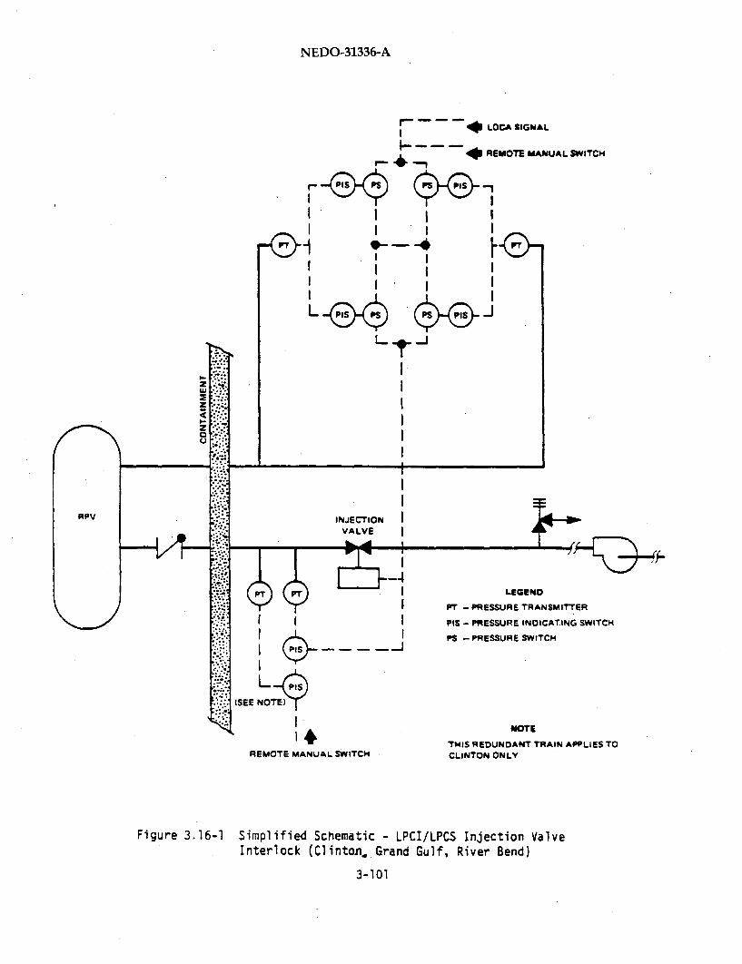
NEDO-31336-A
r-d& fLICA SIGNaAL
'-4
I.I I
40 REMOTE MANUAL SWITCH
I I9-- ---
.1
I II
I . I
I
(PT .-'- - ILEGEND
PT - PRESSURE TRANSMITTER
PIS - PRESSURE INDICATING SWITCH
PS -PRESSURE SWITCH
(SEE NOTEE)
I NOTE
1• TH.IS REDUNDANT TRAIN APPLIES TOREMOTE MANUAL SWITCH CLINTON ONLY
Figure 3.16-1 Simplified Schematic - LPCI/LPCS Injection ValveInterlock (Clinton. Grand Gulf, River Bend)
3-101

NEDO-31336-A
Perry (LPCI & LPCS)
Hope Creek (LPCI only)
The interlock inhibits automatic and manual valve operation. The output
signal from a pressure switch which senses pressure downstream of the valve
inhibits valve opening, from either automatic or manual signals, when
downstream pressure is above the low pressure system maximum allowable
design pressure (Figure 3.16-2).
Nine Mile Point 2 (LPCI & LPCS)
The interlock inhibits automatic and manual valve operation. The output
signal of a differential pressure switch, which senses the differential
between the reactor dome pressure and the pressure immediately upstream of
the valve, inhibits valve opening when this differential is above a value
consistent with the design pressure of the applicable low pressure coolant
system (Figure 3.16-3).
Limerick (LPCI only)
The interlock inhibits automatic and manual valve operation. The output
signal of a differential pressure switch which senses valve differential
pressure, inhibits valve opening when the differential pressure is above a
value consistent with the LPCI system maximum allowable design pressure
(Figure 3.16-4).
Hope Creek (Core Spray only)
Limerick (Core Spray only)
Fermi 2 (Core Spray and LPCI)
The interlock inhibits automatic and manual valve operation for the LOCA
condition. Output signals of pressure switches, arranged in one-out-of-two
twice logic, inhibit automatic valve opening from a LOCA input signal as
well as manual opening from the remote manual switch when reactor vessel
steam dome pressure is above that consistent with CSILPCI piping system
maximum allowable design pressure (Figure 3.16-5). A pressure interlock is
3-102

NEDO-31336-A
INJECTIONVALVE
IIII
- 0 LOCA
ILEGEND • !
P1" - PRESSURE TRANSMITTER IPIS - PRESSURE INDICATING SWTCH L.- ,4 REMOTE MANUAL SWITCH
Figure 3.16-2 Simplified Schematic - Injection Valve InterlockCLPCI/LPCS-Perry, LPCI-Hope Creek)
3-103

NEDO-31336-A
VESSEL
r . REMOTE MANUAL SIGNAL (RMS)
9- - - 41 LOCA SIGNAL
NUCLEAR BOILERSYSTEMINSTRUMENT LINE
CHECKVALVE
INJECTIONVALVE
RELIEFVALVE
PUMP
Figure 3.16-3 SIMPLIFIED SCHEMATIC- LPCI/LPCS INJECTIUN VALVEINTERLOCK (NINE MILE POINT 2)
3-104

NEDO-31336-A
INJECTIONVALVE
z
wz
cC)
. -4 REMOTE MANUAL SWITCH
40LOCA
Figure 3.16-4 SIMPLIFIED SCHEMATIC- LPCI INJECTION VALVE
INTERLOCK (LIMERICK)
3-105

NEDO-31336-A
r *LOCA
- - - * REMOTE MANUAL SWITCH,I
F_ I 41. -
-- REMOTEMANUAL
SWITCH
INJECTIONVALVE
Figure 3.16-5 SIMPLIFIED SCHEMATIC- INJECTION VALVE INTERLOCK
(LPCI/CS- FERM12, CS- HOPE CREEK, CS- LIMERICK)
3-106

NEDO-31336-A
not included in the logic for manual valve actuation for testing of these
systems. As shown in Figure 3.16-5, an additional valve is provided
upstream of the injection valve. The logic includes an interlock such that
the injection valve cannot be manually opened for test unless the normally
opened upstream valve is first closed.
3.16.3 Setpoint Calculations
The instrument setpoint calculations follow the methodology described in
Section 1. The procedure is to: (1) establish an upper pressure limit for
valve actuation from the allowable design pressure of the applicable low
pressure piping system; (2) from this upper limit and with selected design
characteristics for the instrumentation train to derive a nominal trip
setpoint for the interlock; and (3) for the selected instrumentation train
characteristics, to establish for automatic valve operation the lowest
potential reactor pressure to which valve actuation can be inhibited when
set at this established setpoint. This lowest potential reactor pressure
is then given as input for an analytical assessment of the adequacy of the
low pressure injection for core cooling when injection valve actuation is
inhibited by an interlock with this setpoint.
The Upper Analytical Limit (UAL) for the Hi/Lo Pressure Interlock is
derived through assessment of the allowable design pressures for piping and
components that comprise the pressure boundary between the drive pump and
the injection valve of the applicable low pressure coolant system. The UAL
is selected as the lowest of these allowable pressures after adjustment of
this pressure for water head between the elevation of the pipe/component
and the elevation at which the pressure is sensed. When applicable, this
lowest allowable pressure is converted to a differential pressure across
the valve with this same consideration of water heads.
Where deemed applicable, credit is taken for allowance of 110% of design
pressure per Subsection NB of ASME Section III on the basis that such
overpressure could be expected to have occurrence frequency well below the
one percent of plant life which is. permitted by the Code.
3-107
NEDO-31336-A
The system engineer assigns values to the instrument channel accuracy,
calibration, and drift based on knowledge of system requirements and
instrumentation capabilities. The accuracy and drift are then confirmed
using the methods in Section 2. In addition, process measurement accuracy
and primary element accuracy are determined as applicable. These values
are then used to determine an Upper Allowable Value (UAV) and a Nominal
Trip Setpoint (NTSP), corresponding to the Upper Analytical Limit. A Lower
Allowable Value (LAV), corresponding Nominal Trip Setpoint are then
determined from the Lower Analytical Limit (LAL). Any final NTSP lying
between the two nominal trip setpoints may then be utilized. The
determination of the last two values is performed only for automatic valve
actuation setpoints, not manual permissives.
The probability of Licensee Event Report (LER) avoidance is then calculated
using the methods described in Section 1. Spurious trip avoidance
calculations are not performed, since trip avoidance is not a concern, as
this is an interlock signal and not a trip. Further, the trip points are
on the order of 50% of the normal reactor operating pressure and,
therefore, spurious trip of the interlock during normal plant operation is
not a credible concern.
Setpoint examples from two different plants for LPCI and CS injection valve
interlocks are presented in Tables 3.16-1 and 3.16-2.
3.16.4 Analysis
ECCS performance is analyzed for the postulated guillotine break of the
reactor recirculation system primary piping to assess the maximum potential
adverse impact of adding the injection valve interlock. If this Design
Basis Accident (DBA) recirculation suction line break is not the limiting
break then a spectrum of large breaks must be analyzed. This is required
to determine whether the limiting break size changes as a result of the
injection valve interlock. In these analyses it is conservatively assumed
that flow through the injection valve is not initiated until the valve is
fully opened.
3-108

NEDO-31336-A
Analytical assessment of Peak Clad Temperature (PCT) for the LOCA condition
is performed with the with coolant injection inhibited until reactor
pressure is at the calculated LAL and the injection valve is fully open.
3.16.5 Assumptions and Uncertainties
The following assumptions are made in the setpoint determination:
(1)
(2)
(3)
(4)
3-109
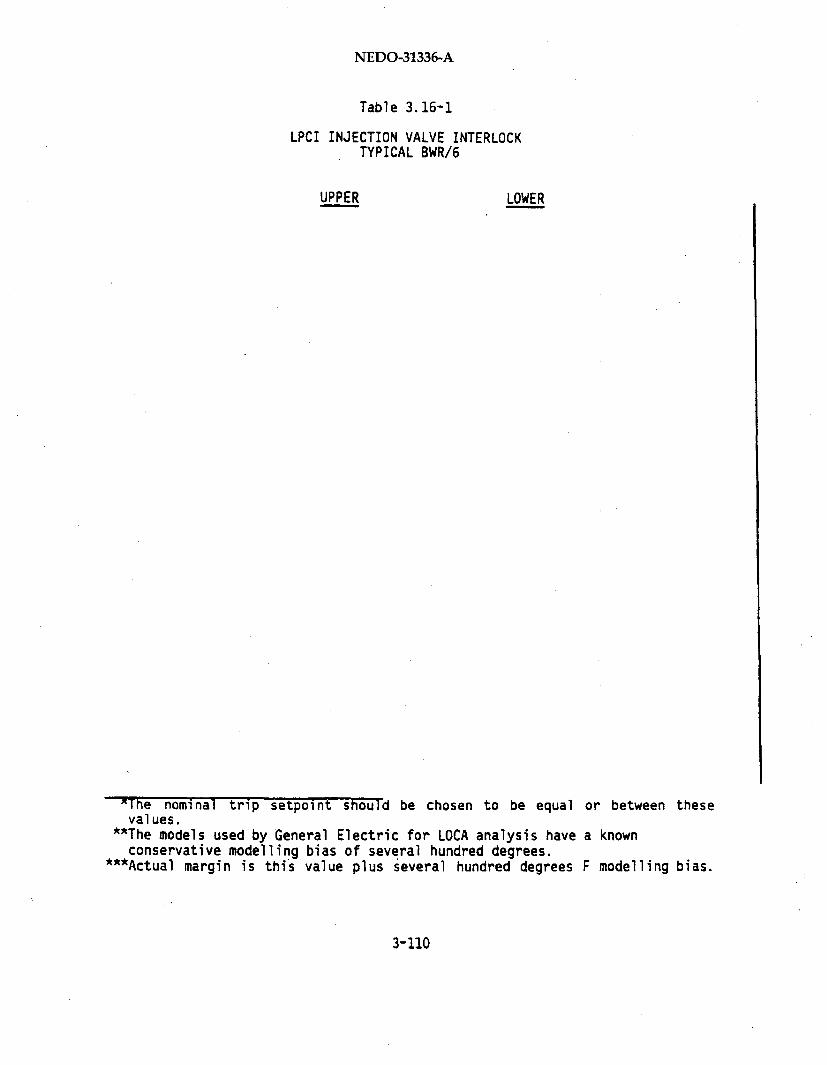
NEDO-31336-A
Table 3.16-1
LPCI INJECTION VALVE INTERLOCKTYPICAL BWR/6
UPPER LOWER
-The nominal trip setpoint should be chosen to be equal or between thesevalues.
*"The models used by General Electric for LOCA analysis have a knownconservative modelling bias of several hundred degrees.
*'*Actual margin is this value plus several hundred degrees F modelling bias.
3-110

NEDO-31336-A
Table 3.16-2
CS INJECTION VALVE INTERLOCKTYPICAL BWR/4 PLANT
UPPER LOWER
xReactor dome pressure."The nominal trip setpoint should be chosen to be equal or between these
values.**The models used by General Electric for LOCA analysis have a known
conservative modelling bias of several hundred degrees.****Actual margin is the value plus several hundred degrees F modelling bias.
3-111

NEDO-31336-A
(5)
(6)
3-112
NEDO-31336-A
3.17 LOW PRESSURE ECCS PUMP DISCHARGE PRESSURE HIGH
3.17.1 Purpose
The purpose of these instruments is to provide a signal to the Automatic
Depressurization System (ADS) control logic when the low pressure Emergency
Core Cooling System* (ECCS) pump(s) discharge pressure is high, as an
indication of pump operating status. These instruments have no direct
effect on the low pressure system control logic.
ADS action is required under conditions when reactor pressure is high and
reactor vessel water level is not being maintained by high pressure ECCS.
The ADS system is used to decrease reactor vessel pressure so that low
pressure systems can inject water to maintain vessel water level. Instru-
mentation on any single LPCI pump or a similar set of LPCS/CS instrumenta-
tion is required to provide the ADS initiation permissive in the ADS
initiation logic.
The pressure transmitter tap is connected to the low pressure ECCS pump
discharge piping downstream of the pumps and upstream of the discharge line
check valves. When there are two pumps per ECCS loop, each transmitter
monitors a similar point at the discharge of each pump.
This is true for either an automatic or a manual ADS initiation (Fermi 2
does not have manual initiation). Thus, if the emergency condition itself
did not result in automatic LPCS/CS or LPCI pump(s) starting, the plant
operator must start the pump(s) in at least one low pressure pump loop to
obtain the permissive condition for manual ADS initiation.
*BWR/5 and BWR/6-plants have Low Pressure Core Spray (LPCS) system whilethe BWR/4 plants have the Core Spray (CS) system. All plants have the LowPressure Coolant Injection (LPCI) mode of Residual Heat Removal (RHR).
3-113

NEDO-31336-A,
3.17.2 Trip Logic Description
Whenever ADS initiation is required, at least one LPCI or LPCS/CS pump loop
must be operating to allow the ADS initiation to proceed. ADS function can
be provided via either of two separate and redundant divisions (Fermi 2 has
both ADS redundant logic channels in one division). Each division of ADS
has two separate channels of logic. For one ADS division, each separate
channel must be satisfied because the final logic element prior to blowdown
is an "and" gate. Thus, the ADS low pressure pump permissive signals must
be two-out-of-two once to provide the proper permissive signal.
3.17.3 Setpoint Calculations
The instrument setpoint calculations follow the methodology described in
Section 1. The ADS pressure permissive setpoint must be (1) less than pump
discharge pressure when the pump is operating in the minimum flow bypass
mode and (2) high enough to avoid any condition which results in a
discharge pressure permissive when the LPCI and LPCS/CS pumps are aligned
for injection and the pumps are not running. These two criteria establish
the limiting conditions for the pressure setpoint Upper and Lower Safety
Limit (i.e., USL and LSL).
The upper safety limits corresponding to the first condition are 260 psig
for LPCI and 350 psig for LPCS/CS, while the lower safety limit
corresponding to the second condition are 55 psig for plants with Mark I
and II containments and 25 psig for plants with Mark III containments.
The system engineer assigns values to instrument channel accuracy, calibra-
tion, and drift based on a knowledge of system requirements and
instrumentation capabilities. The accuracy and drift are then confirmed
using the methods in Section 2.
3-114

NEDO-31336-A
Conservative values of 100 psig for LPCI and 110 psig for LPCS/CS are
selected as the Lower Analytical Limits (LAL). The Lower Allowable Value
(LAV) and Lower Nominal Trip Setpoint are established by adding allowances
for instrument accuracy, calibration and drift to the LAL.
The Upper Analytical Limit (UAL) is also conservatively chosen as 180 psig
for LPCS/CS and 150 psig for LPCI. The Upper Allowable Values (UAV) and
Upper Nominal Trip Setpoint are established by subtracting allowances forinstrument accuracy, calibration, and drift from the UAL. Licensee Event
Report avoidance is code confirmed for both the upper and lower nominal
trip setpoints. The nominal trip setpoint is then chosen to be between the
calculated upper and lower Nominal Trip Setpoints. This procedure assures
that an ADS permissive signal will be provided when the pumps are operating
and ready for injection. An example of a typical plants values are
included in Tables 3.17-1 and 3.17-2.
Calculations for spurious trip avoidances probability are not required for
this device because there is no significant pressure decrease in the
connected piping system during normal plant operation when the systems are
aligned for ECCS initiation.
3.17.4 Analysis
Safety analysis is not performed utilizing these setpoints.
3.17.5 Assumptions and Uncertainties
The following assumptions are made in the setpoint determination:
(1)
(2)
3-115

NEDO-31336-A
Table 3.17-1
LPCI PUMP ADS INTERLOCK
UPPER LOWER
3-116
NEDO-31336-A
Table 3.17-2
LPCS PUMP ADS INTERLOCK
UPPER LOWER
*The nominal trip setpoint should be chosen to be equal to or between thesevalues.
"*The models used by General Electric for LOCA analysis have a knownconservative modelling bias of several hundred degrees.
*'*Actual margin is this value plus several hundred degrees F modelling bias.
3-117

NEDO-31336-A
(3)
(4)
(5)
3-118
NEDO-31336-A
3.18 CONDENSATE STORAGE TANK LEVEL LOW1
3.18.1 Purpose
The purpose of the Condensate Storage Tank (CST) level low setpoint is to
initiate the automatic transfer of the systems whose pump suction source is
the CST source to the suppression pool source when water level in the tank
falls below a preset level. The following systems are involved: Reactor
Core Injection Coolant (RCIC) and High Pressure Coolant Injection (HPCI),
or High Pressure Core Spray*(HPCS). This setpoint also initiates an alarm
in the control room to alert the operator that the CST water inventory is
depleted.
This function is required to prevent loss of suction to the RCIC/HPCI/HPCS
pumps due to loss of water in the condensate storage tank. Loss of water
can occur as a result of large drawdown of the reserve volume or rupture of
the non-seismic tank or piping. Automatic switchover to the suppression
pool provides an assured suction source and allows for continued operation
of the pumps.
A condition of low condensate storage tank level can be received at any
time, causing the suppression pool suction valves to open. The setpoint
level is established at a minimum level which assures adequate Net Positive
Suction Head (NPSH) for pump operation during the transfer process.
3.18.2 Trip Logic Description
When the sensed CST water level falls below the preset trip setpoint, a
signal is generated which causes the system logic to automatically open the
appropriate systems' suppression pool suction valves. Upon reaching the
full-open position, a limit switch on the suppression pool suction valve(s)
is activated, which generates a signal causing closure of the suction
valves in the line from the CST. This completes the pump suction transfer
process.
*BWR/4 plants have HPCI systems while BWR/5 and 6 plants have HPCS systems.All plants have RCIC.
3-119

NEDO-31336-A
The instrumentation configuration consists of two completely redundant
channels contained within a single division. The signal is processed
within each channel by a transmitter and trip unit combination. For
HPCI/RCIC/HPCS, the suction transfer signal is generated by a
one-out-of-two logic (i.e., trip of either channel will signal the
suppression pool suction valves to open).
3.18.3 Setpoint Calculation
The instrument setpoint calculations follow the methodology described by
Section 1. The system engineer assigns values to instrument channel
accuracy, calibration and drift based on knowledge of system requirements
and instrumentation capabilities. The accuracy and drift are then
confirmed using the methods in Section 2. The probability of Licensee Event
Report (LER) avoidance is then calculated using the nethods described in
Section 1. Spurious trip avoidance calculations are not performed for this
setpoint because it is assumed that there is a large margin between normal
tank level and low level. An example of a typical plant are presented in
Table 3.18-1. Initial data includes the following:
Analytical limit: The analytical limit is determined as the tank
level which will provide sufficient NPSH during the suction transfer
to assure proper pump operation. Consideration is given to tank
geometry, suction line arrangement and in-line volumes, suppression
pool suction valve opening stroke time, and unusable tank volume.
3.18.4 Analysis
There is no safety analysis associated with condensate storage tank low
level setpoint.
3-120
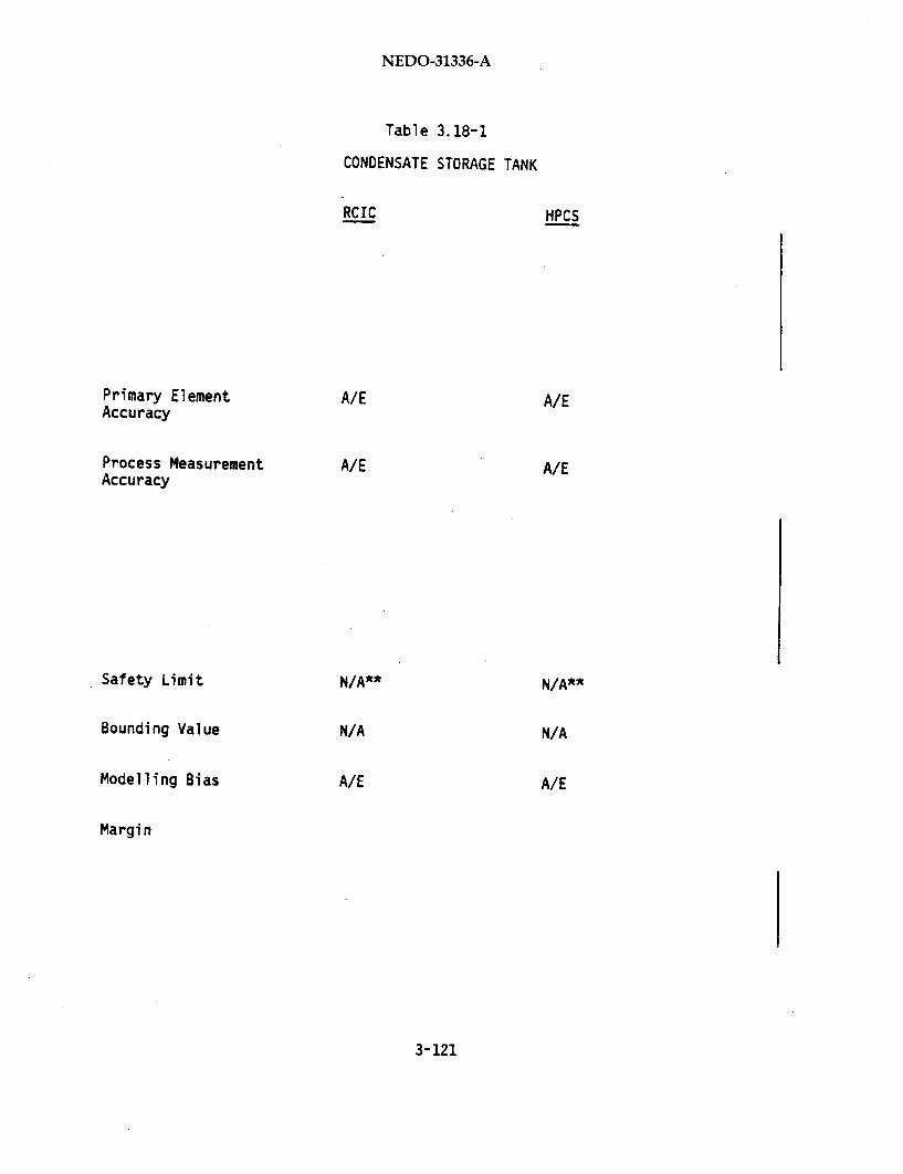
NEDO-31336-A
Table 3.18-1
CONDENSATE STORAGE TANK
RCIC HPCS
Primary Element A/E A/EAccuracy
Process Measurement A/E A/EAccuracy
Safety Limit N/A** N/A**
Bounding Value N/A N/A
Modelling Bias A/E A/E
Margin
3-121
NEDO-31336-A
3.18.5 Assumptions and Uncertainties
The following assumptions are made in the setpoint determination:
(1) Primary Element kcuracy: Primary element accuracy is dependent upon
the method the Architect/Engineer WA/E) uses to measure the method of
CST level.
(2) Process Mleasurement Accuracy: This is dependent upon the method of
measurement the Architect/Engineer (A/E) uses.
(3)
(4)
(5) Modelling Uncertainty: This is dependent upon the model the A/E uses.
(6)
3- 122"
NEDO-31336-A
3.18.6 Additional Information
The information contained in documents provided by GE is concerned only
with the instrument and instrument loop capabilities. The minimum conden-
sate tank level required to provide adequate pump suction flow is based on
the design of the tank and suction piping system. The A/E is responsible
for consideration of the effects of process measurement accuracy, response
time and modelling uncertainties on the minimum tank level required to
permit safe suction transfer.
3-123/3-124
NEDO-31336-A
3.19 ROD BLOCK MONITOR UPSCALE TRIP - BWR 4/5"
3.19.1 Purpose
The Rod Block Monitor (RBM), which is operable above 30% power, provides a
signal to permit operator evaluation of the changes in the local relative
power level during control rod movement. The RBM is designed to mitigate aRod Withdrawal Error (RWE) transient by blocking further control rod
withdrawal. This blocking action occurs when the RBI-I signal reaches a
predetermined level. RWE analyses are performed for each reload cycle at
the 100% power/1O0% flow (rated) operating condition. The required RBM rod
blocking setpoint is determined such that, starting from the operating
limit Minimum Critical Power Ratio (MCPR), the safety limit MCPR is not
violated. Experience has established that the MCPR determined trip
setpoints will assure that the fuel cladding 1% plastic strain threshold
(safety limit) is not exceeded. The setpoint is also supported by twolower trip level setpoints. Credit for the presence of these lower level
setpoints is taken for certain off-rated operating conditions.
3.19.2 Trip Logic Description
The RBM channel consists of Local Power Range Monitor (LPRM) detectors in
the core, cables from the detectors to the control room panels, LPRM/RBM
signal conditioning equipment, flow units and trip units in the control
room.
LPRM detectors are miniature fission chambers operating in the saturated
ion chamber region. These detectors provide ionization currents pro-
portional to the local neutron flux. The current signals of the detectors
surrounding a selected control rod (4 to 8 detectors depending on theposition of the control rod in the core) are then routed through cables to
* This report is applicable to N4ine Mile Point 2, Fermi 2, Limerick, andHope Creek. BWR/6 plants are not included because they do not have the RodBlock Monitor system; for these plants the Rod Withdrawal Limiter in theRod Control System performs a similar safety-related functions.
3-125

NEDO-31336-A
the LPRM signal conditioning equipment. This signal is then passed to the
RBM signal conditioning equipment which averages the LPRM4 inputs. If this
average value is not greater than the associated Average Power Range
Monitor (APPO) channel signal level, the RBM signal will be automatically
amplified to equal that of the APRM by stepping up the RBM gain. This gain
will be held until a new rod is selected. Three recirculation flow biased
trip levels, which are 8% apart, limit the local power change by allowing
the local average neutron flux indications to increase by a controlled
amount. A rod block signal will be sent to the Reactor aInual Control
System (RMCS) if this change is too large.
3.19.3 Setpoint Calculations
The instrument setpoint calculations used to determine the Nominal Trip
Setpoint (NTSP) and the Allowable Value (AV) for rod block monitor up-
scale trip follow the methodology described below.
In this study, the Analytical Limit (AL) is confirmed by statistically
combining all uncertainty values of this instrument loop and adding these
to the Nominal Trip Setpoint (NTSP). The uncertainties include conserva-
tive assumptions, such as assuming that the most responsive RBM channel is
bypassed and half of the LPRMs in the remaining RBM channel are failed.
However, this study also takes credit for the conservative effect of the
RBM signal noise relative to this trip setpoint.
All bias and variability values used in the uncertainty terms to confirm
the AL are evaluated and justified with the available manufacturer's or
field data. There are more details provided in Section 4.5.
3-126

NEDO-31336-A
(1)
3-127

NEDO-31336-A
(2)
3-128

NEDO-31336-A
(3)
(4)
3-129
NEDO-31336-A
Table 3.19-1 presents and example for a typical plant.
3.19.4 Analysis
The analytical limit for the rod block monitor upscale trip is determined
for each reload cycle by analyzing the Rod Withdrawal Error event. The
analysis considers both RBM channels to be operating and no LPRMs failed.
The analysis does not take credit for the presence of the setpoint clipping
capability of the backup rod block trip circuits, which will contribute
much less uncertainty than that from the flow unit and flow-biased trip
unit. The LPRM/RBM failure effects are then included as the uncertainties
of the RBM trip system in determining the setpoint margin.
3.19.5 Assumptions and Uncertainties
The following assumptions are made in the setpoint determination:
(a)
(b)
3-130

NEDO-31336-A
Table 3.19-1
ROD BLOCK MONITOR
*W is the measured recirculation drive flow.
3-131

NEDO-31336-A
(c)
(d)
(e)
(f)
3-132

NEDO-31336-A
3.20 HIGH APRM NEUTRON FLUX
3.20.1 Purpose
The reactor neutron flux is monitored with the Average Power Range Monitors
(APRM) of the Neutron Monitoring System (NMS). If neutron flux increases
to a preset high value, a trip signal to the Reactor Protection System
(RPS) will initiate reactor scram. Reactor scram is initiated to limit
maximum reactor power so as to maintain the peak vessel pressure below and
the Minimum Critical Power Ratio (MCPR) above the appropriate safety
limits.
3.20.2 Trip Logic Description
The RPS trip system consists of four logic channels. For relay plants (all
plants except Clinton), each RPS channel receives signals from two APRM
channels, averaging neutron flux signals from representative core wide
distributions of Local Power Range Monitors (LPRM). The trip logic for
scram is one-out-of-two twice (i.e., Channels A or C and Channels B or D
for BWR/6.and Channels A1 or A2 and B1 or B2 for BWR/4 and 5 plants).
For Clinton, the only plant utilizing solid-state logic, each RPS channel
receives a signal from one APRM channel, and scram logic is based on
two-out-of-four trip logic.
Each APRM channel (loop) consists of the LPRM detectors, cables from under
the vessel to the control room, LPRM/APRM signal conditioning equipment and
a trip unit (with a dc reference signal) in the control room or the
auxillary equipment room.
The LPRM detectors, are miniature fission chambers operated in the saturated
ion chamber region. They provide ionization currents proportional to the
local neutron flux. These current signals are then routed through shielded
cables to the LPRM signal conditioning equipment. The APRM signal condi-
tioning equipment, in turn, averages the voltage signals from selected LPRM
.signal conditioning equipment. The APRM voltage output, which is propor-
tional to the average neutron flux in the core or the percent of rated
3'-133
NEDO-31336-A
thermal power, is compared with a dc reference setpoint in the APRM trip
units, and a trip signal is sent to the RPS logic circuit if the reference
setpoint is exceeded.
3.20.3 Setpoint Calculations
The instrument setpoint calculations follow the methodology described in
Section 1. Initial data include the Analytical Limit (AL) and Operational
Limit (OL) specified on the basis of transient performance analysis. The
AL is chosen such that none of the FSAR transient analyses result in
violation of the appropriate safety limits, while the OL is chosen suchthat there is adequate operating margin to provide a reasonable range for
maneuvering while avoiding spurious scrams. The Analytical Limit is deter-
mined from the events outlined in Table 3.20-1 and the Operational Limit is
determined from a turbine load demand step.
The Allowable Value (AV) and the Nominal Trip Setpoint (NTSP). are estab-
lished following the procedure in Section 1 to account for instrument
channel accuracy, calibration, and drift. The procedure for APRM setpoint
validation calculations is presented in Section 4.5.
3.20.4 Analysis
The Design Basis Events (DBE) for the high APRM neutron flux scram setpoint
are summarized in Table 3.20-1. Both the peak vessel pressure and the
Minimum Critical Power Ratio (MCPR) safety limits are considered. For the
peak vessel pressure safety limit, the DBE is Main Steam Isolation Valve
(MSIV) closure with neutron flux scram. This is a conservative analysis
which assumes that the normal scram path associated with MSIV position
switches has failed. For the MCPR safety limit, the DBE is the FastRecirculation Flow Increase (FRFI) event (one loop) except for Grand Gulfand Limerick. For Grand Gulf, the appropriate DBE is Pressure/Turbine
Control System Failure, PTCSF (turbine control valves close at 200%/sec and
bypass valves open), because of its unique turbine control system design.
For Limerick, the appropriate DBE is Loss of Feedwater Heating (LFWH) in
3-134
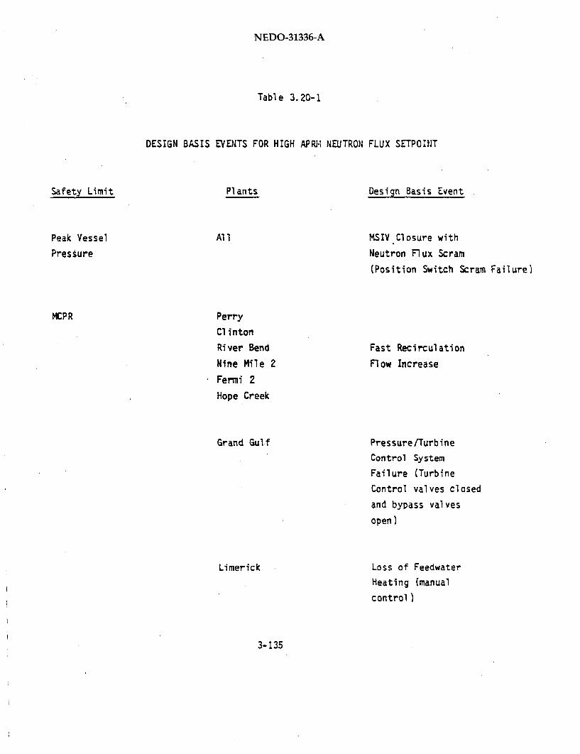
NEDO-31336-A
Table 3.20-1
DESIGN BASIS EVENTS FOR HIGH APRIi NEUTRON FLUX SETPOINT
Safety Limit PI ants
Peak Vessel
Pressure
Al I
MCPR Perry
Clinton
River Bend
Nine Mile 2
Fermi 2
Hope Creek
Design Basis Event
MSIV Closure with
Neutron Flux Scram
(Position Switch Scram Failure)
Fast Recirculation
Flow Increase
Pressure/Turbine
Control System
Failure (Turbine
Control valves closed
and bypass valves
open)
Loss of Feedwater
Heating (manual
control)
Grand Gulf
Limerick
3-135

NEDO-31336-A
the manual control mode because there is no Simulated Thermal Power Monitor
with a corresponding scram setpoint, and the point model analysis in the
Limerick FSAR conservatively shows the event reaching the high APRM flux
scram setpoint.
The MSIV closure and PTCSF events are analyzed with the REDY computer code
for Clinton and ODYN code for the other plants. The LFWH and FRFI events
are analyzed with REDY. REDY and ODYN are NRC approved licensing
evaluation models used in the FSAR analysis. The applicability of the
River Bend FSAR results to Clinton for pressurization transients is
justified in the Clinton FSAR (FSAR Section 15.2). Therefore, the MSIV
closure results are applied to Clinton. The MSIV closure, PTCSF and LFWH
events are initiated from full power conditions of 105% Nuclear Boiler
Rated (NBR) steam flow for all plants except Fermi 2, which was initiated
from 102% NBR power. The FRFI event is initiated from the minimum recircu-
lation pump speed limit condition for BWR/4 plants and from the minimum
recirculation valve position but maximum pump speed for the BWR/5 and BWR/6
plants. A scram delay (sensor plus logic) time of 0.09 sec is also simu-
lated.
The improved SCAT and ISCOR codes (NRC approved licensing evaluation models
used in FSAR analysis) are used to determine the MCPR limit and demonstrate
adequate margin to the Safety Limit MCPR.
The results of the analysis are summarized in Table 3.20-2 for a typical
plant.
3.20.5 Assumptions and Uncertainties
The following assumptions are made in the setpoint determination:
(1)
(2)
3-136
NEDO-31336-A
Table 3.20-2
HIGH APRM NEUTRON FLUX
*The reactor vessel bottom pressure corresponding to ASME moderate frequencyevent limits.
3-137

NEDO-31336-A
(3)
(4)
(5)
(6)
3-138
NEDO-31336-A
3.21 HIGH SIMULATED THERMAL POWER TRIP
3.21.1 Purpose
The Simulated Thermal Power (STP) trip signal is part of the Neutron
Monitoring System (NMS). The trip signal is used by the Reactor Protection
System (RPS) to scram the reactor to limit maximum reactor power so as to
maintain the Minimum Critical Power Ratio (MCPR) above the appropriate
safety limit for events such as Loss of Feedwater Heating. The STP set-
point is flow biased so that the scram setpoint is varied with the total
recirculation flow rate. The STP signal is derived by processing the
Average Power Range Monitor (APRM) neutron flux signal through a filtering
network with a time constant which is representative of reactor fuel
thermal dynamics. This signal closely approximates the average thermal
power during transient and steady-state conditions and thereby makes the
Neutron Monitoring System less susceptible to flux spikes under the fixed
neutron flux limit (typical allowable value of 120%). The STP trip is
designed to make operating BWR plants less susceptible to scrams caused by
spurious momentary neutron flux spikes.
3.21.2 Trip Logic Description
The Neutron Monitoring System consists of two major subsystems: (1) APRM
and (2) Recirculating Flow Monitoring.
The APRM subsystem consists of four channels, each receiving inputs from
incore Local Power Range Monitors (LPRMs). Each APRM channel averages
(electrically) the inputs from its assigned LPRMs and provides an output
signal proportional to the average of the LPRM flux signals.
The LPRM assignments to APRM channels ensure that each APRM channel
receives local neutron flux signals from all four axial locations in the
*Not applicable to Limerick.
3-139

NEDO-31336-A
core and from LPRMs in a representative radial distribution. Each APRM
channel will produce a signal proportional to the average neutron flux of
the whole reactor core.
The APRM signal is processed through a thermal power simulator circuit,
incorporating a typical time constant of six seconds, to produce an STP
signal.
The Recirculating Flow Monitoring subsystem provides APRM system trip units
with a signal proportional to total recirculation driving flow. Total
recirculation flow consists of the sum of the reactor recirculation pump
flow in both recirculation loops). The trip circuits which cause scram
trips to the RPS receive the total recirculation flow signal to "bias" or
vary the scram setpoint based on total recirculation flow.
The RPS consists of four logic channels. For relay plants (all plants
except Clinton), each RPS channel receives two APRM! channels. The RPS
incorporates a dual trip system design in which both trip systems must be
tripped in order to initiate a reactor scram. Each trip system utilizes
two redundant trip channels and a trip condition in either channel results
in a trip of that trip system. The logic arrangement is designated
one-out-of-two- twice logic. A trip condition in either channel A or C
coincident with a trip condition in either channels B or D results in
reactor scram for BWR/6 plants and for BWR/4 and 5 plants the proper
designation is A1 or A2 and B1 or B2 .
For Clinton, the only plant utilizing solid-state RPS logic, each RPS
channel receives one APRM channel and scram logic is based on two-out-of-four
trip logic.
3.21.3 Setpoint Calculations
The instrument nominal setpoint calculations follow the methodology of
Section 1. Initial data include the Analytical Limit (AL) and Operational
Limit (OL) specified on the basis of transient performance analyses. The
AL and OL, respectively, are chosen such that none of the FSAR transients
3-140

NEDO-31336-A
result in violation of the appropriate safety limits and there is adequate operating
margin to provide a reasonable range for maneuvering while avoiding spurious
scrams.
The Allowable Value (AV) and the Nominal Trip Setpoint (NTSP) are established
following the procedure in Section 1 to account for instrument channel accuracy,
accuracy and drift. The procedure for APRM setpoint validation calculations is
presented in Section 4.5.
3.21.4 Analysis
The Design Basis Event (DBE) for the high STP scram setpoint is Loss of
Feedwater Heating (LFWH) in the manual recirculation flow control mode.
The REDY computer code (NRC licensing evaluation model used in the FSAR
analysis) was used to simulate this transient. The transients were initia-
ted from full power conditions of 105% NBR steam flow for all plants except
Fermi 2, which was initiated from 102% NBR power. The transients are
simulated by programming a change in feedwater enthalpy corresponding to a
100°F loss in feedwater temperature. A scram delay (sensor plus logic)
time of 0.09 sec was included in the analyses.
The improved SCAT and ISCOR codes (NRC approved licensing evaluation models
used in FSAR analysis) were used to determine the MCPR limit and
demonstrate adequate margin to the safety limit MCPR.
Results of the analyses are summarized in Table 3.21-1 for a typical plant.
3.21.5 Assumptions and Uncertainties
The following assumptions are used in the determination of the setpoints:
(1) [
3-141

NEDO-31336-A
Table 3.21-1
HIGH SIMULATED THERMAL POWER
3-142

NEDO-31336-A
(2)
(3)
(4)
(5)
(6)
3-143/3-144
NEDO-31336-A
3.22 LOW CONDENSER VACUUM
3.22.1 Purpose
The purpose of the low condenser vacuum trip of the Main Steam Isolation
Valves (MSIVs) is to prevent an overpressure condition in the condenser
that could lead to rupture of the diaphragm installed to protect the
turbine exhaust hood. The initial reduction in vacuum results in a trip of
the main turbine (and if applicable, the feedwater turbine), which in turn
causes a reactor scram. Further reduction in condenser vacuum to the MSIV
closure trip setpoint results in closure of the turbine bypass valves and
the MSIVs.
3.22.2 Trip Logic Description
Four pressure transmitters are furnished on the main turbine condenser.
Logic is provided to close the MSIVs when the condenser vacuum drops below
the specified setpoint. Each transmitter provides a signal to a trip unit,
one for each Channel A, B, C and D.
All plants except Clinton use relay logic for MSIV closure arranged in
one-out-of-two-twice logic, for input signals from channels A, B, C and D.
For this logic arrangement, all the MSIVs are tripped to close when either
or both of Channels A and C, and either or both Channels B and D, provide
low vacuum signals at or below the MSIV trip setpoint. The Clinton plant
uses solid-state logic for MSIV closure arranged in two-out-of-four logic.-
For this logic arrangement, all the MSIVs are closed when two or more of
the four channels provide low vacuum trip signals.
The MSIV closure logic can be bypassed for plant startup by means of a
keylock bypass switch. The Limerick, BWR/5 and 6 plants also require the
.reactor mode switch to be in the Shutdown, Refueling, or Hot Standby
position for the bypass logic to take effect.
3-145

NEDO-31336-A
3.22.3 Setpoint Calculations
The instrument setpoint calculations follow the methodology of Section 1.
Upper and Lower Analytical Limits (AL) are both considered for the MSIV
trip function. The upper analytical limit (high vacuum), considered here,
limits the reactor vessel pressure transient caused by the closure of the
MSIVs to a reasonable level below the appropriate safety limit. The lower
analytical limit (low vacuum) protects the condenser against overpressure
(insure integrity of turbine exhaust hood diaphragm). The AL is selected
on a historical basis so that the minimum difference between the turbine
trip and isolation (closure of MSIVs and turbine bypass valves) low vacuumsetpoints is at least 10 in. Hg vacuum, including allowances for instrument
uncertainties and drift.
The system engineer assigns values to the instrument channel accuracy,
calibration accuracy and drift, based on knowledge of system requirements
and instrumentation capabilities. The values for instrument accuracy anddrift are then confirmed using the methods outlined in Section 2. These
values are used in calculating the Allowable Value (AV) and the NominalTrip Setpoint, from the AL following the procedure described in Section 1.
The setpoint calculations are also performed to assure sufficient margin
that the Lower Analytical Limit is not exceeded.
The probabilities of Licensee Event Report (LER) avoidance is then
calculated using the methods described in Section 1. Calculations of
spurious trip avoidance are not performed because of the large marginbetween normal condenser vacuum and the MSIV closure setpoint.
3.22.4 Analysis
The Design Basis Event (DBE) for low condenser vacuum MSIV trip is the loss
of condenser vacuum event. The REDY and ODYN codes (NRC approved licensing
evaluation models used in the FSAR analysis) are used to simulate thistransient. The transients are initiated from full power conditions of 105%
Nuclear Boiler Rated (NBR) steam flow for all plants except Fermi 2, which
is initiated from 102% NBR power. The analyses conservatively simulates a
3-146

NEDO-31336-A
10 inch Hg/sec vacuum decay rate in the main turbine condenser for Grand
Gulf, and 2 inch Hg/sec for all other plants. Sensor and logic delays for
trip functions are included in the simulation. However, the vacuum differ-
ence between the turbine trip and the isolation trips is modeled to corre-
spond to a specified value of 10 inch Hg.
Because the protective actions are actuated at various levels of condenser
vacuum, the severity of the resulting transient is directly dependent upon
the rate at which the vacuum is lost. Typical loss of vacuum due to single
equipment failure (e.g., loss of cooling water pumps or steam jet ejector
problem) produces very slow rate of loss of vacuum (minutes, not seconds).
If corrective actions by the reactor operators are not successful,
simultaneous trips of the main and feedwater turbines (if applicable) will
occur, and, ultimately, complete isolation will occur due to closure of the
bypass valves (opened with the main turbine trip) and the MSIVs. A faster
rate of loss of the condenser vacuum, as simulated in the analysis, reduces
the anticipatory action of the scram and the overall effectiveness of the
bypass valves, since the system is isolated more quickly.
The low vacuum isolation has the effect of increasing the peak reactor
pressure because it shuts off the steam which had been flowing through the
turbine bypass valves. The resulting isolation, well after the reactor has
been scrammed, produces a mild pressure increase handled easily by the
safety relief valves.
The results of the analysis are summarized in Table 3.22-1 for a
representative BWR plant.
3-147
NEDO-31336-A
Table 3.22-1
CONDENSER VACUUM
'The reactor vessel bottom pressure corresponding to ASME moderate frequencyevent limits.
3-148
NEDO-31336-A
3.22.5 Assumptions and Uncertainties
The following assumptions are used in the setpoint determination:
(1)
(2)
(3)
(4)
(5)
(6)
3-149/3-150
NEDO-31336-A
3.23 TURBINE CONTROL VALVE FAST CLOSURE
3.23.1 Purpose
The purpose of the turbine control valve fast closure sensors is to provide
timely signals that are indicative of the imminent or actual start of fast
closure of the turbine control valves. The signals are used to initiate
reactor scram and to initiate the trip of the reactor recirculation pumps
(if applicable) for events such as generator load rejections which causefast closure of the turbine control valve.
Generator load rejections require closure of the turbine control valves in
order to prevent damage to the turbine that could result from excessive
turbine acceleration or turbine overspeed. Turbine protection devices
therefore initiate the fast closure of the turbine control valves upon
detection of a significant imbalance between the electrical power being
generated and the actual load on the generator. Also, for events where a
full turbine trip is required, turbine protection devices usually initiate
fast closure of not only the turbine control valves but also the turbine
stop valves.
Reactor protection is required in order to mitigate the consequences of the
ensuing reactor pressurization transient. The required timing is dependentupon the reactor power level at the time the turbine control valves are
fast closed, and upon the sizing and operability of the turbine steam
bypass system. At low reactor power, the reactor pressure transient is
usually small, as steam flow from the reactor is diverted to the turbine
bypass system when the turbine control valves are closed, and no reactor
shutdown or scram may be needed. If the turbine bypass capacity is
insufficient to handle the steam flow being generated by the reactor or if
a failure of the turbine bypass system occurs, the Reactor Protection
System (RPS) high reactor steam dome pressure scram function and/or the
high neutron flux scram function are sufficient and timely enough to
mitigate the transient and assure adequate margins to the fuel thermal
hydraulic limits and reactor coolant boundary pressure limits.
3-151

NEDO-31336-A
However, when turbine control valve fast closures occur at high reactor
power levels, the reactor pressurization transient is much more rapid, and
reactor scram must be initiated earlier in the event to maintain required
fuel and reactor coolant boundary safety margins. Reactor scram may also
be complemented by immediate trip of the reactor recirculation pumps in
order to achieve faster turn around of the reactor power excursion
resulting from the pressurization event.
Different turbine protection and control designs by the various turbine
vendors, and different designs by even the same vendor, have resulted in
several different sensing methods to generate the signal indicating that
fast closure of the turbine control valves has occurred or will occur. The
most common method is to use pressure switches which monitor control valve
trip system hydraulic oil pressure for the individual valves. Other methods
are to monitor electrical signals (Fermi 2) generated by the turbine
protection system itself, or to monitor the pressure of the control oil
from the control valve servos (Grand Gulf).
3.23.2 Trip Logic Description
Four pressure switches interface with the trip logic (except Fermi 2 and
Grand Gulf) to cause reactor scram and Recirculation Pump Trip (RPT) if RPT
is supplied. Each pressure switch monitors the trip system oil pressure of
one of the four turbine control valves and is assigned to one of four trip
channels that feed into both the reactor scram and RPT logic circuits.
For plants with relay logic (all except Clinton), the RPS incorporates a
dual trip system design in which both trip systems must be tripped in order
to initiate a reactor scram. Each trip system utilizes two redundant trip
channels, and a trip condition in either channel results in a trip of that
trip system. The logic arrangement is designated one-out-of-two-twice
logic. A trip condition in either channels A or C coincident with a trip
condition in either channels B or D results in reactor scram.
3-152

NEDO-31336-A
The RPT design as applicable for relay plants also uses two trip systems.
However, in this case, the trip of either RPT trip system will result in
trip of the recirculation pumps. Two of the four channels are associated
with each RPT trip system and trip of both channels of a trip system arý
required to trip that trip system. This logic arrangement is designateh as
redundant two-out-of-two logic.
For Clinton, the only plant utilizing solid state logic, the same two-out-
of-four trip logic arrangement is used to initiate both reactor scram ard
RPT.
3.23.3 Setpoint Calculations
Upon initiation of control valve fast closure by the turbine control system
(via energization of the fast acting, solenoid valve), the trip system oil
pressure holding the disc dump valve closed drops from the normal range of
1500-1600 psig to zero within 8 to 10 miliseconds. When control valves are
initially full open (i.e., maximum control oil pressure in the hydraulic
cylinder), the valves trip system oil pressure must decrease to less than
400 psig before the disc dump valve will open to cause the control valve to
start to fast close. For initial control valve positions less than full
open, the valves trip system oil pressure must decrease to even lower
values before the control valves can start to close. Since the actual
analytical limit is the time of start of control valve fast closure and
since the control valves can't start to close fast until the oil pressure
decreases to 400 psig, the equivalent "analytical limit" established for
the pressure switches is 400 psig, decreasing.
Pressure switches are chosen to monitor the trip system oil pressure of the
individual turbine control valves for all plants except Grand Gulf and
Fermi 2. The equivalent "analytical limit" established for these pressure
switches is 400 psig, decreasing. Using this value as a starting point,the instrument setpoint calculations follow the methodology described in
Section 1.
3-153
NEDO-31336-A
The system engineer assigns values to the channel instrument accuracy,
calibration and drift, based on knowledge of system requirements and
instrumentation capabilities. The Allowable Value (AV) and Nominal Trip
Setpoint (NTSP) are obtained from the Analytical Limit by making allowances
as described in Section 1. An example is presented in Table 3.23-1. The
probabilities of Licensee Event Report (LER) and spurious trip avoidance
are then calculated using the methods described in Section 1.
There are no setpoint calculations for Fermi 2, since the RPS receives only
digital signals (contact closures) representing the fast closure
instruction from, and generated by, the turbine protection system itself.
As mentioned previously, for Grand Gulf the signals representing turbine
control valve fast closure are obtained by monitoring the pressure of the
control oil from the control valve servos. However, these signals are
generated by, and provided to the RPS by AE supplied equipment. Therefore,
the methodology used to derive the setpoints is out of the GE scope of
responsibility, although the GE specified response time requirement must
still be met.
3.23.4 Analysis
The Design Basis Event (DBE) that establishes-the actual setpoint
requirement as a point in time relative to start of control valve fast
closure is the generator load rejection event. The event analysis
conservatively assumes coincident failure of the turbine bypass valves.
The event is considered in the FSAR to be categorized as an infrequent
incident but is conservatively evaluated against the acceptance criteria
for moderate frequency events (i.e., Minimum Critical Power Ratio limit of
1.06 and vessel bottom pressure limit of 1375 psig).
3-154
NEDO-31336-A
The DBE is analyzed with the REDY computer code for Clinton and ODYN (NRC
approved licensing evaluation model used in FSAR analysis) for the other
plants. The applicability of the River Bend ODYN results to Clinton for
pressurization transients is justified in the Clinton FSAR (Section 15.2).
Therefore, the River Bend DBE results are applied to Clinton. The
transients are initiated from full power conditions, i.e., 105% of NuclearBoiler Rated (NBR) steam flow for all projects except Fermi 2, which startsfrom 102% NBR power conditions. The closure characteristics of the turbine
control valves are assumed such that the valves operate in the full arc
mode and have a full stroke closure time, from fully open to fully closed,
of 0.15 sec (0.2 sec for Fermi 2). The resulting closure time from the
105% NBR steam flow condition is typically 70 milliseconds as the controlvalves operating in the full arc mode are not fully open at the 105% NBR
steam flow conditions.
The scram delays and RPT delays (if applicable) are also simulated in the
analyzed transients. These delay times simulate the sensor response and
the logic and actuating device operating times and are measured from the
start of turbine control valve fast closure motion. The setpoints of theprocess monitored (if applicable) and the equipment comprising the logic
and actual trip devices are chosen such that the timing requirements used
as the analytical bases are satisfied.
The improved SCAT and ISCOR codes (NRC approved licensing evaluation models
used in FSAR analysis) are used to determine the bounding value of MinimumCritical Power Ratio (MCPR) during the transient and to demonstrate
adequate margin to the MCPR safety limit.
The results of the analyses are summarized in Table 3.23-1 for a typical
plant.
3-155
NEDO-31336-A
Table 3.23-1
TURBINE CONTROL VALVE FAST CLOSURE
*The reactor vessel bottom pressure corresponding to ASME moderate frequencyevent limits.
3-156
NEDO-31336-A
3.23.5 Assumptions and Uncertainties
The following assumptions are made in the setpoint determination:
(1)
(2)
(3)
(4)
(5)
(6)
3-157/3-158

NEDO-31336-A
3.24 TURBINE STOP VALVE CLOSURE
3.24.1 Purpose
The purpose of the Turbine Stop Valve (TSV) position sensors is to provide
timely signals that are indicative of the closing action (not fully open
condition) of the turbine stop valves. The signals are used to initiate
reactor scram and to initiate the trip of the reactor recirculation pumps
(if applicable) for events which cause closure of the turbine stop valves.
Turbine trip events require closure of the turbine stop valves in order to
prevent damage to the turbine that could result from various abnormal
conditions. Turbine protection devices, therefore, initiate the closure of
the turbine stop valves upon detection of turbine overspeed, low condenser
vacuum, excessive vibration, reactor high water level (Level 8), and other
pertinent parameters.
Reactor protection is required in order to mitigate the consequences of the
ensuing reactor pressurization transient. The required timing of reactor
protection is dependent upon the reactor power level at the time the
turbine stop valves are closed, and upon the sizing and operability of the
turbine steam bypass system. At low reactor power, the reactor pressure
transient is usually small, since steam flow from the reactor is diverted
to the turbine bypass system when the turbine stop valves are closed, and
no reactor shutdown or scram may be needed. If the turbine bypass capacity
is insufficient to handle the steam flow being generated by the reactor or
if a failure of the turbine bypass system occurs, the Reactor Protection
System (RPS) high reactor steam dome pressure scram function and/or the
high neutron flux scram function are sufficient and timely enough to
mitigate the transient and assure adequate margins to the fuel thermal
hydraulic limits and reactor coolant boundary pressure limits.
3-159

NEDO-31336-A
However, when TSV closure occurs at high reactor power, the reactor pres-
surization transient is much more rapid, and reactor scram must be
initiated earlier in the event to maintain required fuel and reactor
coolant boundary safety margins. Reactor scram may also be complemented by
immediate trip of the reactor recirculation pumps in order to achieve
faster turnaround of the reactor power excursion resulting from the
pressurization event.
3.24.2 Trip Logic Description
For relay plants (all except Clinton), eight limit switches interface with
the trip logic used to cause reactor scram and Recirculation Pump Trip(RPT) if RPT is supplied. These switches, which indicate the open or
not-fully-open conditions of the stop valves, are arranged two per valve,
each of the switches being assigned to a different RPS trip channel. GrandGulf uses pressure switches which monitor the oil pressure instead of TSV
position switches.
For relay plants, the RPS incorporates a dual trip system design in which
both trip systems must be tripped in order to initiate a reactor scram.Each trip system utilizes two redundant trip channels, and a trip condition
in either channel results in a trip of that trip system. The logic
arrangement is designated one-out-of-two-twice logic.
The TSV closure trip logic for relay plants is arranged such that one or
two turbine stop valves can be in the not-fully-open positions (for test
purposes) without causing a reactor scram, provided the power has beenreduced sufficiently to limit reactor pressure and steam flow. A full RPS
trip (reactor scram) will result whenever three or more turbine stop valves
are in the not-fully-open positions (provided that the reactor power is
above the equivalent turbine first-stage pressure bypass for TSV closure
and turbine control valve fast closure trips).
The RPT design for relay plants (as applicable) also uses two trip systems.
However, in this case, the trip of either RPT system will result in trip of
the recirculation pumps. Two of the four RPS channels are associated with
3-160
NEDO-31336-A
each RPT system, and trips of both RPS channels associated with a RPT trip
system are required to trip that trip system. This logic arrangement is
designated as redundant two-out-of-two logic.
For Clinton, the only plant utilizing solid-state trip logic, only one
limit switch per stop valve is used, each being assigned to a unique RPS
division. The same two-out-of-four trip logic arrangement is used to
initiate both reactor scram and RPT. Thus, only two turbine stop'valves
need be in the not-fully-open positions in order to cause a reactor scram.
3.24.3 Setpoint Calculations
Historically, the Analytical Limit (AL) has been chosen to be the190% open
position. Analyses have been performed using the AL to demonstrate that
the FSAR transients which use the TSV closure trip setpoint do not violate
the appropriate safety limits.
The instrument setpoint calculations used to determine the Nominal Trip
Setpoint (NTSP) and the Allowable Valve (AV) for turbine stop valve closure
trip follow the methodology described in Section 1. The system engineer
assigns values to the instrument loop accuracy, calibration and drift based
on knowledge of the instrument capabilities and system requirements. These
values are then used in the setpoint determination. The Licensee Event
Report (LER) avoidance is also determined using methods in Secion 1.
3.24.4 Analysis
Two Design Basis Events (DBE) apply to the TSV closure trip. The feedwater
controller failure to maximum flow demand is the DBE for the Minimum
Critical Power Ratio (MCPR) safety limit, and the turbine trip event is the
DBE for the maximum reactor pressure safety limit. The turbine trip is
conservatively assumed to include failure of 50% of the turbine bypass
system capacity (13% NBR Steam Bypass Flow and 10% NBR Reheater FlIw) for
Fermi 2, and total failure of the bypass system capacity for the other
plants.
3-161
NEDO-31336-A
The turbine trip event with failure of the bypass system is considered by
GE to be categorized as an infrequent incident, but is conservatively
required by the NRC to be compared in the FSAR to the criteria for moderate
frequency events (i.e., MCPR safety limit of 1.06 and maximum vessel
pressure safety limit of 1375 psig).
These DBEs were analyzed with the REDY computer code for Clinton and the
ODYN code (NRC approved licensing evaluation models used for FSAR analysis)
for the other plants. The applicability of the River Bend FSAR ODYN
results to Clinton for pressurization transients is justified in the
Clinton FSAR (Section 15.2). Therefore, the River Bend turbine trip
results are applied to Clinton. The transients were simulated with
protective functions assumed to operate at appropriate analytical limits.
The transients were initiated from full design power conditions of 105%
Nuclear Boiler Rated (NBR) steam flow for all plants except Fermi 2, which
was initiated from 102% NBR power. For the analysis, conservative TSV
closure times, (typically 0.1 sec), were used. Appropriate delay times
(sensor plus logic) for the scram and for the RPT (if applicable) functions
were also simulated. The delay times are measured from the time the TSVs
reach the trip setpoint until initiation of the respective function.
The results of the analyses are sunmmarized in Table 3.24-1 for a typical
plant.
3.24.5 Assumptions and Uncertainties
The following assumptions were made in the setpoint determination:
(1)
(2)
(3)
3-162

NEDO-31336-A
Table 3.24-1
TURBINE STOP VALVE FAST CLOSURE
*The reactor vessel bottom pressure corresponding to ASME moderate frequencyevent limits.
3-163

NEDO-31336-A
(4)
(5)
(6)
3-164
NEDO-31336-A
3.25 TURBINE FIRST STAGE PRESSURE
3.25.1 Purpose
The turbine first stage pressure sensors are used for an indirect measure-
ment of reactor power. They provide an automatic bypass of the Turbine
Stop Valve Closure (TSVC) and Turbine Control Valve Fast Closure (TCVFC)
reactor scram and Recirculation Pump Trip (RPT) functions (if applicable)
at low reactor power levels where an immediate scram from closed or closing
turbine valves is not required. The trip bypass is in effect whenever
Turbine First Stage Pressure (TFSP) is below a specified value, and thus
permits continued reactor operation with the turbine stop valves and/or
turbine control valves closed. At the lower reactor power levels, the
reactor pressurization transients resulting from TSVC or TCVFC are usually
small, as steam flow from the reactor is diverted to the condenser via the
turbine steam bypass system when the turbine stop or control valves are
closed, and no reactor scram may be needed. In the event of inadequate
turbine bypass capacity or failure of the turbine bypass system, adequate
reactor protection is provided by the diverse high reactor dome pressure or
high neutron flux scram functions.
Safety requirements related to this trip bypass are that the TSVC and TCVFC
trip functions are enabled (i.e., bypass removed), at or before exceeding
30% of rated reactor power for Hope Creek, Limerick, Nine Mile Point 2; at
or before exceeding 36% of rated reactor power for Fermi 2; and at or
before exceeding 40% of rated reactor power for Clinton, Perry, River Bend
and Grand Gulf. The reactor power levels are design basis values chosen
primarily for the purpose of permitting the capability of continued low
power reactor operation with turbine stop and/or control valves closed and
with reactor steam flow diverted through the turbine bypass valves.
Turbine valve closure transients are evaluated in the Final Safety Analysis
Report and full power events are considered to be bounding.
3-165
NEDO-31336-A
Turbine first stage pressure has been historically used as the parameter to
approximate reactor power and effect the actual trip bypass. The Reactor
Protection System (RPS) design purposely chooses this parameter, as opposed
to the more direct measurement of power such as neutron flux, in order to
assure diversity between the TSVC and TCVFC scram functions and the neutron
flux scram function.
3.25.2 Trip Logic Description
Four pressure sensors are connected to the high pressure turbine via
instrument lines to monitor either turbine bowl pressure or turbine first
stage shell pressure. The choice is dependent upon characteristics of
turbine operation. The pressure being monitored varies essentially linear-
ly with turbine throttle flow over the full range of turbine operation.
All plants associated with this study utilize pressure transmitters and
trip units. The transmitters, located in the turbine building, are cali-
brated with a span range from 0 to 100% of the plant uniquevalue of
turbine first stage pressure that results at Valves Wide Open (VWO) turbine
throttle flow. Each of the four transmitter/trip unit sets is associated
with one of the four RPS logic channels. The TSVC and TCVFC trips for an
individual RPS channel are bypassed as long as the input from the pressure
transmitter is below the setpoint of the trip unit associated with that RPS
channel. The trip units are adjusted to remove the bypass condition (i.e.,
enable the TSVC and TCVFC trip functions) when increasing turbine first
stage pressure (i.e., increasing reactor power) passes the appropriate
setpoint.
The logic arrangements used to bypass the TSVC and TCVFC reactor scram and,when applicable, RPT functions are essentially the converse of the logic
used to cause the trips.
For plants with relay logic (all, except Clinton), where the RPS
incorporates a dual trip system design in which both trip systems must be
tripped in order to initiate a reactor scram, the trip bypass logic
3-166
NEDO-31336-A
arrangement must thus only prevent the trip of one of the two trip
systems in order to bypass the reactor scram at low reactor power levels.However, since each trip system has two redundant trip channels, both
channels of either of the two RPS trip systems must be in a bypassed statein order to bypass the TSVC and TCVFC trip functions. These trip functions
are thus bypassed if the turbine first stage pressure trip bypass tripunits of both channels A and C are in the bypassed state or if the trip
units of both channels B and D are in the bypassed state for Perry, River
Bend and Grand Gulf. For Hope Creek, Limerick, Fermi 2 and Nine Mile Point
2, the trip functions will be bypassed when A1 and A2 are in the bypassed
state or B1 and B2 are in the bypassed state. Such bypass logic
arrangement is designated two-out-of-two per trip system. Under normal
conditions of low power operation, all four transmitters would be
monitoring low turbine first stage pressure, and both trip systems would be
bypassed. The bypass resulting from a single turbine first stage pressure
trip unit affects only the TSVC and TCVFC trip functions of a single RPS
channel. No other trip functions (e.g., high neutron flux or high reactor
dome pressure) in that RPS channel are affected.
The turbine/generator trip RPT function, which is initiated on most plants
from TSVC or TCVFC at high reactor power levels, is also a dual trip system
design for the relay plants. However, in this case, the trip of either RPT
trip system results in trip of the recirculation pumps. Thus, for projectswhich have this trip function, both RPT trip systems must be bypassed to
bypass the trip of the recirculation pumps. For the majority of relay
projects, the trip bypass logic requires that all four trip units be in the
bypassed state to effect the low power bypass of the TSVC and TCVFC RPT
function.
Clinton (the only plant with solid state logic) utilizes two-out-of-four
channel trip logic to cause both reactor scram and RPT upon TSVC and TCVFC
from high power levels. The trip bypass logic arrangement used to bypass
these trip functions at low reactor power levels requires that at least
3-167

NEDO-31336-A
three of the four turbine first stage pressure trip bypass channels be in
the bypassed state to effect the bypass of both the scram and RPT trip
functions.
3.25.3 Setpoint Calculations
Prior to performing setpoint calculations, additional evaluations are
required to determine appropriate values of Turbine First Stage Pressure
(TFSP) that are conservatively equivalent to the Analytical Limit (AL) or
reactor power. A generic evaluation was used for BWR/6 plants (Grand Gulf,
Clinton, Perry, River Bend) to establish the values of TFSP that are
conservatively equivalent to 40% of rated reactor power. Unique
evaluations were used to establish the TFSP values that are conservatively
equivalent to 30% of rated reactor power for Limerick, Hope Creek, Nine
Mile Point 2 and 36% of rated reactor power for Fermi 2. These evaluations
consider the non-linear relationship of reactor vessel steam flow to
reactor power level and, also, conservatively account for the steam flow
used for reheaters, feedwater turbines, steam jet air injectors and valve
stem sealing purposes. The evaluation process thus involves determining
the minimum vessel steam flow corresponding to the applicable reactor power
level, subtracting a conservative estimate of the steam flow not passing
through the high pressure turbine and then ratioing this remaining steam
flow to the steam flow that exists at turbine VWO conditions. This result-
ing value is also the ratio of TFSP at the chosen reactor power level to
the TFSP at VWO conditions. By requiring that the transmitters' spans be
calibrated from 0 to 100% of the plant-unique values of TFSP at VWO condi-
tions, the resulting ratios (in terms of percent of VWO TFSP) are thus the
conservatively determined equivalents to the design basis values of rated
reactor power. These equivalent values are used as the starting points for
the calculations setpoints following the methodology described in Section1.
The system engineer assigns values to the instrument accuracy, calibration
and drift, based upon knowledge of system requirements and instrumentation
capabilities. The values assigned for instrument accuracy and drift are
then confirmed using the methods in Section 2. The Allowable Value (AV)
3-168

NEDO-31336-A
and Nominal Trip Setpoint (NTSP) are obtained from the AL by making allow-
ances as described in Section 1. The probability of Licensee Event Report
(LER) avoidance is also calculated using the methods described in Section1.
3.25.4 Analysis
The Design Basis Event (DBE) for TFSP bypass of TSVC and TCVFC trips is the
generator load rejection event with turbine bypass failure. This event is
categorized as an infrequent event, but is conservatively evaluated against
the acceptance criteria for moderate frequency events [i.e., Minimum
Critical Power Ratio (MCPR) safety limit of 1.06 and vessel bottom pressure
of 1375 psig].
The ODYN code (NRC approved licensing evaluation model used in FSAR analy-
sis) was used to simulate these DBEs for typical plants of each BWR class.
The transients were initiated from 30% of nuclear boiler rated (NBR) power
for Nine Mile Point 2, Limerick, and Hope Creek; 36% NBR for Fermi 2; and
40% NBR power for Clinton, Grand Gulf, Perry and River Bend. The closure
characteristics of the turbine control valves are assumed such that the
valves operate in the full arc mode and have a full stroke closure time,
from fully open to fully closed, of 0.15 second (0.2 sec for Fermi 2). No
credit was taken for the neutron flux scram since that signal may or may
not reach its trip setpoint. Scram, in this situation, is conservatively
initiated from the reactor dome high pressure analytical limit setpoint.
Appropriate delay times (sensor plus logic) are included in the analysis.
The improved SCAT and ISCOR codes (NRC approved licensing evaluation models
used in the FSAR analysis) were used to determine the bounding values of
MCPR during the transients and to demonstrate adequate margin to the MCPR
safety.
Results of the analyses are presented in Table 3.25-1 for a typical. plant.
3-169

NEDO-31336-A
Table 3.25-1
TURBINE FIRST-STAGE PRESSURE
*For this example scale of 0 to 100% of Valves Wide Open (VWO) corresponds toa scale of 0 to 701.5 psig turbine first-stage pressure.
**The reactor vessel bottom pressure corresponding to ASME moderate frequencyevent limits.
3-170
NEDO-31336-A
3.25.5 Assumptions and Uncertainties
The
(1)
(2)
(3)
(4)
(5)
(6)
3-171/3-172
NEDO-31336-A
4.0 NRC OPEN ITEMS
This section of the report contains the General Electric responses to the
NRC letter on Instrument Setpoint Methodology (letter to Mr. John Carolan
from the Nuclear Regulatory Commision subject "Instrument Setpoint
e'thodology for General Electric Supplied Protection System
Instrumentation" dated I.ay 15, 1984.) The reponses to the NRC letter are
organized according to the open item numbers assigned by the NRC in their
letter.
4-1/4-2
NEDO-31336-A
4.1 NRC OPEN ITEM 5. 1 - ENVIRONMIENTAL EFFECTS
This responds to Item 5.1 of the NRC Staff Report dated May 15, 1984 titled
"Transmittal of NRC Staff Report of Setpoint Methodology for General
Electric Supplied Protection System Instrumentation". The NRC staff
recommends that the effect of drywell temperatures on instrument sensing
lines should be considered, utilizing guidance and information from BWR
Owners' Group Reports.
4.1.1 Response
4-3

NEDO-31336-A
4-4
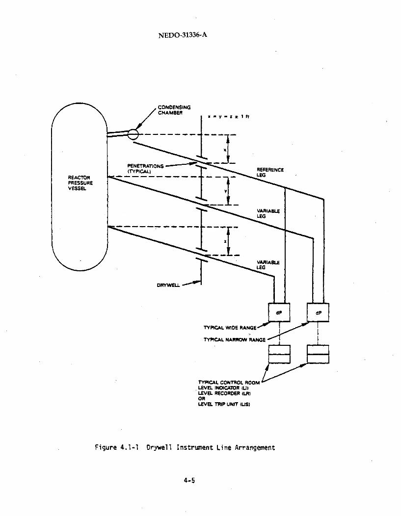
NEDO-31336-A
CONDENSINGCHAMBER
x-y-z*lft
REFERENCELEGREACTR
PRESSUREVESSEL
DRYWEILL
TYPICAL
TYPICAL
TYPICAL CONTROL ROOM'LEVEL INDICATOR (U)LEVEL RECORDER (LR)ORLEVEL TRIP UNIT (US)
Figure 4.1-1 Drywell Instrument Line Arrangement
4-5

NEDO-31336-A
4-6
NEDO-31336-A
The second portion of NRC Question 5.1 requested an evaluation of the
adequacy of the equations used for statistical summation of errorsapplicable for a normal environment versus the uncertainties associatedwith possibly dependent effects of off-normal or harsh conditions.
4-7

NEDO-31336-A
4.1.2 Error Analysis
4-8

NEDO-31336-A
4.2 NRC OPEN ITE4 5.2 - VALIDATION OF DESIGN ALLOWANCES
The validation of design allowances is presented in this report using a
typical plant. Specific information for each utility will be submitted on
an individual basis.
4-9/4-10

NEDO-31336-A
4.3 NRC OPEN ITEM 5.3 - ALLOWABLE VALUES
This responds to Item 5.3 of the NRC Staff Report dated May 15, 1964
entitled "Transmittal of NRC Staff Report of Setpoint Methodology for
General Electric Supplied Protection System Instrumentation". In Item 5.3
of the subject report the NRC Staff recommends that the difference between
the technical specification's value of trip setpoint and allowable value
include only the drift allowance for that portion of the instrument checked
during the monthly setpoint verification.
The context of the NRC Staff recommendation was the observation that the
typical instrument loop consists of both a transmitter and a trip unit.The transmitter is generally tested on an 18-month surveillance interval.
The trip unit is generally tested more frequently, and in many cases
monthly. Thus, at the time of trip unit surveillance testing, using an
input signal direct to the trip unit, any inaccuracies or drift present aredue only to the trip unit and not the transmitter. The NRC Staff was
concerned that this would result in a situation where the trip unit drift
is excessive, but corrective action is not taken because the difference
between the technical specification value and allowable value includes
allowances for the transmitter as well.
General Electric Company has reviewed the Staff concern and concludes that
the existing procedure of using a single technical specification value and
single allowable value, based on the total instrument loop, is acceptable.
This conclusion is based on the following three points:
(1)
4-11

NEDO-31336-A
(2)
(3)
4-12
NEDO-31336-A
Figure 4.3-1 Typical Design Relationships
4-13

NEDO-31336-A
4-14

NEDO-31336-A
4-15

NEDO-31336-A
Figure 4.3-2 Idealized Worst Case
4-16

NEDO-31336-A
Figure 4.3-3 Realistic (Conservative) Case
4-17

NEDO-31336-A
4.3.1.4 Evaluation of the Models
4-18

NEDO-31336-A
Table 4.3-1
4-19

NEDO-31336-A
Table 4.3-2
4-20

NEDO-31336-A
Table 4.3-3Potential Cases for Figure 4.3-3
4-21

NEDO-31336-A
Table 4.3-4
PROBABILITIES for FIGURE 4.3-2
4-22

NEDO-31336-A
Table 4.3-5
PROBABILITIES for FIGURE 4.3-3
4-23

NEDO-31336-A
I
I
4-24
NEDO-31336-A
4.4 NRC OPEN ITEM 5.4 - EXPANDING MANUFACTURERS PERFORMANCE
SPECIFICATIONS
4.4.1 Introduction and Sunmnary
On January 31, 1984, a presentation was made to members of the NRC staff
concerning instrument setpoint methodology. This presentation included
limited information on field data used to validate the application of
manufacturers performance specifications for drift in developing design
allowances for drift intervals exceeding six months. Open Item 5.4 is a
staff recommendation that drift assumptions for Rosemount devices be
validated using field data for surveillance intervals up to 18 months.
The purpose of this section is to present the results of the General
Electric evaluation of field data on performance of Rosemount transmitters
and trip units in relation to the design assumptions for drift embodied in
Sections 1 and 2 of this report.
This section presents the demonstration that field calibration data support
surveillance intervals well beyond 18 months. The demonstration is
presented in the following subsections:
(1) Subsection 4.4.2: This section describes schematically how
typical calibration data are taken for transmitters and trip units.
(2) Subsection 4.4.3: In this section the nature of calibration data
is examined so that a method can be developed for confirming that the
data demonstrate conformance to the design allowances in the
Instrument Setpoint Methodology. This method, including its
basis in statistics, is described in this section.
(3) Subsections 4.4.4, 4.4.5 and 4.4.6: In these sections the
calibration data base for transmitters is described, calculation
4-25
NEDO-31336-A
of design allowances for field data is discussed, and the data base is
evaluated to demonstrate conformance to the design allowances.
(4) Subsections 4.4.7, 4.4.8 and 4.4.9: in these sections the
calibration data base for trip units is described, calculation of
design allowances for field data is discussed, and the data base is
evaluated to demonstrate conformance to the design allowances.
(5) Subsection 4.4.10: Conclusions are given in this section.
(6) Subections 4.4.12: This subsection contains a glossary for
special terms used in Section 4.4 of this report.
4.4.2 Typical Normal and Calibration Configurations for Transmittersand Trip Units
Typical normal and calibration configurations for transmitters and trip
units are illustrated in Figure 4.4-1. The normal configuration for plant
service is shown on the left. The calibration configurations for
transmitters and trip units separately are shown on the right.
For calibration, input for a transmitter is a known calibration physicai
pressure source; output is a signal in milliamps. The strength of the
output signal is adjusted to conform to a standard calibration
relationship, as required. Input for a trip unit is a known signal in
milliamps (or millivolts); output is a "trip" signal which is either on or
off. The level of the input signal at which trip occurs reflects the
correct calibration of the trip unit. This trip point is adjusted as
required.
4-26

NEDO-31336-A
NORMAL CONFIGURATION CALIBRATION CONFIGURATIONS
FROMPLANT
PHYSICALPRESSURE
FOR CALIBRATION.TRANSMITIEROUTPUT IS ADJUSTED
CURRENT, mA,PROPORTIONALTO PRESSURE
TRANSMITTER INPUT.CALIBRATIONPRESSURE SOURCE
TRANSMITTER OUTPUT. mA
TRIP UNIT INPUT mA OR MV
P UNITATAL
TRIP UNIT OUTPUT.ON OR OFF SIGNAL
FOR CAUBRATION. TRIIIS ADJUSTED TO TRIPREQUIRED INPUT SIGN
"TRIPI"ON OR OFF
TO TRIPLOGIC
Figure 4.4-1 Typical Normal and Calibration Configurations forPressure Transmitters and Trip Units
4-27

NEDO-31336-A
4.4.3 The Confirmation Method
4.4.3. 1 Introduction
In this section we develop the confirmation method for demonstrating that
plant performance of transmitters and trip units in Rosemount pressure
instrument systems is within the applicable design allowances. We will
begin by examining the nature of the data base in Subsection 4.4.3.2,
noting the dimensions of the Observed In-Service Differences (OISDs)
between subsequent calibration checks from the data base in
Subsection 4.4.3.3, and writing a model for OISDs in Subsection 4.4.3.4.
In Subsection 4.4.3.5 we will derive design allowances appropriate to the
OISDs. In Subsection 4.4.3.6 we will describe the confirmation method in
detail, step by step, and we will sunmmarize the principles of the
confirmation method in Subsection 4.4.3.7.
A glossary of special terms used in this section is given in Section
4.4.11. Terms related to Setpoint Methodology are as defined in Sections 1
and 2.
4.4.3.2 The Nature of the Data Base
The data base, which is described more fully in Section 4.4.4 for
transmitters and Section 4.4.7 for trip units, consists of hundreds to
thousands of pairs of Individual Observed Calibration Values. Each pair
consists of an as-left value at a previous calibration time and an as-found
value at a later time. At any one calibration time, the as-found and
as-left Individual Observed Calibration Values will be the same if no
calibration adjustment was made; otherwise they will differ. In overview,
these pairs were taken as follows:
(1) At the following three plants over the measurement years shown:
(a) Nine Mile Point 1 (Niagara Mohawk Power Corporation), a
BWR/2 plant 1979-1981 (trip unit data only).
4-28

NEDO-31336-A
(b) Peach Bottom 2&3 (Philadelphia Electric Company), BWR/4
plants, 1975-1980 and 1983-1985.
(c) Grand Gulf 1 (Mississippi Power & Light Company), a BWR/6
plant, 1981-1984.
(2) From a total of approximately 60 instruments consisting of both
absolute pressure transmitters and differential pressure
transmitters and trip units used in pressure switch, differential
pressure switch and level switch applications.
(3) At two or more calibration times separated by 1 to 18 months for
transmitters, and by approximately one month for trip units.
4-29

NEDO-31336-A
4-30

NEDO-31336-A
Figure 4.4-2 Model for Observed In-Service Differences (OISDs)
4-31

NEDO-31336-A
4-32

NEDO-31336-A
4-33

NEDO-31336-A
4-34

NEDO-31336-A
4.4.3.5 Design Allowances for OISDs
4-35

NEDO-31336-A
4-36

NEDO-31336-A
4-37

NEDO-31336-A
4-38

NEDO-31336-A
4-39

NEDO-31336-A
4-40

NEDO-31336-A
4-41

NEDO-31336-A
The first set of data was collected by operating personnel during normal
transmitter surveillance (calibration checks) at Peach Bottom 2 and 3
(BWR/4 plants) over two time periods. The first time period was 1975-1980,
when the Rosemount transmitters were first installed in the plants, and the
second was when additional data were collected on the same plants during
the course of the Setpoint Methodology Program (from late 1983 to 1985).
The second set of data was collected at Grand Gulf 1 (BWR/6) over the
period of 1981-1984.
4-42
NEDO-31336-A
4.4.4.2 Data Excluded from the Data Base
4-43

NEDO-31336-A
3
4-44

NEDO-31336-A
4-45

NEDO-31336-A
4-46

NEDO-31336-A
4-47

NEDO-31336-A
4-48
NEDO-31336-A
From the foregoing it can be seen that nearly all data confirm that
installed transmitters are performing with less error than the design
allowances. In particular, the results show that surveillance intervals
significantly longer than 24 months are feasible, using the design allow-
ances for the longer time intervals derived as in Section 2 (Equation 6
herein). Thus, Nominal Trip Setpoints based on design allowances for the
longer time intervals are anticipated to provide the intended protection.
4.4.6.3 Estimate of Mean Drift
4-49

NEDO-31336-A
.LJVr 30tNV MISAn % 0SIO
4-50
NEDO-31336-A
4.4.7. Description of the Calibration Data Base for Trip Units
4.4.7.1 Data Sources
The trip unit data base consists of actual in-plant data taken from three
sources.
The first set of data was taken from Rosemount trip units in Nine Mile
Point I (BWR/2), from 1979 to 1981. These data were collected as part of
an early effort to track the performance of the trip units.
The second set of data was collected at Peach Bottom 2 and 3 (BWR/4s)
during the course of the Setpoint Methodology Program (i.e., from late 1983
to 1985).
The third set of data was collected at the Grand Gulf 1 (BWR/6) over the
period of 1981-1984.
4.4.7.2 Data Excluded From The Data Base
All the data from Nine Mile Point 1, Peach Bottom 2 and 3, and Grand Gulf I
that was sufficiently complete to provide OISD data was used in the
evaluation, with one exception.
4-51

NEDO-31336-A
4-52

NEDO-31336-A
4-53

NEDO-31336-A
4-54

NEDO-31336-A
4-55

NEDO-31336-A
4-56
NEDO-31336-A
4.4.10. Conclusions
The following four conclusions can be drawn on the basis of the groups of
Rosemount devices evaluated in this analysis:
(1) Rosemount absolute and differential pressure transmitters have
nearly always operated within the design allowances for the field
(2) Rosemount trip units have always operated within design
allowances for the field data.
(3) Surveillance intervals up to 24 months and beyond are feasible
for both transmitters and trip units, without exceeding design
allowances.
(4) [
4.4.11 Glossary
NOTE: This Glossary is supplemental to the terms defined in Sections 1 and
2 for the Setpoint Methodology.
Accuracy Error (e ):- The particular "random draw" from the distributionacc
of accuracy errors which, from time to time, reflect the "accuracy state"
of the instrument. Generally, encompasses only "short-term" errors due to
physical causes which take on new error values after "short" periods of
time (Channel Instrument Accuracy, Section 2).
4-57

NEDO-31336-A
As-found: Denoting the beginning of a calibration check, prior to any
adjustment, as the time when a calibration value is obtained or applies.
As-left: Denoting the end of a calibration check, following any adjustment
made, as the time when a calibration value is obtained or applies.
Average True Calibration Value: The calibration value of an instrument
Calibrated Span: The interval, on either the scale of the input physical
variable or of the output electrical signal analog, over which the
instrument is calibrated. The Calibrated Span can be equal to or less than
the Upper Range Limit, as illustrated in Figure 4.4-7.
Calibration Error: A random value drawn from a distribution whose members
characterize the "calibration stateo of the instrument whenever a
calibration check is carried out. A particular value is designated ecal,The design allowance (for the channel) is found in Reference 15 (Channel
Calibration Accuracy, Sections I and 2).
Calibration Time Interval: See Time Interval.
Calibration Time: The date and time when a calibration check is performed.
Calibration Value: Generically, an input or, more often, an output value
of an instrument related to a calibration check.
4-58

NEDO-31336-A
Figure 4.4-7 Typical Relationship Between Calibrated Span and UpperRange Limit for a Transmitter
4-59
NEDO-31336-A
Data Base Cell: A part of the data base having a single value for each of
the following properties:
(1)
(2)
(3)
Instrument Category
Relationship of Upper Range Limit to Calibrated Span
Calibration Time Interval
A Data Base Cell may include data from more than one plant.
Design Allowance: The acceptable limit applicable to accuracy, channel
calibration accuracy and drift separately, and, when combined
appropriately, to the OISD. Design allowances for accuracy and drift are
stipulated in Section 2, and for calibration in Reference 15.
Drift: Together with accuracy and calibration capability, one of thp
Temperature Effect on Drift: This type of instrument error reflects the
4-60

NEDO-31336-A
Error: The magnitude of departure of an observed from a true value. An
error is positive when the observed value exceeds the true value, and is
negative when the observed value is less than the true value,
algebraically.
Individual Observed Calibration Value: This is the measured value (i.e.,,
Individual True Calibration Value: This would be the indicated value from
the instrument at the time of a calibration check if there were no
calibration error, only an accuracy error. Illustrated by the solid
circles in Figure 4.4-2.
Instrument Category: There are three categories of use of Rosemount
instruments. The transmitters are used as absolute or gauge pressure
transmitters and differential pressure transmitters, the latter including
level transmitters. For the trip units, no distinction is made because all
trip units are physically the same and operate on the basis of an
electrical input signal, regardless of category of the transmitter
generating the input signal.
Intended Calibration Value: This is the measured (indicated) value which
is planned to correspond to a certain value of the physical variable.
I-ean: Same as the arithmatic average. Calculated as x =(sum of all xi )/n.
4-61

NEDO-31336-A
Observed In-Service Difference, OISD: This is the difference from an
Individual Observed Calibration Value as-left at a previous calibration
check to the Individual Observed Calibration Value as-found at a later
calibration check. The OISD is positive if the Individual Observed
Calibration Value has increased algebraically between the two calibration
Span: See Calibrated Span.
Standard Deviation: The square root of the variance; the usual statistical
measure of variability about the mean, being in linear units.
Surveillance Check: See Calibration Check.
Surveillance Interval: See Time Interval.
Time Interval: The period of time between successive calibration checks
(i.e., between successive cilibration times).
Upper Range Limit: This is the interval on the scale of the physical
variable over which the instrument can be used (see Figure 4.4-7).
Variance: This statistical property is the square of the standard devi-
ation, and is the second moment about the mean of data. Herein, estimated
by s 2 = (Sum of all (xi-x)2)/(n-1).
4-62

NEDO-31336-A
4.5 NRC OPEN ITEM 5.4b - APRM VALIDATION CALCULATIONS
On January 31, 1984, a presentation was made to members of the NRC staff
concerning instrument setpoint methodology. An example of instrument
setpoint validation calculations for confirming the analytic limit was
shown using the APRM system. Open Item 5.4b was generated from the NRC
because the sources of the bias and variability values used in the
calculations were not identified. The staff recommended that the values
used be supported by field data where applicable.
In the presentation, Figure 4.5-1 and Table 4.5-1 were shown. In response
to NRC Item 5.4b, GE has not only examined manufacturer's performance data
and field data, but clarified the description of the methodology, resulting
in Figure 4.5-2 and Table 4.5-2.
This section describes the source and treatment of manufacturer's and field
data to justify Figure 4.5-2 and Table 4.5-2. The approach described is
generic; however, the specific data in Table 4.5-2 is for Limerick.
4-63

NEDO-31336-A
4-64

NEDO-31336-A
4-65

NEDO-31336-A
4-66

NEDO-31336-A.
4-67

NEDO-31336-A
4-68

NEDO-31336-A
Definitions for Figure 4.5-3:
4-69

NEDO-31336-A
Figuri 4.5-3 Theoretical Model of Sensor Sensitivity
4-70

NEDO-31336-A
4-71

NEDO-31336-A
4-72

NEDO-31336-A
Definition for Figure 4.5-4
4-73

NEDO-31336-A
4-74

NEDO-31336-A
4-75

NEDO-31336-A
4-76

NEDO-31336-A
TOTAL CORE FPLOW lawm rn-M-
Figure, 4.5-5 Theoretical Model of APRM Tracking
4-77

NEDO-31336-A
4-78

NEDO-31336-A
Figure 4.5-6 Statistical Model for LPRM/APRMSignal Cond. Equipment
4-79

NEDO-31336-A
4-80
NEDO-31336-A
4.5.8 Conclusion
The source and treatment of manufacturer's and field data described herein
justifies Figure 4.5-2 and Table 4.5-2. The new table and figure are
clarification of what was presented to the URC in January 1984 (Figure
4.5-1 and Table 4.5-1). The approach in determining the individual
uncertainties as presented in the previous pages is generic, but has been
applied to Limerick only in Tables 4.5-1 and 4.5-2.
The instrument setpoint validation for confirming the analytical limit was
shown to the NRC in the January meetings. Based on the review of the
Ranufacturer's and field data and the clarification of Figure 4.5-1 (as
presented in Figure 4.5-2), the generic setpoint validation presented to
the NRC is still valid.
4-81/4-82
NEDO-31336-A
4.6 NRC OPEN ITEM 5.5 CALIBRATION ERROR VALIDATION
General Electric has specified the calibrational error allowances in the
applicable Design Specification Data Sheets. Selection of procedures and
equipment as required to meet the specified values is the responsibility of
the individual utility.
4-83/4-84

NEDO-31336-A
4.7 NRC OPEN ITEM 5.6 - STATISTICAL METHODS
This response addresses the NRC suggested expression given on page 19 of
the NRC letter "Instrument Setpoint Methodology for General Electric
Supplied Protection Instrumentation"dated May 15 1984, which is as follows:
Expression I
[(sensor drift + human factor calibration considerations +calibration equipment inaccuracy + error band allowed by procedure') 2 +
(trip unit drift + human factor calibration considerations + calibration
equipment inaccuracy + error band allowed by procedure) 2 +x) 2 + (y) 2 + (z) 2½
4-85

NEDO-31336-A
4-86

NEDO-31336-A
4-87

NEDO-31336-A
4-88

NEDO-31336-A
4-89

NEDO-31336-A
4-90
NEDO-31336-A
4.8 NRC OPEN ITEM 5.7 - COMPUTER CODE MODELLING CONSERVATISMS
Early in 1984, a presentation was made to members of the NRC staff
concerning instrument setpoint methodology. In some of the examples
utilized, some modelling conservatisms were claimed as part of the material
which showed margins to safety limits. The NRC has initiated an open item
from that exchange, challenging the model conservatism claims. This
section is intended to document the bases of the values GE believe
represent the model conservatisms that are appropriate for use in this
setpoint methodology review. Several areas were mentioned. They will be
addressed individually.
4.8.1 Model Conservatism for Peak Pressures
4-91
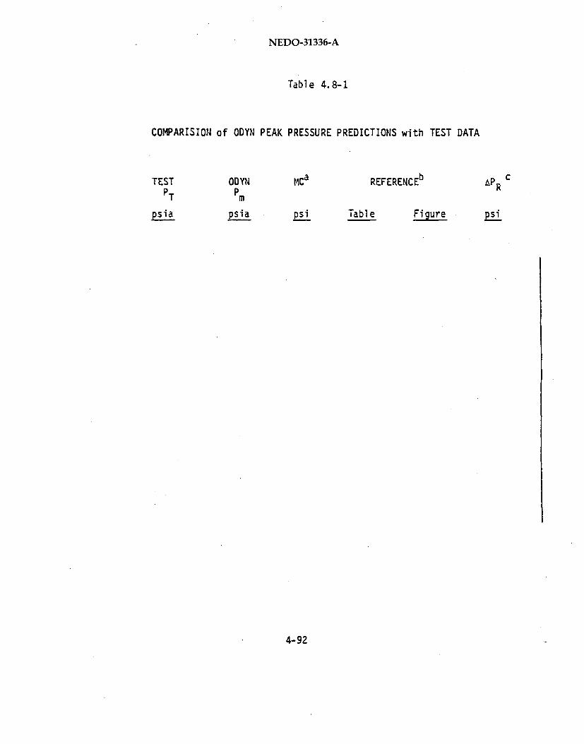
NEDO-31336-A
Table 4.8-1
COMPARISION of ODYN PEAK PRESSURE PREDICTIONS with TEST DATA
TESTP T
ODYNPm
M4Ca REFERENCEb APR
psipsi Table Fig ure
4-92

NEDO-31336-A
4-93
NEDO-31336-A
4.8.2 Model Conservatism for Thermal Margin During Fast Recirculation
Increase Events
in conclusion, the 0.10 conservatism value is clearly a cautious claim for
use in the setpoint methodology evaluation.
4-94

NEDO-31336-A
Table 4.8-2
REDY MODEL CONSERVATISM for RECIRCULATION FLOW INCREASE EVENT
4-95

NEDO-31336-A
4.8.3 Model Conservatism for the Loss of a Feedwater Heater Transient
4-96

NEDO-31336-A
Table 4.8-3
for LOSS of FW HEATING EVENTMODEL CONSERVATISM
4-97/4-98
NEDO-31336-A
4.9 NRC OPEN ITEM 5.8 - SAFETY LIMITS
Early in 1984, a presentation was made to members of the NRC Staff concern-
ing instrument setpoint methodology. In one of the transients shown the
high reactor pressure scram was utilized as the scram initiator after
failure of two other scram methods. The peak reactor pressure during this
transient was compared to a safety limit. The safety limit shown was the
ASME Emergency Limit (Service Level C). The NRC initiated an open item
expressing their concern with this limit since it was beyond the ASME upset
overpressure limit (Service Level B) defined in the specifications for each
plant.
4.9.1 Response
4-99

NEDO-31336-A
4-100

NEDO-31336-A
Previously performed analysis shows that the pressure scram setpoint is
acceptable and even provides margin to the Service Level B limit of 1375psig though the scenario only needs to meet Service Level 0 limits.
4-101/4-102

NEDO-31336-A
4.10 NRC OPEN ITEM 5.9 - SETPOINTS OUTSIDE GE NSSS SCOPE
The setpoints that are outside the scope of GE are the responsibility of
the individual utilities and they will assure that the safety criteria have
been met (as applicable).
4-103/4-104

NEDO-31336-A
5.0 REFERENCES
1. L. E. Lee, G. W. Burnette, R. Muraledharam, and B. Schneidman,
"Comparison of LOCA Evaluation tiodels Predictions with Blowdown Heat
Transfer Results", General Electric Company, March 1978 (NEDO-21836).
2. Memorandum, P.S. Check to T. Novak and R.L. Tedesco, "Safety
Evaluation for 'Qualification of the One-Dimensional Core Transient
Model for Boiling Water Reactors', NEDO-24154 and NEDE-24154 P,
Volumes I, II and III", NRC, October 22, 1980.
3. Memorandum, P.S. Check to T. Novak and R.L. Tedesco, "Supplemental
Safety Evaluation for ODYN Code", November 20, 1980.
4. Letter, B. J. Youngblood (NRC) to J. F. Carolyn (LRG), "Interim Staff
Evaluation Findings Pertaining to Setpoint Methodology for General
Electric Supplied Protection Systems Instrumentation", February
19, 1985.
5. R. B. Linford, "Analytical Methods of Plant Transient Evaluation for
the General Electric Boiling Water Reactor", General Electric Company,February 1973 (NEDO-10802).
6. ASME, Boiler and Pressure Vessel Code, Section 111, Nuclear PowerPlant Components, Division 1, Appendix G, Paragraph G-2214.3, 1972
Edition 1.
7. Letter, J.S. Charnley (GE) to F.J. Miraglia (NRC), "Loss of FeedwaterHeating Analysis", July 5, 1983.
5-1

NEDO-31336-A
8. "Assessment of BWR MIitigation of ATWS, Volume II (NUREG 0460 Alternate
No. 3)", General Electric Company, February 1981 (NEDE-24222).
9. "Full-Scale Installation, Operation and Qualification of Elbow Flow
Meters in the Main Steam Lines of Millstone Power Station," General
Electric Company, February 1980, (NEDE-25274).
10. Letter to ALL BWR licensees of Operating Reactors, From USNRC Subject"Reactor Vessel Water Level Instrumentation in BWRs" (Generic Letter
No. 84-23), October 26, 1984.
11. General Electric Company Design Spec Data Sheets for each respective
system and plant application.
12. "Qualification of the One-Dimensional Core Transient Mobdel for Boiling
Water Reactors" Volume 2, General Electric Company, October 1978,
(NEDO-24154).
13. "General Electric Standard Application for Reactor Fuel (United States
Supplements)", (GESTAR II) General Electric Company, May 1986,
(NEDE-2411-P-A-8-US).
14. S. Visweswaran, et al., "BWR Owners' Group Response to NRC Generic
Letter 83-28, Item 4.5.3", General Electric Company, January 1985,
(NEDC-30844 pages D-2 and C-3).
5-2