Embed Size (px)
Citation preview

Submitted to Proceedings of the IEEE 1
Accessing From The Sky: A Tutorial on UAVCommunications for 5G and Beyond
Yong Zeng, Member, IEEE, Qingqing Wu, Member, IEEE, and Rui Zhang, Fellow, IEEE
(Invited Paper)
Abstract—Unmanned aerial vehicles (UAVs) have found nu-merous applications and are expected to bring fertile businessopportunities in the next decade. Among various enabling tech-nologies for UAVs, wireless communication is essential and hasdrawn significantly growing attention in recent years. Comparedto the conventional terrestrial communications, UAVs’ commu-nications face new challenges due to their high altitude abovethe ground and great flexibility of movement in the three-dimensional (3D) space. Several critical issues arise, includingthe line-of-sight (LoS) dominant UAV-ground channels and re-sultant strong aerial-terrestrial network interference, the distinctcommunication quality of service (QoS) requirements for UAVcontrol messages versus payload data, the stringent constraintsimposed by the size, weight and power (SWAP) limitations ofUAVs, as well as the exploitation of the new design degreeof freedom (DoF) brought by the highly controllable 3D UAVmobility. In this paper, we give a tutorial overview of the recentadvances in UAV communications to address the above issues,with an emphasis on how to integrate UAVs into the forthcomingfifth-generation (5G) and future cellular networks. In particular,we partition our discussions into two promising research andapplication frameworks of UAV communications, namely UAV-assisted wireless communications and cellular-connected UAVs,where UAVs serve as aerial communication platforms and users,respectively. Furthermore, we point out promising directions forfuture research and investigation.
Keywords
Unmanned aerial vehicle (UAV), wireless communication, cellularnetwork, channel model, antenna model, energy efficiency, air-groundinterference, 3D placement and trajectory, optimization.
I. INTRODUCTION
Unmanned aerial vehicles (UAVs), also commonly knownas drones, are aircrafts piloted by remote control or embed-ded computer programs without human onboard. Historically,UAVs were mainly used in military applications deployed inhostile territory for remote surveillance and armed attack, toreduce the pilot losses. In recent years, the enthusiasm forusing UAVs in civilian and commercial applications has sky-rocketed, thanks to the advancement of UAVs’ manufacturingtechnologies and their reducing cost, making them more easilyaccessible to the public. Nowadays, UAVs have found nu-merous applications in a proliferation of fields, such as aerialinspection, photography, precision agriculture, traffic control,search and rescue, package delivery, telecommunications, etc.In June 2016, the U.S. Federal Aviation Administration (FAA)
Y. Zeng is with the School of Electrical and Information Engineering, TheUniversity of Sydney, Australia 2006 (e-mail: [email protected]).Q. Wu and R. Zhang are with the Department of Electrical and Com-puter Engineering, National University of Singapore, Singapore 117583 (e-mail:{elewuqq, elezhang}@nus.edu.sg). (Corresponding author: Q. Wu.)
released the operational rules for routine civilian use of smallunmanned aircraft systems (UAS) with aircraft weight lessthan 55 pounds (25 Kg) [1]. In November 2017, FAA furtherlaunched a national program in Washington, namely “DroneIntegration Pilot Program”, to explore the expanded use ofdrones, including beyond-visual-line-of-sight (BVLoS) flights,night-time operations, flights above people, etc. [2]. It isanticipated that these new guidelines and programs will spurthe further growth of global UAV industry in the coming years.The scale of the industry of UAVs is potentially enormous withrealistic predictions in the realm of 80 billion dollars for theU.S. economy alone, expected to create tens of thousands ofnew jobs within the next decade [3]. Therefore, UAVs haveemerged as a promising technology to offer fertile businessopportunities in the next decade.
In practice, there are many types of UAVs due to theirnumerous and diversified applications. While there is no singlestandard for UAV classification, UAVs can be practicallyassorted into different categories according to different criteriasuch as functionality, weight/payload, size, endurance, wingconfiguration, control methods, cruising range, flying altitude,maximum speed, energy supplying methods, etc. For example,in terms of wing configuration, fixed-wing and rotary-wingUAVs are the two main types of UAVs that have been widelyused in practice. Typically, fixed-wing UAVs have highermaximum flying speed and can carry greater payloads fortraveling longer distances as compared to rotary-wing UAVs,while their disadvantages lie in that a runway or launcheris needed for takeoff/landing as well as that hovering at afixed position is impossible. In contrast, rotary-wing UAVs areable to takeoff/land vertically and remain static at a hoveringlocation. The above different characteristics of these two typesof UAVs thus have a great impact on their respectively suitableuse cases. A detailed classification for different types of UAVshas been provided in [4]. In general, selecting a suitable typeof UAVs is crucial for accomplishing their mission efficiently,which needs to take into account their specifications as wellas the requirements of practical applications.
A. Wireless Communication with UAVs: Basic Requirements
An essential enabling technology of UAS is wireless com-munication. On one hand, UAVs need to exchange safety-critical information with various parties such as remote pilots,nearby aerial vehicles, and air traffic controller, to ensurethe safe, reliable, and efficient flight operation. This is com-monly known as the control and non-payload communication(CNPC) [7]. On the other hand, depending on their missions,
arX
iv:1
903.
0528
9v2
[ee
ss.S
P] 1
4 M
ar 2
019

Submitted to Proceedings of the IEEE 2
TABLE I: UAV communication requirements specified by 3GPP [5].
Data Type Data Rate Reliability LatencyDL (Groundstation to UAV) Command and control 60-100 Kbps 10−3 packet error rate 50 ms
UL (UAV toground station)
Command and control 60-100 Kbps 10−3 packet error rate –
Application data Up to 50 Mbps –Similar toterrestrial user
TABLE II: Communication requirements for typical UAV applications [6].
UAV Application Height coveragein meter (m)
Payload traffic latencyin millisecond (ms)
Payload data rate(DL/UL)
Drone delivery 100 m 500 ms 300 Kbps/200 KbpsDrone filming 100 m 500 ms 300 Kbps/30 MbpsAccess point 500 m 500 ms 50 Mbps/50 MbpsSurveillance 100 m 3000 ms 300 Kbps/10 MbpsInfrastructureinspection 100 m 3000 ms 300 Kbps/10 Mbps
Drone fleet show 200 m 100 ms 200 Kbps/200 KbpsPrecisionagriculture 300 m 500 ms 300 Kbps/200 Kbps
Search and rescue 100 m 500 ms 300 Kbps/6 Mbps
UAVs may need to timely transmit and/or receive mission-related data such as aerial image, high-speed video, and datapackets for relaying, to/from various ground entities such asUAV operators, end users, or ground gateways. This is knownas payload communication.
Enabling reliable and secure CNPC links is a necessity forthe large-scale deployment and wide usage of UAVs. TheInternational Telecommunication Union (ITU) has classifiedthe required CNPC to ensure safe UAV operations into threecategories [7], including:• Communication for UAV command and control: This
includes the telemetry report (e.g., flight status) from theUAV to the ground pilot, the real-time telecommand sig-naling from ground to UAVs for non-autonomous UAVs,and regular flight command update (such as waypointupdate) for (semi-) autonomous UAVs.
• Communication for air traffic control (ATC) relay: It iscritical to ensure that UAVs do not cause any safety threatto traditional manned aircraft, especially for operationsapproaching areas with high density of aircraft. To thisend, a link between air traffic controller and the groundcontrol station via the UAV, called ATC relay, is required.
• Communication supporting “sense and avoid”: The abil-ity to support “sense and avoid” ensures that the UAVmaintains sufficient safety distance with nearby aerialvehicles, terrain and obstacles.
The specific communication and spectrum requirementsin general differ for CNPC and payload communications.Recently, the 3rd Generation Partnership Project (3GPP) hasspecified the communication requirements for these two typesof links [5], which is summarized in Table I. CNPC is usuallyof low data rate, say, in the order of Kbps (Kilobits persecond), but has rather stringent requirement on high reliabilityand low latency. For example, as shown in Table I, the datarate requirement for UAV command and control is only inthe range of 60-100 Kbps for both downlink (DL) and uplink
(UL) directions, but a reliability of less than 10−3 packet errorrate and a latency less than 50 milliseconds (ms) are required.While the communication requirements of CNPC links aresimilar for different types of UAVs due to their common safetyconsideration, those for payload data are highly application-dependent. In Table II, we list several typical UAV applicationsand their corresponding data communication requirementsbased on [6].
Since the lost of CNPC link may cause catastrophic conse-quences, the International Civil Aviation Organization (ICAO)has determined that CNPC links for UAVs must operateover protected aviation spectrum [8], [9]. Furthermore, ITUstudies have revealed that to support CNPC for the forecastednumber of UAVs in the coming years, 34 MHz (Mega Hertz)terrestrial spectrum and 56 MHz satellite spectrum are neededfor supporting both line-of-sight (LoS) and beyond-LoS UAVoperations [7]. To meet such requirement, the C-band spectrumat 5030-5091 MHz has been made available for UAV CNPCat WRC (World Radiocommunication Conference)-12. Morerecently, the WRC-15 has decided that geostationary FixedSatellite Service (FSS) networks may be used for UAS CNPClinks.
Compared to CNPC, UAV payload communication usuallyhas much higher data rate requirement. For instance, to supportthe transmission of full high-definition (FHD) video from theUAV to the ground user, the transmission rate is about severalMbps, while for 4K video, it is higher than 30 Mbps. Therate requirement for UAV serving as aerial communicationplatform can be even higher, e.g., up to dozens of Gbps fordata forwarding/backhauling applications.
B. Wireless Technologies for UAV Communication
To meet both the CNPC and payload communication re-quirements in multifarious UAV applications, proper wirelesstechnologies are needed for achieving seamless connectivity
Submitted to Proceedings of the IEEE 3
TABLE III: Comparison of wireless technologies for UAV communication.
Technology Description Advantages Disadvantages
Direct linkDirect point-to-pointcommunication withground node
Simple, low costLimited range, low data rate,vulnerable to interference,non-scalable
SatelliteCommunication andInternet access viasatellite
Global coverage
Costly, heavy/bulky/energy-consuming communicationequipment, high latency, largesignal attenuation
Ad-hoc network
Dynamicallyself-organizing andinfrastructure-freenetwork
Robust and adaptable,support for highmobility
Costly, low spectrum efficiency,intermittent connectivity,complex routing protocol
Cellularnetwork
Enabling UAVcommunications byusing cellularinfrastructure andtechnologies
Almost ubiquitousaccessibility,cost-effective, superiorperformance andscalability
Unavailable in remote areas,potential interference withterrestrial communications
and high reliability/throughput for both air-to-air and air-to-ground wireless communications in the three-dimensional(3D) space. Towards this end, four candidate communicationtechnologies are listed and compared in Table III, includingi) direct link; ii) satellite; iii) ad-hoc network; and iv) cellularnetwork. In the following, we discuss the advantages as wellas limitations of each of these technologies in detail.
1) Direct Link: Due to its simplicity and low cost, thedirect-link communication between UAV and its associatedground node over the unlicensed band (e.g., the IndustrialScientific Medical (ISM) 2.4 GHz band) was most commonlyused for commercial UAVs in the past, where the groundnode can be a joystick, remote controller, or ground station.However, it is usually limited to LoS communication, whichsignificantly constrains its operation range and hinders itsapplications in complex propagation environment. For exam-ple, in urban areas, the communication can be easily blockedby e.g., trees and high-rise buildings, which results in lowreliability and low rate. Furthermore, the ground node needs toconnect to a gateway for enabling Internet access of the UAV,which may cause long delay in case of wireless data backhaul.In addition, such a simple solution is usually insecure andvulnerable to interference and jamming. Due to the abovelimitations, the simple direct-link communication cannot bea scalable solution for supporting large-scale deployment ofUAVs in the future.
2) Satellite: Enabling UAV communications by leveragingsatellites is a viable option due to their global coverage.Specifically, satellites can help relay data communicated be-tween widely separated UAVs and ground gateways, which isparticularly useful for UAVs above ocean and in remote areaswhere the terrestrial network (WiFi or cellular) coverage isunavailable. Furthermore, satellite signals can also be usedfor navigation and localization of UAVs. In WRC 2015, theconditional use of satellite communication frequencies in theKu/Ka band has been approved to connect drones to satellites,and some satellite companies such as Inmarsat have launched
satellite communication service for UAVs [10]. However,there are also several disadvantages of satellite-enabled UAVcommunications. Firstly, the propagation loss and delay arequite significant due to the long distances between satelliteand low-altitude UAVs/ground stations. This thus poses greatchallenges for meeting ultra-reliable and delay-sensitive CNPCfor UAVs. Secondly, UAVs usually have stringent size, weightand power (SWAP) constraints, and thus may not be ableto carry the heavy, bulky and energy-consuming satellitecommunication equipment (e.g., dish antenna). Thirdly, thehigh operational cost of satellite communication also hindersits wide use for densely deployed UAVs in consumer-gradeapplications.
3) Ad Hoc Network: Mobile ad-hoc network (MANET) isan infrastructure-free and dynamically self-organizing networkfor enabling peer-to-peer communications among mobile de-vices such as laptops, cellphones, walkie-talkies, etc. Such de-vices usually communicate over bandwidth-constrained wire-less links using e.g. IEEE 802.11 a/b/g/n. Each device ina MANET can move randomly over time; as a result, itslink conditions with other devices may change frequently.Furthermore, for supporting communications between two far-apart nodes, some other nodes in between need to help forwardthe data via multi-hop relaying, thus incurring more energyconsumption, low spectrum efficiency, and long end-to-enddelay. Vehicular ad hoc network (VANET) and flying ad hocnetwork (FANET) are two applications of MANET, for sup-porting communications among high-mobility ground vehiclesand UAVs in 2D and 3D networks, respectively [11]. Thetopology or configuration of an FANET for UAVs may takedifferent forms, such as a mesh, ring, star, or even a straightline, depending on the application scenario. For example, astar network topology is suitable for UAV swarm applications,where UAVs in a swam all communicate through a centralhub UAV, which may also be responsible for communicatingwith the ground stations. Although FANET is a robust andflexible architecture for supporting UAV communications in

Submitted to Proceedings of the IEEE 4
a small network, it is generally unable to provide a scalablesolution for serving massive UAVs deployed in a wide area,due to the complexities and difficulties for realizing a reliablerouting protocol over the whole network with dynamic andintermittent link connectivities among the flying UAVs.
4) Cellular Network: It is evident that the above tech-nologies generally cannot support large-scale UAV commu-nications in a cost-effective manner. On the other hand, itis also economically nonviable to build new and dedicatedground networks for achieving this goal. As such, there hasbeen significantly growing interest recently in leveraging theexisting as well as future-generation cellular networks forenabling UAV-ground communications [12]. Thanks to thealmost ubiquitous coverage of the cellular network worldwideas well as its high-speed optical backhaul and advanced com-munication technologies, both CNPC and payload communica-tion requirements for UAVs can be potentially met, regardlessof the density of UAVs as well as their distances with thecorresponding ground nodes. For example, the forthcomingfifth-generation (5G) cellular network is expected to supportthe peak data rate of 10 Gbits/s with only 1 ms round-triplatency, which in principle is adequate for high-rate and delay-sensitive UAV communication applications such as real-timevideo streaming and data relaying.
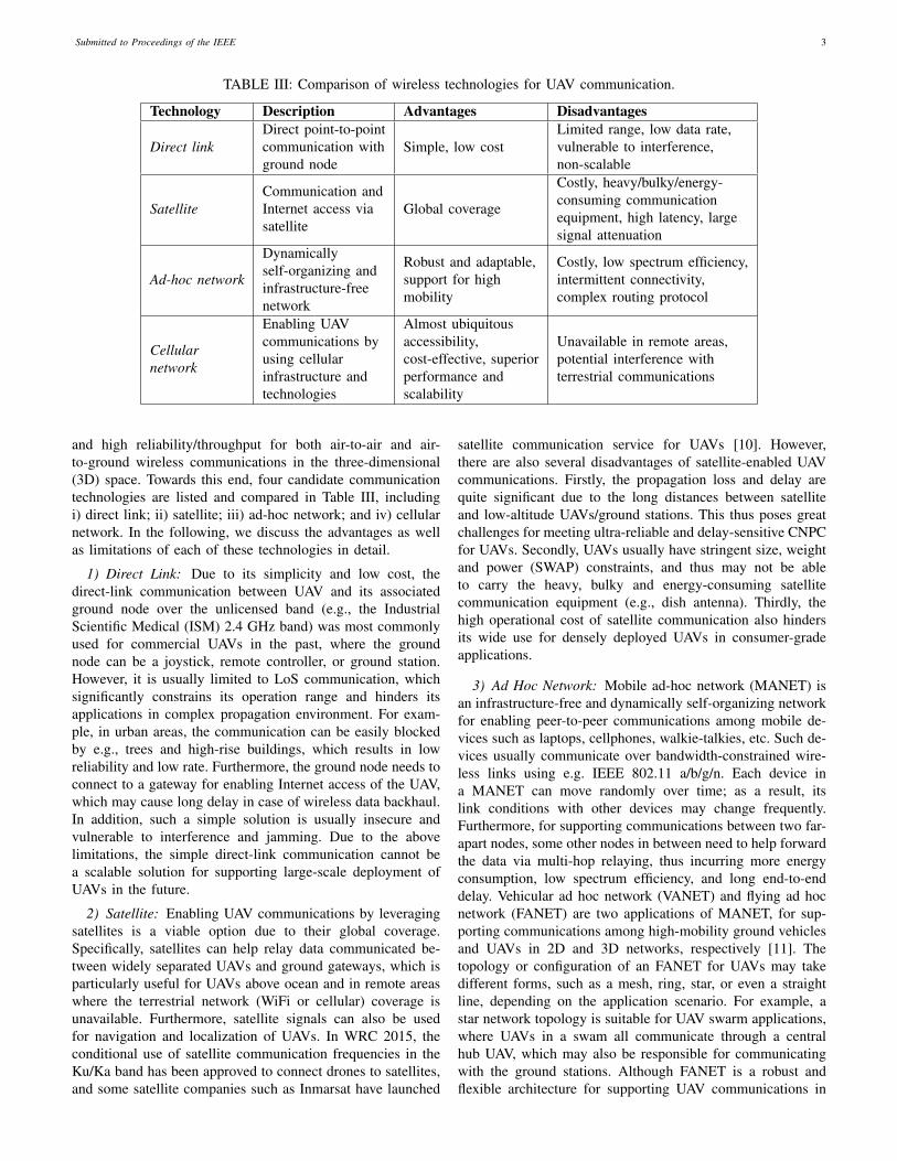
Despite the promising advantages of cellular-enabled UAVcommunications, there are still scenarios where the cellularservices are unavailable, such as in remote areas like sea,desert, forest, etc. In such scenarios, other technologies suchas the direct link, satellite and FANET, can be used to supportUAV communications beyond the terrestrial coverage of cellu-lar network. Therefore, it is envisioned that the future wirelessnetwork for supporting large-scale UAV communications willhave an integrated 3D architecture consisting of UAV-to-UAV, UAV-to-satellite and UAV-to-ground communications,as shown in Fig. 1, where each UAV may be enabled withone or more communication technologies to exploit the richconnectivity diversity in such a hybrid network.
C. The New Paradigm: Integrating UAVs into Cellular Net-work
In this subsection, we further discuss the aforementionednew paradigm of integrating UAVs into the cellular network, toprovide their full horizon of applications and benefits. In par-ticular, we partition our discussion into two main categories.On one hand, UAVs are considered as new aerial users thataccess the cellular network from the sky for communications,which we refer to as cellular-connected UAVs. On the otherhand, UAVs are used as new aerial communication platformssuch as base stations (BSs) and relays, to assist in terrestrialwireless communications by providing data access from thesky, thus called UAV-assisted wireless communications.
1) Cellular-Connected UAVs: By incorporating UAVs asnew user equipments (UEs) in the cellular network, the fol-lowing benefits can be achieved [12]. Firstly, thanks to thealmost worldwide accessibility of cellular networks, cellular-connected UAV makes it possible for the ground pilot to re-motely command and control the UAV with virtually unlimited
operation range. Besides, it also provides an effective solutionto maintain wireless connectivity between UAVs and variousother stakeholders, such as the end users and the air trafficcontrollers, regardless of their locations. This thus opens upmany new UAV applications in the future. Secondly, withthe advanced cellular technologies and authentication mech-anisms, cellular-connected UAV is expected to achieve signif-icant performance improvement over the other technologiesintroduced in the previous subsection, in terms of reliability,security, and data throughput. For instance, the current fourth-generation (4G) long term evolution (LTE) cellular networkemploys scheduling-based channel access mechanism, wheremultiple users can be served simultaneously by assigningthem orthogonal resource blocks (RBs). In contrast, WiFi(e.g., 802.11g employed in FANET) adopts contention-basedchannel access with a random backoff mechanism, whereusers are allowed to only access channels that are sensedto be idle. Thus, multiuser transmission with centralizedscheduling/control enables the cellular network to make amore efficient use of the spectrum than WiFi, especially whenthe user density is high. In addition, UAV-to-UAV communi-cation can also be realized by leveraging the available device-to-device (D2D) communications in LTE and 5G systems.Thirdly, cellular-based localization service can provide UAVs anew and complementary means in addition to the conventionalsatellite-based global positioning system (GPS) for achievingmore robust or enhanced UAV navigation performance. Lastbut not least, cellular-connected UAV is a cost-effective so-lution since it reuses the millions of cellular BSs worldwidewithout the need of building new infrastructure dedicated forUAS only. Thus, cellular-connected UAV is expected to be awin-win technology for both UAV and cellular industries, withrich business opportunities to explore in the future.
2) UAV-Assisted Wireless Communications: Thanks to thecontinuous cost reduction in UAV manufacturing and deviceminiaturization in communication equipment, it becomes morefeasible to mount compact and small-size BSs or relays onUAVs to enable flying aerial platforms to assist in terrestrialwireless communications. For instance, commercial LTE BSswith light weight (e.g., less than 4 Kg) are already available inthe market, which are suitable to be mounted on UAVs withmoderate payload. Compared to conventional terrestrial com-munications with typically static BSs/relays deployed at fixedlocations, UAV-assisted communications bring the followingmain advantages [13]. Firstly, UAV-mounted BSs/relays can beswiftly deployed on demand. This is especially appealing forapplication scenarios such as temporary or unexpected events,emergency response, search and rescue, etc. Secondly, thanksto their high altitude above the ground, UAV-BSs/relays aremore likely to have LoS connection with their ground usersas compared to their terrestrial counterparts, thus providingmore reliable links for communication as well as multiuserscheduling and resource allocation. Thirdly, thanks to thecontrollable high-mobility of UAVs, UAV-BSs/relays possessan additional degree of freedom (DoF) for communicationperformance enhancement, by dynamically adjusting theirlocations in 3D to cater for the terrestrial communicationdemands.
Submitted to Proceedings of the IEEE 5
Fig. 1: Supporting UAV communications with an integrated network architecture.
The above benefits make UAV-assisted communication apromising new technology to support the ever-increasingand highly dynamic wireless data traffic in future 5G-and-beyond cellular systems. There are abundant new applicationsin anticipation, such as for cellular data offloading in hot-spot areas (e.g., stadium during a sport event), informationdissemination and data collection in wireless sensor and In-ternet of Things (IoT) networks, big data transfer betweengeographically separated data centers, fast service recoveryafter infrastructure failure, mobile data relaying in emergencysituations or customized communications, etc.
D. UAV Communications: What’s New?
The integration of UAVs into cellular networks, either asaerial users or communication platforms, brings new designopportunities as well as challenges. Both cellular-connectedUAV communication and UAV-assisted wireless communica-tion are significantly different from their terrestrial counter-parts, due to the high altitude and high mobility of UAVs,the high probability of UAV-ground LoS channels, the dis-tinct communication quality of service (QoS) requirementsfor CNPC versus mission-related payload data, the stringentSWAP constraints of UAVs, as well as the new design DoF byjointly exploiting the UAV mobility control and communica-tion scheduling/resource allocation. Table IV summarizes themain design opportunities and challenges of cellular commu-nications with UAVs, which are further elaborated as follows.
1) High Altitude: Compared with conventional terrestrialBSs/users, UAV BSs/users usually have much higher altitude.For instance, a typical height of a terrestrial BS is around 10 mfor Urban Micro (UMi) deployment and 25 m for Urban Macro(UMa) deployment [5], whereas the current regulation alreadyallows the UAVs to fly up to 122 m [1]. For cellular-connectedUAVs, the high UAV altitude requires cellular BSs to offer 3D
aerial coverage for UAV users, in contrast to the conventional2D coverage for terrestrial users. However, existing BS an-tennas are usually tilted downwards, either mechanically orelectronically, to cater for the ground coverage as well as sup-pressing the inter-cell interference. Nevertheless, preliminaryfield measurement results have demonstrated satisfactory aerialcoverage to meet the basic communication requirements by theantenna side lobes of BSs for UAVs below 400 feet (122 m)[14]. However, as the altitude further increases, weak signalcoverage is observed, which thus calls for new BS antennadesigns and cellular communication techniques to achievesatisfactory UAV coverage up to the maximum altitude of 300m as currently specified by 3GPP [5]. On the other hand, forUAV-assisted wireless communications, the high UAV altitudeenables the UAV-BS/relay to achieve wider ground coverageas compared to their terrestrial counterparts.
2) High LoS Probability: The high UAV altitude leadsto unique air-ground channel characteristics as compared toterrestrial communication channels. Specifically, compared tothe terrestrial channels that generally suffer more severe pathloss due to shadowing and multi-path fading effects, the UAV-ground channels, including both the UAV-BS and UAV-userchannels, typically experience limited scattering and thus havea dominant LoS link with high probability. The LoS-dominantair-ground channel brings both opportunities and challengesto the design of UAV communications as compared to thetraditional terrestrial communications. On one hand, it offersmore reliable link performance between the UAV and itsserving/served ground BSs/users, as well as a pronouncedmacro-diversity in terms of more flexible UAV-BS/user asso-ciations. Moreover, as LoS-dominant links have less channelvariations in time and frequency, communication schedulingand resource allocation can be more efficiently implemented ina much slower pace as compared to that over terrestrial fading
Submitted to Proceedings of the IEEE 6
channels. On the other hand, however, it also causes strong air-ground interference, which is a critical issue that may severelylimit the cellular network capacity with coexisting aerial andterrestrial BSs/users. For example, in the UL communicationof a UAV user, it may pose severe interference to manyadjacent cells at the same frequency band due to its high-probability LoS channels with their BSs; while in the DLcommunication, the UAV user also suffers strong interferencefrom these co-channel BSs. Interference mitigation is crucialfor both frameworks of cellular-connected UAVs and UAV-assisted terrestrial communications. Furthermore, the LoS-dominant air-ground links also make UAV communicationsmore susceptible to the jamming/eavesdropping attacks bymalicious ground nodes as compared to the terrestrial commu-nications over fading channels, thus imposing a new securitythreat at the physical layer [15].
3) High 3D Mobility: Different from the terrestrial net-works where the BSs/relays are usually at fixed locationsand the users move sporadically and randomly, UAVs canmove at high speed in 3D space with partially or fullycontrollable mobility. On one hand, the high mobility of UAVsgenerally results in more frequent handovers and time-varyingwireless backhaul links with ground BSs/users. On the otherhand, it also leads to an important new design approach ofcommunication-aware UAV mobility control, such that theUAV’s position, altitude, speed, heading direction, etc., can bedynamically changed to better meet its communication objec-tives with the ground BSs/users. For example, in UAV-assistedwireless communication, UAV-BSs/relays can design theirtrajectories (i.e., locations and speeds over time) either off-lineor in real time to adapt to the locations and communicationchannels of their served ground users. Similarly, for cellular-connected UAVs, they can also adjust their trajectories basedon the locations of the ground BSs to find the best route tofulfill their mission requirements and in the meanwhile ensurea set of BSs along its trajectory to satisfy its communicationneeds. Furthermore, UAV 3D placement/trajectory design canbe jointly considered with communication scheduling andresource allocation for further performance improvement.
4) SWAP Constraints: Different from terrestrial communi-cation systems where the ground BSs/users usually have astable power supply from the grid or rechargeable battery,the SWAP constraints of UAVs pose critical limits on theirendurance and communication capabilities. For example, inthe case of UAV-assisted wireless communications, customizedBSs/relays, generally of smaller size and lighter weight as wellas with more compact antenna and power-efficient hardware ascompared to their terrestrial counterparts, need to be designedto cater for the limited payload and size of UAVs. Furthermore,besides the conventional communication transceiver energyconsumption, UAVs need to spend the additional propulsionenergy to remain aloft and move freely over the air [16], [17],which is usually much more significant than the communi-cation energy (e.g. in the order of kilowatt versus watt) forcommercial UAVs. Thus, the energy-efficient design of UAVcommunication is more involved than that for the conventionalterrestrial systems considering the communication energy only[18], [19].
E. Prior Work and Our Contribution
The exciting new opportunities in a broad range of UAVapplications have spawned extensive research recently. In par-ticular, several magazine [12,13,20]–[23] and survey [11,24]–[34] papers on wireless communications and networks withUAVs have appeared. Among them, the survey papers [24]–[26] focus on air-ground channel models and experimentalmeasurement results of UAV communications. The surveypapers [11], [27] and [28] mainly address ad hoc networksfor UAV communications by focusing on UAV-UAV com-munications. Prior work [29] gives a survey on UAV-aidedcivil applications, while the survey paper [30] discusses otherapplications of UAVs and some promising technologies forthem. In [31], the UAV-enabled IoT services are overviewedwith a particular focus on data collection, delivery, andprocessing, while in [32] the challenges in designing andimplementing multi-UAV networks for a wide range of cyber-physical applications are reviewed. The recent works [33]and [34] provide contemporary surveys of UAV applicationsin cellular networks, focusing on academic literatures andindustry activities, respectively.
Compared with the above survey papers, this paper aimsto provide a more comprehensive survey and tutorial onUAV communications, with an emphasis on the two promis-ing paradigms of cellular-connected UAVs and UAV-assistedwireless communications. Besides providing a state-of-the-artliterature survey from both academic and industrial researchperspectives, this paper provides more technically in-depthresults and discussions to facilitate and inspire future researchin this area. In particular, this tutorial features a unified andgeneral mathematical framework for UAV trajectory and com-munication co-design as well as a comprehensive overviewon the various techniques to deal with the crucial air-groundinterference issue in cellular communications with UAVs.
The rest of this paper is organized as follows. Section IIintroduces the fundamentals of UAV communications, includ-ing channel model, antenna model, UAV energy consumptionmodel, and the mathematical framework for designing UAVtrajectory and communication jointly. Section III considersUAV-assisted wireless communications, where the basic sys-tem models, performance analysis, UAV placement/trajectoryand communication co-design, as well as energy-efficientUAV communications are discussed. We also highlight thepromising new direction of learning-based UAV trajectory andcommunication design at the end of this section. In Section IV,we address the other paradigm of cellular-connected UAVs. Westart with a historical feasibility study on supporting aerialusers in cellular networks by introducing some major fieldtrials from 2G to 4G, as well as the latest standardizationefforts by 3GPP. We then give an overview on some represen-tative works evaluating the performance of the cellular networkwith newly added UAV users to draw useful insights. Last,we present promising techniques to efficiently embrace aerialusers in the cellular network including air-ground interferencemitigation and QoS-aware UAV trajectory planning. In Sec-tion V, we discuss other related topics to provide promisingdirections for future research and investigation. Finally, we

Submitted to Proceedings of the IEEE 7
TABLE IV: Opportunities and challenges of cellular communication with UAVs.
Characteristic Opportunities Challenges
High altitudeWide ground coverage as aerialBS/relay
Require 3D cellular coverage foraerial user
High LoS proba-bility
Strong and reliable communicationlink; high macro-diversity; slowcommunication scheduling andresource allocation
Severe aerial-terrestrial interference;susceptible to terrestrialjamming/eavesdropping
High 3D mobilityTraffic-adaptive movement;QoS-aware trajectory design
Handover management; wirelessbackhaul
SWAP constraint –
Limited payload and endurance;energy-efficient design; compact andlightweight BS/relay and antennadesign
conclude this paper in Section VI.Notations: In this paper, scalars and vectors are denoted
by italic letters and boldface lower-case letters, respectively.RM×1 and CM×1 denote the space of M -dimensional real-and complex-valued vectors, respectively. For a real number a,dae denotes the smallest integer greater than or equal to a. j isthe imaginary unit with j2 = −1. For a vector a, aT , aH , ‖a‖,and [a]n denote its transpose, complex conjugate transpose,Euclidean norm, and the nth component, respectively. Thenotation exp(·) denotes the exponential function. For a twicedifferentiable time-dependent vector-function x(t), x(t) andx(t) denote the first- and second-order derivatives with respectto time t, respectively. For a real-valued function f(q) withrespect to a vector q,∇f(q) denotes its gradient. For a randomvariable X , E[X] represents its statistical expectation, whilePr(E) denotes the probability of an event E. Furthermore,N (µ, σ2) represents the Gaussian distribution with mean µand variance σ2.
II. UAV COMMUNICATION FUNDAMENTALS
In this section, we present some basic mathematical mod-els pertinent to UAV communications, which are useful forresearch in both frameworks of UAVs serving as aerial usersor communication platforms. They include the channel model,antenna model, UAV energy consumption model, performancemetrics, as well as mathematic formulation for performanceoptimization via joint UAV communication and trajectorydesign.
A. Channel Model
UAV communications mainly involve three types of links,namely the ground BS (GBS)-UAV link, the UAV-groundterminal (GT) link, and the UAV-UAV link. As the com-munication between UAVs with moderate distance typicallyoccurs in clear airspace when the earth curvature is irrelevant,the UAV-UAV channel is usually characterized by the simplefree-space path loss model [35], [36].1 Therefore, we focus
1For the special case of UAV-UAV links in a UAV swarm consisting ofmany UAVs in short-distances with each other, there may exist multipath dueto the signal reflection/scattering among the UAVs.
on the channel models for GBS-UAV and UAV-GT links inthis subsection, for cellular-connected UAVs and UAV-assistedterrestrial communications, respectively. In principle, the ex-isting channel models for the extensively studied terrestrialcommunication systems can be applied to UAV communica-tions. However, as UAV systems involve transmitters and/orreceivers with altitude much higher than those in conventionalterrestrial systems, customized mathematical models havebeen developed to more accurately characterize the uniquepropagation environment for UAV communications at differentaltitude. Significant efforts have been devoted to the channelmeasurements and modelling for UAV communications, wheresome recent surveys on them can be found in e.g., [24]–[26]. Different from these existing surveys focusing on chan-nel measurement campaigns with detailed description of themeasurement setup and data processing methods, we providehere a tutorial overview on the mathematical UAV channelmodels to facilitate performance analysis and evaluation forUAV communication systems, as will be further illustrated inmore details in Section III and Section IV.
We start with the general wireless channel model for base-band communication in a frequency non-selective channel,where the complex-valued channel coefficient between a trans-mitter and a receiver can be expressed as [37]
g =√β(d)g, (1)
where β(d) accounts for the large-scale channel attenuationincluding distance-dependent path loss and shadowing, with ddenoting the distance between the transmitter and the receiver,and g is generally a complex random variable with E[|g|2] = 1accounting for the small-scale fading due to multi-path prop-agation. One classical model for β(d) is the log-distance pathloss (PL) model, where β(d)[dB] = −PL(d)[dB] with
PL(d)[dB] = 10α log10(d) +X0[dB] +Xσ[dB], (2)
where α is the path loss exponent that usually has the valuebetween 2 and 6, X0 is the path loss at a reference distanceof 1 m, Xσ ∼ N (0, σ2
X) accounts for the shadowing effectwhich is modelled as a normal (Gaussian) random variablewith zero mean and a certain variance σ2
X .For UAV communications, the choice of appropriate mod-
Submitted to Proceedings of the IEEE 8
els for the large-scale and small-scale channel parametersneeds to take into account their unique propagation condi-tions. Firstly, different from terrestrial communication systemswhere Rayleigh fading is commonly used for small-scalefading, the more general Rician or Nakagami-m small-scalefading model is more appropriate for UAV-ground communi-cations since the LoS channel component is usually present.While the above small-scale fading channel models have beenwell understood in existing literature, the modelling for thelarge-scale channel component in UAV-ground communica-tions is generally more sophisticated due to the high altitudeof UAVs and resultant 3D propagation space. Various cus-tomized models have been proposed, which can be generallyclassified into three categories, namely free-space channelmodel, models based on altitude/angle-dependent parameters,and probabilistic LoS channel model.
1) Free-Space Channel Model: For the ideal scenario inthe absence of signal obstruction or reflection, we have thefree-space propagation channel model where the effects ofshadowing and small-scale fading vanish. In this case, we have|g| = 1 and the channel power in (1) can be simplified as
β(d) =
(λ
4πd
)2
= β0d−2, (3)
where λ is the carrier wavelength, β0 ,(λ4π
)2is the channel
power at the reference distance of 1 m. With the abovefree-space path loss model, the channel power is completelydetermined by the transmitter-receiver distance (or locationsof the UAV and its communicating GBS/GT), which is easilypredictable if their locations are known. As a result, free-spacechannel model has been widely assumed in early works onoffline UAV trajectory optimization in communication systems[16,38,39].
In practice, free-space path loss model gives a reasonableapproximation in rural area where there is little blockage orscattering, and/or when the altitude of UAV is sufficiently highso that a clear LoS link between the UAV and the groundnode is almost surely guaranteed. However, for low-altitudeUAV operating in urban environment where the building heightis non-negligible as compared to UAV altitude, free-spacepropagation model is oversimplified. In this case, more refinedchannel models are needed to reflect the change of propagationenvironment as the UAV altitude varies. Two approacheshave been widely adopted to achieve this goal: using channelmodelling parameters that are dependent on UAV altitude orelevation angle, or using a probabilistic LoS channel modelby modelling the LoS and NLoS scenarios randomly butgoverned by a certain probability distribution, as discussedin the following.
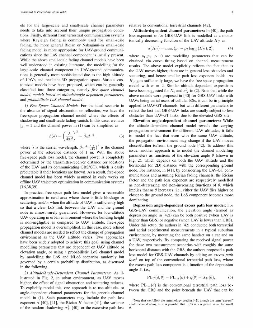
2) Altitude/Angle-Dependent Channel Parameters: As il-lustrated in Fig. 2, in urban environment, as UAV moveshigher, the effect of signal obstruction and scattering reduces.To explicitly model this, one approach is to use altitude- orangle-dependent channel parameters for the generic channelmodel in (1). Such parameters may include the path lossexponent α [40], [41], the Rician K factor [41], the varianceof the random shadowing σ2
X [40], or the excessive path loss
relative to conventional terrestrial channels [42].Altitude-dependent channel parameters: In [40], the path
loss exponent α for GBS-UAV link is modelled as a mono-tonically decreasing function of the UAV altitude HU as
α(HU ) = max (p1 − p2 log10(HU ), 2) , (4)
where p1, p2 > 0 are modelling parameters that can beobtained via curve fitting based on channel measurementresults. The above model explicitly reflects the fact that asthe UAV moves higher, there are in general less obstacles andscattering, and hence smaller path loss exponent holds. AsHU gets sufficiently large, we have the free space propagationmodel with α = 2. Similar altitude-dependent expressionshave been suggested for X0 and σ2
X in (2). Note that while theabove models were proposed in [40] for GBS-UAV links withUAVs being aerial users of cellular BSs, it can be in principleapplied to UAV-GT channels, but with different parameters toreflect the fact that GBS-UAV links are usually subject to lessobstacles than UAV-GT links, due to the elevated GBS site.
Elevation angle-dependent channel parameters: Whilethe altitude-dependent channel model reveals the varyingpropagation environment for different UAV altitudes, it failsto model the fact that even with the same UAV altitude,the propagation environment may change if the UAV movescloser/further to/from the ground node [42]. To address thisissue, another approach is to model the channel modellingparameters as functions of the elevation angle θ (shown inFig. 2), which depends on both the UAV altitude and thehorizontal (or 2D) distance with the corresponding groundnode. For instance, in [41], by considering the UAV-GT com-munications and assuming Rician fading channels, the Ricianfactor and the path loss exponent are respectively modelledas non-decreasing and non-increasing functions of θ, whichimplies that as θ increases, i.e., either the UAV flies higher orcloser to the ground node, the LoS component becomes moredominating.
Depression angle-dependent excess path loss model: ForGBS-UAV communication, the elevation angle (termed asdepression angle in [42]) can be both positive (when UAV ishigher than GBS) or negative (when UAV is lower than GBS).Under this setup, the authors in [42] conducted both terrestrialand aerial experimental measurements in a typical suburbanenvironment, by mounting the same handset on a car and ona UAV, respectively. By comparing the received signal powerfor these two measurement scenarios with roughly the samehorizontal distance with the GBS, the authors proposed a pathloss model for GBS-UAV channels by adding an excess pathloss2 on top of the conventional terrestrial path loss, wherethe excess path loss component is a function of the depressionangle θ, i.e.,
PLU (d, θ) = PLter(d) + η(θ) +XU (θ), (5)
where PLter(d) is the conventional terrestrial path loss be-tween the GBS and the point beneath the UAV that can be
2Note that we follow the terminology used in [42], though the term “excess”could be misleading as it is possible that η(θ) is a negative value for smallθ.
Submitted to Proceedings of the IEEE 9
H1
d2D
LoS path
ϴ1 ϴ2
Reflected path
H2
Fig. 2: An illustration of the UAV-ground propagation in urban environment.
obtained based on (2), η(θ) is the excess aerial path loss,and XU (θ) ∼ N
(0, σ2
U (θ))
represents the excess shadowingcomponent. Furthermore, both η(θ) and σ2
U (θ) are modelledas functions of θ as
η(θ) = A(θ − θ0) exp
(−θ − θ0
B
)+ η0, (6)
σ2U (θ) = aθ + σ0, (7)
where A,B, θ0, a, σ0 are modelling parameters that can beobtained based on curve fitting using measurement data. It wassuggested in [42] that A < 0 and thus η(θ) firstly decreasesand then increases with θ. This is due to the followingtwo effects as θ increases: on one hand, the obstruction andscattering are reduced as the UAV moves higher, while on theother hand, increased link distance and reduced GBS antennagain are incurred.
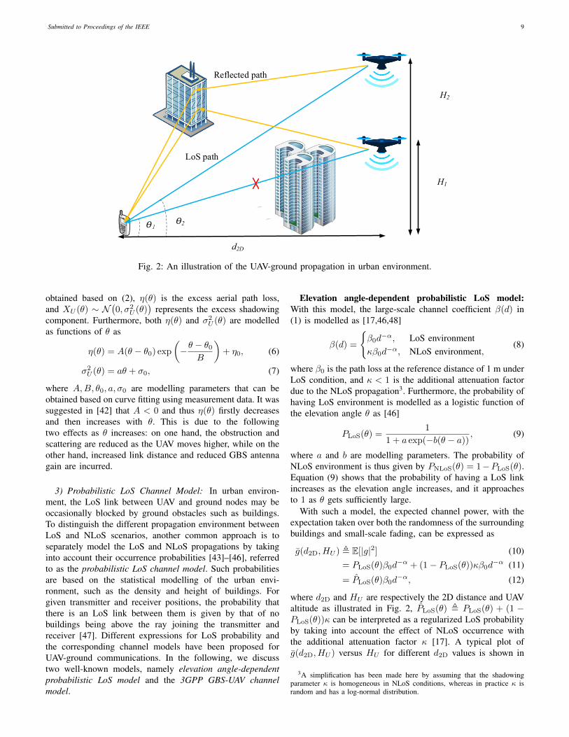
3) Probabilistic LoS Channel Model: In urban environ-ment, the LoS link between UAV and ground nodes may beoccasionally blocked by ground obstacles such as buildings.To distinguish the different propagation environment betweenLoS and NLoS scenarios, another common approach is toseparately model the LoS and NLoS propagations by takinginto account their occurrence probabilities [43]–[46], referredto as the probabilistic LoS channel model. Such probabilitiesare based on the statistical modelling of the urban envi-ronment, such as the density and height of buildings. Forgiven transmitter and receiver positions, the probability thatthere is an LoS link between them is given by that of nobuildings being above the ray joining the transmitter andreceiver [47]. Different expressions for LoS probability andthe corresponding channel models have been proposed forUAV-ground communications. In the following, we discusstwo well-known models, namely elevation angle-dependentprobabilistic LoS model and the 3GPP GBS-UAV channelmodel.
Elevation angle-dependent probabilistic LoS model:With this model, the large-scale channel coefficient β(d) in(1) is modelled as [17,46,48]
β(d) =
{β0d−α, LoS environment
κβ0d−α, NLoS environment,
(8)
where β0 is the path loss at the reference distance of 1 m underLoS condition, and κ < 1 is the additional attenuation factordue to the NLoS propagation3. Furthermore, the probability ofhaving LoS environment is modelled as a logistic function ofthe elevation angle θ as [46]
PLoS(θ) =1
1 + a exp(−b(θ − a)), (9)
where a and b are modelling parameters. The probability ofNLoS environment is thus given by PNLoS(θ) = 1−PLoS(θ).Equation (9) shows that the probability of having a LoS linkincreases as the elevation angle increases, and it approachesto 1 as θ gets sufficiently large.
With such a model, the expected channel power, with theexpectation taken over both the randomness of the surroundingbuildings and small-scale fading, can be expressed as
g(d2D, HU ) , E[|g|2] (10)= PLoS(θ)β0d
−α + (1− PLoS(θ))κβ0d−α (11)
= PLoS(θ)β0d−α, (12)
where d2D and HU are respectively the 2D distance and UAValtitude as illustrated in Fig. 2, PLoS(θ) , PLoS(θ) + (1 −PLoS(θ))κ can be interpreted as a regularized LoS probabilityby taking into account the effect of NLoS occurrence withthe additional attenuation factor κ [17]. A typical plot ofg(d2D, HU ) versus HU for different d2D values is shown in
3A simplification has been made here by assuming that the shadowingparameter κ is homogeneous in NLoS conditions, whereas in practice κ israndom and has a log-normal distribution.
Submitted to Proceedings of the IEEE 10
20 60 100 140 180 220 260 300 340 380 420 460 500 540−140
−135
−130
−125
−120
−115
−110
−105
−100
HU
(m)
Avera
ge c
hannel pow
er
(dB
)
d2D
= 200 m
d2D
= 600 m
d2D
= 1000 m
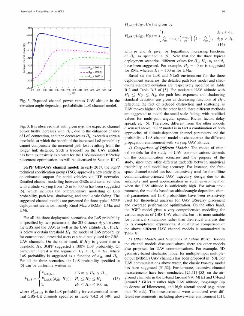
Fig. 3: Expected channel power versus UAV altitude in theelevation-angle dependent probabilistic LoS channel model.
Fig. 3. It is observed that with given d2D, the expected channelpower firstly increases with HU , due to the enhanced chanceof LoS connection, and then decreases as HU exceeds a certainthreshold, at which the benefit of the increased LoS probabilitycannot compensate the increased path loss resulting from thelonger link distance. Such a tradeoff on the UAV altitudehas been extensively exploited for the UAV-mounted BS/relayplacement optimization, as will be discussed in Section III-C.
3GPP GBS-UAV channel model: In early 2017, the 3GPPtechnical specification group (TSG) approved a new study itemon enhanced support for aerial vehicles via LTE networks.Detailed channel modelling between GBSs and aerial vehicleswith altitude varying from 1.5 m to 300 m has been suggested[5], which includes the comprehensive modelling of LoSprobability, path loss, shadowing, and small-scale fading. Thesuggested channel models are presented for three typical 3GPPdeployment scenarios, namely Rural Macro (RMa), UMa, andUMi.
For all the three deployment scenarios, the LoS probabilityis specified by two parameters: the 2D distance d2D betweenthe GBS and the UAV, as well as the UAV altitude HU . If HU
is below a certain threshold H1, the model of LoS probabilityfor conventional terrestrial users can be directly used for GBS-UAV channels. On the other hand, if HU is greater than athreshold H2, 3GPP suggested a 100% LoS probability. Ofparticular interest is the regime of H1 ≤ HU ≤ H2, whereLoS probability is suggested as a function of d2D and HU .For all the three scenarios, the LoS probability specified in[5] can be uniformly written as
PLoS =
PLoS,ter, 1.5 m ≤ HU ≤ H1,
PLoS,U(d2D, HU ), H1 ≤ HU ≤ H2,
1, H2 ≤ HU ≤ 300 m,(13)
where PLoS,ter is the LoS probability for conventional terres-trial GBS-UE channels specified in Table 7.4.2 of [49], and
PLoS,U(d2D, HU ) is given by
PLoS,U(d2D, HU ) =
{1, d2D ≤ d1,d1d2D
+ exp(−d2Dp1
)(1− d1
d2D
), d2D > d1,
(14)
with p1 and d1 given by logarithmic increasing functionsof HU as specified in [5]. Note that for the three typicaldeployment scenarios, different values for H1, H2, p1 and d1
have been suggested. For example, H2 = 40 m is suggestedfor RMa whereas H2 = 100 m for UMa.
Based on the LoS and NLoS environment for the threedeployment scenarios, the detailed path loss model and shad-owing standard deviation are respectively specified in TableB-2 and Table B-3 of [5]. For moderate UAV altitude withH1 ≤ HU ≤ H2, the path loss exponent and shadowingstandard deviation are given as decreasing functions of HU ,reflecting the fact of reduced obstruction and scattering asUAV moves higher. On the other hand, three different methodsare suggested to model the small-scale fading, with modifiedvalues for multi-path angular spread, Rician factor, delayspread, etc [5]. Therefore, different from the other modelsdiscussed above, 3GPP model is in fact a combination of bothapproaches of altitude-dependent channel parameters and theprobabilistic LoS channel model to characterize the differentpropagation environment with varying UAV altitude.
4) Comparison of Different Models: The choice of chan-nel models for the study of UAV communications dependson the communication scenarios and the purpose of thestudy, since they offer different tradeoffs between analyticaltractability and modelling accuracy. For instance, the free-space channel model has been extensively used for the offlinecommunication-oriented UAV trajectory design due to itssimplicity and good approximation in rural environment orwhen the UAV altitude is sufficiently high. For urban envi-ronment, the models based on altitude/angle-dependent chan-nel parameters and LoS probabilities have been extensivelyused for theoretical analysis for UAV BS/relay placementand coverage performance optimization. On the other hand,the 3GPP model gives a very comprehensive modelling forvarious aspects of GBS-UAV channels, but it is more suitablefor numerical simulations rather than theoretical analysis dueto its complicated expressions. A qualitative comparison ofthe above different UAV channel models is summarized inTable V.
5) Other Models and Directions of Future Work: Besidesthe channel models discussed above, there are other modelsalso proposed for UAV communications. For example, 3Dgeometry-based stochastic model for multiple-input multiple-output (MIMO) UAV channels has been proposed in [50]. ForUAV communications above water, the classic two-ray modelhas been suggested [51,52]. Furthermore, extensive channelmeasurements have been conducted [25,51]–[53] on the air-ground channels in the L-band (around 970 MHz) and C-band(around 5 GHz) at rather high UAV altitude, long-range (upto dozens of kilometers), and high aircraft speed (e.g. morethan 70 m/s). The measurements were conducted over dif-ferent environments, including above-water environment [51],

Submitted to Proceedings of the IEEE 11
TABLE V: Comparison of main UAV-ground channel models.
Channel model Description Proposed applicationscenarios Pros and Cons
Free-space channelmodel [16,38]
Channel power inversely proportionalto distance square, no shadowing orsmall-scale fading
GBS-UAV and UAV-GTchannels in rural area and/orwith very high UAV altitude
Simple, useful for offline UAVtrajectory design; oversimplifiedin urban environment
Altitude-dependentchannel parameters[40]
Channel modelling parameters suchas path loss exponent and shadowingvariance are functions of UAValtitude
GBS-UAV in urban/suburbanenvironment
Useful for theoretical analysis;fails to model the change ofpropagation environment whenUAV moves horizontally
Elevation angle-dependent channelparameters [41]
Rician factor and path loss exponentare functions of elevation angle
UAV-GT in urban/suburbanenvironment
Useful for theoretical analysis;further experimental verificationrequired
Depression angle-dependent excesspath loss model [42]
Excessive path loss depends ondepression (elevation) angle
GBS-UAV channel in suburbanenvironment
Small-scale fading model notspecified
Elevation angle-dependentprobabilistic LoSmodel [46]
Separately model LoS and NLoSpropagations; LoS probabilityincreases with elevation angle
UAV-GT channel in urbanenvironment with statisticalinformation of buildingheight/distribution
Useful for theoretical analysis;simplified shadowing; furtherexperimental verification required
3GPP GBS-UAVchannel model [5]
Separately model LoS and NLoSpropagations; LoS probability andchannel modelling parameters areboth functions of UAV altitude andhorizontal distance between GBS andUAV
GBS-UAV channel for UMa,UMi and RMa scenarios
Comprehensive models for pathloss, shadowing and small-scalefading; useful for numericalsimulations but too complicatedfor theoretical analysis or offlineUAV trajectory optimization
mountainous/hilly environment [53], and suburban and near-urban environments [52]. Based on the measurement results, amodified log-distance path loss model was proposed to accountfor the flight direction [52,53]
PL(d) = PLter(d) + ξF, (15)
where PLter(d) is the classic log-distance path loss model asgiven in (2), ξ = −1 if the aircraft travels towards the groundstation and ξ = 1 for travelling away from it, and F is asmall positive adjustment factor for direction of travel. It wasexplained in [52,53] that such a correction factor is to accountfor the slightly different orientations of the aircraft in the twotravel directions. For wide-band frequency-selective channelmodels, a tapped delay line (TDL) model has been developedin [53], which includes the LoS component, a potential groundreflection and other intermittent taps.
It is worth mentioning that channel measurements and mod-elling for UAV communications are still active and ongoingresearch. The incorporation of various other issues would bevery useful for the accurate performance analysis and practicaldesign of UAV communication systems in the future, such asthe MIMO and massive MIMO channel modelling, the channelvariations induced by UAV mobility and/or blade rotation, themillimeter wave (mmWave) UAV channel modelling [54], andthe wideband channel modelling in scattering environment.
Another important issue is channel estimation for UAV-ground communications. While the problem of acquiring theinstantaneous channel state information (CSI) has been ex-tensively studied for terrestrial communications, it deservesnew investigations for UAV communications by exploitingthe unique UAV-ground channel characteristics. For example,efficient channel estimation scheme could be designed whenit is known a priori that the deterministic LoS componentdominates, as typically the case for GBS-UAV channels in ru-rual/subrural environment, by tracking the Doppler frequency
offset induced by the UAV movement. As the performance ofchannel estimation schemes typically depends on the under-lying channel models, more research endeavor is needed fordevising efficient channel estimation schemes for the specificUAV channel models discussed above, especially for MIMOor massive MIMO based UAV communications.
B. Antenna Model
Besides channel modelling, antenna modelling at the trans-mitter/receiver is also crucial to the wireless communicationlink performance. Conventional terrestrial communication sys-tems mostly assume that the transmitter-receiver distance ismuch larger than their antennas’ height difference. As a result,signals are assumed to mainly propagate horizontally andantenna modelling mostly concerns the 2D antenna gain alongthe horizontal direction. However, 2D antenna modelling isgenerally insufficient for UAV communications, which involveaerial users or BSs with large-varying altitude. Instead, 3Dantenna modelling is often needed to take into account boththe azimuth and elevation angles for UAV-ground communi-cations.
The simplest antenna modelling leads to the isotropic model,where the antenna radiates (or receives) equal power in alldirections and the corresponding radiation pattern is a spherein 3D. Isotropic antenna is a hypothetical antenna modellingthat is mainly used for theoretical analysis as a baseline case.In practice, equal radiation in 2D only (say, in the horizontaldimension) can be easily realized (by e.g., dipole antennas),leading to the omnidirectional antenna. Isotropic or omnidi-rectional antenna modelling gives a reasonable approximationfor scenarios when the antenna gains are approximately equalfor the directions of interest. However, in modern wirelesscommunication systems, directional antennas with fixed radi-ation pattern and advanced active antenna arrays for MIMOcommunications are widely used.
Submitted to Proceedings of the IEEE 12
1) Directional Antenna with Fixed Radiation Pattern: Fordirectional antenna with fixed radiation pattern, the antennagain is completely specified by the deterministic functionG(θ, φ) with respect to the elevation and azimuth angles θ andφ, respectively. There are two common approaches to realizedirectional antenna with fixed pattern. The first one is viacarefully designing the antenna shape, such as the parabolicantennas and horn antennas. The other approach, as morecommonly seen in modern wireless communications, usesantenna arrays consisting of multiple antenna elements, whoserelative phase shifts are designed to achieve constructive signalsuperposition in desired directions. With the phase shift pre-determined and fixed, the array antenna works like a singleantenna with pre-determined antenna gain in terms of G(θ, φ).
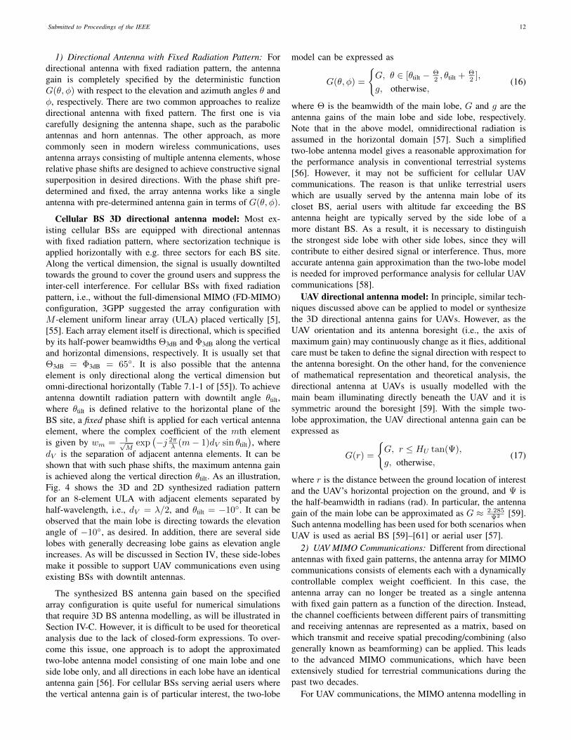
Cellular BS 3D directional antenna model: Most ex-isting cellular BSs are equipped with directional antennaswith fixed radiation pattern, where sectorization technique isapplied horizontally with e.g. three sectors for each BS site.Along the vertical dimension, the signal is usually downtiltedtowards the ground to cover the ground users and suppress theinter-cell interference. For cellular BSs with fixed radiationpattern, i.e., without the full-dimensional MIMO (FD-MIMO)configuration, 3GPP suggested the array configuration withM -element uniform linear array (ULA) placed vertically [5],[55]. Each array element itself is directional, which is specifiedby its half-power beamwidths Θ3dB and Φ3dB along the verticaland horizontal dimensions, respectively. It is usually set thatΘ3dB = Φ3dB = 65◦. It is also possible that the antennaelement is only directional along the vertical dimension butomni-directional horizontally (Table 7.1-1 of [55]). To achieveantenna downtilt radiation pattern with downtilt angle θtilt,where θtilt is defined relative to the horizontal plane of theBS site, a fixed phase shift is applied for each vertical antennaelement, where the complex coefficient of the mth elementis given by wm = 1√
Mexp
(−j 2π
λ (m− 1)dV sin θtilt), where
dV is the separation of adjacent antenna elements. It can beshown that with such phase shifts, the maximum antenna gainis achieved along the vertical direction θtilt. As an illustration,Fig. 4 shows the 3D and 2D synthesized radiation patternfor an 8-element ULA with adjacent elements separated byhalf-wavelength, i.e., dV = λ/2, and θtilt = −10◦. It can beobserved that the main lobe is directing towards the elevationangle of −10◦, as desired. In addition, there are several sidelobes with generally decreasing lobe gains as elevation angleincreases. As will be discussed in Section IV, these side-lobesmake it possible to support UAV communications even usingexisting BSs with downtilt antennas.
The synthesized BS antenna gain based on the specifiedarray configuration is quite useful for numerical simulationsthat require 3D BS antenna modelling, as will be illustrated inSection IV-C. However, it is difficult to be used for theoreticalanalysis due to the lack of closed-form expressions. To over-come this issue, one approach is to adopt the approximatedtwo-lobe antenna model consisting of one main lobe and oneside lobe only, and all directions in each lobe have an identicalantenna gain [56]. For cellular BSs serving aerial users wherethe vertical antenna gain is of particular interest, the two-lobe
model can be expressed as
G(θ, φ) =
{G, θ ∈ [θtilt − Θ
2 , θtilt + Θ2 ],
g, otherwise,(16)
where Θ is the beamwidth of the main lobe, G and g are theantenna gains of the main lobe and side lobe, respectively.Note that in the above model, omnidirectional radiation isassumed in the horizontal domain [57]. Such a simplifiedtwo-lobe antenna model gives a reasonable approximation forthe performance analysis in conventional terrestrial systems[56]. However, it may not be sufficient for cellular UAVcommunications. The reason is that unlike terrestrial userswhich are usually served by the antenna main lobe of itscloset BS, aerial users with altitude far exceeding the BSantenna height are typically served by the side lobe of amore distant BS. As a result, it is necessary to distinguishthe strongest side lobe with other side lobes, since they willcontribute to either desired signal or interference. Thus, moreaccurate antenna gain approximation than the two-lobe modelis needed for improved performance analysis for cellular UAVcommunications [58].
UAV directional antenna model: In principle, similar tech-niques discussed above can be applied to model or synthesizethe 3D directional antenna gains for UAVs. However, as theUAV orientation and its antenna boresight (i.e., the axis ofmaximum gain) may continuously change as it flies, additionalcare must be taken to define the signal direction with respect tothe antenna boresight. On the other hand, for the convenienceof mathematical representation and theoretical analysis, thedirectional antenna at UAVs is usually modelled with themain beam illuminating directly beneath the UAV and it issymmetric around the boresight [59]. With the simple two-lobe approximation, the UAV directional antenna gain can beexpressed as
G(r) =
{G, r ≤ HU tan(Ψ),
g, otherwise,(17)
where r is the distance between the ground location of interestand the UAV’s horizontal projection on the ground, and Ψ isthe half-beamwidth in radians (rad). In particular, the antennagain of the main lobe can be approximated as G ≈ 2.285
Ψ2 [59].Such antenna modelling has been used for both scenarios whenUAV is used as aerial BS [59]–[61] or aerial user [57].
2) UAV MIMO Communications: Different from directionalantennas with fixed gain patterns, the antenna array for MIMOcommunications consists of elements each with a dynamicallycontrollable complex weight coefficient. In this case, theantenna array can no longer be treated as a single antennawith fixed gain pattern as a function of the direction. Instead,the channel coefficients between different pairs of transmittingand receiving antennas are represented as a matrix, based onwhich transmit and receive spatial precoding/combining (alsogenerally known as beamforming) can be applied. This leadsto the advanced MIMO communications, which have beenextensively studied for terrestrial communications during thepast two decades.
For UAV communications, the MIMO antenna modelling in

Submitted to Proceedings of the IEEE 13
(a) 3D plot (b) 2D plot for vertical pattern intercepted at azimuth angle 0◦.
Fig. 4: A typical antenna pattern of existing cellular BSs with “fixed-pattern” array configuration.
general needs to take into account both the azimuth and ele-vation angles. With M transmitting and N receiving antennas,the MIMO channel can be modelled as
H =√β(d)
L∑l=1
a(θRl , φRl )bH(θTl , φ
Tl ), (18)
where L is the total number of multi-path, β(d) is thelarge-scale channel coefficient as discussed in Section II-A,a(·) ∈ CN×1 and b(·) ∈ CM×1 are the array response vectorsat the receiver and transmitter, respectively, θRl and φRl arerespectively the elevation and azimuth angles of arrival (AoAs)of the lth path, θTl and φTl are respectively the elevation andazimuth angles of departure (AoDs) of the lth path.
To support MIMO UAV communications (as well as thatof conventional users in high buildings), 3GPP has suggestedthe use of uniform rectangular arrays (URAs) at the cellularBSs [5], [55], with antenna elements placed along both thevertical and horizontal dimensions. For instance, for UMadeployment scenario, one suggested BS antenna configurationis (M1,M2, P ) = (8, 4, 2) [5], where M1 is the number ofantenna elements with the same polarization in each verticalcolumn, M2 is the number of columns, and P specifies thenumber of polarization dimensions, with P = 2 for crosspolarization and P = 1 for co-polarization [62]. As 2D activearrays are used, signals in both azimuth and elevation anglescan be resolved, thus enabling 3D beamforming or FD-MIMO.As will be discussed in Section IV-D, 3D beamforming is apromising technique for dealing with the strong air-groundinterference in cellular-connected UAV communications.
Conventional antenna array for MIMO communicationsrequires one radio frequency (RF) chain for each antennaelement. As the number of antennas increases as in massiveMIMO and mmWave communications, the required cost andcomplexity become prohibitive, in terms of hardware imple-mentation, signal processing, and energy consumption [63].To overcome this issue, there have been significant researchefforts on developing cost-aware MIMO transceiver architec-
tures, such as analog beamforming [64], hybrid anlog/digitalprecoding [65,66], and lens antenna array communications[67,68]. In particular, for communication environment withlimited channel paths, lens MIMO communication is able toachieve comparable performance with the fully digital MIMOcommunication, but with significantly reduced RF chain costand signal processing complexity [63]. This is particularlyappealing for UAV communications with the inherent multi-path sparsity due to the high UAV altitude, as well as theimperative needs for energy saving and cost/complexity reduc-tion for UAVs. Therefore, UAV MIMO communication withlow-cost as well as compact and energy-efficient transceiversis an importation problem that deserves further investigation.
C. UAV Energy Consumption Model
One critical issue of UAV communications is the lim-ited onboard energy of UAVs, which renders energy-efficientUAV communication particularly important. To this end,proper modelling for UAV energy consumption is crucial.Notice that besides the conventional communication-relatedenergy consumption due to e.g., signal processing, circuits,and power amplification, UAVs are subject to the additionalpropulsion energy consumption to remain aloft and movefreely. Depending on the size and payload of UAVs, thepropulsion power consumption may be much more significantthan communication-related power expenditure. For scenarioswhere the communication-related energy is non-negligible, theexisting models for communication energy consumption in theextensively studied terrestrial communication systems can beused for UAV communications. In contrast, the UAV propul-sion energy consumption is unique for UAV communication,whereas its mathematical modelling had received very littleattention in the past.
Early works considering UAV energy consumption mainlytargeted for various other applications rather than wirelesscommunication, where empirical or heuristic energy consump-tion models were usually used. For example, in [69], an
Submitted to Proceedings of the IEEE 14
UAV speed V
Pow
er
consum
ption
Total
Parasite
Induced
VmeVmr
(a) Fixed-wing
UAV speed V
Pow
er
consum
ption
Total
Parasite
Blade profile
Induced
VmeVmr
(b) Rotary-wing
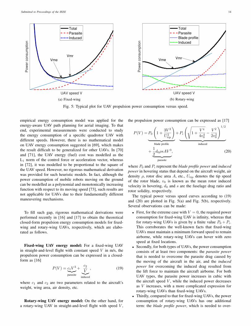
Fig. 5: Typical plot for UAV propulsion power consumption versus speed.
empirical energy consumption model was applied for theenergy-aware UAV path planning for aerial imaging. To thatend, experimental measurements were conducted to studythe energy consumption of a specific quadrotor UAV withdifferent speeds. However, there is no mathematical modelon UAV energy consumption suggested in [69], which makesthe result difficult to be generalized for other UAVs. In [70]and [71], the UAV energy (fuel) cost was modelled as theL1 norm of the control force or acceleration vector, whereasin [72], it was modelled to be proportional to the square ofthe UAV speed. However, no rigorous mathematical derivationwas provided for such heuristic models. In fact, although thepower consumption of mobile robots moving on the groundcan be modelled as a polynomial and monotonically increasingfunction with respect to its moving speed [73], such results arenot applicable for UAVs due to their fundamentally differentmaneuvering mechanisms.
To fill such gap, rigorous mathematical derivations wereperformed recently in [16] and [17] to obtain the theoreticalclosed-form propulsion energy consumption models for fixed-wing and rotary-wing UAVs, respectively, which are elabo-rated as follows.
Fixed-wing UAV energy model: For a fixed-wing UAVin straight-and-level flight with constant speed V in m/s, thepropulsion power consumption can be expressed in a closed-form as [16]
P (V ) = c1V3︸ ︷︷ ︸
parasite
+c2V︸︷︷︸
induced
, (19)
where c1 and c2 are two parameters related to the aircraft’sweight, wing area, air density, etc.
Rotary-wing UAV energy model: On the other hand, fora rotary-wing UAV in straight-and-level flight with speed V ,
the propulsion power consumption can be expressed as [17]
P (V ) =P0
(1 +
3V 2
U2tip
)︸ ︷︷ ︸
blade profile
+Pi
(√1 +
V 4
4v40
− V 2
2v20
)1/2
︸ ︷︷ ︸induced
+1
2d0ρsAV
3︸ ︷︷ ︸parasite
, (20)
where P0 and Pi represent the blade profile power and inducedpower in hovering status that depend on the aircraft weight, airdensity ρ, rotor disc area A, etc., Utip denotes the tip speedof the rotor blade, v0 is known as the mean rotor inducedvelocity in hovering, d0 and s are the fuselage drag ratio androtor solidity, respectively.
The typical power versus speed curves according to (19)and (20) are plotted in Fig. 5(a) and Fig. 5(b), respectively.Several observations can be made:
• First, for the extreme case with V = 0, the required powerconsumption for fixed-wing UAV is infinity, whereas thatfor rotary-wing UAVs is given by a finite value P0 +Pi.This corroborates the well-known facts that fixed-wingUAVs must maintain a minimum forward speed to remainairborne, while rotary-wing UAVs can hover with zerospeed at fixed locations.
• Secondly, for both types of UAVs, the power consumptionconsists of at least two components: the parasite powerthat is needed to overcome the parasite drag caused bythe moving of the aircraft in the air, and the inducedpower for overcoming the induced drag resulted fromthe lift force to maintain the aircraft airborne. For bothUAV types, the parasite power increases in cubic withthe aircraft speed V , while the induced power decreasesas V increases, with a more complicated expression forrotary-wing UAVs than fixed-wing UAVs.
• Thirdly, compared to that for fixed-wing UAVs, the powerconsumption of rotary-wing UAVs has one additionalterm: the blade profile power, which is needed to over-
Submitted to Proceedings of the IEEE 15
come the profile drag due to the rotation of blades.
A comparison of the energy consumption models for fixed-wing versus rotary-wing UAVs is summarized in Table VI.
For both UAV types, two particular UAV speeds that areof high practical interest are the maximum-endurance (ME)speed and the maximum-range (MR) speed, which are denotedas Vme and Vmr, respectively.
ME speed: By definition, the ME speed Vme is the optimalUAV speed that maximizes the UAV endurance for any givenonboard energy, which can be obtained as
Vme = arg minV≥0
P (V ). (21)
For fixed-wing UAV, Vme can be obtained based on (19) to be
Vme =(c23c1
)1/4
, whereas it can be obtained numerically forrotary-wing UAVs. Note that even for rotary-wing UAVs, hov-ering is not the most power-conserving status since Vme 6= 0in general. This may seem counter-intuitive at the first glance,but it is fundamentally due to the fact that the induced power,which is the dominant power consumption component at lowUAV speed, reduces as V increases.
MR speed: On the other hand, the MR speed Vmr is theoptimal UAV speed that maximizes the total traveling distancewith any given onboard energy, which can be obtained as
Vmr = arg minV≥0
E0(V ) ,P (V )
V. (22)
Note that E0(V ) in Joule/meter (J/m) represents the UAVenergy consumption per unit travelling distance. For fixed-wing UAVs, Vmr can be obtained in closed-form as Vmr =(c2c1
)1/4
= 31/4Vme, while it can be obtained numericallyfor rotary-wing UAVs. Alternatively, for both UAV types, Vmr
can be obtained graphically based on the power-speed curveP (V ), by drawing a tangential line from the origin to thepower curve that corresponds to the minimum slope (and hencepower/speed ratio), as illustrated in Fig. 5(b). Last, it can beshown that Vmr > Vme for both UAV types.
Extensions and directions of future Work: Note that(19) and (20) only give the instantaneous power consumptionfor UAVs in straight-and-level flight with constant speed V .For UAVs flying in 3D airspace with arbitrary trajectoryq(t) ∈ R3×1, 0 ≤ t ≤ T , with T denoting the time horizonof interest, the energy consumption in general depends onboth the 3D velocity vector v(t) = q(t) and accelerationvector a(t) = q(t). In [16], for arbitrary 2D trajectory withlevel flight (i.e., constant altitude), a closed-form expressionof energy consumption was derived for fixed-wing UAVs.The result has a nice interpretation based on the work-energyprinciple. Based on (20), similar expression can be derivedfor rotary-wing UAVs given arbitrary 2D trajectory with levelflight. However, for arbitrary 3D UAV trajectory q(t) withUAV climbing or descending over time, to the authors’ bestknowledge, no closed-form expression has been rigorouslyderived for the UAV energy consumption as a function of q(t).
One heuristic closed-form approximation might be
E(q(t)) ≈∫ T
0
P (‖v(t)‖) dt+1
2m(‖v(T )− v(0)‖2
)︸ ︷︷ ︸
∆K
+mg ([q(T )]3 − [q(0)]3)︸ ︷︷ ︸∆P
, (23)
where P (·) is given by (19) or (20) with ‖v(t)‖ being theinstantaneous UAV speed, m is the aircraft mass, and g is thegravatational acceleration. Note that the second and third termsin (23) represent the change of kinetic energy and potentialenergy, respectively. It is worth remarking that proper careshould be taken while using (23), since it ignores the effectof UAV acceleration/deceleration on the additional externalforces (or work) that must be provided by the engine. Moreresearch endeavors are thus needed to rigorously derive theUAV energy consumption with arbitrary 3D trajectory andevaluate the accuracy of the approximation in (23). In addition,the derivations in [16] and [17] assumed a zero wind speed.The energy consumption model by taking into account theeffect of wind is a challenging problem that deserves furtherinvestigation. Furthermore, it will be worthwhile to practicallyvalidate the theoretical energy consumption models by flightexperiment and measurement.
D. UAV Communication Performance Metric
For UAV communications, similar performance metricsas for conventional terrestrial communications can be used,such as link signal-to-interference-plus-noise ratio (SINR),outage/coverage probability, communication throughput, de-lay, spectral efficiency, energy efficiency, etc. In addition,in certain scenarios, new performance metrics such as UAVmission completion time [74]–[76] and energy consumption[16,17] are of practical interest. In the following, we modelthe above performance metrics in the context of UAV-groundcommunications.
1) SINR: Consider a generic UAV communication systemwith K co-channel UAVs communicating with their respectiveground nodes (GBSs or GTs). Each UAV can be either atransmitter or a receiver. Let Q = {qk}Kk=1 denote the 3Dlocations of all the K UAVs at a given time instant, andQ−k denote all other UAV locations excluding that of UAVk. For the communication link between each UAV k and itsassociated ground node, the interference scenarios are shownin Fig 6, for the cases that UAV k is a transmitter or areceiver. When UAV k is transmitting information, the SINRat its corresponding ground receiver can be expressed as (seeFig. 6(a))
γk(Q) =S(qk)
Iter + Iaer(Q−k ) + σ2, (24)
where S(qk) is the desired received signal power that changeswith the location of UAV k, Iter is the aggregate interferencefrom other transmitting ground nodes, and Iaer(Q−k ) is theaggregate interference from other transmitting UAVs whichchanges with their locations, and σ2 is the receiver noise
Submitted to Proceedings of the IEEE 16
TABLE VI: Comparison of energy consumption models for fixed-wing versus rotary-wing UAVs.
Fixed-Wing Rotary-WingConvexity with respect to speed V Convex Non-convexComponents Induced and parasite Induced, parasite, and blade profilePower at V = 0 Infinity Finite
power. On the other hand, when UAV k is receiving infor-mation, its SINR can be similarly written as
γk(Q) =S(qk)
Iter(qk) + Iaer(Q) + σ2, (25)
where the difference with (24) lies in that for this case boththe terrestrial and aerial interference powers change with qk.Such a difference has the following important implication: Forthe air-ground link with a UAV transmitter, changing the UAVlocation has an effect on its own link SINR only through thedesired signal power; while in the case with a UAV receiver, itaffects the link SINR in a more complicated manner, throughboth the desired signal and undesired interference powers. Thisobservation is useful for the design of interference-aware UAVtrajectory in practice.
In both (24) and (25), the desired signal power S(qk) canbe further written as
S(qk) = PtGt(qk)Gr(qk)β(qk)|g|2, (26)
where Pt is the transmission power, Gt and Gr are the transmitand receive antenna gains, respectively, β is the large-scalechannel power including path loss and shadowing, and g is arandom variable accounting for the small-scale fading. Notethat in (26), S(qk) explicitly depends on the UAV locationqk via the following three aspects: the transmit antenna gain,the receive antenna gain, and the large-scale channel power.Specifically, for directional transmission with either fixedantenna pattern or flexible beamforming, the relative positionbetween UAV k and its associated GBS/GT determines theAoDs and AoAs of the signal propagation, which thus affectsthe transmit and receive antenna gains. On the other hand,the dependence of the large-scale channel power β(qk) onthe UAV location qk is evident based on our discussions inSection II-A.
Similarly, the dependence of the interference from theterrestrial and other aerial users on the UAVs’ locations canbe drawn for the above two cases, respectively.
2) Outage Probability: The SINR in (24) and (25) gener-ally varies in both space and time and thus can be modelled asa random variable. For a target SINR threshold Γ, the outageprobability for the link of an arbitrary UAV k can be expressedas4
Pout,k(Q) = Pr (γk(Q) < Γ) . (27)
Note that for the given UAV locations Q, the above outageprobability needs to take into account the randomness in bothtime (e.g., due to small-scale fading) as well as space (say,due to the LoS/NLoS probabilities).
4Note that 1 − Pout,k(Q) is usually referred to as the non-outage orcoverage probability.
3) Communication Throughput: Assuming the capacity-achieving Gaussian signaling and Gaussian distributed inter-ference and noise, the achievable rate for the link of UAV kis given by Rk(Q) = log2 (1 + γk(Q)) in bits per second perHertz (bps/Hz) with each given channel realization. The av-erage achievable communication throughput over the randomchannel realizations is thus given by
Rk(Q) = E [log2 (1 + γk(Q))] . (28)
For the case of flying UAVs with the K UAVs followingcertain trajectories Q(t) = {qk(t)}Kk=1, 0 ≤ t ≤ T , theaverage communication throughput of UAV k can be writtenas
Rk (Q(t)) = E
[∫ T
0
Rk(Q(t))dt
]=
∫ T
0
Rk(Q(t))dt. (29)
4) Energy Efficiency: Energy efficiency is measured by thenumber of information bits that can be reliably communicatedper unit energy consumed, thus measured in bits/Joule [18,77]–[79]. Of particular interest for UAV communications isthe energy efficiency taking into account the unique UAV’spropulsion energy consumption. For UAV k, the link energyefficiency can be defined as
EEk(Q(t)
)=
Rk (Q(t))
E(qk(t)
)+ Ecom
, (30)
where the numerator is the average communication throughputof UAV k given in (29) that in general depends on its owntrajectory as well as those of all other co-channel UAVs dueto their interference, while the denominator includes both itspropulsion energy consumption E
(qk(t)
)given in e.g. (23)
that depends only on its own trajectory, as well as communica-tion energy consumption, denoted by Ecom. Besides the aboveper-link energy efficiency, there are also other definitionsof energy efficiency, such as the network energy efficiency,which is given by the sum communication throughput ofall UAVs’ links normalized by their total (propulsion andcommunication) energy consumption.
5) Special Case (Orthogonal Communication with IsotropicAntennas): For the purpose of illustration, we consider thespecial case with orthogonal communications over all theUAV and terrestrial links, and where all UAVs and groundnodes are equipped with isotropic antennas, under which theperformance metrics discussed above can be greatly simplified.Specifically, with orthogonal communications, all UAV linksare interference-free and therefore they can be consideredseparately. Furthermore, with isotropic transmit and receiveantennas, we have Gt(qk) = Gr(qk) = 1, ∀qk. Then thecommunication throughput of each UAV k’s link in (29) can
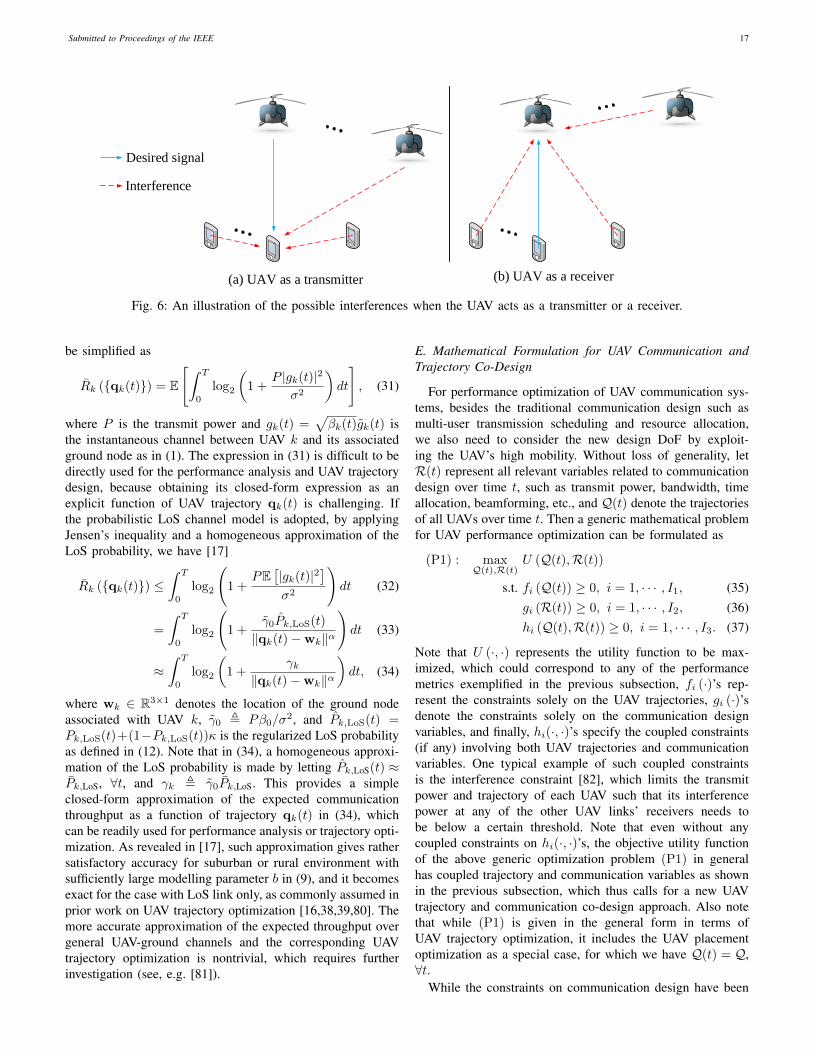
Submitted to Proceedings of the IEEE 17
Desired signal
Interference
(a) UAV as a transmitter (b) UAV as a receiver
Fig. 6: An illustration of the possible interferences when the UAV acts as a transmitter or a receiver.
be simplified as
Rk ({qk(t)}) = E
[∫ T
0
log2
(1 +
P |gk(t)|2
σ2
)dt
], (31)
where P is the transmit power and gk(t) =√βk(t)gk(t) is
the instantaneous channel between UAV k and its associatedground node as in (1). The expression in (31) is difficult to bedirectly used for the performance analysis and UAV trajectorydesign, because obtaining its closed-form expression as anexplicit function of UAV trajectory qk(t) is challenging. Ifthe probabilistic LoS channel model is adopted, by applyingJensen’s inequality and a homogeneous approximation of theLoS probability, we have [17]
Rk ({qk(t)}) ≤∫ T
0
log2
(1 +
PE[|gk(t)|2
]σ2
)dt (32)
=
∫ T
0
log2
(1 +
γ0Pk,LoS(t)
‖qk(t)−wk‖α
)dt (33)
≈∫ T
0
log2
(1 +
γk‖qk(t)−wk‖α
)dt, (34)
where wk ∈ R3×1 denotes the location of the ground nodeassociated with UAV k, γ0 , Pβ0/σ
2, and Pk,LoS(t) =Pk,LoS(t)+(1−Pk,LoS(t))κ is the regularized LoS probabilityas defined in (12). Note that in (34), a homogeneous approxi-mation of the LoS probability is made by letting Pk,LoS(t) ≈Pk,LoS, ∀t, and γk , γ0Pk,LoS. This provides a simpleclosed-form approximation of the expected communicationthroughput as a function of trajectory qk(t) in (34), whichcan be readily used for performance analysis or trajectory opti-mization. As revealed in [17], such approximation gives rathersatisfactory accuracy for suburban or rural environment withsufficiently large modelling parameter b in (9), and it becomesexact for the case with LoS link only, as commonly assumed inprior work on UAV trajectory optimization [16,38,39,80]. Themore accurate approximation of the expected throughput overgeneral UAV-ground channels and the corresponding UAVtrajectory optimization is nontrivial, which requires furtherinvestigation (see, e.g. [81]).
E. Mathematical Formulation for UAV Communication andTrajectory Co-Design
For performance optimization of UAV communication sys-tems, besides the traditional communication design such asmulti-user transmission scheduling and resource allocation,we also need to consider the new design DoF by exploit-ing the UAV’s high mobility. Without loss of generality, letR(t) represent all relevant variables related to communicationdesign over time t, such as transmit power, bandwidth, timeallocation, beamforming, etc., and Q(t) denote the trajectoriesof all UAVs over time t. Then a generic mathematical problemfor UAV performance optimization can be formulated as
(P1) : maxQ(t),R(t)
U (Q(t),R(t))
s.t. fi (Q(t)) ≥ 0, i = 1, · · · , I1, (35)gi (R(t)) ≥ 0, i = 1, · · · , I2, (36)hi (Q(t),R(t)) ≥ 0, i = 1, · · · , I3. (37)
Note that U (·, ·) represents the utility function to be max-imized, which could correspond to any of the performancemetrics exemplified in the previous subsection, fi (·)’s rep-resent the constraints solely on the UAV trajectories, gi (·)’sdenote the constraints solely on the communication designvariables, and finally, hi(·, ·)’s specify the coupled constraints(if any) involving both UAV trajectories and communicationvariables. One typical example of such coupled constraintsis the interference constraint [82], which limits the transmitpower and trajectory of each UAV such that its interferencepower at any of the other UAV links’ receivers needs tobe below a certain threshold. Note that even without anycoupled constraints on hi(·, ·)’s, the objective utility functionof the above generic optimization problem (P1) in generalhas coupled trajectory and communication variables as shownin the previous subsection, which thus calls for a new UAVtrajectory and communication co-design approach. Also notethat while (P1) is given in the general form in terms ofUAV trajectory optimization, it includes the UAV placementoptimization as a special case, for which we have Q(t) = Q,∀t.
While the constraints on communication design have been
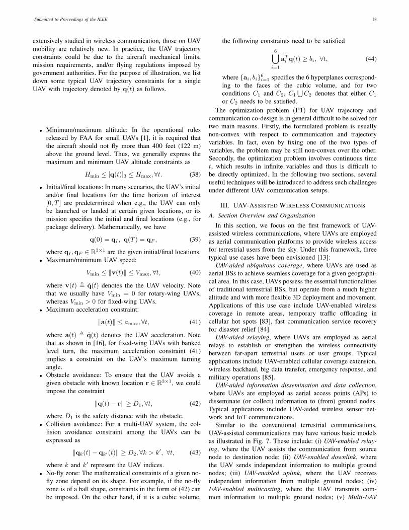
Submitted to Proceedings of the IEEE 18
extensively studied in wireless communication, those on UAVmobility are relatively new. In practice, the UAV trajectoryconstraints could be due to the aircraft mechanical limits,mission requirements, and/or flying regulations imposed bygovernment authorities. For the purpose of illustration, we listdown some typical UAV trajectory constraints for a singleUAV with trajectory denoted by q(t) as follows.
• Minimum/maximum altitude: In the operational rulesreleased by FAA for small UAVs [1], it is required thatthe aircraft should not fly more than 400 feet (122 m)above the ground level. Thus, we generally express themaximum and minimum UAV altitude constraints as
Hmin ≤ [q(t)]3 ≤ Hmax,∀t. (38)
• Initial/final locations: In many scenarios, the UAV’s initialand/or final locations for the time horizon of interest[0, T ] are predetermined when e.g., the UAV can onlybe launched or landed at certain given locations, or itsmission specifies the initial and final locations (e.g., forpackage delivery). Mathematically, we have
q(0) = qI , q(T ) = qF , (39)
where qI ,qF ∈ R3×1 are the given initial/final locations.• Maximum/minimum UAV speed:
Vmin ≤ ‖v(t)‖ ≤ Vmax,∀t, (40)
where v(t) , q(t) denotes the the UAV velocity. Notethat we usually have Vmin = 0 for rotary-wing UAVs,whereas Vmin > 0 for fixed-wing UAVs.
• Maximum acceleration constraint:
‖a(t)‖ ≤ amax,∀t, (41)
where a(t) , q(t) denotes the UAV acceleration. Notethat as shown in [16], for fixed-wing UAVs with bankedlevel turn, the maximum acceleration constraint (41)implies a constraint on the UAV’s maximum turningangle.
• Obstacle avoidance: To ensure that the UAV avoids agiven obstacle with known location r ∈ R3×1, we couldimpose the constraint
‖q(t)− r‖ ≥ D1,∀t, (42)
where D1 is the safety distance with the obstacle.• Collision avoidance: For a multi-UAV system, the col-
lision avoidance constraint among the UAVs can beexpressed as
‖qk(t)− qk′(t)‖ ≥ D2,∀k > k′, ∀t, (43)
where k and k′ represent the UAV indices.• No-fly zone: The mathematical constraints of a given no-
fly zone depend on its shape. For example, if the no-flyzone is of a ball shape, constraints in the form of (42) canbe imposed. On the other hand, if it is a cubic volume,
the following constraints need to be satisfied6⋃i=1
aTi q(t) ≥ bi, ∀t, (44)
where {ai, bi}6i=1 specifies the 6 hyperplanes correspond-ing to the faces of the cubic volume, and for twoconditions C1 and C2, C1
⋃C2 denotes that either C1
or C2 needs to be satisfied.The optimization problem (P1) for UAV trajectory and
communication co-design is in general difficult to be solved fortwo main reasons. Firstly, the formulated problem is usuallynon-convex with respect to communication and trajectoryvariables. In fact, even by fixing one of the two types ofvariables, the problem may be still non-convex over the other.Secondly, the optimization problem involves continuous timet, which results in infinite variables and thus is difficult tobe directly optimized. In the following two sections, severaluseful techniques will be introduced to address such challengesunder different UAV communication setups.
III. UAV-ASSISTED WIRELESS COMMUNICATIONS
A. Section Overview and Organization
In this section, we focus on the first framework of UAV-assisted wireless communications, where UAVs are employedas aerial communication platforms to provide wireless accessfor terrestrial users from the sky. Under this framework, threetypical use cases have been envisioned [13]:
UAV-aided ubiquitous coverage, where UAVs are used asaerial BSs to achieve seamless coverage for a given geographi-cal area. In this case, UAVs possess the essential functionalitiesof traditional terrestrial BSs, but operate from a much higheraltitude and with more flexible 3D deployment and movement.Applications of this use case include UAV-enabled wirelesscoverage in remote areas, temporary traffic offloading incellular hot spots [83], fast communication service recoveryfor disaster relief [84].
UAV-aided relaying, where UAVs are employed as aerialrelays to establish or strengthen the wireless connectivitybetween far-apart terrestrial users or user groups. Typicalapplications include UAV-enabled cellular coverage extension,wireless backhaul, big data transfer, emergency response, andmilitary operations [85].
UAV-aided information dissemination and data collection,where UAVs are employed as aerial access points (APs) todisseminate (or collect) information to (from) ground nodes.Typical applications include UAV-aided wireless sensor net-work and IoT communications.
Similar to the conventional terrestrial communications,UAV-assisted communications may have various basic modelsas illustrated in Fig. 7. These include: (i) UAV-enabled relay-ing, where the UAV assists the communication from sourcenode to destination node; (ii) UAV-enabled downlink, wherethe UAV sends independent information to multiple groundnodes; (iii) UAV-enabled uplink, where the UAV receivesindependent information from multiple ground nodes; (iv)UAV-enabled multicasting, where the UAV transmits com-mon information to multiple ground nodes; (v) Multi-UAV
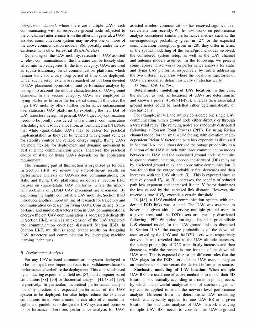
Submitted to Proceedings of the IEEE 19
interference channel, where there are multiple UAVs eachcommunicating with its respective ground node subjected tothe co-channel interference from the others. In general, a UAV-assisted communication system may involve one or more ofthe above communication models [86], possibly under the co-existence with other terrestrial BSs/APs/relays.
Depending on the UAV mobility, research on UAV-assistedwireless communications in the literature can be loosely clas-sified into two categories. In the first category, UAVs are usedas (quasi-)stationary aerial communication platforms whichremain static for a very long period of time once deployed.Under such a setup, extensive research effort has been devotedto UAV placement optimization and performance analysis bytaking into account the unique characteristics of UAV-groundchannels. In the second category, UAVs are employed asflying platforms to serve the terrestrial users. In this case, thehigh UAV mobility offers further performance enhancementover stationary UAV platforms by exploiting the new DoF ofUAV trajectory design. In general, UAV trajectory optimizationneeds to be jointly considered with multiuser communicationscheduling and resource allocation, as formulated in (P1). Notethat while (quasi-)static UAVs may be easier for practicalimplementation as they can be tethered with ground vehiclesfor stability control and reliable energy supply, flying UAVsare more flexible for deployment and dynamic movement tobest suite the communication needs. Therefore, the practicalchoice of static or flying UAVs depends on the applicationrequirement.
The remaining part of this section is organized as follows.In Section III-B, we review the state-of-the-art results onperformance analysis of UAV-assisted communications, forstatic and flying UAV platforms, respectively. Section III-Cfocuses on (quasi-)static UAV platforms, where the impor-tant problems of 2D/3D UAV placement are discussed. Byexploiting the highly controllable UAV mobility, Section III-Dintroduces another important line of research for trajectory andcommunication co-design for flying UAVs. Considering its im-portance and unique characterization in UAV communications,energy-efficient UAV communication is addressed dedicatedlyin Section III-E, which is an extension of the UAV trajectoryand communication co-design discussed Section III-D. InSection III-F, we discuss some recent results on designingUAV trajectory and communication by leveraging machinelearning techniques.
B. Performance Analysis
For any UAV-assisted communication system deployed orto be deployed, one important issue is to validate/evaluate itsperformance after/before the deployment. This can be achievedby conducting experimental field test [87], and computer-basedsimulations [88]–[90] or theoretical analysis [41,48,91]–[99],respectively. In particular, theoretical performance analysisnot only predicts the expected performance of the UAVsystem to be deployed, but also helps reduce the extensivesimulations time. Furthermore, it can also offer useful in-sights and guidelines to design the UAV system and optimizeits performance. Therefore, performance analysis for UAV-
assisted wireless communications has received significant re-search attention recently. While most works on performanceanalysis considered similar performance metrics such as thecoverage/outage probability given in (27) or the expectedcommunication throughput given in (28), they differ in termsof the spatial modelling of the aerial/ground nodes involved,the considered system setup, as well as the UAV channeland antenna models assumed. In the following, we presentsome representative works on performance analysis for staticand flying UAV platforms, respectively, by further addressingthe two different scenarios where the locations/trajectories ofUAVs are modelled deterministically or stochastically.
1) Static UAV Platform: xxDeterministic modelling of UAV location: In this case,
the number as well as locations of UAVs are deterministicand known a priori [41,48,91]–[93], whereas their associatedground nodes could be modelled either deterministically orstochastically.
For example, in [41], the authors considered one single UAVcommunicating with a ground node either directly or througha terrestrial relay. The relaying nodes are randomly distributedfollowing a Poisson Point Process (PPP). By using Ricianchannel model for the small-scale fading, with elevation angle-dependent Rician K factor and path loss exponent as discussedin Section II-A, the authors derived the outage probability as afunction of the UAV altitude with three communication modesbetween the UAV and the associated ground node: direct air-to-ground communication, decode-and-forward (DF) relayingby a selected ground relay, and cooperative communication. Itwas found that the outage probability first decreases and thenincreases with the UAV altitude HU . This is expected since atrelatively small HU , as HU increases, the benefits of reducedpath loss exponent and increased Rician K factor dominatesthe loss caused by the increased link distance. However, thereverse is true if HU exceeds a certain threshold.
In [48], a UAV-enabled communication system with un-derlaid D2D links was studied. The UAV was assumed tohover at a given altitude serving multiple ground users ina given area, and the D2D users are spatially distributedfollowing a PPP. With elevation-angle dependent probabilisticLoS channel model for the UAV-ground links as discussedin Section II-A3, the outage probabilities of the downlinkuser served by the UAV and the D2D users were respectivelyderived. It was revealed that as the UAV altitude increases,the outage probability of D2D users firstly increases and thendecreases, while the reverse is true for that of the downlinkUAV user. This is expected due to the different roles that theUAV plays for the D2D users and the UAV user, namely asan interference source versus the desired information source.
Stochastic modelling of UAV location: When multipleUAV BSs are used, one effective method is to model their 3Dlocations stochastically according to a random point process,by which the powerful analytical tool of stochastic geome-try can be applied to attain the network-level performanceanalysis. Different from the deterministic UAV modellingwhich was typically applied for one UAV BS at a givenlocation, the stochastic analysis of UAV network involvingmultiple UAV BSs needs to consider the UAV-to-ground
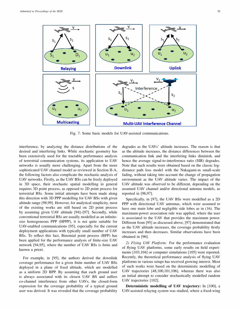
Submitted to Proceedings of the IEEE 20
Fig. 7: Some basic models for UAV-assisted communications.
interference, by analyzing the distance distributions of thedesired and interfering links. While stochastic geometry hasbeen extensively used for the tractable performance analysisof terrestrial communication systems, its application to UAVnetworks is usually more challenging. Apart from the moresophisticated UAV channel model as reviewed in Section II-A,the following factors also complicate the stochastic analysis ofUAV networks. Firstly, as the UAV BSs can be freely deployedin 3D space, their stochastic spatial modelling in generalrequires 3D point process, as opposed to 2D point process forterrestrial BSs. Some initial attempts have been made alongthis direction with 3D PPP modelling for UAV BSs with givenaltitude range [98,99]. However, for analytical simplicity, mostof the existing works are still based on 2D point processby assuming given UAV altitude [94]–[97]. Secondly, whileconventional terrestrial BSs are usually modelled as an infinite-size homogeneous PPP (HPPP), it is not quite suitable forUAV-enabled communications [95], especially for the currentdeployment applications with typically small number of UAVBSs. To reflect this fact, Binomial point process (BPP) hasbeen applied for the performance analysis of finite-size UAVnetwork [94,95], where the number of UAV BSs is finite andknown a priori.
For example, in [95], the authors derived the downlinkcoverage performance for a given finite number of UAV BSsdeployed in a plane of fixed altitude, which are modelledas a uniform 2D BPP. By assuming that each ground useris always associated with its closest UAV BS and suffersco-channel interference from other UAVs, the closed-formexpression for the coverage probability of a typical grounduser was derived. It was revealed that the coverage probability
degrades as the UAVs’ altitude increases. The reason is thatas the altitude increases, the distance differences between thecommunication link and the interfering links diminish, andhence the average signal-to-interference ratio (SIR) degrades.Note that such results were obtained based on the classic log-distance path loss model with the Nakagami-m small-scalefading, without taking into account the change of propagationenvironment as the UAV altitude varies. The impact of theUAV altitude was observed to be different, depending on theassumed UAV channel and/or directional antenna models, asreported in [96,97].
Specifically, in [97], the UAV BSs were modelled as a 2DPPP with directional UAV antennas, which were assumed tohave one main lobe and negligible side lobes as in (16). Themaximum-power association rule was applied, where the useris associated to the UAV that provides the maximum power.Different from [95] as discussed above, [97] demonstrated thatas the UAV altitude increases, the coverage probability firstlyincreases and then decreases. Similar observations have beenobtained in [96].
2) Flying UAV Platform: For the performance evaluationof flying UAV platforms, some early results on field experi-ments [103,104] or computer simulations [105] were reported.Recently, the theoretical performance analysis of flying UAVplatforms in various setups has received growing interest. Mostof such works were based on the deterministic modelling ofUAV trajectories [48,100,101,106], whereas there was alsoan initial attempt to consider stochastically modelled randomUAV trajectories [102].
Deterministic modelling of UAV trajectory: In [100], aUAV-assisted relaying system was studied, where a fixed-wing

Submitted to Proceedings of the IEEE 21
TABLE VII: A summary of representative works on performance analysis of UAV-assisted wireless communications.
ReferenceNumberof UAVBSs
Static orFlying Setup UAV channel
Model Main Findings
[41] One Static UAV BS serving groundusers with a terrestrial relay
Elevation-angledependent channelparameters, Ricianfading
Outage probability firstdecreases and then increaseswith UAV altitude
[48] One Static UAV BS with underlaidterrestrial D2D links
Elevation-angledependentprobabilistic LoS,Rayleigh fading
UAV altitude has differenteffects on the D2D user anddownlink UAV userperformances
[95] Multiple Static
UAV BSs at the samealtitude modelled as a BPP;each user associates with theclosest UAV BS
Log-distance pathloss, Nakagami-mfading
Coverage probability degradesas UAV altitude increases
[96] Multiple Static
UAV BSs modelled as a PPPwith the same altitude;directional UAV antenna;each user associates with theclosest UAV BS
Elevation-angledependentprobabilistic LoSand shadowing, nosmall-scale fading
Coverage probability firstlyincreases and then decreaseswith UAV altitude
[97] Multiple Static
UAV BSs modelled as a PPPwith a given altitude,directional UAV antenna;maximum-power basedassociation
Probabilistic LoS,Nakagami-mfading
Coverage probability firstlyincreases and then decreaseswith UAV altitude
[100] One Flying UAV relay following acircular trajectory periodically
Log-distance pathloss model, Ricianfading
With a periodic circular UAVtrajectory, variable-ratecommunication outperformsfixed-rate communication
[101] One Flying UAV BS following a linetrajectory periodically
Free space pathloss
A tradeoff between throughputand access delay
[102] Multiple FlyingUAV BSs at the samealtitude with stochasticallymodelled movement
Log-distance pathloss model,Nakagami-mfading
Stochastically flying UAV BSsachieve similar coverageperformance as static BSs, butwith significantly reduced AFD
UAV is employed to assist the communication between twoground nodes without the direct communication link. As fixed-wing UAV must maintain a forward speed to remain airborne,the UAV was assumed to fly along a circle at a constant heightand thus its location changes periodically. By considering DFrelaying and delay-sensitive applications such that the UAVforwards the information as soon as it receives and decodesit, the authors in [100] derived the link outage probabilityby assuming Rician fading channel models. It was found thatwith the periodic circular UAV trajectory, the variable-ratecommunication outperforms the fixed-rate communication.
In [101], the authors studied the UAV-assisted communica-tion system with the UAV flying cyclically among the groundusers, thus resulting in a cyclical variation pattern of eachUAV-user channel strength. By considering the basic setupwhere all ground users are located in a line and served by theUAV alternately, a tradeoff between the average access delayand the network common throughput was revealed. This studywas further extended in [106] for a hybrid wireless networkconsisting of a flying UAV BS and a conventional terrestrialBS, where the UAV flies cyclically along the cell edge to helpoffload the data traffic from the terrestrial BS.
Stochastic modelling of UAV trajectory: Different fromthe above works with deterministic UAV flying trajectories, theperformance of flying UAV BSs was analyzed in [102] withstochastic UAV flying trajectories. To this end, the stochasticgeometry analysis of [95] was extended to the case of flyingUAV BSs, where the UAVs are assumed to fly following
stochastic trajectory processes, i.e., at any snapshot, the UAVBSs can be modelled as a BPP. Two types of stochastictrajectory processes were considered, namely spiral and ovalprocesses. The results demonstrated that compared to the staticUAV BSs, the stochastically moving UAV BSs achieve com-parable coverage performance but with significantly reducedchannel average fade duration (AFD).
Table VII summarizes the above representative works onperformance analysis for both static and flying UAV-assistedwireless communication systems.
C. UAV Placement
In this subsection, we focus on (quasi-)static UAV com-munication platforms, where the locations of UAVs remainunchanged for the duration of interest. For such setups, oneimportant design problem is to determine the UAV locationsto achieve the best communication performance, which hasreceived extensive research attention recently [46,59,60,107]–[114]. Different from the conventional 2D cell planning withterrestrial BSs of typically pre-determined BS heights, thealtitude of UAV BS can be flexibly determined, thus leadingto the new 3D BS placement problems. Besides, the uniquecharacteristics of UAV-ground channels as discussed in Sec-tion II-A also need to be considered for the UAV placement.
The optimal altitude of UAV communication platformsdepends on the propagation environment and the antennamodels. For the simple isotropic antennas with the free-spacepath loss model, it is not difficult to see that the UAV placed
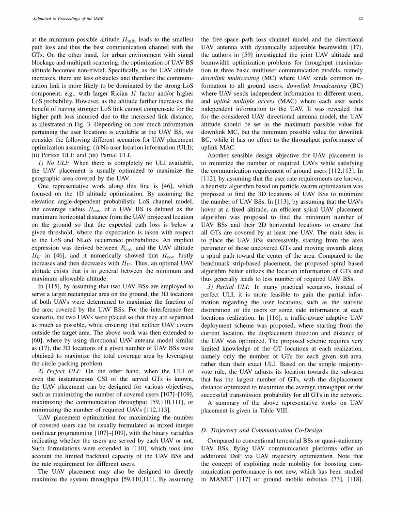
Submitted to Proceedings of the IEEE 22
at the minimum possible altitude Hmin leads to the smallestpath loss and thus the best communication channel with theGTs. On the other hand, for urban environment with signalblockage and multipath scattering, the optimization of UAV BSaltitude becomes non-trivial. Specifically, as the UAV altitudeincreases, there are less obstacles and therefore the communi-cation link is more likely to be dominated by the strong LoScomponent, e.g., with larger Rician K factor and/or higherLoS probability. However, as the altitude further increases, thebenefit of having stronger LoS link cannot compensate for thehigher path loss incurred due to the increased link distance,as illustrated in Fig. 3. Depending on how much informationpertaining the user locations is available at the UAV BS, weconsider the following different scenarios for UAV placementoptimization assuming: (i) No user location information (ULI);(ii) Perfect ULI; and (iii) Partial ULI.
1) No ULI: When there is completely no ULI available,the UAV placement is usually optimized to maximize thegeographic area covered by the UAV.
One representative work along this line is [46], whichfocused on the 1D altitude optimization. By assuming theelevation angle-dependent probabilistic LoS channel model,the coverage radius Rcov of a UAV BS is defined as themaximum horizontal distance from the UAV projected locationon the ground so that the expected path loss is below agiven threshold, where the expectation is taken with respectto the LoS and NLoS occurrence probabilities. An implicitexpression was derived between Rcov and the UAV altitudeHU in [46], and it numerically showed that Rcov firstlyincreases and then decreases with HU . Thus, an optimal UAValtitude exists that is in general between the minimum andmaximum allowable altitude.
In [115], by assuming that two UAV BSs are employed toserve a target rectangular area on the ground, the 3D locationsof both UAVs were determined to maximize the fraction ofthe area covered by the UAV BSs. For the interference-freescenario, the two UAVs were placed so that they are separatedas much as possible, while ensuring that neither UAV coversoutside the target area. The above work was then extended to[60], where by using directional UAV antenna model similaras (17), the 3D locations of a given number of UAV BSs wereobtained to maximize the total coverage area by leveragingthe circle packing problem.
2) Perfect ULI: On the other hand, when the ULI oreven the instantaneous CSI of the served GTs is known,the UAV placement can be designed for various objectives,such as maximizing the number of covered users [107]–[109],maximizing the communication throughput [59,110,111], orminimizing the number of required UAVs [112,113].
UAV placement optimization for maximizing the numberof covered users can be usually formulated as mixed integernonlinear programming [107]–[109], with the binary variablesindicating whether the users are served by each UAV or not.Such formulations were extended in [110], which took intoaccount the limited backhaul capacity of the UAV BSs andthe rate requirement for different users.
The UAV placement may also be designed to directlymaximize the system throughput [59,110,111]. By assuming
the free-space path loss channel model and the directionalUAV antenna with dynamically adjustable beamwidth (17),the authors in [59] investigated the joint UAV altitude andbeamwidth optimization problems for throughput maximiza-tion in three basic multiuser communication models, namelydownlink multicasting (MC) where UAV sends common in-formation to all ground users, downlink broadcasting (BC)where UAV sends independent information to different users,and uplink multiple access (MAC) where each user sendsindependent information to the UAV. It was revealed thatfor the considered UAV directional antenna model, the UAValtitude should be set as the maximum possible value fordownlink MC, but the minimum possible value for downlinkBC, while it has no effect to the throughput performance ofuplink MAC.
Another sensible design objective for UAV placement isto minimize the number of required UAVs while satisfyingthe communication requirement of ground users [112,113]. In[112], by assuming that the user rate requirements are known,a heuristic algorithm based on particle swarm optimization wasproposed to find the 3D locations of UAV BSs to minimizethe number of UAV BSs. In [113], by assuming that the UAVshover at a fixed altitude, an efficient spiral UAV placementalgorithm was proposed to find the minimum number ofUAV BSs and their 2D horizontal locations to ensure thatall GTs are covered by at least one UAV. The main idea isto place the UAV BSs successively, starting from the areaperimeter of those uncovered GTs and moving inwards alonga spiral path toward the center of the area. Compared to thebenchmark strip-based placement, the proposed spiral basedalgorithm better utilizes the location information of GTs andthus generally leads to less number of required UAV BSs.
3) Partial ULI: In many practical scenarios, instead ofperfect ULI, it is more feasible to gain the partial infor-mation regarding the user locations, such as the statisticdistribution of the users or some side information at eachlocations realization. In [116], a traffic-aware adaptive UAVdeployment scheme was proposed, where starting from thecurrent location, the displacement direction and distance ofthe UAV was optimized. The proposed scheme requires verylimited knowledge of the GT locations at each realization,namely only the number of GTs for each given sub-area,rather than their exact ULI. Based on the simple majority-vote rule, the UAV adjusts its location towards the sub-areathat has the largest number of GTs, with the displacementdistance optimized to maximize the average throughput or thesuccessful transmission probability for all GTs in the network.
A summary of the above representative works on UAVplacement is given in Table VIII.
D. Trajectory and Communication Co-Design
Compared to conventional terrestrial BSs or quasi-stationaryUAV BSs, flying UAV communication platforms offer anadditional DoF via UAV trajectory optimization. Note thatthe concept of exploiting node mobility for boosting com-munication performance is not new, which has been studiedin MANET [117] or ground mobile robotics [73], [118].

Submitted to Proceedings of the IEEE 23
TABLE VIII: A summary of representative works on UAV placement.
ReferenceNumberof UAVBSs
Design variable Design Objective Main techniques
[46] Single UAV 1D altitude Maximize coverage areaImplicit expression betweencoverage radius and UAValtitude
[115] Two UAVs 3D locationGiven a target rectangular area,maximize the fraction of coverage areausing two UAV BSs
Maximum separation of thetwo UAV BSs subject tocoverage area constraint
[107]–[109] Single UAV 3D location Given user locations, maximize thenumber of served users
Mixed-integer nonlinearprogramming
[60] MultipleUAVs 3D location Maximize the total coverage area Circle packing
[110] Single UAV 3D locationWith UAV backhaul capacity constraint,maximize the number of served usersor sum-rate
Branch-and-bound method
[111] Single UAV 2D locationWith UAV serving as relay, maximizethe throughput or minimizecommunication power
Smart local search for LoSpropagation
[59] Single UAV 3D locationJoint altitude and beamwidthoptimization for three basic multiusercommunication models
Closed-form throughputexpressions in terms of UAValtitude and beamwidth
[112] MultipleUAVs 3D location Minimize the number of UAVs to satisfy
the user rate requirement Particle swarm optimization
[113] MultipleUAVs 2D location Minimize the number of UAVs to ensure
that all GTs are covered Spiral BS placement
[116] Single UAV 2D location
Optimize UAV displacement directionand distance for maximizing averagethroughput or success transmissionprobability
UAV displacement to thesub-area with the most users
However, there are some important differences between suchsystems and the UAV communication system. Firstly, nodesmoving on the ground are usually subject to many obstacles,which greatly limits their flexibility for path adaption. There-fore, most existing works on exploiting ground node mobilityassumed either the random mobility model [117] or determin-istic mobility along pre-determined path [118]. In contrast,UAVs moving in 3D airspace offers more design DoF inpath/trajectory optimization for communication performanceimprovement. Secondly, due to the generally rich scatteringenvironment, the wireless channels for ground robotic commu-nications usually suffer from severe fading, which is difficultto be efficiently predicted at any location. In contrast, theUAV-ground communications often contain strong LoS link,making it easier for channel prediction and thus facilitatingthe offline trajectory optimization. Last but not least, robotsand UAVs differ significantly in terms of energy consumptionmodel, as discussed in Section II-C. The above differencesare summarized in Table IX, which render the communication-aware UAV trajectory optimization significantly different fromthat for the traditional terrestrial communications.
For UAV-assisted communications, the UAV trajectory op-timization is in general closely coupled with communicationscheduling and resource allocation, for which a generic opti-mization problem has been formulated in Section II-E. Notethat problem (P1) is difficult to be efficiently and optimallysolved due to its non-convexity in general. In the following, wepresent several useful techniques to address problem (P1) forUAV-assisted communications. In particular, we first presentthe classic travelling salesman problem (TSP) and pickup-and-deliver problem (PDP) as two useful techniques for initialUAV path planning, and then introduce the more general
optimization framework with block coordinate descent (BCD)and successive convex approximation (SCA) techniques.
1) TSP and PDP for Initial Path Planning: In general, UAVtrajectory optimization involves two aspects: path planningto determine the flying route, and speed optimization thatessentially determines how much time should be spent oneach location along the route. While path planning has beenextensively studied for UAV systems, early works mainly fo-cused on UAV navigation applications, rather than targeting foroptimizing the communication performance [70,119]–[121].For such scenarios, mixed-integer linear program (MILP) hasbeen shown to be an effective approach [70,71,122,123].Recently, there have been a handful of works on UAV pathplanning for communication purposes by partially optimizingsome of the trajectory parameters. For example, in [124]and [125], by assuming that the UAV flies with a constantspeed, the UAV’s heading (or flying direction) was optimizedfor UAV-based wireless relaying and uplink communications,respectively. In [126], a UAV-based mobile relay node wasconsidered for forwarding independent data to different usergroups. The data downloading volume as well as the relaytrajectory in terms of the visiting sequence to the differentuser groups were optimized by a genetic algorithm. In [127]and [128], the deployment/movement of UAVs was optimizedto improve the network connectivity of a UAV-assisted ad-hocnetwork. More recently, the use of more powerful optimizationtechniques for communication-aware UAV trajectory designhas received growing interest, discussed as follows.
Intuitively, for enhancing the communication link quality,the UAV should move closer to its communicating GT. Thisnot only reduces the link distance, but also increases thelikelihood of establishing a LoS communication link with it,

Submitted to Proceedings of the IEEE 24
TABLE IX: Exploiting mobility in UAV versus terrestrial communication systems.
Terrestrial System UAV System
Mobility
• Nodes usually move randomly(e.g., in a MANET)
• Nodes move with predeterminedpath (e.g., mobile robotics)
• Very restrictive path planning
• UAV mobility highly controllable/predictable
• More flexible path adaptation in 3Dspace
Communicationchannel
• Severe shadowing and multipathfading
• Difficult to predict offline
• Less shadowing and fading• More predictable
Energy consumption• Polynomial and increasing
function of speed • More complicated (see Section II-C)
D
HU
V
𝜃
Fig. 8: A point-to-point link with the UAV flying towards theGT.
especially in dense urban environment. As a toy example toillustrate this fact, we consider a basic point-to-point commu-nication setup with a UAV at fixed altitude HU communicatingwith a static ground node, with their initial horizontal distancedenoted by D, as shown in Fig. 8. Fig. 9 plots the channelpath loss, the LoS probability, and the average channel powerversus time as the UAV flies towards the ground node with aconstant speed V . Note that the channel path loss in Fig. 9(a) isbased on the classical log-distance path loss model in (2) byaveraging over the shadowing, whereas the average channelpower is obtained by averaging over the occurrence of LoSand NLoS realizations, with the elevation angle-dependent LoSprobability model given in (9). The following parameters areused: D = 1000 m, HU = 100 m, V = 20 m/s, α = 2.3,X0[dB] = 50 dB, a = 10, b = 0.6, and κ = 0.01. It isobserved that as the UAV moves closer to the ground node,the channel path loss in Fig. 9(a) is significantly improved byabout 23 dB for both LoS and NLoS cases, and there is anoverall gain of about 40 dB shown in Fig. 9(c) for the averagechannel power, due to the additional benefit of enhancedLoS probability as shown in Fig. 9(b). This demonstrates thepromising benefit of UAV trajectory design to enhance thechannel quality, especially for delay-tolerant applications sothat there is sufficient time for the UAV to move towards itsserved GTs. Motivated by this, in the following, we discusstwo useful techniques for UAV path planning, following theprinciple of bringing the UAV to each of its served GTs as
closer as possible. Such techniques are useful to find an initialUAV flying path, which can be used for trajectory initializationfor the more refined UAV trajectory and communication jointoptimization to be discussed in Section III-D2.
Travelling salesman problem (TSP): To best exploit theUAV mobility for multiuser communications, the UAV ingeneral needs to fly sequentially towards multiple GTs servedby it. Intuitively, the sooner the UAV reaches each of theGTs, the more time will be left for the UAV to enjoy thebest communication links with them. In this regard, a closelyrelated problem is the celebrated TSP [129]–[132], whichcan be applied to determine the UAV flying path as wellas the serving order of the GTs, as illustrated in Fig. 10(a).The standard TSP is described as follows: given a set ofcities and the distances between each pair of the cities, atraveler wishes to start and end at the same city and visiteach city exactly once. The problem then aims to find theroute (or the sequence of visited cities) such that the totaltraveling distance is minimized. TSP is known to be NP-hard,but various efficient algorithms have been proposed to findhigh-quality solutions [130]–[132], e.g., via solving binaryinteger problems. Note that the standard TSP algorithms dealwith the scenario that the traveller/UAV needs to return tothe initial city/location where it starts the tour. However, forUAV communications, the UAV needs not necessarily returnto the initial location, and its initial/final location might bepre-specified, as in [16,38]. In this case, variations of TSPalgorithms can be applied by adding dummy cities/GTs whosedistances with the existing cities/GTs are properly set [74].
TSP is feasible only when the given UAV operation durationT is sufficiently large so that the UAV can reach all GTs.Besides, in certain scenarios, it is simply unnecessary for theUAV to reach exactly on top of each GT (e.g., when onlyfew data needs to be collected from some GTs). In this case,another closely related problem is the TSP with neighborhood(TSPN), as illustrated in Fig. 10(b). TSPN is a generalizationof TSP in the sense that the traveller does not have to visiteach city/GT exactly, but needs to reach a given neighborhoodregion around the city/GT. TSPN is also NP hard, withvarious algorithms proposed to obtain approximate solutions[74,133,134]. In fact, in the context of UAV communications,the resultant problem is even more general than TSPN, as thesize (radius) of each neighborhood area can also be a design

Submitted to Proceedings of the IEEE 25
0 5 10 15 20 25 30 35 40 45 50−140
−135
−130
−125
−120
−115
−110
−105
−100
−95
t (s)
Pat
h lo
ss (
dB)
LoSNLoS
(a)
0 5 10 15 20 25 30 35 40 45 500
0.1
0.2
0.3
0.4
0.5
0.6
0.7
0.8
0.9
1
t (s)
LoS
pro
babi
lity
(b)
0 5 10 15 20 25 30 35 40 45 50−140
−135
−130
−125
−120
−115
−110
−105
−100
−95
t (s)
Ave
rage
cha
nnel
pow
er (
dB)
(c)
Fig. 9: Variation of channel quality as UAV flies towards the GT: (a) Channel path loss for LoS and NLoS conditions; (b) LoSprobability; (c) Average channel power.
qF
q0
u2
u1
u3
u4
u5
u6
(a) Travelling salesman problem.
u6
u4
u3
u2
u1
u5
qF
q0
(b) Travelling salesman problem withneighbourhood.
D1
D3
qF
q0
D2
S2
S3
S1
(c) Pickup and delivery problem with 3source-destination pairs.
Fig. 10: TSP/TSPN and PDPN for UAV initial path planning. q0 and qF denote the pre-determined initial and final locations,respectively.
variable depending on the communication requirement. Oneuseful method for addressing such problems is as follows:Firstly, solve the TSP based on the K cities/GTs to obtainthe visiting order, by ignoring the neighborhood regions. Thenwith the obtained order, use convex optimization techniques toobtain the optimal visiting locations inside the neighborhoodregions. This method was firstly proposed in [74], and waslater applied in various other setups [17,86]. In fact, the aboveprocess for alternately updating the visiting order and thevisiting locations can be repeated until convergence is reached.Another variation of TSP is the selective TSP [135], alsoknown as the orienteering problem [136], where instead ofvisiting all nodes (or neighborhood regions), the goal is todetermine a path and a subset of the nodes (or neighborhoodregions) for visiting to maximize a certain utility, such asthe number of nodes (or neighborhood regions) visited withina finite duration. This technique was applied in [137] fortrajectory design for UAV-enabled distributed estimation viamaximizing the number of sensors visited by the UAV withina given time horizon.
Pickup-and-delivery problem (PDP): For UAV-enabledmobile relaying, we usually have the additional information-causality constraint [38,86], i.e., the UAV needs to firstlyreceive data from a source node before forwarding to its
corresponding destination node. In this case, a useful approachfor determining the UAV flying path is by solving the PDP.PDP can be regarded as another generalization of TSP, withthe additional precedence constraints, i.e., for each pair ofsource-destination nodes, the UAV needs to firstly visit thesource node before the destination node to meet the aboveinformation-causality constraint. PDP is also NP hard, butvarious algorithms have been proposed to yield high-qualityapproximate solutions. Furthermore, in the general scenariowhere the given UAV operation duration T is insufficient tovisit all the GTs, the extended PDP with neighborhood (PDPN)can be applied to obtain the visiting order of the GTs, asillustrated in Fig. 10(c).
2) Joint Trajectory and Communication Optimization:While TSP and PDP are useful techniques to determine theinitial UAV flying path or serving order of the GTs, they arein general suboptimal for the generic problem (P1). On onehand, the UAV flying trajectory needs to take into accountthe communication performance more explicitly, which alsodepends on the communication user scheduling and resourceallocation with any given UAV trajectory. On the other hand, inpractical scenarios where UAVs are subject to various mobilityconstraints such as those exemplified in Section II-E, thesimple TSP and PDP solutions, which ignore such constraints,may lead to infeasible UAV path. To tackle such issues, it is
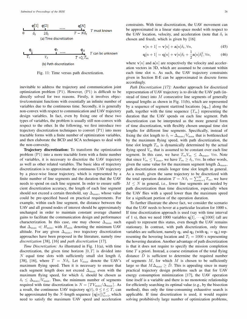
Submitted to Proceedings of the IEEE 26
Fig. 11: Time versus path discretization.
inevitable to address the trajectory and communication jointoptimization problem (P1). However, (P1) is difficult to bedirectly solved for two reasons. Firstly, it involves objec-tive/constraint functions with essentially an infinite number ofvariables due to the continuous time. Secondly, it is generallynon-convex with respect to communication and UAV trajectorydesign variables. In fact, even by fixing one of these twotypes of variables, the problem is usually still non-convex withrespect to the other. In the following, we first introduce twotrajectory discretization techniques to convert (P1) into moretractable forms with a finite number of optimization variables,and then elaborate the BCD and SCA techniques to deal withthe non-convexity.
Trajectory discretization: To transform the optimizationproblem (P1) into a more tractable form with a finite numberof variables, it is necessary to discretize the UAV trajectoryas well as other related variables. The basic idea of trajectorydiscretization is to approximate the continuous UAV trajectoryby a piece-wise linear trajectory, which is represented by afinite number of line segments and the duration that the UAVneeds to spend on each line segment. In order to ensure suffi-cient discretization accuracy, the length of each line segmentshould not exceed a certain threshold, say ∆max, whose valuecould be pre-specified based on practical requirements. Forexample, within each line segment, the distance between theUAV and all ground nodes of interest should be approximatelyunchanged in order to maintain constant average channelgains to facilitate the communication design and performancecharacterization. In this case, one may choose ∆max suchthat ∆max � Hmin, with Hmin denoting the minimum UAValtitude. For any given ∆max, two trajectory discretizationapproaches have been proposed in the literature, namely timediscretization [38], [16] and path discretization [17].
Time Discretization: As illustrated in Fig. 11(a), with timediscretization, the given time horizon [0, T ] is divided intoN equal time slots with sufficiently small slot length δt[38], [16], where T = Nδt. Let Vmax denote the UAV’smaximum flying speed. Then it is necessary to ensure thateach segment length does not exceed ∆max even with themaximum flying speed, for which δt should be chosen asδt ≤ ∆max/Vmax. Thus, the minimum number of segmentsrequired with time discretization is N = dTVmax/∆maxe. Asa result, the continuous UAV trajectory q(t), 0 ≤ t ≤ T , canbe approximated by the N -length sequence {q[n]}Nn=1, whichneed to satisfy the maximum UAV speed and acceleration
constraints. With time discretization, the UAV movement canbe approximated in a linear state-space model with respect tothe UAV location, velocity, and acceleration (note that δt ischosen and fixed), which is given by [16]
v[n+ 1] = v[n] + a[n]δt,∀n, (45)
q[n+ 1] = q[n] + v[n]δt +1
2a[n]δ2
t ,∀n, (46)
where v[n] and a[n] are respectively the velocity and acceler-ation vectors in 3D, which are assumed to be constant withineach time slot n. As such, the UAV trajectory constraintsgiven in Section II-E can be approximated in discrete formsaccordingly.
Path Discretization [17]: Another approach for discretizedrepresentation of UAV trajectory is to divide the UAV path (in-stead of time) into M consecutive line segments of generallyunequal lengths as shown in Fig. 11(b), which are representedby a sequence of segment start/end locations {qm} along thepath, together with the time sequence {Tm} representing theduration that the UAV spends on each line segment. Pathdiscretization can be interpreted as the more general formof time discretization, with flexibly chosen unequal time slotlengths for different line segments. Specifically, instead offixing the slot length to δt = ∆max/Vmax that is bottleneckedby the maximum flying speed, with path discretization, thetime slot length Tm is dynamically determined by the actualflying speed Vm that is assumed to be constant over each linesegment. In this case, we have TmVm ≤ ∆max, ∀m. Notethat since Vm ≤ Vmax, we have Tm ≥ δt, ∀m. In other words,given the same value for the maximum segment length ∆max,path discretization entails longer time slot length in general.As a result, given the same trajectory to be discretized withthe total operation duration T = Nδt =
∑Mm=1 Tm, we have
M ≤ N in general, i.e., fewer line segments are needed bypath discretization than time discretization, especially whenthe UAV flies with a speed lower than the maximum speedfor a significant portion of the operation duration.
To further illustrate the above fact, we consider the scenariothat the UAV needs to hover at a particular location for 1000 s.If time discretization approach is used (say with time intervalof 1 s), then we need 1000 variables q[1], · · ·q[1000] (all areequal) to represent this status, even though the UAV remainsstationary. In contrast, with path discretization, only threevariables are sufficient, namely q1 and q2 (with q1 = q2) rep-resenting the hovering location and T1 = 1000 s representingthe hovering duration. Another advantage of path discretizationis that it does not require to specify the mission completiontime T a priori. Instead, a coarse estimation of the total flyingdistance D is sufficient to determine the required numberof segments M , for which M is chosen to be sufficientlylarge so that M∆max ≥ D. This is appealing since in manypractical trajectory design problems such as that for UAVenergy consumption minimization [17], the UAV operationtime itself is a variable and there is no monotonic relationshipfor efficiently searching its optimal value (e.g., by the bisectionmethod), thus only the time-consuming exhaustive search isapplicable. If time discretization is used, it would requiresolving prohibitively large number of optimization problems,

Submitted to Proceedings of the IEEE 27
TABLE X: Comparison between time and path discretization.
Time discretization Path discretization
Pros
• Equal time slot length• Linear state-space representation• Incorporate the maximum
acceleration constraint easily
• Fewer variables if UAV hovers orflies slowly most of the time
• No need to know mission completiontime T a priori
Cons
• Excessively large number of timeslots when UAV hovers or movesslowly
• Need to know mission completiontime T a priori
• Difficult to incorporate the maximumacceleration constraint
• More variables if UAV flies withhigh/maximum speed most of thetime
each for a pre-assumed and fixed N , which is impractical.On the other hand, note that time discretization also has
its own merit. First, as the time interval δt is fixed, timediscretization leads to the simple linear state-space model asgiven in (45) and (46), which can easily handle the UAVmaximum acceleration constraint. In contrast, such linearrelationship is not preserved for path discretization with {Tm}also being the optimization variables. Second, if ignoring theacceleration variable, time discretization requires only onevariable for each line segment, namely the UAV locations{q[n]}, as the UAV velocity for each line segment n canbe directly obtained as v[n] = (q[n + 1] − q[n])/δt withδt given. By contrast, path discretization needs two variablesfor each line segment (namely both the UAV end locationand time duration). Thus, if given the same number of linesegments, i.e., N = M (e.g., when the UAV always flies at itsmaximum speed during the operation), then path discretizationneeds to double the number of variables as compared to timediscretization. The comparison of these two UAV trajectorydiscretization techniques is summarized in Table X.
By applying the above trajectory discretization techniques,the optimization problem (P1) can be transformed into thefollowing generic form with a finite number of variables:
(P2) : max{Q[n]},{R[n]}
U ({Q[n]}, {R[n]})
s.t. fi ({Q[n]}) ≥ 0, i = 1, · · · , I1, (47)gi ({R[n]}) ≥ 0, i = 1, · · · , I2, (48)hi ({Q[n]}, {R[n]}) ≥ 0, i = 1, · · · , I3.
(49)
In the above, {Q[n]} and {R[n]} denote the discretized UAVtrajectories and communication design variables, respectively.
BCD and SCA for resource and trajectory optimiza-tion: Problem (P2) involves the joint optimization of UAVtrajectory and communication resource allocation, which isusually non-convex and difficult to be solved optimally. Totackle this problem efficiently, one useful approach to obtaina generally locally optimal solution for it is by alternatelyupdating one block of variables with the other block fixed,which is known as the BCD method [138,139]. Note thatfor any given feasible UAV trajectory, problem (P2) reducesto the extensively studied communication resource allocationproblem, for which the existing techniques developed underthe terrestrial communication setup can be directly applied.
However, for any fixed communication resource allocation,the UAV trajectory optimization problem is relatively new,which is thus discussed in detail as follows. In particular, weintroduce an effective technique, namely SCA, which is usefulfor solving non-convex UAV trajectory optimization problems.For the purpose of easy illustration, we consider the case ofone UAV with discretized trajectory denoted as {q[n]}. Thecorresponding sub-problem of (P2) for trajectory optimizationwith given communication resource allocation can be writtenas
(P3) : max{q[n]}
f0 ({q[n]})
s.t. fi ({q[n]}) ≥ 0, i = 1, · · · , I, (50)
where f0 (·) represents the utility to be maximized, andfi (·)’s are the corresponding constraints in (47) and (49) of(P2) which involve the UAV trajectory with I = I1 + I3.Note that problem (P3) is non-convex if at least one ofthe functions fi(·) is non-concave with respect to {q[n]},i = 0, 1, · · · , I . This is usually the case, since most utilityand constraint functions given in Section II-D and Section II-Eare non-concave over {q[n]}, due to which standard convexoptimization techniques cannot be directly applied to solve(P3). Fortunately, recent work has shown that SCA is auseful technique for transforming the non-convex optimizationproblem into solving a series of convex optimization problems,with guaranteed monotonic convergence to at least a Karush-Kuhn-Tucker (KKT) solution under some mild conditions[140,141]. Thus, we apply SCA to solve the UAV trajectoryoptimization problem (P3) in the following.
SCA is an iterative optimization technique. Specifically, ateach iteration l, we need to firstly find a global concave lowerbound for those non-concave functions fi ({q[n]}) in (P3),such that
fi ({q[n]}) ≥ f (l)i,lb ({q[n]}) ,∀q[n]. (51)
Then by replacing those non-concave functions fi ({q[n]})in (P3) with their corresponding concave lower boundsf
(l)i,lb ({q[n]}), we have the following convex optimization
problem
(P4) : max{q[n]}
f(l)0,lb ({q[n]})
s.t. f (l)i,lb ({q[n]}) ≥ 0, i = 1, · · · , I. (52)

Submitted to Proceedings of the IEEE 28
Fig. 12: Successive convex approximation for trajectory optimization.
-1000 -500 0 500 1000
y[n] (m)
-4
-3
-2
-1
0
1
2
3
4
5
Com
mun
icat
ion
rate
(bp
s/H
z)
Average rateLower bound by distanceLower bound by distance square
Fig. 13: An illustration of the global concave lower bounds for communication rate.
As (P4) is convex, its optimal solution, denoted as {q(l)[n]},can be efficiently obtained based on standard convex opti-mization techniques or readily available software toolbox suchas CVX [142]. In addition, due to the global lower boundof (51), it can be verified that {q(l)[n]} is also feasible tothe non-convex problem (P3), and the corresponding optimalvalue provides at least a lower bound to that of problem (P3).Furthermore, if the lower bound (51) is tight at the local point{q(l−1)[n]} at the lth iteration, i.e.,
f(l)i,lb
({q(l−1)[n]}
)= fi
({q(l−1)[n]}
), (53)
then the sequence f0
({q(l)[n]}
)monotonically increases and
converges to a finite limit [141]. With the additional conditionthat the gradient at the local point is also tight, i.e.,
∇f (l)i,lb
({q(l−1)[n]}
)= ∇fi
({q(l−1)[n]}
), (54)
then under some mild constraint qualifications, {q(l)[n]} con-verges to a solution fulfilling the KKT conditions of problem(P3) [141]. Thus, by iteratively updating the local point{q(l)[n]} and solving a sequence of convex optimizationproblems (P4), a KKT solution of the non-convex trajectoryoptimization problem (P3) can be obtained. The main idea ofSCA for trajectory optimization is shown in Fig. 12.
The remaining task is then to find the concave lowerbounds for the involved UAV utility and constraint functionssatisfying the above properties. Fortunately, such bounds canbe found for the typical utility/constraints functions specifiedin Section II-D and Section II-E [16,38,39], by using thefact that for convex differentiable functions, the first-order
Taylor approximation provides a global lower bound [143].For example, at the lth iteration with the given local point{q(l)[n]} and v(l)[n], the following bounds are useful for thenon-convex minimum speed constraint (40) [16]
‖v[n]‖2 ≥ ‖v(l)[n]‖2 + 2v(l)T [n](v[n]− v(l)[n]
), ∀v[n].
(55)
Similar bounds can be obtained for most of other constraints.Besides, for the average communication rate in (34), bydefining the convex function h(z) = log2
(1 + γk
zα
), z ≥ 0
and letting z = ‖q[n] − wk‖, the following concave lowerbound can be obtained
log2
(1 +
γk‖q[n]−wk‖α
)≥ Ak[n]
−Bk[n](‖q[n]−wk‖ − ‖q(l)[n]−wk‖
), (56)
where
Ak[n] = log2
(1 +
γk‖q(l)[n]−wk‖α
), (57)
Bk[n] =γkα(log2 e)
‖q(l)[n]−wk‖(‖q(l)[n]−wk‖α + γk
) . (58)
Note that for the given local point q(l)[n], all terms on the righthand side of (56) are constants, except the term ‖q[n]−wk‖,which is the distance between the UAV and GT. Thus, werefer (56) as lower bound by distance. In fact, depending onthe chosen convex function for which the first-order Taylorapproximation is applied, there may exist more than one globalconcave lower bounds satisfying (53) and (54). For example,

Submitted to Proceedings of the IEEE 29
for the average communication rate function (34), by defininganother convex function h(z) = log2
(1 + γk
zα/2
), z ≥ 0 and
letting z = ‖q[n]−wk‖2, an alternative lower bound in termsof ‖q[n] − wk‖2 can be obtained, which we term as lowerbound by distance square and has been extensively used inprior work on UAV trajectory optimization [16,38,39,144].
Fig. 13 gives a 1D illustration for the above concave lowerbounds, where wk = 0 and q[n] = [0, y[n], H]T . In otherwords, the UAV is assumed to fly along the y-axis with aconstant altitude H communicating with a GT located at theorigin. The following parameters are used: α = 2.3, H = 100m, and γk = 60 dB. The average rate (i.e., the left handside of (56)) versus y[n] is plotted in Fig. 13, together withthe two lower bounds discussed above obtained at the localpoint y(l)[n] = 400 m. It is observed that the lower bound bydistance is in fact tighter than that by distance square, thoughthe latter has been extensively used in the literature. It is thusinteresting to investigate whether this new tighter bound wouldlead to better performance of the converged trajectory in futurework.
To summarize, UAV communications usually involve thejoint optimization of UAV trajectory and communicationresource allocation, as represented by the generic problemformulation (P1). For multiuser systems, the classic TSP andPDP algorithms can be used to find the initial UAV pathplanning. On the other hand, time- and path-discretizationtechniques can be applied to convert the continuous-timeoptimization problem approximately into more tractable formswith a finite number of discrete variables. To deal with theproblem non-convexity, BCD can be used to alternately updatethe communication resource allocation and UAV trajectory. Inparticular, for the non-convex trajectory optimization subprob-lem, SCA is found to be effective to obtain a KKT suboptimalsolution in general. Note that as the SCA-based UAV trajectoryoptimization requires iterative procedures, a feasible initialUAV trajectory needs to be specified. The TSP/PDP basedpath planning offers a good starting point to obtain the initialUAV trajectory for SCA. However, when the UAV trajectoriesare subject to various constraints shown in Section II-E, moregeneral methods need to be developed to determine a soundfeasible initial path satisfying such constraints, which deservefurther investigation.
The use of BCD and SCA for joint UAV trajectory andcommunication resource allocation was firstly proposed in [38]in the context of UAV-enabled mobile relaying. It was latersuccessfully applied in various other setups, such as energy-efficient UAV communications [16,17], multi-UAV enableddownlink communication [39,145], UAV-enabled data collec-tion [144], physical-layer security for UAV communications[146]–[148], UAV-enabled mobile edge computing [149,150],and UAV-enabled wireless power transfer [151] and wirelesspowered communications [152]. Note that one drawback ofalternately updating UAV trajectory and communication re-source allocation is the likelihood of trapping into undesirablelocal optimums, if the initialisation is not properly designed.Therefore, there have been recent efforts on investigatingthe simultaneous update of these two blocks of variablesfor certain setups via developing new concave lower bound
functions [17,153]. The use of alternating direction methodof multipliers (ADMM) technique to reduce the computationcomplexity for multi-UAV trajectory design has also beenreported in [153]. UAV placement and movement optimizationhas been studied in [154] for multi-UAV uplink coordinatedmultipoint (CoMP) communications, where each UAV for-wards its received signals from all ground users to a centralprocessor for joint decoding. While the above works mostlyassumed either orthogonal multiuser communications or treat-ing interference as noise, the capacity region of the UAV-enabled two-user broadcast channel has been characterizedin [155] and [156], which requires superposition coding andinterference cancellation in general. Under this setup, it wasrevealed that the capacity-achieving UAV trajectory followsthe simple hover-fly-hover (HFH) pattern, where the UAVsuccessively hovers at a pair of initial and final locations.
It is worth remarking that due to the practically finite UAVflying speed, exploiting UAV mobility for communication per-formance enhancement is most appropriate for delay-tolerantapplications. In fact, for UAV platforms serving multipleusers, there exists a new tradeoff between communicationthroughput and access delay, which was firstly studied in[101] for a UAV flying with fixed trajectory, and was laterextended in [157,158] via joint design of UAV trajectory andcommunication resource allocation in orthogonal frequencydivision multiple access (OFDMA) systems.
While the above works on communication-trajectory co-design mostly focused on 2D trajectory with fixed UAValtitude, more research efforts are needed for 3D trajectory-communication co-design to fully exploit the 3D UAV mobil-ity, especially in dense urban environment [81]. To this end,more sophisticated channel models and performance metricsas discussed in Section II-A and Section II-D need to beused. Besides, the consideration of more practical antennamodels, such as the directional antenna with fixed patternor more advanced MIMO beamforming as discussed in Sec-tion II-B, is expected to have a significant impact on the jointoptimization of communication resource and UAV trajectory,which is worthwhile for further investigation. Furthermore,for UAV-assisted communication in real-time applications,high-capacity wireless backhauling needs to be establishedbetween UAV and the core network on the ground. This bringsa new design consideration to achieve the optimal balancebetween the wireless backhaul and radio access, via joint UAVposition/movement and resource optimization, which deservesfurther studies.
E. Energy-Efficient UAV CommunicationEnergy-efficient wireless communication has been an active
research avenue during the past decade. It was driven notonly by the need to reduce the operation cost and green gasemission of the information and communications technology(ICT) industry, but also due to the importance to prolong thebattery usage or lifespan of various types of communicationdevices. For UAV communications, the need for energy savingis even more imperative, due to the highly limited onboardenergy and the additional propulsion energy consumption,besides the conventional communication energy expenditure.

Submitted to Proceedings of the IEEE 30
Energy-efficient UAV communications were initially fo-cused only on the saving of the communication-related energyconsumption of either the ground nodes [144,159,160] or theUAV [161,162]. For example, in [159], adaptive link selectionand transmission schemes were studied to minimize the energyconsumption of ground nodes for a hybrid communicationsystem with both aerial relay and direct terrestrial commu-nications. In [144], the authors studied the UAV-enabled datacollection to minimize the maximum energy consumption ofall sensor nodes via jointly optimizing the UAV trajectoryand the wake-up schedule of the sensor nodes. In [161], theUAV-enabled downlink communication was studied, where thelocations of the UAVs and the cell boundaries are optimizedto minimize the required transmit power of UAVs, whilesatisfying the user rate requirement.
Note that for UAV communication systems, the UAVpropulsion energy consumption is usually much more signifi-cant as compared to the communication counterpart and thusposes the fundamental limit on the UAV endurance and com-munication performance. Therefore, there have been growingresearch efforts on energy-efficient UAV communications byrigorously taking into account the UAV’s propulsion energyconsumption [16,17,163,164]. This usually leads to signifi-cantly different design problems as compared to those for theconventional terrestrial systems considering the communica-tion energy only, due to the new tradeoff between minimizingthe UAV propulsion energy consumption versus maximizingthe communication throughput, both dependent on the UAVtrajectory, as discussed in Section II-C and Section II-D. Toillustrate such a tradeoff, consider the basic setup where aUAV needs to communicate with a ground node. From thethroughput maximization perspective, the UAV should staystationary at the nearest possible location from the groundnode so as to maintain the best channel for communication.However, as shown in Fig. 5, hovering is power-inefficient forrotary-wing UAVs and even impossible for fixed-wing UAVs.Therefore, energy-efficient UAV communication in generalrequires a non-trivial UAV trajectory design, jointly with thecommunication resource allocation, to achieve an optimalbalance between energy saving and throughput enhancement.One commonly used design objective is the energy efficiencyas defined in Section II-D4.
As a simple illustration for energy-efficient UAV communi-cations, let’s consider the scenario that a fixed-wing UAV fliesat a constant altitude HU while communicating with a groundnode. Assume that the UAV follows the simple circular pathon the horizontal plane with radius r and the projection of thecircle center on the ground coincides with the ground node,as shown in Fig. 14. The elevation angle is a function of rgiven by θ(r) = tan−1(HU/r). By using the elevation-angledependent probabilistic LoS channel model and extendingthe result presented in [16] based on the Jensen’s inequalityapproximation of the expected communication throughput, theenergy efficiency can be expressed as a closed-form expression
HU
circular path
y
x
r
z
ground node
𝜃(𝑟)
Fig. 14: A point-to-point link where a fixed-wing UAV fliesfollowing a circular path with radius r.
of the radius r as
EE(r) =log2
(1 + PLoS(r)γ0
(H2U+r2)α/2
)A(c1 + c2
g2r2
)1/4
+ Pcom
, (59)
where c1 and c2 are the constants for the fixed-wing UAV en-ergy consumption model as in (19), A =
(3−3/4 + 31/4
)c3/42 ,
γ0 = Ptβ0/σ2 is the received signal-to-noise ratio (SNR) at
the reference distance of 1 m with Pt denoting the transmitpower, Pcom is the communication-related power consumptionof the UAV, and PLoS(r) = PLoS (θ(r)) + (1−PLoS (θ(r)))κ,which decreases with r and can be interpreted as the reg-ularized LoS probability, with PLoS(θ) given in (9). It isobserved that as r increases, both the terms involving r inthe denominator and numerator in (59) decrease. Thus, theremust exist an optimal value r? that maximizes EE(r), which isvalidated by Fig. 15 showing one typical plot of EE(r) againstr. The same parameters as for Fig. 9 are used for the channelmodelling, and the UAV energy consumption parameters areset as c1 = 9.26 × 10⁻⁴, c2 = 2250 [16], γ0 = 52.5 dB andPcom = 5 W.
Motivated by the above, energy-efficient UAV communica-tions have been studied for different setups with a variety ofpractical constraints as given in Section II-E. In particular,[16] firstly derived a rigorous mathematical model for thepropulsion energy consumption of fixed-wing UAVs in termsof the UAV velocity and acceleration, and based on the derivedmodel, optimized the energy efficiency in bits/Joule for thepoint-to-point UAV-ground communication over a given finitetime horizon. With time discretization approach presented inSection III-D2, the SCA technique discussed above was ex-tended to solve the non-convex energy efficiency maximizationproblem. By numerical simulations, it was revealed that theenergy-efficient UAV trajectory has an interesting “8” shapearound its communicating ground node. For fixed-wing UAVfollowing a circular trajectory, both the spectrum efficiencyand energy efficiency were derived in [165] by optimizing thecircle radius and time allocation. However, the above results
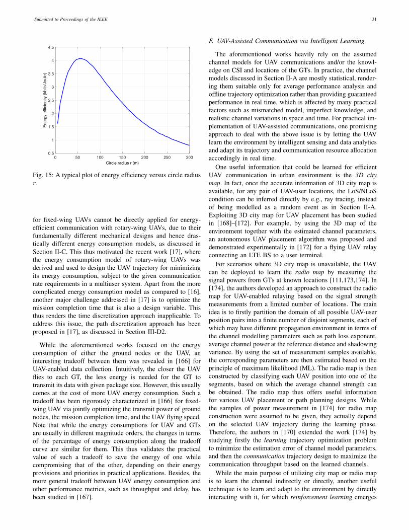
Submitted to Proceedings of the IEEE 31
0 50 100 150 200 250 300
Circle radius r (m)
0.5
1
1.5
2
2.5
3
3.5
4
4.5E
ne
rgy e
ffic
ien
cy (
kb
its/J
ou
le)
Fig. 15: A typical plot of energy efficiency versus circle radiusr.
for fixed-wing UAVs cannot be directly applied for energy-efficient communication with rotary-wing UAVs, due to theirfundamentally different mechanical designs and hence dras-tically different energy consumption models, as discussed inSection II-C. This thus motivated the recent work [17], wherethe energy consumption model of rotary-wing UAVs wasderived and used to design the UAV trajectory for minimizingits energy consumption, subject to the given communicationrate requirements in a multiuser system. Apart from the morecomplicated energy consumption model as compared to [16],another major challenge addressed in [17] is to optimize themission completion time that is also a design variable. Thisthus renders the time discretization approach inapplicable. Toaddress this issue, the path discretization approach has beenproposed in [17], as discussed in Section III-D2.
While the aforementioned works focused on the energyconsumption of either the ground nodes or the UAV, aninteresting tradeoff between them was revealed in [166] forUAV-enabled data collection. Intuitively, the closer the UAVflies to each GT, the less energy is needed for the GT totransmit its data with given package size. However, this usuallycomes at the cost of more UAV energy consumption. Such atradeoff has been rigorously characterized in [166] for fixed-wing UAV via jointly optimizing the transmit power of groundnodes, the mission completion time, and the UAV flying speed.Note that while the energy consumptions for UAV and GTsare usually in different magnitude orders, the changes in termsof the percentage of energy consumption along the tradeoffcurve are similar for them. This thus validates the practicalvalue of such a tradeoff to save the energy of one whilecompromising that of the other, depending on their energyprovisions and priorities in practical applications. Besides, themore general tradeoff between UAV energy consumption andother performance metrics, such as throughput and delay, hasbeen studied in [167].
F. UAV-Assisted Communication via Intelligent Learning
The aforementioned works heavily rely on the assumedchannel models for UAV communications and/or the knowl-edge on CSI and locations of the GTs. In practice, the channelmodels discussed in Section II-A are mostly statistical, render-ing them suitable only for average performance analysis andoffline trajectory optimization rather than providing guaranteedperformance in real time, which is affected by many practicalfactors such as mismatched model, imperfect knowledge, andrealistic channel variations in space and time. For practical im-plementation of UAV-assisted communications, one promisingapproach to deal with the above issue is by letting the UAVlearn the environment by intelligent sensing and data analyticsand adapt its trajectory and communication resource allocationaccordingly in real time.
One useful information that could be learned for efficientUAV communication in urban environment is the 3D citymap. In fact, once the accurate information of 3D city map isavailable, for any pair of UAV-user locations, the LoS/NLoScondition can be inferred directly by e.g., ray tracing, insteadof being modelled as a random event as in Section II-A.Exploiting 3D city map for UAV placement has been studiedin [168]–[172]. For example, by using the 3D map of theenvironment together with the estimated channel parameters,an autonomous UAV placement algorithm was proposed anddemonstrated experimentally in [172] for a flying UAV relayconnecting an LTE BS to a user terminal.
For scenarios where 3D city map is unavailable, the UAVcan be deployed to learn the radio map by measuring thesignal powers from GTs at known locations [111,173,174]. In[174], the authors developed an approach to construct the radiomap for UAV-enabled relaying based on the signal strengthmeasurements from a limited number of locations. The mainidea is to firstly partition the domain of all possible UAV-userposition pairs into a finite number of disjoint segments, each ofwhich may have different propagation environment in terms ofthe channel modelling parameters such as path loss exponent,average channel power at the reference distance and shadowingvariance. By using the set of measurement samples available,the corresponding parameters are then estimated based on theprinciple of maximum likelihood (ML). The radio map is thenconstructed by classifying each UAV position into one of thesegments, based on which the average channel strength canbe obtained. The radio map thus offers useful informationfor various UAV placement or path planning designs. Whilethe samples of power measurement in [174] for radio mapconstruction were assumed to be given, they actually dependon the selected UAV trajectory during the learning phase.Therefore, the authors in [170] extended the work [174] bystudying firstly the learning trajectory optimization problemto minimize the estimation error of channel model parameters,and then the communication trajectory design to maximize thecommunication throughput based on the learned channels.
While the main purpose of utilizing city map or radio mapis to learn the channel indirectly or directly, another usefultechnique is to learn and adapt to the environment by directlyinteracting with it, for which reinforcement learning emerges
Submitted to Proceedings of the IEEE 32
as a powerful tool [175]. Reinforcement learning has been usedin UAV networks for various purposes, e.g., navigation [176],anti-jamming [177], and communication rate maximization[178]. Specifically, the authors in [176] applied the deepreinforcement learning (DRL) technique for autonomous UAVnavigation in complex environment to guide the UAV flyingfrom a given initial location to the destination, using onlysensory information, such as the UAV’s orientation angle andthe distances to obstacles and the destination. While the mainobjective of [176] was to find a feasible path without explicitlyconsidering the communication performance, the authors in[178] studied the trajectory of a UAV BS serving multipleusers to maximize the communication sum rate. By applyingQ-learning, which is a model-free reinforcement learningmethod, the UAV acts as an autonomous agent to learn thetrajectory to maximize the sum rate with multiple groundusers, without assuming any explicit information about theenvironment (such as user locations and channels with them).By dividing the possible flying area into 15 by 15 grids, it wasshown that the UAV is able to interact with the environmentto reach the location achieving the maximum sum rate, andyet avoid flying through the shadowed area with obstacles andthus experiencing poor channel quality. However, as pointedout in [178], one major limitation of the proposed Q-learningapproach for trajectory optimization is the heavy learning time,which makes it infeasible even for moderate state spaces,e.g., 30 by 30 grids. Therefore, one promising future researchdirection is to reduce the complexity and learning time formachine learning based UAV trajectory and communicationco-design. One possible approach is to combine the offlineUAV trajectory designs as described in Section III-D for coarseinitial trajectory planning and the online learning techniquesto further refine the trajectory and optimize communicationresource allocation in real time. Machine learning for UAV-assisted wireless communications is still in its infancy butanticipated to be a promising avenue for future research andinvestigation.
IV. CELLULAR-CONNECTED UAV
In this section, we focus on the other framework of cellular-connected UAV communications, where the UAVs are sup-ported by cellular BSs as new aerial users. We first give ahistorical overview of the past efforts on supporting aerialusers in cellular networks, by highlighting the major fieldtrials from 2G to 4G, including the latest standardizationefforts by 3GPP. We then present some representative workson performance evaluation of cellular-connected UAVs bynumerical simulations as well as theoretical analysis. Last, wediscuss some promising techniques to embrace the new aerialusers in future cellular networks, for air-ground interferencemitigation and QoS-aware UAV trajectory planning.
A. Supporting Aerial Users: Field Trials From 2G to 4G
The attempt to support aerial users with cellular networkscan be traced back to 2000’s via 2G cellular networks,namely Global System for Mobile Communications (GSM)[179]–[181]. A prototype system was developed in [179] to
test the remote UAV operation using General Packet RadioService (GPRS), which is a transmission technology for GSM.Based on the flight test, it was concluded that GSM networkinfrastructures can provide a useful means as a complementarycommunication channel for UAV. In [180], the aerial RSSI(Received Signal Strength Indicator) measurements were con-ducted over GSM networks to show the change of cellularcoverage versus altitude. The results showed that RSSI in-creases with the altitude in urban environment, due to thereduced blockage, whereas it decreases with altitude in ruralenvironment due to the increased link distance. The authorsclaimed that the experiment results provided the evidence ofavailable RF coverage in altitude up to 500 m.
Later, UAV flight tests were conducted over 3G UMTS(Universal Mobile Telecommunications System) network[182]. The measurement results showed good connections forthe UAV altitude up to about 8000 feet (2438 m), beyondwhich the connection was lost. In addition, it was also shownthat although the BS antenna orientations are optimized forground users, the average received power levels of the aerialusers are 21% stronger than those on the ground, with latencyin the order of 500 ms. Based on such results, the authorsconcluded that the 3G UMTS network could provide a possiblesolution for non-safety-critical communications for aerial userswith moderate speed and altitude (below 4000 feet or 1220 m).
While the research work on 2G/3G-supported UAVs waslimited, the enthusiasm for supporting UAVs via the 4G LTEnetwork has skyrocketed during the past few years, in bothacademia (see, e.g., [12,20,23,183]–[187]) and industry. Thiscould be attributed to the significantly enhanced performanceof LTE network over its predecessors, making it more promis-ing to support aerial users, as well as the tremendous increaseof UAV applications over the recent years.
In [183], flight tests with UAV altitude varying from 10 mto 100 m were conducted to compare the latency performanceof cellular-supported UAVs with three different technologies:EDGE (Enhanced Data rates for GSM Evolution, regardedas pre-3G technology), HSPA+ (Evolved High Speed PacketAccess), and 4G LTE. It was revealed that LTE achievedthe best performance in terms of latency and jitter, withround-trip time (RTT) of 127 ms and standard deviationof 48 ms for the worst case scenario, and EDGE had theworst performance. Such results demonstrated the feasibilityof (semi-)autonomous UAV operations over LTE network withlow altitude (say, up to 100 m).
In [188], the possibility of using LTE for controlling multi-copter was studied based on field measurement. The RSRP(Reference Signal Received Power) and RSRQ (ReferenceSignal Received Quality) were measured for an LTE-connectedUAV moving vertically with a maximum altitude at 74 m, andwith a building between the initial UAV location and the BS. Itwas shown that the RSRP firstly increases and then decreaseswith altitude, with the maximum value achieved at around 34m. In contrast, the RSRQ has the trend of decreasing withthe increase of altitude. This is due to that the increase ofinterference is more dominant than the increase of RSRP.
In [20], measurements were taken with the main goalto quantify the interference experienced by aerial users at

Submitted to Proceedings of the IEEE 33
different altitude. It was found that the number of detectableBSs increases as the UAV moves higher. However, the SINRof the best cell for the aerial user at the measured altitude of150 m or 300 m is much lower than that of ground user. This isdue to the dramatic increase of downlink interference at higheraltitude. Such observations have been corroborated by theextensive field trials for UAVs over commercial LTE networksby Qualcom, based on which a trial report on LTE UAS wasreleased in May 2017 [189]. It was found that although theBS antennas are downltilted towards the ground, satisfactorysignal coverage can still be achieved for altitude up to 400 feet(122 m) in the studied test. In fact, the experiment showed thatat 400 feet, the UAV is able to detect 18 BSs with the furthestone up to 11.5 miles (18.5 km) away. Such observations havebeen corroborated by other field measurement campaigns invarious setups [185,186,190]–[192].
B. Recent Results by 3GPP Study
Realizing the great business opportunities for cellular oper-ators with the fast growth of UAV industry, 3GPP approvedthe study item on enhanced LTE support for aerial vehiclesin March 2017 [193]. The main objective of the study itemis to investigate the feasibility and ability of serving aerialvehicles using LTE network with BS antennas downtiltedmainly for terrestrial coverage. The study item was completedin December 2017 with the main results and findings reportedin the Technical Report TR36.777 in Release 15 [5]. It wasthen followed by a new work item aiming to further improvethe efficiency and robustness of terrestrial LTE network forserving UAVs.
In the Technical Report [5] resulted from the study item[193], 3GPP has specified that the maximum height andthe maximum horizontal speed for aerial vehicles are 300m and 160 km/h, respectively. Among others, one of themain outputs from the study item is the comprehensive GBS-UAV channel model for three typical deployment scenarios,as presented in Section II-A. The developed channel modelextends the conventional terrestrial channel model for altitudeup to 300 m, with detailed specifications on the path loss, LoSprobability, shadowing, and small-scale fading. Such a channelmodel is very useful for detailed system level simulationsfor cellular networks with coexisting terrestrial and aerialsuers. Furthermore, based on the extensive field measurementsand system level simulations, 3GPP has identified some maintechnical challenges in supporting aerial vehicles with cellularnetworks. While the detailed findings can be found in [5],we provide a summary of them as follows to motivate futureresearch.
Interference detection: Detecting the interference levelsto/from aerial UEs is necessary for identifying the strong in-terference scenarios and thereby implementing effective coun-termeasures for them, especially when the UEs are potentiallynot certified for aerial usage. Interference detection can beachieved in practice via UE-based solutions and/or network-based solutions. For UE-based solutions, the interference canbe detected based on measurement report by UE, on e.g.,RSRP and RSRQ. Furthermore, other UE-side information
such as mobility history report and speed estimation can beutilized to facilitate the interference detection. On the otherhand, for network-based solutions, interference detection canbe performed by exchanging information among BSs, such astheir uplink scheduling information, and received measurementreports from UEs on their RSRP, RSRQ, and CSI.
Uplink interference mitigation: To mitigate the uplinkinterference caused by the transmission of aerial UEs to theirnon-associated BSs, 3GPP has suggested the following threetechniques:
(i) Uplink power control: To deal with the heterogeneousnetwork with both terrestrial and aerial users, the existinguplink power control mechanism could be improved by e.g.,introducing UE specific power control parameters. For exam-ple, in open loop power control for which the path loss ofUEs is partially compensated, the UE’s transmit power can bewritten as [189]
Ptx = min{Pmax, 10 log10(MRB) + P0 + αUE · TPL},(60)
where Pmax is the maximum transmit power, MRB is thenumber of RBs assigned, P0 is a nominal value, αUE isthe fractional path loss compensation factor, and TPL is theestimated total path loss. The simulation results in [5] showedthat compared to the case where the same αUE is used forall UEs, significant performance gain can be attained by usingheight-dependent compensation factors, e.g., αUE = 0.8 forterrestrial UEs and aerial UEs below 100 m, and αUE = 0.7for aerial UEs above 100 m.
(ii) FD-MIMO: With FD-MIMO (or 3D beamforming), BSsare equipped with full dimensional antenna arrays with activeelements to achieve flexible beamforming in both azimuth andelevation dimensions. FD-MIMO has been supported in LTEsince Release 13, and is particularly promising to supportaerial UEs for interference mitigation, as will be furtherelaborated in Section IV-C.
(iii) Directional antenna at UE: Directional antennas canbe used at aerial UEs to focus the signal downward totheir associated cells while reducing the interference to othercells. Apparently, the performance of this technique criticallydepends on the ability to align the antenna main lobe withthe direction of the serving BS. Depending on the directionalantenna type as discussed in Section II-B, direction alignmentcan be achieved either mechanically or electrically (via phasedarray or digital beamforming).
Downlink interference mitigation: For the mitigation ofdownlink interference from co-channel BSs to aerial UEs,the FD-MIMO and directional antenna at UE can be sim-ilarly applied. In addition, 3GPP has suggested three othertechniques: (i) intra-site joint transmission CoMP (JT CoMP),where multiple cells/sectors belonging to the same site jointlytransmit to their served UEs; (ii) coverage extension tech-niques to enhance synchronization and initial access for aerialUEs. This technique mainly aims to address the extremelysevere interference scenario when even the minimum requiredSINR for the normal LTE control channels cannot be satisfied.The coverage extension introduced in Release 13 is achievedmainly via signal repetitions, which gives higher signal energy
Submitted to Proceedings of the IEEE 34
to mitigate interference through a processing gain [194]; and(iii) coordinated data and control transmission, where data andcontrol signals are jointly transmitted to the UEs.
Mobility: 3GPP has also briefly discussed the potentialenhancement for mobility performance, by e.g., refining han-dover procedure and related parameters for aerial UEs basedon their airborne status, location information, and flying pathinformation, so as to avoid frequent handovers due to highUAV mobility and BS antenna side-lobe gain variation.
As a summary, the extensive field measurement campaignsand 3GPP investigation have provided strong evidence that theexisting LTE networks should be able to support the initialUAV deployment with low density and low altitude, withoutthe need of major changes. On the other hand, they alsorevealed the more severe air-ground interference issue thanthat in the traditional terrestrial network. As the number ofUAVs grow rapidly due to their more appealing applications,it is necessary to develop new techniques to enable cellular-connected UAVs for their larger-scale deployment, in termsof ubiquitous 3D aerial coverage, effective air-ground inter-ference mitigation, as well as enhanced requirements for bothCNPC and payload data communications in anticipation. Inthe following, we present some representative studies on theperformance evaluation of cellular-connected UAVs to gaina deeper understanding of this new cellular system model,followed by some promising and advanced techniques forperformance enhancement.
C. Performance Evaluation
While field tests are very useful for feasibility studies, theyare generally quite expensive and time-consuming to imple-ment. Besides, the obtained results are typically dependenton the particular scenarios being tested. In parallel to thefield tests discussed above, there have been research effortson the performance evaluation of cellular-connected UAVsvia numerical simulations [12,23,195]–[197] or theoreticalanalysis [57,198]–[200].
First, based on the simulation results reported in [12],we illustrate some new considerations that deserve particularattention in designing and implementing cellular-connectedUAV communications. A simplified cellular system with 19sites is considered, each constituting 3 sectors/cells, with theircell IDs labelled in Fig. 16. Two different BS array configu-rations discussed in Section II-B are considered: fixed patternversus 3D beamforming. For fixed pattern, a ULA of size(M1,M2) = (8, 1) is employed at each sector, where M1 andM2 denote the number of antenna elements along the verticaland horizontal dimensions, respectively. For this configuration,the steering magnitude and phase of each antenna elementare predetermined to achieve a −10◦ electrical downtilt. Thesynthesised array radiation pattern of this configuration isshown in Fig. 4. On the other hand, with 3D beamforming,each sector is equipped with a UPA of size (M1,M2) = (8, 4),and the signal magnitude and phase by each antenna elementcan be flexibly designed to enable 3D beamforming.
Fig. 17 shows the empirical cell association probability for auser with three different altitudes, while its horizontal location
is fixed at (250 m, 100 m), as marked in red triangle inFig. 16. The maximum RSRP-based association rule is used. Itis observed from Fig. 17(a) that with the fixed BS pattern, theUAV is most likely associated with the nearby cells when thealtitude is low (e.g., cells 1, 5 and 9 for Hue = 1.5 m and 90m). However, as the altitude increases, it is more likely that theassociated cell is far away from the UAV, e.g., cells 13, 30 and56 for Hue = 200 m. This is expected due to the downtiltedantenna pattern as shown in Fig. 4. Specifically, as the UAVmoves higher, it is likely that it falls into the antenna nulls orweak side lobes of the nearby BSs. As a result, the UAV mayneed to associate with more distant cells via their stronger sidelobes. In contrast, with 3D beamforming, Fig. 17(b) shows thatthe UAV is almost surely associated with the nearby cells evenfor high altitude at Hue = 200 m, thanks to the flexible beamadjustment to focus signals to the UAV with 3D beamforming.
For a cellular network with a total of 15 aerial and groundusers, Fig. 18 plots the empirical cumulative distribution func-tion (CDF) of the users’ achievable sum rate in the downlink asthe number of UAVs changes. It is observed that for both arrayconfigurations, the overall system spectral efficiency degradesas the number of aerial users/UAVs increases. This is mainlydue to the stronger interference suffered by the aerial usersas compared to ground users. On the other hand, Fig. 18shows that by employing 3D beamforming, the system spectralefficiency can be significantly improved. This demonstrates thegreat potential of 3D beamforming for interference mitigationin cellular systems with coexisting aerial and ground users.Similar results and observations can be obtained for theuplink communication with the strong UAV interference toco-channel BSs.
Besides numerical simulations, there were also works ontheoretical performance analysis for cellular-connected UAVs.For example, in [198], based on stochastic geometry with theground BSs modelled by a HPPP, the authors analyzed thedownlink coverage probability for an aerial user coexistingwith conventional ground users. For simplicity, the BS antennawas modelled as the two-lobe model given in (16), while theUAV was assumed to be associated with the nearest BS. Basedon the derived coverage probability expression and numericalexamples, it was concluded that lowering BS antenna heightand increasing downtilt angle is beneficial. However, this resultmay not hold if the RSRP-based association is considered inpractice as it has been shown in Fig. 17 that in general aUAV may not be associated with its nearest BS. Therefore,the analysis in [198] was extended in [57] by associating theUAV with the BS with the maximum power, instead of thenearest one. The authors further extended the analysis to thescenario that the UAV is also equipped with a directionalantenna [199], with the two-lobe antenna model shown in(17). It was found that compared to the case of omnidirec-tional antennas at the UAV, the use of directional antennaswith the optimum choice of antenna tilt can significantlyimprove the coverage probability and achievable throughput.The impact of using directional antenna at UAV for cellularUAV communications has also been studied in [200], wherethe coverage performance was analyzed by assuming that theUAV can intelligently tilt its main lobe direction. A more
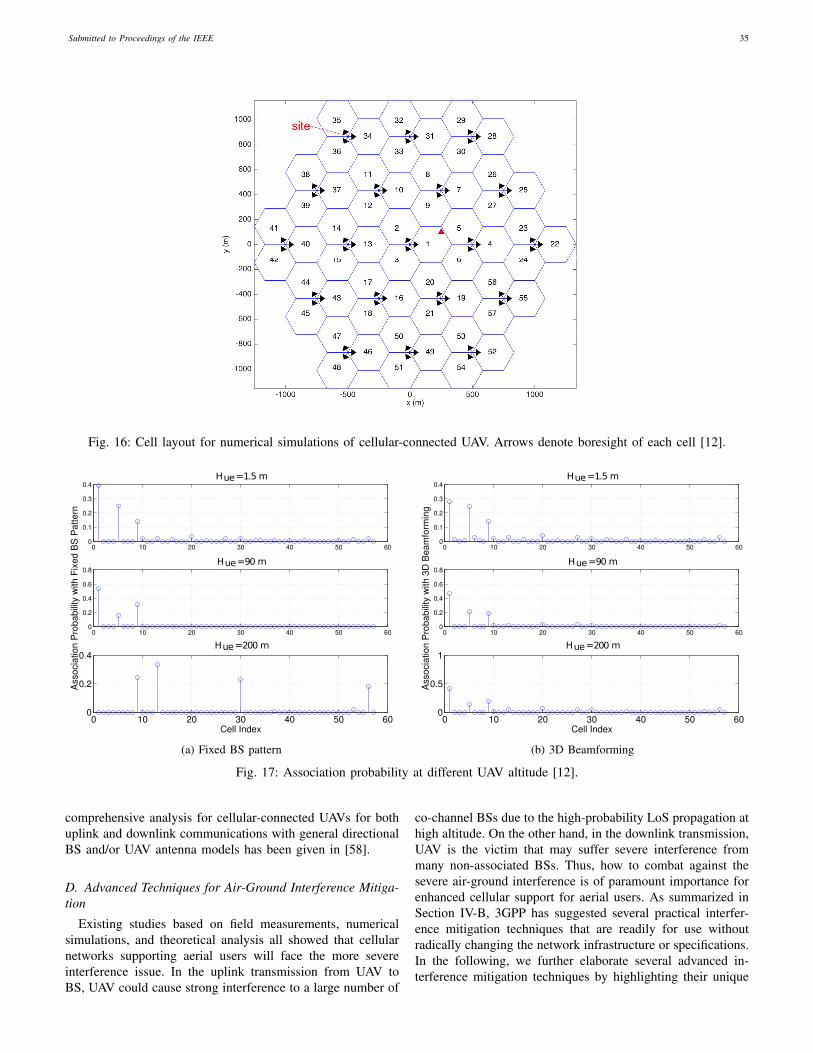
Submitted to Proceedings of the IEEE 35
Fig. 16: Cell layout for numerical simulations of cellular-connected UAV. Arrows denote boresight of each cell [12].
0 10 20 30 40 50 600
0.1
0.2
0.3
0.4Hue=1.5 m
0 10 20 30 40 50 600
0.2
0.4
0.6
0.8Hue=90m
Ass
ocia
tion
Pro
babi
lity
with
Fix
ed B
S P
atte
rn
0 10 20 30 40 50 600
0.2
0.4Hue=200m
Cell Index
(a) Fixed BS pattern
0 10 20 30 40 50 600
0.1
0.2
0.3
0.4Hue=1.5 m
0 10 20 30 40 50 600
0.2
0.4
0.6
0.8Hue=90m
Ass
ocia
tion
Pro
babi
lity
with
3D
Bea
mfo
rmin
g
0 10 20 30 40 50 600
0.5
1Hue=200m
Cell Index
(b) 3D Beamforming
Fig. 17: Association probability at different UAV altitude [12].
comprehensive analysis for cellular-connected UAVs for bothuplink and downlink communications with general directionalBS and/or UAV antenna models has been given in [58].
D. Advanced Techniques for Air-Ground Interference Mitiga-tion
Existing studies based on field measurements, numericalsimulations, and theoretical analysis all showed that cellularnetworks supporting aerial users will face the more severeinterference issue. In the uplink transmission from UAV toBS, UAV could cause strong interference to a large number of
co-channel BSs due to the high-probability LoS propagation athigh altitude. On the other hand, in the downlink transmission,UAV is the victim that may suffer severe interference frommany non-associated BSs. Thus, how to combat against thesevere air-ground interference is of paramount importance forenhanced cellular support for aerial users. As summarized inSection IV-B, 3GPP has suggested several practical interfer-ence mitigation techniques that are readily for use withoutradically changing the network infrastructure or specifications.In the following, we further elaborate several advanced in-terference mitigation techniques by highlighting their unique
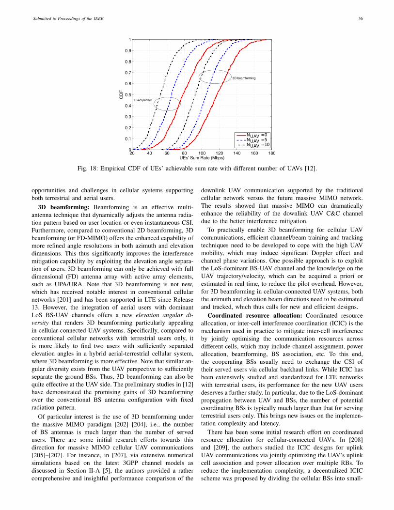
Submitted to Proceedings of the IEEE 36
20 40 60 80 100 120 140 160 1800
0.1
0.2
0.3
0.4
0.5
0.6
0.7
0.8
0.9
1
UEs’ Sum Rate (Mbps)
CD
F
Fixed pattern
3D beamforming
NUAV =0NUAV =5NUAV =10
Fig. 18: Empirical CDF of UEs’ achievable sum rate with different number of UAVs [12].
opportunities and challenges in cellular systems supportingboth terrestrial and aerial users.
3D beamforming: Beamforming is an effective multi-antenna technique that dynamically adjusts the antenna radia-tion pattern based on user location or even instantaneous CSI.Furthermore, compared to conventional 2D beamforming, 3Dbeamforming (or FD-MIMO) offers the enhanced capability ofmore refined angle resolutions in both azimuth and elevationdimensions. This thus significantly improves the interferencemitigation capability by exploiting the elevation angle separa-tion of users. 3D beamforming can only be achieved with fulldimensional (FD) antenna array with active array elements,such as UPA/URA. Note that 3D beamforming is not new,which has received notable interest in conventional cellularnetworks [201] and has been supported in LTE since Release13. However, the integration of aerial users with dominantLoS BS-UAV channels offers a new elevation angular di-versity that renders 3D beamforming particularly appealingin cellular-connected UAV systems. Specifically, compared toconventional cellular networks with terrestrial users only, itis more likely to find two users with sufficiently separatedelevation angles in a hybrid aerial-terrestrial cellular system,where 3D beamforming is more effective. Note that similar an-gular diversity exists from the UAV perspective to sufficientlyseparate the ground BSs. Thus, 3D beamforming can also bequite effective at the UAV side. The preliminary studies in [12]have demonstrated the promising gains of 3D beamformingover the conventional BS antenna configuration with fixedradiation pattern.
Of particular interest is the use of 3D beamforming underthe massive MIMO paradigm [202]–[204], i.e., the numberof BS antennas is much larger than the number of servedusers. There are some initial research efforts towards thisdirection for massive MIMO cellular UAV communications[205]–[207]. For instance, in [207], via extensive numericalsimulations based on the latest 3GPP channel models asdiscussed in Section II-A [5], the authors provided a rathercomprehensive and insightful performance comparison of the
downlink UAV communication supported by the traditionalcellular network versus the future massive MIMO network.The results showed that massive MIMO can dramaticallyenhance the reliability of the downlink UAV C&C channeldue to the better interference mitigation.
To practically enable 3D beamforming for cellular UAVcommunications, efficient channel/beam training and trackingtechniques need to be developed to cope with the high UAVmobility, which may induce significant Doppler effect andchannel phase variations. One possible approach is to exploitthe LoS-dominant BS-UAV channel and the knowledge on theUAV trajectory/velocity, which can be acquired a priori orestimated in real time, to reduce the pilot overhead. However,for 3D beamforming in cellular-connected UAV systems, boththe azimuth and elevation beam directions need to be estimatedand tracked, which thus calls for new and efficient designs.
Coordinated resource allocation: Coordinated resourceallocation, or inter-cell interference coordination (ICIC) is themechanism used in practice to mitigate inter-cell interferenceby jointly optimising the communication resources acrossdifferent cells, which may include channel assignment, powerallocation, beamforming, BS association, etc. To this end,the cooperating BSs usually need to exchange the CSI oftheir served users via cellular backhaul links. While ICIC hasbeen extensively studied and standardized for LTE networkswith terrestrial users, its performance for the new UAV usersdeserves a further study. In particular, due to the LoS-dominantpropagation between UAV and BSs, the number of potentialcoordinating BSs is typically much larger than that for servingterrestrial users only. This brings new issues on the implemen-tation complexity and latency.
There has been some initial research effort on coordinatedresource allocation for cellular-connected UAVs. In [208]and [209], the authors studied the ICIC designs for uplinkUAV communications via jointly optimizing the UAV’s uplinkcell association and power allocation over multiple RBs. Toreduce the implementation complexity, a decentralized ICICscheme was proposed by dividing the cellular BSs into small-

Submitted to Proceedings of the IEEE 37
size clusters, where the information exchange is only neededbetween the UAV and cluster-head BSs by exploiting the LoSmacro-diversity.
CoMP: Compared with coordinated resource allocation,one more effective technique for multi-cell cooperation isCoMP transmission/reception. In this case, the signals foreach user are jointly transmitted/received by multiple coop-erating BSs, which form a virtual distributed antenna arrayor network MIMO system [210]. Different from coordinatedresource allocation aiming to suppress the interfering links,CoMP essentially exploits the strong cross links for desiredsignal transmission by simultaneously associating each userwith multiple BSs. This is especially appealing for cellular-connected UAVs, due to the larger macro-diversity gain avail-able for aerial users as compared to terrestrial users. However,this also incurs more complexity and backhaul transmissiondelay as more cooperating BSs need to be involved. For low-complexity implementation, it is necessary to optimize theset of cooperating BSs so as to achieve a tradeoff betweenperformance and complexity/delay, by taking into account theflying status such as UAV speed and altitude, as well as theBS-UAV channel models. For example, one possible approachis the UAV-oriented cell cooperation, where large-scale multi-cell cooperation is applied for those UAVs with low speed thatinduces slower channel variations, and/or at high altitude withpotentially large macro-diversity gains. In addition, the impactof the additional delay due to CoMP on the performance ofCNPC transmissions needs to be critically evaluated.
There have been some recent research efforts on inves-tigating low-complexity multi-cell cooperation for cellular-connected UAVs. For example, to reduce the backhaul delayof CoMP, the authors in [211] proposed a cooperative inter-ference cancellation strategy for uplink cellular UAV MIMOcommunications. In this scheme, it is assumed that each UAVuses a RB that is occupied by ground users only at some(not all) of the BSs, termed as occupied BSs, which is validin practical cellular networks with fractional frequency reuse.Then those unoccupied BSs could be utilized to decode theUAV signals, and forward them to adjacent occupied BSsfor interference cancellation. The proposed scheme achievesbetter performance than the conventional transmit beamform-ing without the cooperative interference cancellation, and onthe other hand requires less complexity than CoMP sincecooperation is limited only to adjacent BSs.
The above idea was further extended in [212], leading tothe novel scheme termed cooperative NOMA (non-orthogonalmultiple access). Different from the cooperative interferencecancellation between only non-occupied and occupied BSs asin [211], the UAV signal might be also decoded at some of theoccupied BSs, as long as their received UAV signal strengthsare sufficiently strong as compared to that of the terrestrialusers. Then the decoded UAV signal is forwarded to adjacentoccupied BSs for interference cancellation, even without usingthe non-occupied BSs. Compared to the conventional non-cooperative NOMA scheme with only local interference can-cellation at occupied BSs, the proposed cooperative NOMAachieves significant performance gains. The extension of theabove works for UAV downlink communication is more in-
volved, which deserves further studies.
E. QoS-Aware UAV Trajectory Optimization
Different from the conventional terrestrial users that usuallymove sporadically and randomly, the mobility of UAV users isfully or at least partially controllable. This offers an additionalDoF for cellular-connected UAVs, via their communicationQoS-aware trajectory design. For example, for areas whereubiquitous aerial coverage by cellular network has not beenachieved yet, the UAV path can be deliberately planned tocircumvent entering any coverage holes. However, it should benoted that the trajectory design for cellular-connected UAVsis different from that for UAV-assisted communications inthe following aspects. Firstly, for cellular-connected UAVs,UAVs usually have their own missions such as inspection,delivery, photography, etc., which to a certain extent limit theirflexibility in trajectory adaptation to enhance communicationperformance as compared to UAV-assisted communications,in which UAVs are dedicated BSs/relays/APs with fully con-trollably trajectories. Secondly, different from UAV-assistedcommunications where the trajectories of UAV BSs/relays/APsin general need to be designed to ensure the coverage of alltheir served users, for cellular-connected UAVs, they are usersand only need efficient trajectories to fulfill their communica-tion requirements with some BSs along the trajectories. As aresult, the UAV trajectory designs for the above two cases aregenerally different.
As an illustrating example, let’s consider the scenario thata UAV aims to deliver a package from an initial location Ato a destination B with minimum time, while ensuring that itmaintains good connection with at least one BS at any timealong its trajectory. In practice, a good connection may bedefined as follows: the outage probability that the SNR isbelow a target threshold γ is less than some tolerable valueε. Intuitively, for any given ε, the coverage region of eachBS depends on γ, which in turn affects the UAV’s optimalflying path. For simplicity, assuming that the UAV maintainsa constant altitude HU , the coverage areas of the BSs in theUAV’s flying plane for two different γ values are illustrated inFig. 19. Note that the coverage area is in general of irregularshape that depends on the BS antenna radiation pattern andthe random shadowing. When γ is small (i.e., γ = γ1), it ispossible that there exists a straight path from A to B satisfyingthe connectivity constraint with the flying distance minimized,as shown by the red path in Fig. 19. However, as γ increases(i.e., γ = γ2), the UAV may have to detour its flying path tomaintain the connection with BSs, as illustrated by the bluepath in Fig. 19, and as a result, more traveling time is needed.
There have been some recent works along the above direc-tion. For example, in [187], the authors formulated the UAVtrajectory optimization problem to minimize the UAV flyingtime, subject to the stringent zero-outage constraint for theUAV at any time along its trajectory. By assuming the free-space LoS channel model and isotropic antennas so that thecoverage areas in Fig. 19 reduce to circles, effective UAVtrajectory solutions were obtained by utilizing the graph theoryand convex optimization techniques. A similar problem was
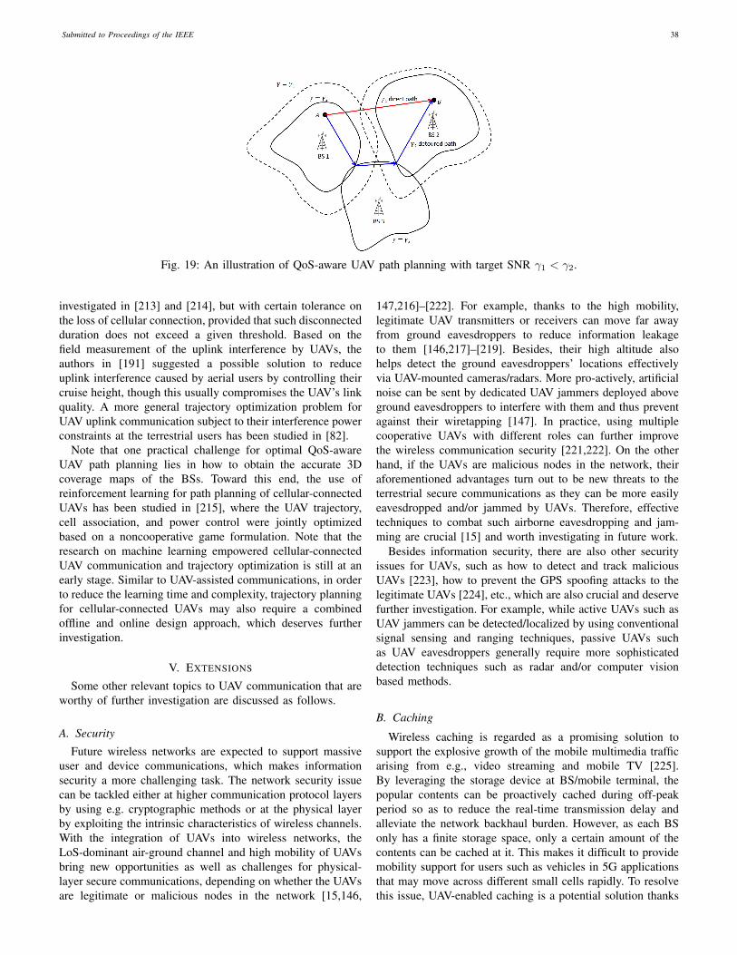
Submitted to Proceedings of the IEEE 38
Fig. 19: An illustration of QoS-aware UAV path planning with target SNR γ1 < γ2.
investigated in [213] and [214], but with certain tolerance onthe loss of cellular connection, provided that such disconnectedduration does not exceed a given threshold. Based on thefield measurement of the uplink interference by UAVs, theauthors in [191] suggested a possible solution to reduceuplink interference caused by aerial users by controlling theircruise height, though this usually compromises the UAV’s linkquality. A more general trajectory optimization problem forUAV uplink communication subject to their interference powerconstraints at the terrestrial users has been studied in [82].
Note that one practical challenge for optimal QoS-awareUAV path planning lies in how to obtain the accurate 3Dcoverage maps of the BSs. Toward this end, the use ofreinforcement learning for path planning of cellular-connectedUAVs has been studied in [215], where the UAV trajectory,cell association, and power control were jointly optimizedbased on a noncooperative game formulation. Note that theresearch on machine learning empowered cellular-connectedUAV communication and trajectory optimization is still at anearly stage. Similar to UAV-assisted communications, in orderto reduce the learning time and complexity, trajectory planningfor cellular-connected UAVs may also require a combinedoffline and online design approach, which deserves furtherinvestigation.
V. EXTENSIONS
Some other relevant topics to UAV communication that areworthy of further investigation are discussed as follows.
A. Security
Future wireless networks are expected to support massiveuser and device communications, which makes informationsecurity a more challenging task. The network security issuecan be tackled either at higher communication protocol layersby using e.g. cryptographic methods or at the physical layerby exploiting the intrinsic characteristics of wireless channels.With the integration of UAVs into wireless networks, theLoS-dominant air-ground channel and high mobility of UAVsbring new opportunities as well as challenges for physical-layer secure communications, depending on whether the UAVsare legitimate or malicious nodes in the network [15,146,
147,216]–[222]. For example, thanks to the high mobility,legitimate UAV transmitters or receivers can move far awayfrom ground eavesdroppers to reduce information leakageto them [146,217]–[219]. Besides, their high altitude alsohelps detect the ground eavesdroppers’ locations effectivelyvia UAV-mounted cameras/radars. More pro-actively, artificialnoise can be sent by dedicated UAV jammers deployed aboveground eavesdroppers to interfere with them and thus preventagainst their wiretapping [147]. In practice, using multiplecooperative UAVs with different roles can further improvethe wireless communication security [221,222]. On the otherhand, if the UAVs are malicious nodes in the network, theiraforementioned advantages turn out to be new threats to theterrestrial secure communications as they can be more easilyeavesdropped and/or jammed by UAVs. Therefore, effectivetechniques to combat such airborne eavesdropping and jam-ming are crucial [15] and worth investigating in future work.
Besides information security, there are also other securityissues for UAVs, such as how to detect and track maliciousUAVs [223], how to prevent the GPS spoofing attacks to thelegitimate UAVs [224], etc., which are also crucial and deservefurther investigation. For example, while active UAVs such asUAV jammers can be detected/localized by using conventionalsignal sensing and ranging techniques, passive UAVs suchas UAV eavesdroppers generally require more sophisticateddetection techniques such as radar and/or computer visionbased methods.
B. Caching
Wireless caching is regarded as a promising solution tosupport the explosive growth of the mobile multimedia trafficarising from e.g., video streaming and mobile TV [225].By leveraging the storage device at BS/mobile terminal, thepopular contents can be proactively cached during off-peakperiod so as to reduce the real-time transmission delay andalleviate the network backhaul burden. However, as each BSonly has a finite storage space, only a certain amount of thecontents can be cached at it. This makes it difficult to providemobility support for users such as vehicles in 5G applicationsthat may move across different small cells rapidly. To resolvethis issue, UAV-enabled caching is a potential solution thanks
Submitted to Proceedings of the IEEE 39
to the UAV’s high mobility [226,227]. Specifically, UAVs candynamically cache the popular contents and track the mobilitypattern of the corresponding users so as to effectively servethem. As compared to caching at fixed terrestrial BSs, theUAV-enabled caching avoids the need of caching the samerequested content at different BSs for serving a moving userand thus greatly saves the storage resource. The results in[228] have shown that such a scheme achieves significantperformance gains in terms of both the average transmit powerand the percentage of the users with satisfied quality-of-experience (QoE) compared with the benchmark case withoutthe use of UAV caching.
However, the performance of the UAV-aided caching systemis practically limited by the endurance of UAVs. To overcomethis issue, [229] proposed a promising solution by jointly ex-ploiting the D2D communications among the ground users andtheir proactive caching. Specifically, a UAV is dispatched toserve a group of ground users with random and asynchronousfile requests and each service period is divided into two phases,i.e., the file caching phase and the file retrieval phase. Inthe first phase, the UAV proactively transmits each file to asubset of selected users that cooperatively cache all the filesof interest during that period, while in the second phase, arequested file by a ground user can be retrieved either fromits own local cache directly or from its nearest neighbor viaD2D communication. As such, the UAV is only needed inthe first phase and the saved time can be used for its batterycharging or conducting other missions.
C. MmWave Communication
By exploiting the enormous chunks of new spectrum avail-able at 30-300 GHz, mmWave communications are expectedto push the mobile data rates to tens of Gbps for supportingemerging rate-demanding applications such as ultra-high defi-nition video (UHDV) streaming and virtual/augmented reality(VR/AR)-based gaming. Although mmWave communicationin general suffers high propagation loss and is vulnerableto blockage, such issues are less severe when mmWave isapplied for UAV communications, thanks to the flexible UAVmobility and favorable air-ground channel characteristics. Forexample, by exploiting the controllable UAV mobility, thecommunication distance can be significantly shortened, whichnot only reduces signal attenuation loss, but also enables highprobability of LoS channels [230,231]. Furthermore, via smartpositioning e.g., adjusting the altitude, the UAV is able tobypass the obstacles such as high-rise buildings and trees thatmay induce blockage in the mmWave UAV communications.Unfortunately, the high UAV mobility and the high operatingcarrier frequency make the Doppler frequency compensationa critical issue for mmWave UAV communications.
Furthermore, although more antennas can be equipped atthe UAV and/or ground node given the same size thanksto the smaller mmWave signal wavelength, the large-arraybeamforming gain is achievable only when efficient chan-nel estimation and tracking can be implemented. The beamtraining with hierarchical beamforming codebooks has beenshown to be an effective technique to achieve this goal [232],
especially for LoS-dominant air-ground channels. However,the existing beam training algorithms are mostly designed forestimating the beam direction in azimuth domain only. Re-cently, a channel tracking method for the flight control system(FCS) was proposed in [233] for UAV communications withmmWave MIMO. Specifically, a 3D geometry-based channelmodel was constructed by combining the UAV movementstate information and the channel gain information, where theformer can be obtained by the sensor fusion of the FCS, whilethe latter can be estimated through the pilot signal. The pro-posed method has been shown to have a much lower trainingoverhead compared to the existing method without utilizingthe UAV movement information. Nevertheless, more researchefforts are still needed to design the efficient channel/beamtraining and tracking techniques catering for 3D mmWave air-ground channels.
D. Mobile Edge Computing
The concept of mobile edge computing (MEC) was mainlymotivated by the emerging new applications such as theVR/AR and autonomous driving, which usually demand ultra-low-latency communication, computation, and control amonga large number of wireless devices. While the real-timecomputation tasks to be executed can be quite intensive,wireless devices are generally of small size and only havelimited computation and data storage resources. As such,MEC has been considered as a key technology for enhancingthe computational capabilities of small devices by allowingthem to offload the computation tasks to nearby MEC servers(e.g., APs and BSs). However, for users located at cell edge,such an offloading strategy may even cause more transmissionenergy and/or longer delay than local computation due to thelimited communication rate with the AP/BS. To address thisproblem, UAVs with highly controllable mobility can be usedas the flying cloudlets to achieve more efficient computationoffloading for the users by moving significantly closer to them[149,234]–[239].
On the other hand, in practice, small UAVs may also havethe need to offload the computation tasks to ground BSs incellular-connected UAVs. By exploiting its LoS dominant linkswith many ground BSs, a UAV user can simultaneously con-nect with multiple GBSs to exploit their distributed computingresources to improve the computation offloading performance[150]. In [150], it has been shown that when the numberof task-input bits is sufficiently large, the UAV should hoverabove its associated GBSs in order to achieve the most efficientcomputation offloading. However, if the UAV’s propulsionenergy consumption is taken into account, this result may nothold, which thus requires further investigation.
E. Wireless Power Transfer
RF transmission enabled wireless power transfer (WPT) isenvisioned as a promising solution to provide perpetual energysupplies for massive low-power devices in the forthcomingIoT networks [240,241]. To compensate the significant signalattenuation over distance, a variety of techniques have been

Submitted to Proceedings of the IEEE 40
proposed to enhance the WPT efficiency, including trans-mit beamforming/precoding, waveform optimization, energyscheduling, etc. However, the efficiency of WPT is still funda-mentally limited by the distances between energy transmitters(ETs) and energy receivers (ERs) [78,79].
To solve this problem, UAV-mounted ETs can be employedto dramatically reduce the link distance by exploiting theirhighly controllable mobility in 3D space [151,242]–[244]. Bymoving close to the ERs with clear LoS links, the UAV-ET cansignificantly improve the efficiency of WPT to ERs, similarlylike in wireless communication. As the energy signals fromthe ET are broadcast to all ERs, the energy harvested at eachER critically depends on the UAV location/trajectory. In [151],it was shown that to maximize the total harvested energy atall ERs, the UAV-ET with one single omnidirectional antennashould hover at one fixed location during the whole chargingperiod. However, this may lead to unfair harvested energyamong ERs due to their different distances from the UAV.To tackle this issue, the problem of maximizing the minimumenergy harvested among all ERs was also considered in [151],where a successive hover-and-fly trajectory was shown tobe optimal. However, how to extend the work [151] to themore general setup with multiple and/or multi-antenna UAV-ETs is still not addressed yet. To enable energy as wellas information transfer, single-antenna UAV-enabled wirelesspowered communication network (WPCN) and simultaneouswireless information and power transfer (SWIPT) system werestudied in [152,243] and [244], respectively, all of whichhave shown that a joint design of the UAV trajectory andenergy/communication scheduling can achieve significant per-formance gains as compared to the case with fixed UAVlocations.
VI. CONCLUSIONS
In this paper, we provide a tutorial on UAV communicationin 5G-and-beyond wireless systems, by addressing its mainchallenges due to the unique communication requirements andchannel characteristics, as well as the new considerations suchas UAV energy limitation, high altitude and high 3D mobility.We first present the fundamental mathematical models usefulfor the performance analysis, evaluation and optimizationof UAV communication, including the channel and antennamodels, UAV energy consumption models, as well as the math-ematical optimization framework for UAV communicationand trajectory co-design. The state-of-the-art results are thenreviewed for the two main research and application paradigmsof UAV communication, namely UAV-assisted terrestrial com-munications and cellular-connected UAVs. We also highlightthe promising directions in UAV communication and otherrelated areas worthy of further investigation in future work. Itis hoped that this paper will be a useful and inspiring resourcefor researchers working in this promising area to unlock thefull potential of wireless communication meeting UAVs.
REFERENCES
[1] FAA, “Summary of small unmanned aircraft rule,”https://www.faa.gov/uas/media/Part 107 Summary.pdf, accessed:Feb. 18, 2019.
[2] “UAS integration pilot program resources.”https://www.faa.gov/uas/programs partnerships/integration pilot program/,accessed: Feb. 18, 2019.
[3] “With 1 announcement, the FAA just created an $82 billion marketand 100,000 new jobs,” https://www.inc.com/yoram-solomon/with-one-rule-the-faa-just-created-an-82-billion-market-and-100000-new-jobs.html, accessed: Feb. 18, 2019.
[4] K. P. Valavanis and G. J. Vachtsevanos, Handbook of unmanned aerialvehicles. Springer Netherlands, 2015.
[5] 3GPP TR 36.777: “Technical specification group radio access network:study on enhanced LTE support for aerial vehicles”, V15.0.0, Dec.,2017.
[6] “China mobile technical report: Internet of drones (in Chinese),” http://www.jintiankansha.me/t/AE9FsWW9tc, accessed: Feb. 18, 2019.
[7] ITU, “Characteristics of unmanned aircraft systems and spectrum re-quirements to support their safe operation in non-segregated airspace,”International Telecommunication Union, Tech. Rep. M.2171, Dec.2009.
[8] R. J. Kerczewski, J. D. Wilson, and W. D. Bishop, “Frequency spectrumfor integration of unmanned aircraft,” in Proc. IEEE/AIAA DigitalAvionics Systems Conference (DASC), Oct. 2013.
[9] C. Carlos, “Spectrum management issues for theoperation of commercial services with UAVs,” avail-able at SSRN: https://ssrn.com/abstract=2944132 orhttp://dx.doi.org/10.2139/ssrn.2944132.
[10] “Launch of inmarsat swiftbroadband unmanned aerial vehicle service toprovide operational capability boost,” https://www.inmarsat.com/press-release/launch-inmarsat-swiftbroadband-unmanned-aerial-vehicle-service-provide-operational-capability-boost/, accessed: Feb. 18,2019.
[11] I. Bekmezci, O. K. Sahingoz, and S. Temel, “Flying ad-hoc networks(FANETs): a survey,” Ad Hoc Networks, vol. 11, no. 3, pp. 1254–1270,Jan. 2013.
[12] Y. Zeng, J. Lyu, and R. Zhang, “Cellular-connected UAV: potentials,challenges and promising technologies,” IEEE Wireless Commun.,vol. 26, no. 1, pp. 120–127, Feb. 2019.
[13] Y. Zeng, R. Zhang, and T. J. Lim, “Wireless communications with un-manned aerial vehicles: opportunities and challenges,” IEEE Commun.Mag., vol. 54, no. 5, pp. 36–42, May 2016.
[14] “Paving the path to 5G: optimizing commercial LTE networks for dronecommunication.” https://www.qualcomm.com/news/onq/2016/09/06/paving-path-5g-optimizing-commercial-lte-networks-drone-communication,accessed: Feb. 18, 2019.
[15] Q. Wu, W. Mei, and R. Zhang, “Safeguarding wireless networkwith UAVs: a physical layer security perspective,” arXiv preprintarXiv:1902.02472, 2019.
[16] Y. Zeng and R. Zhang, “Energy-efficient UAV communication withtrajectory optimization,” IEEE Trans. Wireless Commun., vol. 16, no. 6,pp. 3747–3760, Jun. 2017.
[17] Y. Zeng, J. Xu, and R. Zhang, “Energy minimization for wirelesscommunication with rotary-wing UAV,” to appear in IEEE Trans.Wireless Commun., arXiv preprint arXiv:1804.02238, 2018.
[18] Y. Chen, S. Zhang, S. Xu, and G. Y. Li, “Fundamental trade-offs ongreen wireless networks,” IEEE Commun. Mag., vol. 49, no. 6, pp.30–37, Jun. 2011.
[19] Z. Hasan, H. Boostanimehr, and V. K. Bhargava, “Green cellular net-works: a survey, some research issues and challenges,” IEEE Commun.Surveys Tuts., vol. 13, no. 4, pp. 524–540, Fourth quarter 2011.
[20] B. V. D. Bergh, A. Chiumento, and S. Pollin, “LTE in the sky: tradingoff propagation benefits with interference costs for aerial nodes,” IEEECommun. Mag., vol. 54, no. 5, pp. 44–50, May 2016.
[21] I. B. Yaliniz and H. Yanikomeroglu, “The new frontier in RANheterogeneity: multi-tier drone-cells,” IEEE Commun. Mag., vol. 54,no. 11, pp. 48–55, Nov. 2016.
[22] S. Sekander, H. Tabassum, and E. Hossain, “Multi-tier drone architec-ture for 5G/B5G cellular networks: challenges, trends, and prospects,”IEEE Commun. Mag., vol. 56, no. 3, pp. 96–103, Mar. 2018.
[23] X. Lin, et al., “The sky is not the limit: LTE for unmanned aerialvehicles,” IEEE Commun. Mag., vol. 56, no. 4, pp. 204–210, Apr.2018.
[24] W. Khawaja, I. Guvenc, D. Matolak, U.-C. Fiebig, and N. Schnecken-berger, “A survey of air-to-ground propagation channel modeling forunmanned aerial vehicles,” arXiv preprint arXiv:1801.01656, 2018.
[25] D. W. Matolak and R. Sun, “Unmanned aircraft systems: air-groundchannel characterization for future applications,” IEEE Veh. Technol.Mag., vol. 10, no. 2, pp. 79–85, Jun. 2015.
Submitted to Proceedings of the IEEE 41
[26] A. A. Khuwaja, Y. Chen, N. Zhao, M.-S. Alouini, and P. Dobbins, “Asurvey of channel modeling for UAV communications,” arXiv preprintarXiv:1801.07359, 2018.
[27] E. W. Frew and T. X. Brown, “Airborne communication networks forsmall unmanned aircraft systems,” Proceedings of the IEEE, vol. 96,no. 12, pp. 2008–2027, Dec. 2008.
[28] L. Gupta, R. Jain, and G. Vaszkun, “Survey of important issues in UAVcommunication networks,” IEEE Commun. Surveys Tuts., vol. 18, no. 2,pp. 1123–1152, Second quarter 2016.
[29] S. Hayat, E. Yanmaz, and R. Muzaffar, “Survey on unmanned aerialvehicle networks for civil applications: a communications viewpoint,”IEEE Commun. Surveys Tuts.,, vol. 18, no. 4, pp. 2624–2661, Fourthquarter 2016.
[30] H. Shakhatreh, A. Sawalmeh, A. Al-Fuqaha, Z. Dou, E. Almaita,I. Khalil, N. S. Othman, A. Khreishah, and M. Guizani, “Unmannedaerial vehicles: a survey on civil applications and key research chal-lenges,” arXiv preprint arXiv:1805.00881, 2018.
[31] N. H. Motlagh, T. Taleb, and O. Arouk, “Low-altitude unmanned aerialvehicles-based internet of things services: comprehensive survey andfuture perspectives,” IEEE Internet of Things Journal, vol. 3, no. 6, pp.899–922, Dec. 2016.
[32] R. Shakeri, M. A. Al-Garadi, A. Badawy, A. Mohamed, T. Khattab,A. Al-Ali, K. A. Harras, and M. Guizani, “Design challenges of multi-UAV systems in cyber-physical applications: a comprehensive survey,and future directions,” arXiv preprint arXiv:1810.09729, 2018.
[33] M. Mozaffari, W. Saad, M. Bennis, Y.-H. Nam, and M. Debbah, “Atutorial on UAVs for wireless networks: applications, challenges, andopen problems,” arXiv preprint arXiv:1803.00680, 2018.
[34] A. Fotouhi, H. Qiang, M. Ding, M. Hassan, L. G. Giordano, A. Garcia-Rodriguez, and J. Yuan, “Survey on UAV cellular communications:practical aspects, standardization advancements, regulation, and secu-rity challenges,” arXiv preprint arXiv:1809.01752, 2018.
[35] N. Goddemeier, K. Daniel, and C. Wietfeld, “Role-based connectiv-ity management with realistic air-to-ground channels for cooperativeUAVs,” IEEE J. Sel. Areas Commun., vol. 30, no. 5, pp. 951–963, Jun.2012.
[36] N. Ahmed, S. S. Kanhere, and S. Jha, “On the importance of linkcharacterization for aerial wireless sensor networks,” IEEE Commun.Mag., pp. 52–57, May 2016.
[37] A. Goldsmith, Wireless Communications. Cambridge University Press,2005.
[38] Y. Zeng, R. Zhang, and T. J. Lim, “Throughput maximization for UAV-enabled mobile relaying systems,” IEEE Trans. Commun., vol. 64,no. 12, pp. 4983–4996, Dec. 2016.
[39] Q. Wu, Y. Zeng, and R. Zhang, “Joint trajectory and communicationdesign for multi-UAV enabled wireless networks,” IEEE Trans. Wire-less Commun., vol. 17, no. 3, pp. 2109–2121, Mar. 2018.
[40] R. Amorim, H. C. Nguyen, P. E. Mogensen, I. Z. Kovacs, J. Wigard,and T. B. Sorensen, “Radio channel modeling for UAV communicationover cellular networks,” IEEE Wireless Commun. Lett., vol. 6, no. 4,pp. 514–517, Aug. 2017.
[41] M. M. Azari, F. Rosas, K.-C. Chen, and S. Pollin, “Ultra reliable UAVcommunication using altitude and cooperation diversity,” IEEE Trans.Commun., vol. 66, no. 1, pp. 330–344, Jan. 2018.
[42] A. Al-Hourani and K. Gomez, “Modeling cellular-to-UAV path-loss forsuburban environments,” IEEE Wireless Commun. Lett., vol. 7, no. 1,pp. 82–85, Feb. 2018.
[43] Q. Feng, E. K. Tameh, A. R. Nix, and J. McGeehan, “Modelling thelikelihood of line-of-sight for air-to-ground radio propagation in urbanenvironments,” in Proc. IEEE Global Communications Conference(GLOBECOM), Nov. 2006.
[44] Q. Feng, J. McGeehan, E. K. Tameh, and A. R. Nix, “Path loss modelsfor air-to-ground radio channels in urban environments,” in Proc. IEEEVehicular Technology Conference (VTC), May 2006.
[45] A. A. Hourani, S. Kandeepan, and A. Jamalipour, “Modeling air-to-ground path loss for low altitude platforms in urban environments,” inProc. IEEE Global Communications Conference (GLOBECOM), Dec.2014.
[46] A. Al-Hourani, S. Kandeepan, and S. Lardner, “Optimal LAP altitudefor maximum coverage,” vol. 3, no. 6, pp. 569–572, Dec. 2014.
[47] Recommendation ITU-R P.1410-5, “Propagation data and predictionmethods required for the design of terrestrial broadband radio ac-cess systems operating in a frequency range from 3 to 60 GHz,”https://www.itu.int/rec/R-REC-P.1410/en, accessed: Feb. 18, 2019.
[48] M. Mozaffari, W. Saad, M. Bennis, and M. Debbah, “Unmanned aerialvehicle with underlaid device-to-device communications: performance
and tradeoffs,” IEEE Trans. Wireless Commun., vol. 15, no. 6, pp.3949–3963, Jun. 2016.
[49] 3GPP TR 38.901: “Study on channel model for frequencies from 0.5to 100 GHz”, V14.0.0.
[50] L. Zeng, X. Cheng, C.-X. Wang, and X. Yin, “A 3D geometry-basedstochastic channel model for UAV-MIMO channels,” in Proc. IEEEWireless Commun. Net. Conf. (WCNC), Mar. 2017.
[51] D. W. Matolak and R. Sun, “Air-gound channel characterization forunmanned aircraft systems–Part I: methods, measurements, and modelsfor over-water settings,” IEEE Trans. Veh. Tech., vol. 66, no. 1, pp. 26–44, Jan. 2017.
[52] ——, “Air-ground channel characterization for unmanned aircraftsystems–Part III: the suburban and near-urban environments,” IEEETrans. Veh. Tech., vol. 66, no. 8, pp. 6607–6618, Aug. 2017.
[53] R. Sun and D. W. Matolak, “Air-ground channel characterization forunmanned aircraft systems–Part II: hilly & mountainous settings,”IEEE Trans. Veh. Tech., vol. 66, no. 3, pp. 1913–1925, Mar. 2017.
[54] W. Khawaja, O. Ozdemir, and I. Guvenc, “UAV air-to-ground chan-nel characterization for mmWave systems,” in Proc. IEEE VehicularTechnology Conference (VTC), Sep. 2017.
[55] 3GPP TR 36.873: “Study on 3D channel model for LTE”, V12.7.0,Dec., 2017.
[56] M. C. V. K. Venugopal and R. W. Heath, “Device-to-device millimeterwave communications: Interference, coverage, rate, and finite topolo-gies,” IEEE Trans. Wireless Commun., vol. 15, no. 9, pp. 6175–6188,Sep. 2016.
[57] M. M. Azari, F. Rosas, A. Chiumento, and S. Pollin, “Reshapingcellular networks for the sky: the major factors and feasibility,” inProc. IEEE International Conference on Communications (ICC), May2018.
[58] J. Lyu and R. Zhang, “Network-connected UAV: 3D system modelingand coverage performance analysis,” submitted to IEEE Internet ofThings Journal, arXiv preprint arXiv:1901.07887, 2019.
[59] H. He, S. Zhang, Y. Zeng, and R. Zhang, “Joint altitude and beamwidthoptimization for UAV-enabled multiuser communications,” IEEE Com-mun. Lett., vol. 22, no. 2, pp. 344–347, Feb. 2018.
[60] M. Mozaffari, W. Saad, M. Bennis, and M. Debbah, “Efficient de-ployment of multiple unmanned aerial vehicles for optimal wirelesscoverage,” IEEE Commun. Lett., vol. 20, no. 8, pp. 1647–1650, Aug.2016.
[61] B. Galkin, J. Kibiłda, and L. A. DaSilva, “A stochastic model for UAVnetworks positioned above demand hotspots in urban environments,”arXiv preprint arXiv:1804.11001, 2018.
[62] 3GPP TR 36.897: “Technical specification group radio access network:study on elevation beamforming/full-dimension (FD) Multiple InputMultiple Output (MIMO) for LTE”, V13.0.0, Jun. 2015.
[63] Y. Zeng and R. Zhang, “Cost-effective millimeter wave communica-tions with lens antenna array,” IEEE Wireless Commun., vol. 24, no. 4,pp. 81–87, Aug. 2017.
[64] S. Hur, et al., “Millimeter wave beamforming for wireless backhauland access in small cell networks,” IEEE Trans. Commun., vol. 61,no. 10, pp. 4391–4403, Oct. 2013.
[65] X. Zhang, A. F. Molish, and S. Y. Kung, “Variable-phase-shift-basedRF-baseband codesign for MIMO antenna selection,” IEEE Trans.Signal Process., vol. 53, no. 11, pp. 4091–4103, Nov. 2005.
[66] O. E. Ayach, S. Rajagopal, S. Abu-Surra, Z. Pi, and R. W. Heath Jr,“Spatially sparse precoding in millimeter wave MIMO systems,” IEEETrans. Wireless Commun., vol. 13, no. 3, pp. 1499–1513, Mar. 2013.
[67] Y. Zeng and R. Zhang, “Millimeter wave MIMO with lens antennaarray: a new path division multiplexing paradigm,” IEEE Trans. Com-mun., vol. 64, no. 4, pp. 1557–1571, Apr. 2016.
[68] Y. Zeng, L. Yang, and R. Zhang, “Multi-user millimeter wave MIMOwith full-dimensional lens antenna array,” IEEE Trans. Wireless Com-mun., vol. 17, no. 4, pp. 2800–2814, Apr. 2018.
[69] C. D. Franco and G. Buttazzo, “Energy-aware coverage path planningof UAVs,” in Proc. IEEE International Conference on AutonomousRobot Systems and Competitions, Apr. 2015.
[70] A. Richards and J. P. How, “Aircraft trajectory planning with collisionavoidance using mixed integer linear programming,” in Proc. IEEEAmerican Control Conference, May 2002.
[71] C. S. Ma and R. H. Miller, “MILP optimal path planning for real-timeapplications,” in Proc. IEEE American Control Conference, Jun. 2006.
[72] E. I. Grotli and T. A. Johansen, “Path planning for UAVs undercommunication constraints using SPLAT! and MILP,” J. Intell. RobotSyst, vol. 65, pp. 265–282, 2012.

Submitted to Proceedings of the IEEE 42
[73] Y. Mei, Y.-H. Lu, Y. C. Hu, and C. S. G. Lee, “Energy-efficient motionplanning for mobile robots,” in Proc. IEEE International Conferenceon Robotics and Automation, Apr. 2004.
[74] Y. Zeng, X. Xu, and R. Zhang, “Trajectory design for completiontime minimization in UAV-enabled multicasting,” IEEE Trans. WirelessCommun., vol. 17, no. 4, pp. 2233–2246, Apr. 2018.
[75] M. Mozaffari, W. Saad, M. Bennis, and M. Debbah, “Wireless com-munication using unmanned aerial vehicles (UAVs): optimal transporttheory for hover time optimization,” IEEE Trans. Wireless Commun.,vol. 16, no. 12, pp. 8052–8066, Dec. 2017.
[76] J. Gong, T.-H. Chang, C. Shen, and X. Chen, “Flight time minimizationof UAV for data collection over wireless sensor networks,” IEEE J. Sel.Areas Commun., vol. 36, no. 9, pp. 1942–1954, Sep. 2018.
[77] S. Zhang, Q. Wu, S. Xu, and G. Y. Li, “Fundamental green tradeoffs:progresses, challenges, and impacts on 5G networks,” IEEE Commun.Surveys Tuts., vol. 19, no. 1, pp. 33–56, First Quarter 2017.
[78] Q. Wu, G. Y. Li, W. Chen, D. W. K. Ng, and R. Schober, “An overviewof sustainable green 5G networks,” IEEE Wireless Commun., vol. 24,no. 4, pp. 72–80, Aug. 2017.
[79] Q. Wu, M. Tao, D. W. K. Ng, W. Chen, and R. Schober, “Energy-efficient resource allocation for wireless powered communication net-works,” IEEE Trans. Wireless Commun., vol. 15, no. 3, pp. 2312–2327,Mar. 2016.
[80] Q. Wu, Y. Zeng, and R. Zhang, “Joint trajectory and communicationdesign for UAV-enabled multiple access,” in Proc. IEEE GlobalCommunications Conference (GLOBECOM), Dec. 2017.
[81] C. You and R. Zhang, “3D trajectory optimization in Rician fadingfor UAV-enabled data harvesting,” submitted to IEEE Trans. WirelessCommun., arXiv preprint arXiv:1901.04106, 2019.
[82] Y. Huang, W. Mei, J. Xu, L. Qiu, and R. Zhang, “Cognitive UAVcommunication via joint maneuver and power control,” submitted toIEEE Trans. Commun., arXiv preprint arXiv: 1901.02804, 2019.
[83] S. Rohde, M. Putzke, and C. Wietfeld, “Ad-hoc self-healing ofOFDMA networks using UAV-based relays,” Ad Hoc Networks, vol. 11,no. 7, pp. 1893–1906, Sep. 2013.
[84] V. Sharma, K. Srinivasan, H.-C. Chao, K.-L. Hua, and W.-H. Cheng,“Intelligent deployment of UAVs in 5G heterogeneous communicationenvironment for improved coverage,” Journal of Network and Com-puter Applications, vol. 85, pp. 94–105, May 2016.
[85] D. Orfanus, E. P. Freitas, and F. Eliassen, “Self-organization as asupporting paradigm for military UAV relay networks,” IEEE Commun.Lett., vol. 20, no. 4, pp. 804–807, Apr. 2016.
[86] J. Zhang, Y. Zeng, and R. Zhang, “UAV-enabled radio access network:multi-mode communication and trajectory design,” IEEE Trans. SignalProcess., vol. 66, no. 20, pp. 5269–5284, Oct. 2018.
[87] W. Guo, C. Devine, and S. Wang, “Performance analysis of microunmanned airborne communication relays for cellular networks,” inProc. IEEE Int. Symp. Commun. Syst., Netw., Digital Signal (CSNDSP),Jul. 2014, pp. 658–663.
[88] R. T. R. L. Gomez, K. and S. Kandeepan, “On the performance ofaerial LTE base-stations for public safety and emergency recovery,” inProc. IEEE Global Communications Conference (GLOBECOM), Dec.2013.
[89] K. Gomez, A. Hourani, L. Goratti, R. Riggio, S. Kandeepan, and I. Bu-caille, “Capacity evaluation of aerial LTE base-stations for public safetycommunications,” in Proc. IEEE European Conference on Networksand Communications, Jun. 2015.
[90] A. Al-Hourani, S. Chandrasekharan, G. Kaandorp, W. Glenn, A.Jamalipour, and S. Kandeepan, “Coverage and rate analysis of aerialbase stations,” IEEE Trans. Aerospace and Elect. Sys., vol. 52, no. 6,pp. 3077–3081, Dec. 2016.
[91] M. M. Azari, F. Rosas, K.-C. Chen, A. Chiumento, and S. Pollin, “Jointsum-rate and power gain analysis of an aerial base station,” in Proc.IEEE Global Communications Conference (GLOBECOM), Dec. 2016.
[92] M. M. Azari, F. Rosas, A. Chiumento, K.-C. Chen, and S. Pollin,“Coverage and power gain of aerial versus terrestrial base stations,”in Advances in Ubiquitous Networking. Singapore: Springer, pp. 627–636, 2017.
[93] K. Han, K. Huang, and R. W. Heath, “Connectivity and blockageeffects in millimeter-wave air-to-everything networks,” arXiv preprintarxiv:1808.00144, 2018.
[94] A. M. Hayajneh, S. A. R. Zaidi, D. C. McLernon, and M. Ghogho,“Drone empowered small cellular disaster recovery networks for re-silient smart cities,” in Proc. IEEE Int. Conf. Sensing, Communicationand Networking (SECON Workshops), Jun. 2016.
[95] V. V. Chetlur and H. S. Dhillon, “Downlink coverage analysis for afinite 3-D wireless network of unmanned aerial vehicles,” IEEE Trans.Commun., vol. 65, no. 10, pp. 4543–4558, Oct. 2017.
[96] M. Mahdi Azari, Y. Murillo1, O. Amin, F. Rosas, M. S. Alouini, S.Pollin, “Coverage maximization for a Poisson field of drone cells,”arXiv preprint arXiv:1708.06598, 2017.
[97] B. Galkin, J. Kibilda, and L. A. DaSilva, “Coverage analysis forlow-altitude UAV networks in urban environments,” in IEEE GlobalCommunications Conference (GLOBECOM), 2017.
[98] C. Zhang and W. Zhang, “Spectrum sharing for drone networks,” IEEEJ. Sel. Areas Commun., vol. 35, no. 1, pp. 136–144, Jan. 2017.
[99] C. Liu, M. Ding, C. Ma, Q. Li, Z. Lin, and Y.-C. Liang, “Perfor-mance analysis for practical unmanned aerial vehicle networks withLoS/NLoS transmissions,” in Proc. IEEE International Conference onCommunications (ICC), May 2018.
[100] F. Ono, H. Ochiai, and R. Miura, “A wireless relay network based onunmanned aircraft system with rate optimization,” IEEE Trans. WirelessCommun., vol. 15, no. 11, pp. 7699–7708, Nov. 2016.
[101] J. Lyu, Y. Zeng, and R. Zhang, “Cyclical multiple access in UAV-aided communications: a throughput-delay tradeoff,” IEEE WirelessCommun. Lett., vol. 5, no. 6, pp. 600–603, Dec. 2016.
[102] S. Enayati, H. Saeedi, H. Pishro-Nik, and H. Yanikomeroglu, “Movingaerial base station networks: stochastic geometry analysis and designperspective,” http://www.ecs.umass.edu/ece/pishro/Papers/ABS.pdf.
[103] F. Ono et al., “Measurement of TCP and UDP performance over UASrelay networks,” in Proc. IEEE International Conference on UnmannedAircraft Systems (ICUAS), May 2014.
[104] Z. M. Fadlullah, D. Takaishi, H. Nishiyama, N. Kato, and R. Miura, “Adynamic trajectory control algorithm for improving the communicationthroughput and delay in UAV-aided networks,” IEEE Network, vol. 30,no. 1, pp. 100–105, Jan. 2016.
[105] Z. Becvar, M. Vondra, P. Mach, J. Plachy, and D. Gesbert, “Per-formance of mobile networks with UAVs: can flying base stationssubstitute ultra-dense small cells?” in Proc. IEEE European WirelessConf., May 2017.
[106] J. Lyu, Y. Zeng, R. Zhang, “UAV-aided offloading for cellular hotspot,”IEEE Trans. Wireless Commun., vol. 17, no. 6, pp. 3988–4001, Jun.2018.
[107] R. Yaliniz, A. El-Keyi, and H. Yanikomeroglu, “Efficient 3-D place-ment of an aerial base station in next generation cellular networks,” inProc. IEEE International Conference on Communications (ICC), May2016.
[108] M. Alzenad, A. El-keyi, F. Lagum, and H. Yanikomeroglu, “3Dplacement of an unmanned aerial vehicle base station (UAV-BS) forenergy-efficient maximal coverage,” IEEE Wireless Commun. Lett.,vol. 6, no. 4, pp. 434–437, Aug. 2017.
[109] M. Alzenad, A. El-Keyi, and H. Yanikomeroglu, “3D placement of anunmanned aerial vehicle base station for maximum coverage of userswith different QoS requirements,” IEEE Wireless Commun. Letters,vol. 7, no. 1, pp. 38–41, Feb. 2018.
[110] E. Kalantari, M. Z. Shakir, H. Yanikomeroglu, and A. Yongacoglu,“Backhaul-aware robust 3D drone placement in 5G+ wireless net-works,” in Proc. IEEE International Conference on Communications(ICC), May 2017.
[111] J. Chen and D. Gesbert, “Optimal positioning of flying relays forwireless networks: a LOS map approach,” in Proc. IEEE InternationalConference on Communications (ICC), May 2017.
[112] E. Kalantari, H. Yanikomeroglu, and A. Yongacoglu, “On the numberand 3D placement of drone base stations in wireless cellular networks,”in Proc. IEEE Vehicular Technology Conference (VTC), Sep. 2016.
[113] J. Lyu, Y. Zeng, R. Zhang, and T. J. Lim, “Placement optimizationof UAV-mounted mobile base stations,” IEEE Commun. Lett., vol. 21,no. 3, pp. 604–607, Mar. 2017.
[114] X. He, W. Yu, H. Xu, J. Lin, X. Yang, C. Lu, and X. Fu, “Towards3D deployment of UAV base stations in uneven terrain,” in Proc. IEEEInternational Conference on Computer Communication and Networks(ICCCN), Aug. 2018.
[115] M. Mozaffari, W. Saad, M. Bennis, and M. Debbah, “Drone small cellsin the clouds: Design, deployment and performance analysis,” in Proc.IEEE Global Communications Conference (GLOBECOM), Dec. 2015.
[116] Z. Wang, L. Duan, and R. Zhang, “Adaptive deployment for UAV-aidedcommunication networks,” arXiv preprint arXiv:1812.03267, 2018.
[117] M. Grossglauser and D. N. C. Tse, “Mobility increases the capacityof ad hoc wireless networks,” IEEE/ACM Trans. Networking, vol. 10,no. 4, pp. 477–486, Aug. 2002.
Submitted to Proceedings of the IEEE 43
[118] Y. Yan and Y. Mostofi, “Co-optimization of communication and motionplanning of a robotic operation under resource constraints and in fadingenvironments,” IEEE Trans. Wireless Commun., vol. 12, no. 4, pp.1562–1572, Apr. 2013.
[119] T. Schouwenaars, B. D. Moor, E. Feron, and J. How, “Mixed integerprogramming for multi-vehicle path planning,” in Proc. IEEE EuropeanControl Conference, Sep. 2001.
[120] I. K. Nikolos, N. C. Tsourveloudis, and K. P. Valavanis, “Evolutionaryalgorithm based offline/online path planner for UAV navigation,” IEEETrans. Syst. Man Cybern., Part B, Cybern., vol. 33, no. 6, pp. 898–912,Dec. 2003.
[121] C. Zheng, L. Li, F. Xu, F. Sun, and M. Ding, “Evolutionary routeplanner for unmanned air vehicles,” IEEE Trans. Robotics, vol. 21,no. 4, pp. 609–620, Aug. 2005.
[122] J. Bellingham, A. Richards, and J. P. How, “Receding horizon controlof autonomous aerial vehicles,” in Proc. IEEE American ControlConference, May 2002.
[123] T. Schouwenaars, A. Stubbs, J. Paduano, and E. Feron, “Multi-vehiclepath planning for non-line of sight communication,” Journal of FieldRobotics, pp. 269–290, Jul. 2006.
[124] P. Zhan, K. Yu, and A. L. Swindlehurst, “Wireless relay communica-tions with unmanned aerial vehicles: performance and optimization,”IEEE Trans. Aerospace and Electronic Systems, vol. 47, no. 3, pp.2068–2085, Jul. 2011.
[125] F. Jiang and A. L. Swindlehurst, “Optimization of UAV heading forthe ground-to-air uplink,” IEEE J. Sel. Areas Commun., vol. 30, no. 5,pp. 993–1005, Jun. 2012.
[126] K. Anazawa, P. Li, T. Miyazaki, and S. Guo, “Trajectory and dataplanning for mobile relay to enable efficient Internet access after dis-asters,” in IEEE Global Communications Conference (GLOBECOM),Dec. 2015.
[127] Z. Han, A. L. Swindlehurst, and K. J. R. Liu, “Optimization ofMANET connectivity via smart deployment/movement of unmannedair vehicles,” IEEE Trans. Veh. Technol., vol. 58, no. 7, pp. 3533–3546,Sep. 2009.
[128] S. Kim, H. Oh, J. Suk, and A. Tsourdos, “Coordinated trajectoryplanning for efficient communication relay using multiple UAVs,” inCont. Eng. Pract. (ELSEVIER), vol. 29, pp. 42–49, May 2014.
[129] E. L. Lawler, J. K. Lenstra, A. H. G. R. Kan, and D. B. Shmoys,The Traveling Salesman Problem: A Guided Tour of CombinatorialOptimization, 1st ed. Wiley, 1985.
[130] G. Laporte, “The traveling salesman problem: an overview of exactand approximate algorithms,” EUR. J. Oper. Res., vol. 59, no. 2, pp.231–247, Jun. 1992.
[131] “Travelling Salesman Problem: Solver-Based”.Accessed: Jan. 11, 2018. [Online]. Availablehttps://www.mathworks.com/help/optim/ug/travelling-salesman-problem.html, accessed on Feb. 18, 2019.
[132] C. Rego, D. Gamboa, F. Glover, and C. Osterman, “Traveling sales-man problem heuristics: leading methods, implementations and latestadvances,” European Journal of Operational Research, vol. 211, no. 3,pp. 427–441, 2011.
[133] A. Dumitrscu and J. Mitchell, “Approximation algorithms for TSP withneighborhoods in the plane,” J. Algorithms, vol. 48, no. 1, pp. 135–159,2003.
[134] B. Yuan, M. Orlowska, and S. Sadiq, “On the optimal robot routingproblem in wireless sensor networks,” IEEE Trans. Knowledge andData Eng., vol. 19, no. 9, pp. 1252–1261, Sep. 2007.
[135] G. Laporte and S. Martello, “The selective travelling salesman prob-lem,” Discrete Applied Mathematics, vol. 26, no. 2–3, pp. 193–207,Mar. 1990.
[136] P. Vansteenwegen, W. Souffriau, and D. V. Oudheusden, “The orien-teering problem: a survey,” European Journal of Operational Research,vol. 29, no. 1, pp. 1–10, Feb. 2011.
[137] C. Zhan, Y. Zeng, and R. Zhang, “Trajectory design for distributedestimation in UAV-enabled wireless sensor network,” IEEE Trans. Veh.Technol., vol. 67, no. 10, pp. 10 155–10 159, Jul. 2018.
[138] Y. Xu and W. Yin, “A block coordinate descent method for regular-ized multiconvex optimization with applications to nonnegative tensorfactorization and completion,” SIAM J. imaging Sci., vol. 6, no. 3, pp.1758–1789, Sep. 2013.
[139] M. Hong, M. Razaviyayn, Z.-Q. Luo, and J.-S. Pang, “A unifiedalgorithmic framework for block-structured optimization involving bigdata: with applications in machine learning and signal processing,”IEEE Signal Process. Mag., vol. 33, no. 1, pp. 57–77, Jan. 2016.
[140] B. R. Marks and G. P. Wright, “A general inner approximationalgorithm for non-convex mathematical programs,” Oper. Res., vol. 26,no. 4, pp. 681–683, 1978.
[141] A. Zappone, E. Bjornson, L. Sanguinetti, and E. Jorswieck, “Globallyoptimal energy-efficient power control and receiver design in wirelessnetworks,” IEEE Trans. Signal Process., vol. 65, no. 11, pp. 2844–2859, Jun. 2017.
[142] M. Grant and S. Boyd, CVX: Matlab software for disciplined convexprogramming, version 2.1, available online at http://cvxr.com/cvx.
[143] S. Boyd and L. Vandenberghe, Convex Optimization. Cambridge,U.K.: Cambridge Univ. Press, 2004.
[144] C. Zhan, Y. Zeng, and R. Zhang, “Energy-efficient data collection inUAV enabled wireless sensor network,” IEEE Wireless Commun. Lett.,vol. 7, no. 3, pp. 328–331, Jun. 2018.
[145] Y. Xu, L. Xiao, D. Yang, Q. Wu, and L. Cuthbert, “Throughputmaximization in multi-UAV enabled communication systems withdifference consideration,” IEEE Access, vol. 6, pp. 55 291–55 301, Sep.2018.
[146] G. Zhang, Q. Wu, M. Cui, and R. Zhang, “Securing UAV communi-cations via joint trajectory and power control,” IEEE Trans. WirelessCommun., vol. 18, no. 2, pp. 1376–1389, Feb. 2019.
[147] A. Li, Q. Wu, and R. Zhang, “Uav-enabled cooperative jammingfor improving secrecy of ground wiretap channel,” IEEE WirelessCommun. Lett.,, vol. 8, no. 1, pp. 181–184, Feb. 2019.
[148] X. Zhou, Q. Wu, S. Yan, F. Shu, and J. Li, “UAV-enabled securecommunications: joint trajectory and transmit power optimization,” toappear in IEEE Trans. Veh. Technol., 2019.
[149] S. Jeong, O. Simeone, and J. Kang, “Mobile edge computing via aUAV-mounted cloudlet: optimal bit allocation and path planning,” IEEETrans. Veh. Technol., vol. 67, no. 3, pp. 2049–2063, Mar. 2018.
[150] X. Cao, J. Xu, and R. Zhangt, “Mobile edge computing for cellular-connected UAV: computation offloading and trajectory optimization,”in Proc. IEEE International Workshop on Signal Processing Advancesin Wireless Communications (SPAWC), Jun. 2018.
[151] J. Xu, Y. Zeng, and R. Zhang, “UAV-enabled wireless power transfer:trajectory design and energy optimization,” IEEE Trans. WirelessCommun., vol. 17, no. 8, pp. 5092–5106, Aug. 2018.
[152] L. Xie, J. Xu, and R. Zhang, “Throughput maximization for UAV-enabled wireless powered communication networks,” to appear in IEEEInternet of Things Journal, 2019.
[153] C. Shen, T.-H. chang, J. Gong, Y. Zeng, and R. Zhang, “Multi-UAV in-terference coordination via joint trajectory and power control,” submit-ted to IEEE Trans. Signal Process., arXiv preprint arXiv:1809.05697,2018.
[154] L. Liu, S. Zhang, and R. Zhang, “CoMP in the sky: UAV placementand movement optimization for multi-user communications,” submittedto IEEE Trans. Commun., arXiv preprint arXiv:1802.10371.
[155] Q. Wu, J. Xu, and R. Zhang, “UAV-enabled broadcast channel: trajec-tory design and capacity characterization,” in Proc. IEEE InternationalConference on Communications (ICC) Workshops, May 2018.
[156] ——, “Capacity characterization of UAV-enabled two-user broadcastchannel,” IEEE J. Sel. Areas Commun., vol. 36, no. 9, pp. 1955–1971,Sep. 2018.
[157] Q. Wu and R. Zhang, “Common throughput maximization in UAV-enabled OFDMA systems with delay consideration,” IEEE Trans.Commun., vol. 66, no. 12, pp. 6614–6627, Dec. 2018.
[158] ——, “Delay-constrained throughput maximization in UAV-enabledOFDM systems,” in Proc. IEEE Asia-Pacific Conference on Commu-nications (APCC), Dec. 2017.
[159] S. Kandeepan, K. Gomez, L. Reynaud, and T. Rasheed, “Aerial-terrestrial communications: terrestrial cooperation and energy-efficienttransmissions to aerial base stations,” IEEE Trans. Aerosp. Electron.Syst., vol. 50, no. 4, pp. 2715–2735, Oct. 2014.
[160] M. Mozaffari, W. Saad, M. Bennis, and M. Debbah, “Mobile unmannedaerial vehicles (UAVs) for energy-efficient Internet of things commu-nications,” IEEE Trans. Wireless Commun., vol. 16, no. 11, pp. 7574–7589, Nov. 2017.
[161] M. Mozaffari, W. Saad, M. Bennis, and M. Debbah, “Optimal transporttheory for power-efficient deployment of unmanned aerial vehicles,” inProc. IEEE International Conference on Communications (ICC), May2016.
[162] K. Li, W. Ni, X. Wang, R. P. Liu, S. S. Kanhere, and S. Jha, “Energy-efficient cooperative relaying for unmanned aerial vehicles,” IEEETrans. Mobile Computing, vol. 15, no. 6, pp. 1377–1386, Jun. 2016.
[163] S. H. K. D. H. Choi and D. K. Sung, “Energy-efficient maneuvering andcommunication of a single UAV-based relay,” IEEE Trans. Aerospaceand Electr. Syst., vol. 50, no. 3, pp. 2320–2327, Jul. 2014.
Submitted to Proceedings of the IEEE 44
[164] S. Eom, H. Lee, J. Park, and I. Lee, “UAV-aided wireless commu-nication designs with propulsion energy limitations,” arXiv preprintarXiv:1801.02782, 2018.
[165] J. Zhang, Y. Zeng, and R. Zhang, “Spectrum and energy efficiencymaximization in UAV-enabled mobile relaying,” in Proc. IEEE Inter-national Conference on Communications (ICC), May 2017.
[166] D. Yang, Q. Wu, Y. Zeng, and R. Zhang, “Energy trade-off inground-to-UAV communication via trajectory design,” IEEE Trans.Veh. Technol., vol. 67, no. 7, pp. 6721–6726, Jul. 2018.
[167] Q. Wu, L. Liu, and R. Zhang, “Fundamental tradeoffs in communica-tion and trajectory design for UAV-enabled wireless network,” IEEEWireless Commun., vol. 26, no. 1, pp. 36–44, Feb. 2019.
[168] P. Ladosz, H. Oh, and W. H. Chen, “Optimal positioning of com-munication relay unmanned aerial vehicles in urban environments,” inProc. IEEE International Conference on Unmanned Aircraft Systems(ICUAS), Jun. 2016.
[169] O. Esrafilian and D. Gesbert, “Simultaneous user association andplacement in multi-UAV enabled wireless networks,” in Proc. IEEEITG Workshop on Smart Antennas (WSA), Mar. 2018.
[170] O. Esrafilian, R. Gangula, and D. Gesbert, “Learning to com-municate in UAV-aided wireless networks: map-based approaches,”arXiv:1806.05165, 2018.
[171] J. Chen and D. Gesbert, “Local map-assisted positioning for flyingwireless relays,” arXiv:1801.03595, 2018.
[172] R. Gangula, O. Esrafilian, D. Gesbert, C. Roux, F. Kaltenberger, and R.Knopp, “Flying rebots: first results on an autonomous UAV-based LTErelay using OpenAirinterface,” in Proc. IEEE International Workshopon Signal Processing Advances in Wireless Communications (SPAWC),Jun. 2018.
[173] S. Bi, J. Lyu, Z. Ding, and R. Zhang, “Engineering radio map forwireless resource management,” to appear in IEEE Wireless Commun.,arXiv:1807.08235, 2018.
[174] J. Chen, U. Yatnalli, and D. Gesbert, “Learning radio maps for UAV-aided wireless networks: a segmented regression approach,” in Proc.IEEE International Conference on Communications (ICC), May 2017.
[175] R. S. Sutton and A. G. Barto, Reinforcement learning: An introduction,2nd ed. MIT Press, Cambridge, MA, 2018.
[176] C. Wang, J. Wang, X. Zhang, and X. Zhang, “Autonomous navigationof UAV in large-scale unknown complex environment with deepreinforcement learning,” in Proc. IEEE Global Conf. Signal and Inf.Process. (GlobalSIP), Nov. 2017.
[177] L. Xiao, X. Lu, D. Xu, Y. Tang, L. Wang, and W. Zhuang, “Uav relayin VANETs against smart jamming with reinforcement learning,” IEEETrans. Veh. Technol., vol. 67, no. 5, pp. 4087–4097, May 2018.
[178] H. Bayerlein, P. Kerret, and D. Gesbert, “Trajectory optimizationfor autonomous flying base station via reinforcement learning,” inProc. IEEE International Workshop on Signal Processing Advancesin Wireless Communications (SPAWC), Jun. 2018.
[179] M. Wzorek, D. Landen, and P. Doherty, “GSM technology as acommunication media for an autonomous unmanned aerial vehicle,”in Proc. 21st Bristol UAV System. Conf., Apr. 2006.
[180] N. Goddemeier, K. Daniel and C. Wietfeld, “Coverage evaluation ofwireless networks for unmanned aerial systems,” in Proc. IEEE GlobalCommunications Conference (GLOBECOM), Dec. 2010.
[181] K. Daniel, S. Rohde, and C. Wietfeld, “Leveraging public wirelesscommunication infrastructures for UAV-based sensor networks,” inProc. IEEE Int. Conf. Technol. Homeland Security, Nov. 2010.
[182] F. Gonzalez, R. Walker, N. Rutherford, and C. Furner, “Assessment ofthe suitability of public mobile data networks for aircraft telemetry andcontrol purposes,” Progress in Aerospace Sciences, vol. 47, no. 3, pp.240–248, Apr. 2011.
[183] L. Afonso, N. Souto, P. Sebastiao, M. Ribeiro, T. Tavares, and R.Marinheiro, “Cellular for the skies: exploiting mobile network infras-tructure for low altitude air-to-ground communications,” IEEE A&ESYSTEMS Mag., vol. 31, no. 8, pp. 4–811, Aug. 2016.
[184] S. Zhang, Y. Zeng, and R. Zhang, “Cellular-enabled UAV communi-cation: trajectory optimization under connectivity constraint,” in Proc.IEEE International Conference on Communications (ICC), May 2018.
[185] H. C. Nguyen, R. Amorim, J. Wigard, I. Z. Kovacs, T. B. Sorensen, andP. E. Mogensen, “How to ensure reliable connectivity for aerial vehiclesover cellular networks,” IEEE Access, vol. 6, pp. 12 304–12 317, Feb.2018.
[186] I. Kovacs, R. M. Amorim, H. C. Nguyen, J. Wigard, and P. E. Mogens,“Interference analysis for UAV connectivity over LTE using aerialradio measurements,” in Proc. IEEE Vehicular Technology Conference(VTC), Sep. 2017.
[187] S. Zhang, Y. Zeng, and R. Zhang, “Cellular-enabled UAV communi-cation: a connectivity-constrained trajectory optimization perspective,”to appear in IEEE Trans. Commun., arXiv preprint arXiv:1805.07182,2018.
[188] L. Sundqvist, “Cellular controlled drone experiment: evaluation ofnetwork requirements,” Master Thesis, Dec., 2015.
[189] Qualcomm, “LTE unmanned aircraft systems,” trial Report, avail-able online at https://www.qualcomm.com/documents/lte-unmanned-aircraft-systems-trial-report, May, 2017.
[190] X. Lin, et. al., “Mobile networks connected drones: field trials, simu-lations, and design insights,” arXiv preprint arXiv:1801.10508.
[191] R. Amorim, H. Nguyen, J. Wigard, I. Z. Kovacs, T. B. Sørensen, D. Z.Biro, M. Sørensen, and P. Mogensen, “Measured uplink interferencecaused by aerial vehicles in lte cellular networks,” IEEE WirelessCommun. Lett.,, vol. 7, no. 6, pp. 958–961, Dec. 2018.
[192] R1-1705823, “Field measurement results for drone LTE enhancement,”in 3GPP TSG-RAN WG1 Meeting 88bis. KDDI Corporation, Mar.2017.
[193] RP-170779, “New SID on enhanced support for aerial vehicles,” 2017.[194] R1-1720859: “On DL interference mitigation”, Ericsson, Nov.-Dec.
2017.[195] L. M. Schalk and M. Herrmann, “Suitability of LTE for drone-
to-infrastructure communications in very low level airspace,” inIEEE/AIAA 36th Digital Avionics Systems Conf. (DASC), 2017.
[196] S. Euler, et. al., “Mobility support for cellular connected un-manned aerial vehicles: performance and analysis,” arXiv preprintarXiv:1804.04523.
[197] H. C. Nguyen, R. Amorim, J. Wigard, I. Z. Kovacs, and P. Mogensen,“Using LTE networks for UAV command and control link: a rural-areacoverage analysis,” in Proc. IEEE Vehicular Technology Conference(VTC), Sep. 2017.
[198] M. M. Azari, F. Rosas, A. Chiumento, and S. Pollin, “Coexistence ofterrestrial and aerial users in cellular networks,” in Proc. IEEE GlobalCommunications Conference (GLOBECOM) Workshop, Dec. 2017.
[199] M. M. Azari, F. Rosas, and S. Pollin, “Cellular connectivity for UAVs:network modeling, performance analysis and design guidelines,” arXivpreprint arXiv:1804.08121, 2018.
[200] B. Galkin, J. Kibilda, and L. A. Dasilva, “Impact of UAV antennaconfiguration on wireless connectivity in urban environments,” arXivpreprint arXiv:1807.00696, 2018.
[201] Y.-H. Nam, et al., “Full-dimension MIMO (FD-MIMO) for nextgeneration cellular technology,” IEEE Commun. Mag., vol. 51, no. 6,pp. 172–179, Jun. 2013.
[202] T. L. Marzetta, “Noncooperative cellular wireless with unlimited num-bers of base station antennas,” IEEE Trans. Wireless Commun., vol. 9,no. 11, pp. 3590–3600, Nov. 2010.
[203] F. Rusek, D. Persson, B. K. Lau, E. G. Larsson, T. L. Marzetta,O. Edfors, and F. Tufvesson, “Scaling up MIMO: opportunities andchallenges with very large arrays,” IEEE Signal Process. Mag., vol. 30,no. 1, pp. 40–60, Jan. 2013.
[204] L. Lu, G. Y. Li, A. L. Swindlehurst, A. Ashikhin, and R. Zhang, “Anoverview of massive MIMO: benefits and challenges,” IEEE J. Sel.Topics Signal Process., vol. 8, no. 5, pp. 742–758, Oct. 2014.
[205] P. Chandhar, D. Danev, and E. G. Larsson, “Massive MIMO forcommunications with drone swarms,” IEEE Trans. Wireless Commun.,vol. 17, no. 3, pp. 1604–1629, Mar. 2018.
[206] G. Geraci, A. Garcia-Rodriguez, L. G. Giordano, D. Lopez-Perez,and E. Bjornson, “Supporting UAV cellular communications throughmassive MIMO,” in Proc. IEEE International Conference on Commu-nications (ICC), May 2018.
[207] ——, “Understanding UAV cellular communications: From existingnetworks to massive MIMO,” arXiv preprint arXiv:1804.08489.
[208] W. Mei, Q. Wu, and R. Zhang, “Cellular-connected UAV: uplinkassociation, power control and interference coordination,” in Proc.IEEE Global Communications Conference (GLOBECOM), Dec. 2018.
[209] W. Mei, Q. Wu, and R. Zhang, “Cellular-connected UAV: uplinkassociation, power control and interference coordination,” submittedto IEEE Trans. Wireless Commun., arXiv preprint arXiv:1807.08218,2018.
[210] D. Gesbert, S. Hanly, H. Huang, S. S. Shitz, O. Simeone, and W. Yu,“Multi-cell MIMO cooperative networks: a new look at interference,”IEEE J. Sel. Areas Commun., vol. 28, no. 9, pp. 1–29, Dec. 2010.
[211] L. Liu, S. Zhang, and R. Zhang, “Multi-beam UAV communicationin cellular uplink: cooperative interference cancellation and sum-ratemaximization,” submitted to IEEE Trans. Wireless Commun., arXivpreprint arXiv:1808.00189, 2018.

Submitted to Proceedings of the IEEE 45
[212] W. Mei and R. Zhang, “Uplink cooperative NOMA for cellular-connected UAV,” to appear in IEEE J. S. Topics in Signal Process.,arXiv preprint arXiv:1809.03657, 2018.
[213] E. Bulut and I. Guvenc, “Trajectory optimization for cellular-connectedUAVs with disconnectivity constraint,” in Proc. IEEE InternationalConference on Communications (ICC), May 2018.
[214] S. Zhang and R. Zhang, “Trajectory optimization for cellular-connectedUAV under outage duration constraint,” submitted to IEEE Trans.Commun., arXiv preprint arXiv:1901.04286, 2019.
[215] U. Challita, W. Saad, and C. Bettstetter, “Cellular-connected UAVsover 5G: deep reinforcement learning for interference management,”arXiv preprint arXiv:1801.05500, 2018.
[216] Q. Wang, Z. Chen, W. Mei, and J. Fang, “Improving physical layersecurity using UAV-enabled mobile relaying,” IEEE Wireless Commun.Lett.,, vol. 6, no. 3, pp. 310–313, Jun. 2017.
[217] G. Zhang, Q. Wu, M. Cui, and R. Zhang, “Securing UAV communi-cations via trajectory optimization,” in Proc. IEEE Global Communi-cations Conference (GLOBECOM), Dec. 2017.
[218] M. Cui, G. Zhang, Q. Wu, and D. W. K. Ng, “Robust trajectory andtransmit power design for secure UAV communications,” IEEE Trans.Veh. Technol., vol. 67, no. 9, pp. 9042–9046, Sep. 2018.
[219] L. Xiao, Y. Xu, D. Yang, and Y. Zeng, “Secrecy energy effi-ciency maximization for UAV-enabled mobile relaying,” arXiv preprintarXiv:1807.04395, 2018.
[220] J. Ye, C. Zhang, H. Lei, G. Pan, and Z. Ding, “Secure UAV-to-UAVsystems with spatially random UAVs,” to appear in IEEE WirelessCommun. Lett., 2019.
[221] Y. Cai, F. Cui, Q. Shi, M. Zhao, and G. Y. Li, “Dual-UAV-enabledsecure communications: joint trajectory design and user scheduling,”IEEE J. Sel. Areas Commun., vol. 36, no. 9, pp. 1972–1985, Sep. 2018.
[222] H. Lee, S. Eom, J. Park, and I. Lee, “UAV-aided secure communica-tions with cooperative jamming,” IEEE Trans. Veh. Technol., vol. 67,no. 10, pp. 9385–9392, Oct. 2018.
[223] I. Guvenc, O. Ozdemir, Y. Yapici, H. Mehrpouyan, and D. Matolak,“Detection, localization, and tracking of unauthorized UAS and jam-mers,” in Proc. IEEE Digital Avionics Systems Conference (DASC),Sep. 2017.
[224] A. J. Kerns, D. P. Shepard, J. A. Bhatti, and T. E. Humphreys,“Unmanned aircraft capture and control via GPS spoofing,” Journalof Field Robotics, vol. 31, no. 4, pp. 617–636, Apr. 2014.
[225] D. Liu, B. Chen, C. Yang, and A. F. Molisch, “Caching at the wirelessedge: design aspects, challenges, and future directions,” IEEE Commun.Mag., vol. 54, no. 9, pp. 22–28, Sep. 2016.
[226] H. Wang, G. Ding, F. Gao, J. Chen, J. Wang, and L. Wang, “Power con-trol in UAV-supported ultra dense networks: communications, caching,and energy transfer,” IEEE Commun. Mag., vol. 56, no. 6, pp. 28–34,Jun. 2018.
[227] N. Zhao, F. Cheng, F. R. Yu, J. Tang, Y. Chen, G. Gui, and H. Sari,“Caching UAV assisted secure transmission in hyper-dense networksbased on interference alignment,” IEEE Trans. Commun., vol. 66, no. 5,pp. 2281–2294, May 2018.
[228] M. Chen, M. Mozaffari, W. Saad, C. Yin, M. Debbah, and C. S. Hong,“Caching in the sky: proactive deployment of cache-enabled unmannedaerial vehicles for optimized quality-of-experience,” IEEE J. Sel. AreasCommun., vol. 35, no. 5, pp. 1046–1061, May 2017.
[229] X. Xu, Y. Zeng, Y. L. Guan, and R. Zhang, “Overcoming enduranceissue: UAV-enabled communications with proactive caching,” IEEE J.Sel. Areas Commun., vol. 36, no. 6, pp. 1231–1244, Jun. 2018.
[230] M. Gapeyenko, I. Bor-Yaliniz, S. Andreev, H. Yanikomeroglu, andY. Koucheryavy, “Effects of blockage in deploying mmwave dronebase stations for 5G networks and beyond,” in Proc. IEEE InternationalConference on Communications (ICC) Workshops, May 2018.
[231] P. Yu, W. Li, F. Zhou, L. Feng, M. Yin, S. Guo, Z. Gao, and X. Qiu,“Capacity enhancement for 5G networks using mmwave aerial basestations: self-organizing architecture and approach,” IEEE WirelessCommun., vol. 25, no. 4, pp. 58–64, Aug. 2018.
[232] Z. Xiao, P. Xia, and X.-G. Xia, “Enabling UAV cellular with millimeter-wave communication: potentials and approaches,” IEEE Commun.Mag., vol. 54, no. 5, pp. 66–73, May 2016.
[233] J. Zhao, F. Gao, L. Kuang, Q. Wu, and W. Jia, “Channel tracking withflight control system for UAV mmwave MIMO communications,” IEEECommun. Lett.,, vol. 22, no. 6, pp. 1224–1227, Jun. 2018.
[234] Q. Hu, Y. Cai, G. Yu, Z. Qin, M. Zhao, and G. Y. Li, “Joint offloadingand trajectory design for UAV-enabled mobile edge computing sys-tems,” to appear in IEEE Internet of Things Journal, 2019.
[235] F. Zhou, Y. Wu, H. Sun, and Z. Chu, “UAV-enabled mobile edgecomputing: offloading optimization and trajectory design,” in Proc.IEEE International Conference on Communications (ICC), May 2018.
[236] M. Hua, Y. Wang, Q. Wu, C. Li, Y. Huang, and L. Yang, “Energyoptimization for cellular-connected multi-UAV mobile edge computingsystems with multi-access schemes,” Journal of Communications andInformation Networks, vol. 3, no. 4, pp. 33–44, Dec. 2018.
[237] F. Zhou, Y. Wu, R. Q. Hu, and Y. Qian, “Computation rate max-imization in UAV-enabled wireless powered mobile-edge computingsystems,” IEEE J. Sel. Areas Commun., vol. 36, no. 9, pp. 1927–1941,Sep. 2018.
[238] X. Hu, K.-K. Wong, K. Yang, and Z. Zheng, “UAV-assisted relayingand edge computing: scheduling and trajectory optimization,” arXivpreprint arXiv:1812.02658, 2018.
[239] L. Zhang, Z. Zhao, Q. Wu, H. Zhao, H. Xu, and X. Wu, “Energy-awaredynamic resource allocation in UAV assisted mobile edge computingover social internet of vehicles,” IEEE Access, vol. 6, pp. 56 700–56 715, Oct. 2018.
[240] B. Clerckx, R. Zhang, R. Schober, D. W. K. Ng, D. I. Kim, and H. V.Poor, “Fundamentals of wireless information and power transfer: fromRF energy harvester models to signal and system designs,” IEEE J.Sel. Areas Commun., vol. 37, no. 1, pp. 4–33, Jan. 2019.
[241] Y. Zeng, B. Clerckx, and R. Zhang, “Communications and signals de-sign for wireless power transmission,” IEEE Trans. Commun., vol. 65,no. 5, pp. 2264–2290, May 2017.
[242] Y. Wu, J. Xu, and L. Qiu, “UAV-enabled wireless power transfer withdirectional antenna: a two-user case,” in International Symposium onWireless Communication Systems (ISWCS), Aug. 2018.
[243] S. Yin, Y. Zhao, and L. Li, “UAV-assisted cooperative communicationswith time-sharing SWIPT,” in Proc. IEEE International Conference onCommunications (ICC), May 2018.
[244] J. Park, H. Lee, S. Eom, and I. Lee, “Minimum throughput maximiza-tion in UAV-aided wireless powered communication networks,” arXivpreprint arXiv:1801.02781, 2018.
Yong Zeng (S’12-M’14) is a Lecturer at theSchool of Electrical and Information Engineering,The University of Sydney, Australia. He received theBachelor of Engineering (First-Class Honours) andPh.D. degrees from the Nanyang Technological Uni-versity, Singapore, in 2009 and 2014, respectively.From 2013 to 2018, he was a Research Fellow andSenior Research Fellow at the Department of Electri-cal and Computer Engineering, National Universityof Singapore. His research interests include UAVcommunications, wireless power transfer, massive
MIMO and millimeter wave communications.Dr. Zeng is the recipient of the Australia Research Council (ARC) Dis-
covery Early Career Researcher Award (DECRA), the 2018 IEEE Commu-nications Society Asia-Pacific Outstanding Young Researcher Award, 2017IEEE Communications Society Heinrich Hertz Prize Paper Award, 2017IEEE Transactions on Wireless Communications Best Reviewer, 2015 and2017 IEEE Wireless Communications Letters Exemplary Reviewer, and theBest Paper Award for the 10th International Conference on Information,Communications and Signal Processing. He serves as an Associate Editorof IEEE Access, Leading Guest Editor of IEEE Wireless Communicationson “Integrating UAVs into 5G and Beyond” and China Communications on“Network-Connected UAV Communications”. He is the workshop co-chairfor ICC 2018, ICC2019 workshop on UAV communications.
Submitted to Proceedings of the IEEE 46
Qingqing Wu (S’13-M’16) received the B.Eng. andthe Ph.D. degrees in Electronic Engineering fromSouth China University of Technology and ShanghaiJiao Tong University (SJTU) in 2012 and 2016,respectively. He is currently a Research Fellow in theDepartment of Electrical and Computer Engineeringat National University of Singapore. He was therecipient of the Outstanding Ph.D. Thesis Fundingin SJTU in 2016 and the Outstanding Ph.D. ThesisAward of China Institute of Communications in2017. He received the IEEE WCSP Best Paper
Award in 2015, the Exemplary Reviewer of IEEE Wireless CommunicationsLetters, IEEE Communications Letters, IEEE Transactions on Communi-cations and IEEE Transactions on Wireless Communications. His researchinterests include intelligent reflecting surface (IRS), unmanned aerial vehicle(UAV) communications, energy-efficient wireless communications, and con-vex and nonconvex optimization.
Rui Zhang (S’00-M’07-SM’15-F’17) received theB.Eng. (first-class Hons.) and M.Eng. degrees fromthe National University of Singapore, Singapore,and the Ph.D. degree from the Stanford University,Stanford, CA, USA, all in electrical engineering.
From 2007 to 2010, he worked as a ResearchScientist with the Institute for Infocomm Research,ASTAR, Singapore. Since 2010, he has joined theDepartment of Electrical and Computer Engineering,National University of Singapore, where he is nowa Dean’s Chair Associate Professor in the Faculty
of Engineering. He has authored over 300 papers. He has been listed as aHighly Cited Researcher (also known as the World’s Most Influential ScientificMinds), by Thomson Reuters since 2015. His research interests includewireless information and power transfer, drone communication, wirelesseavesdropping and spoofing, energy-efficient and energy-harvesting-enabledwireless communication, multiuser MIMO, cognitive radio, and optimizationmethods.
He was the recipient of the 6th IEEE Communications Society Asia-PacificRegion Best Young Researcher Award in 2011, and the Young ResearcherAward of National University of Singapore in 2015. He was the co-recipientof the IEEE Marconi Prize Paper Award in Wireless Communications in 2015,the IEEE Communications Society Asia-Pacific Region Best Paper Award in2016, the IEEE Signal Processing Society Best Paper Award in 2016, theIEEE Communications Society Heinrich Hertz Prize Paper Award in 2017,the IEEE Signal Processing Society Donald G. Fink Overview Paper Awardin 2017, and the IEEE Technical Committee on Green Communications &Computing (TCGCC) Best Journal Paper Award in 2017. His coauthored paperreceived the IEEE Signal Processing Society Young Author Best Paper Awardin 2017. He served for over 30 international conferences as TPC Co-Chair orOrganizing Committee Member, and as the guest editor for 3 special issuesin IEEE Journal of Selected Topics in Signal Processing and IEEE Journalon Selected Areas in Communications. He was an elected member of theIEEE Signal Processing Society SPCOM (2012-2017) and SAM (2013-2015)Technical Committees, and served as the Vice Chair of the IEEE Communi-cations Society Asia-Pacific Board Technical Affairs Committee (2014-2015).He served as an Editor for the IEEE TRANSACTIONS ON WIRELESSCOMMUNICATIONS (2012-2016), the IEEE JOURNAL ON SELECTEDAREAS IN COMMUNICATIONS: Green Communications and NetworkingSeries (2015-2016), and the IEEE TRANSACTIONS ON SIGNAL PRO-CESSING (2013-2017). He is now an Editor for the IEEE TRANSACTIONSON COMMUNICATIONS and the IEEE TRANSACTIONS ON GREENCOMMUNICATIONS AND NETWORKING. He serves as a member of theSteering Committee of the IEEE Wireless Communications Letters.