Embed Size (px)
Citation preview

578
40 CFR Ch. I (7–1–11 Edition) § 98.227
(m) If you conducted a performance test and calculated a site-specific emis-sions factor according to § 98.223(a)(1), each annual report must also contain the information specified in paragraphs (m)(1) through (7) of this section.
(1) Emission factor calculated for each nitric acid train (lb N2O/ton nitric acid, 100 percent acid basis).
(2) Test method used for performance test.
(3) Production rate per test run dur-ing performance test (tons nitric acid produced/hr, 100 percent acid basis).
(4) N2O concentration per test run during performance test (ppm N2O).
(5) Volumetric flow rate per test run during performance test (dscf/hr).
(6) Number of test runs during per-formance test.
(7) Number of times in the reporting year that a performance test had to be repeated (number).
(n) If you requested Administrator approval for an alternative method of determining N2O emissions under § 98.223(a)(2), each annual report must also contain the information specified in paragraphs (n)(1) through (4) of this section.(n)(1) through (n)(4) of this sec-tion for each nitric acid production fa-cility.
(1) Name of alternative method. (2) Description of alternative method. (3) Request date. (4) Approval date. (p) Fraction control factor for each
abatement technology (percent of total emissions from the production unit that are sent to the abatement tech-nology) if equation V–3c is used.
[74 FR 56374, Oct. 30, 2009, as amended at 75 FR 66468, Oct. 28, 2010; 75 FR 79157, Dec. 17, 2010]
§ 98.227 Records that must be re-tained.
In addition to the information re-quired by § 98.3(g), you must retain the records specified in paragraphs (a) through (g) of this section for each ni-tric acid production facility:
(a) Records of significant changes to process.
(b) Documentation of how process knowledge was used to estimate abate-ment technology destruction efficiency (if applicable).
(c) Performance test reports.
(d) Number of operating hours in the calendar year for each nitric acid train (hours).
(e) Annual nitric acid permitted pro-duction capacity (tons).
(f) Measurements, records, and cal-culations used to determine reported parameters.
(g) Documentation of the procedures used to ensure the accuracy of the measurements of all reported param-eters, including but not limited to, calibration of weighing equipment, flow meters, and other measurement devices. The estimated accuracy of measurements made with these devices must also be recorded, and the tech-nical basis for these estimates must be provided.
§ 98.228 Definitions. All terms used in this subpart have
the same meaning given in the Clean Air Act and subpart A of this part.
Subpart W—Petroleum and Natural Gas Systems
SOURCE: 75 FR 74488, Nov. 30, 2010, unless otherwise noted.
§ 98.230 Definition of the source cat-egory.
(a) This source category consists of the following industry segments:
(1) Offshore petroleum and natural gas production. Offshore petroleum and nat-ural gas production is any platform structure, affixed temporarily or per-manently to offshore submerged lands, that houses equipment to extract hy-drocarbons from the ocean or lake floor and that processes and/or transfers such hydrocarbons to storage, trans-port vessels, or onshore. In addition, offshore production includes secondary platform structures connected to the platform structure via walkways, stor-age tanks associated with the platform structure and floating production and storage offloading equipment (FPSO). This source category does not include reporting of emissions from offshore drilling and exploration that is not conducted on production platforms.
(2) Onshore petroleum and natural gas production. Onshore petroleum and nat-ural gas production means all equip-ment on a well pad or associated with
VerDate Mar<15>2010 14:18 Sep 30, 2011 Jkt 223164 PO 00000 Frm 00590 Fmt 8010 Sfmt 8002 Y:\SGML\223164.XXX 223164wre
ier-
avile
s on
DS
K7S
PT
VN
1PR
OD
with
CF
R
579
Environmental Protection Agency § 98.230
a well pad (including compressors, gen-erators, or storage facilities), and port-able non-self-propelled equipment on a well pad or associated with a well pad (including well drilling and completion equipment, workover equipment, grav-ity separation equipment, auxiliary non-transportation-related equipment, and leased, rented or contracted equip-ment) used in the production, extrac-tion, recovery, lifting, stabilization, separation or treating of petroleum and/or natural gas (including conden-sate). This equipment also includes as-sociated storage or measurement ves-sels and all enhanced oil recovery (EOR) operations using CO2, and all pe-troleum and natural gas production lo-cated on islands, artificial islands, or structures connected by a causeway to land, an island, or artificial island.
(3) Onshore natural gas processing. Natural gas processing separates and recovers natural gas liquids (NGLs) and/or other non-methane gases and liquids from a stream of produced nat-ural gas using equipment performing one or more of the following processes: oil and condensate removal, water re-moval, separation of natural gas liq-uids, sulfur and carbon dioxide re-moval, fractionation of NGLs, or other processes, and also the capture of CO2 separated from natural gas streams. This segment also includes all residue gas compression equipment owned or operated by the natural gas processing facility, whether inside or outside the processing facility fence. This source category does not include reporting of emissions from gathering lines and boosting stations. This source category includes:
(i) All processing facilities that frac-tionate.
(ii) All processing facilities that do not fractionate with throughput of 25 MMscf per day or greater.
(4) Onshore natural gas transmission compression. Onshore natural gas trans-mission compression means any sta-tionary combination of compressors that move natural gas at elevated pres-sure from production fields or natural gas processing facilities in trans-mission pipelines to natural gas dis-tribution pipelines or into storage. In addition, transmission compressor sta-tion may include equipment for liquids
separation, natural gas dehydration, and tanks for the storage of water and hydrocarbon liquids. Residue (sales) gas compression operated by natural gas processing facilities are included in the onshore natural gas processing seg-ment and are excluded from this seg-ment. This source category also does not include reporting of emissions from gathering lines and boosting stations— these sources are currently not covered by subpart W.
(5) Underground natural gas storage. Underground natural gas storage means subsurface storage, including depleted gas or oil reservoirs and salt dome caverns that store natural gas that has been transferred from its original location for the primary pur-pose of load balancing (the process of equalizing the receipt and delivery of natural gas); natural gas underground storage processes and operations (in-cluding compression, dehydration and flow measurement, and excluding transmission pipelines); and all the wellheads connected to the compres-sion units located at the facility that inject and recover natural gas into and from the underground reservoirs.
(6) Liquefied natural gas (LNG) storage. LNG storage means onshore LNG stor-age vessels located above ground, equipment for liquefying natural gas, compressors to capture and re-liquefy boil-off-gas, re-condensers, and vapor-ization units for re-gasification of the liquefied natural gas.
(7) LNG import and export equipment. LNG import equipment means all on-shore or offshore equipment that re-ceives imported LNG via ocean trans-port, stores LNG, re-gasifies LNG, and delivers re-gasified natural gas to a natural gas transmission or distribu-tion system. LNG export equipment means all onshore or offshore equip-ment that receives natural gas, lique-fies natural gas, stores LNG, and trans-fers the LNG via ocean transportation to any location, including locations in the United States.
(8) Natural gas distribution. Natural gas distribution means the distribution pipelines (not interstate transmission pipelines or intrastate transmission pipelines) and metering and regulating equipment at city gate stations, and
VerDate Mar<15>2010 14:18 Sep 30, 2011 Jkt 223164 PO 00000 Frm 00591 Fmt 8010 Sfmt 8002 Y:\SGML\223164.XXX 223164wre
ier-
avile
s on
DS
K7S
PT
VN
1PR
OD
with
CF
R

580
40 CFR Ch. I (7–1–11 Edition) § 98.231
excluding customer meters, that phys-ically deliver natural gas to end users and is operated by a Local Distribution Company (LDC) that is regulated as a separate operating company by a pub-lic utility commission or that is oper-ated as an independent municipally- owned distribution system. This seg-ment excludes customer meters and in-frastructure and pipelines (both inter-state and intrastate) delivering natural gas directly to major industrial users and ‘‘farm taps’’ upstream of the local distribution company inlet.
(b) [Reserved]
§ 98.231 Reporting threshold.
(a) You must report GHG emissions under this subpart if your facility con-tains petroleum and natural gas sys-tems and the facility meets the re-quirements of § 98.2(a)(2). Facilities must report emissions from the on-shore petroleum and natural gas pro-duction industry segment only if emis-sion sources specified in paragraph § 98.232(c) emit 25,000 metric tons of CO2 equivalent or more per year. Facilities must report emissions from the natural gas distribution industry segment only if emission sources specified in para-graph § 98.232(i) emit 25,000 metric tons of CO2 equivalent or more per year.
(b) For applying the threshold de-fined in § 98.2(a)(2), natural gas proc-essing facilities must also include owned or operated residue gas compres-sion equipment.
§ 98.232 GHGs to report.
(a) You must report CO2, CH4, and N2O emissions from each industry seg-ment specified in paragraph (b) through (i) of this section, CO2, CH4, and N2O emissions from each flare as specified in paragraph (j) of this sec-tion, and stationary and portable com-bustion emissions as applicable as specified in paragraph (k) of this sec-tion.
(b) For offshore petroleum and nat-ural gas production, report CO2, CH4, and N2O emissions from equipment leaks, vented emission, and flare emis-sion source types as identified in the data collection and emissions esti-mation study conducted by BOEMRE in compliance with 30 CFR 250.302
through 304. Offshore platforms do not need to report portable emissions.
(c) For an onshore petroleum and natural gas production facility, report CO2, CH4, and N2O emissions from only the following source types on a well pad or associated with a well pad:
(1) Natural gas pneumatic device venting.
(2) [Reserved] (3) Natural gas driven pneumatic
pump venting. (4) Well venting for liquids unload-
ing. (5) Gas well venting during well com-
pletions without hydraulic fracturing. (6) Gas well venting during well com-
pletions with hydraulic fracturing. (7) Gas well venting during well
workovers without hydraulic frac-turing.
(8) Gas well venting during well workovers with hydraulic fracturing.
(9) Flare stack emissions. (10) Storage tanks vented emissions
from produced hydrocarbons. (11) Reciprocating compressor rod
packing venting. (12) Well testing venting and flaring. (13) Associated gas venting and flar-
ing from produced hydrocarbons. (14) Dehydrator vents. (15) [Reserved] (16) EOR injection pump blowdown. (17) Acid gas removal vents. (18) EOR hydrocarbon liquids dis-
solved CO2. (19) Centrifugal compressor venting. (20) [Reserved] (21) Equipment leaks from valves,
connectors, open ended lines, pressure relief valves, pumps, flanges, and other equipment leak sources (such as instru-ments, loading arms, stuffing boxes, compressor seals, dump lever arms, and breather caps).
(22) You must use the methods in § 98.233(z) and report under this subpart the emissions of CO2, CH4, and N2O from stationary or portable fuel com-bustion equipment that cannot move on roadways under its own power and drive train, and that are located at an onshore production well pad. Sta-tionary or portable equipment are the following equipment which are integral to the extraction, processing or move-ment of oil or natural gas: Well drilling and completion equipment, workover
VerDate Mar<15>2010 14:18 Sep 30, 2011 Jkt 223164 PO 00000 Frm 00592 Fmt 8010 Sfmt 8002 Y:\SGML\223164.XXX 223164wre
ier-
avile
s on
DS
K7S
PT
VN
1PR
OD
with
CF
R
581
Environmental Protection Agency § 98.233
equipment, natural gas dehydrators, natural gas compressors, electrical generators, steam boilers, and process heaters.
(d) For onshore natural gas proc-essing, report CO2 and CH4 emissions from the following sources:
(1) Reciprocating compressor rod packing venting.
(2) Centrifugal compressor venting. (3) Blowdown vent stacks. (4) Dehydrator vents. (5) Acid gas removal vents. (6) Flare stack emissions. (7) Equipment leaks from valves, con-
nectors, open ended lines, pressure re-lief valves, and meters.
(e) For onshore natural gas trans-mission compression, report CO2 and CH4 emissions from the following sources:
(1) Reciprocating compressor rod packing venting.
(2) Centrifugal compressor venting. (3) Transmission storage tanks. (4) Blowdown vent stacks. (5) Natural gas pneumatic device
venting. (6) [Reserved] (7) Equipment leaks from valves, con-
nectors, open ended lines, pressure re-lief valves, and meters.
(f) For underground natural gas stor-age, report CO2 and CH4 emissions from the following sources:
(1) Reciprocating compressor rod packing venting.
(2) Centrifugal compressor venting. (3) Natural gas pneumatic device
venting. (4) [Reserved] (5) Equipment leaks from valves, con-
nectors, open ended lines, pressure re-lief valves, and meters.
(g) For LNG storage, report CO2 and CH4 emissions from the following sources:
(1) Reciprocating compressor rod packing venting.
(2) Centrifugal compressor venting. (3) Equipment leaks from valves;
pump seals; connectors; vapor recovery compressors, and other equipment leak sources.
(h) LNG import and export equip-ment, report CO2 and CH4 emissions from the following sources:
(1) Reciprocating compressor rod packing venting.
(2) Centrifugal compressor venting. (3) Blowdown vent stacks. (4) Equipment leaks from valves,
pump seals, connectors, vapor recovery compressors, and other equipment leak sources.
(i) For natural gas distribution, re-port emissions from the following sources:
(1) Above ground meters and regu-lators at custody transfer city gate stations, including equipment leaks from connectors, block valves, control valves, pressure relief valves, orifice meters, regulators, and open ended lines. Customer meters are excluded.
(2) Above ground meters and regu-lators at non-custody transfer city gate stations, including station equip-ment leaks. Customer meters are ex-cluded.
(3) Below ground meters and regu-lators and vault equipment leaks. Cus-tomer meters are excluded.
(4) Pipeline main equipment leaks. (5) Service line equipment leaks. (6) Report under subpart W of this
part the emissions of CO2, CH4, and N2O emissions from stationary fuel combus-tion sources following the methods in § 98.233(z).
(j) All applicable industry segments must report the CO2, CH4, and N2O emissions from each flare.
(k) Report under subpart C of this part (General Stationary Fuel Combus-tion Sources) the emissions of CO2, CH4, and N2O from each stationary fuel combustion unit by following the re-quirements of subpart C. Onshore pe-troleum and natural gas production fa-cilities must report stationary and portable combustion emissions as spec-ified in paragraph (c) of this section. Natural gas distribution facilities must report stationary combustion emis-sions as specified in paragraph (i) of this section.
(l) You must report under subpart PP of this part (Suppliers of Carbon Diox-ide), CO2 emissions captured and trans-ferred off site by following the require-ments of subpart PP.
§ 98.233 Calculating GHG emissions. You must calculate and report the
annual GHG emissions as prescribed in this section. For actual conditions, re-porters must use average atmospheric
VerDate Mar<15>2010 14:18 Sep 30, 2011 Jkt 223164 PO 00000 Frm 00593 Fmt 8010 Sfmt 8002 Y:\SGML\223164.XXX 223164wre
ier-
avile
s on
DS
K7S
PT
VN
1PR
OD
with
CF
R
582
40 CFR Ch. I (7–1–11 Edition) § 98.233
conditions or typical operating condi-tions as applicable to the respective monitoring methods in this section.
(a) Natural gas pneumatic device vent-ing. Calculate CH4 and CO2 emissions
from continuous high bleed, continuous low bleed, and intermittent bleed nat-ural gas pneumatic devices using Equa-tion W–1 of this section.
Where: Masss,i = Annual total mass GHG emissions
in metric tons CO2e per year at standard conditions from a natural gas pneumatic device vent, for GHG i.
Count = Total number of continuous high bleed, continuous low bleed, or intermit-tent bleed natural gas pneumatic devices of each type as determined in paragraph (a)(1) of this section.
EF = Population emission factors for natural gas pneumatic device venting listed in Tables W–1A, W–3, and W–4 of this sub-part for onshore petroleum and natural gas production, onshore natural gas transmission compression, and under-ground natural gas storage facilities, re-spectively.
GHGi = For onshore petroleum and natural gas production facilities, concentration of GHG i, CH4 or CO2, in produced natural gas; for facilities listed in § 98.230(a)(3) through (a)(8), GHGi equals 1.
Convi = Conversion from standard cubic feet to metric tons CO2e; 0.000410 for CH4, and 0.00005357 for CO2.
24 * 365 = Conversion to yearly emissions es-timate.
(1) For onshore petroleum and nat-ural gas production, provide the total number of continuous high bleed, con-tinuous low bleed, or intermittent bleed natural gas pneumatic devices of each type as follows:
(i) In the first calendar year, for the total number of each type, you may count the total of each type, or count any percentage number of each type plus an engineering estimate based on
best available data of the number not counted.
(ii) In the second consecutive year, for the total number of each type, you may count the total of each type, or count any percentage number of each type plus an engineering estimate based on best available data of the number not counted.
(iii) In the third consecutive calendar year, complete the count of all pneu-matic devices, including any changes to equipment counted in prior years.
(iv) For the calendar year imme-diately following the third consecutive calendar year, and for calendar years thereafter, facilities must update the total count of pneumatic devices and adjust accordingly to reflect any modi-fications due to changes in equipment.
(2) For onshore natural gas trans-mission compression and underground natural gas storage, all natural gas pneumatic devices must be counted in the first year and updated every cal-endar year.
(b) [Reserved] (c) Natural gas driven pneumatic pump
venting. Calculate CH4 and CO2 emis-sions from natural gas driven pneu-matic pump venting using Equation W– 2 of this section. Natural gas driven pneumatic pumps covered in paragraph (e) of this section do not have to report emissions under paragraph (c) of this section.
Where:
Masss,i = Annual total mass GHG emissions in metric tons CO2e per year at standard conditions from all natural gas pneu-matic pump venting, for GHG i.
Count = Total number of natural gas pneu-matic pumps.
EF = Population emission factors for natural gas pneumatic pump venting listed in Tables W–1A of this subpart for onshore petroleum and natural gas production.
VerDate Mar<15>2010 14:18 Sep 30, 2011 Jkt 223164 PO 00000 Frm 00594 Fmt 8010 Sfmt 8002 Y:\SGML\223164.XXX 223164 ER
30N
O10
.173
</G
PH
>E
R30
NO
10.1
74<
/GP
H>
wre
ier-
avile
s on
DS
K7S
PT
VN
1PR
OD
with
CF
R

583
Environmental Protection Agency § 98.233
GHGi = Concentration of GHG i, CH4 or CO2, in produced natural gas.
Convi = Conversion from standard cubic feet to metric tons CO2e; 0.000410 for CH4, and 0.00005357 for CO2.
24 * 365 = Conversion to yearly emissions es-timate.
(d) Acid gas removal (AGR) vents. For AGR vent (including processes such as amine, membrane, molecular sieve or other absorbents and adsorbents), cal-culate emissions for CO2 only (not CH4) vented directly to the atmosphere or through a flare, engine (e.g. permeate from a membrane or de-adsorbed gas from a pressure swing adsorber used as fuel supplement), or sulfur recovery plant using any of the calculation methodologies described in paragraph (d) of this section.
(1) Calculation Methodology 1. If you operate and maintain a CEMS that measures CO2 emissions according to subpart C of this part, you must cal-culate CO2 emissions under this sub-part by following the Tier 4 Calcula-tion Methodology and all associated re-quirements for Tier 4 in subpart C of this part (General Stationary Fuel Combustion Sources). If CEMS and/or volumetric flow rate monitor are not available, you may install a CEMS that complies with the Tier 4 Calculation Methodology in subpart C of this part (General Stationary Fuel Combustion).
(2) Calculation Methodology 2. If CEMS is not available, use the CO2 composi-tion and annual volume of vent gas to calculate emissions using Equation W– 3 of this section.
Where:
Ea,CO2 = Annual volumetric CO2 emissions at actual conditions, in cubic feet per year.
VS = Total annual volume of vent gas flowing out of the AGR unit in cubic feet per year at actual conditions as determined by flow meter using methods set forth in § 98.234(b).
VolCO2 = Volume fraction of CO2 content in vent gas out of the AGR unit as deter-mined in (d)(6) of this section.
(3) Calculation Methodology 3. If using CEMS or vent meter is not an option, use the inlet or outlet gas flow rate of the acid gas removal unit to calculate emissions for CO2 using Equation W–4 of this section.
Where:
Ea,CO2 = Annual volumetric CO2 emissions at actual condition, in cubic feet per year.
V = Total annual volume of natural gas flow into or out of the AGR unit in cubic feet per year at actual condition as deter-mined using methods specified in para-graph (d)(5) of this section.
a = Factor is 1 if the outlet stream flow is measured. Factor is 0 if the inlet stream flow is measured.
VolI = Volume fraction of CO2 content in nat-ural gas into the AGR unit as determined in paragraph (d)(7) of this section.
VolO = Volume fraction of CO2 content in natural gas out of the AGR unit as deter-mined in paragraph (d)(8) of this section.
(4) Calculation Methodology 4. Cal-culate emissions using any standard
simulation software packages, such as AspenTech HYSYS® and API 4679 AMINECalc, that uses the Peng-Robin-son equation of state, and speciates CO2 emissions. A minimum of the fol-lowing determined for typical oper-ating conditions over the calendar year by engineering estimate and process knowledge based on best available data must be used to characterize emissions:
(i) Natural gas feed temperature, pressure, and flow rate.
(ii) Acid gas content of feed natural gas.
(iii) Acid gas content of outlet nat-ural gas.
(iv) Unit operating hours, excluding downtime for maintenance or standby.
VerDate Mar<15>2010 14:18 Sep 30, 2011 Jkt 223164 PO 00000 Frm 00595 Fmt 8010 Sfmt 8002 Y:\SGML\223164.XXX 223164 ER
30N
O10
.175
</G
PH
>E
R30
NO
10.1
76<
/GP
H>
wre
ier-
avile
s on
DS
K7S
PT
VN
1PR
OD
with
CF
R

584
40 CFR Ch. I (7–1–11 Edition) § 98.233
(v) Exit temperature of natural gas. (vi) Solvent pressure, temperature,
circulation rate, and weight. (5) Record the gas flow rate of the
inlet and outlet natural gas stream of an AGR unit using a meter according to methods set forth in § 98.234(b). If you do not have a continuous flow meter, either install a continuous flow meter or use an engineering calcula-tion to determine the flow rate.
(6) If continuous gas analyzer is not available on the vent stack, either in-stall a continuous gas analyzer or take quarterly gas samples from the vent gas stream to determine VolCO2 accord-ing to methods set forth in § 98.234(b).
(7) If a continuous gas analyzer is in-stalled on the inlet gas stream, then the continuous gas analyzer results must be used. If continuous gas ana-lyzer is not available, either install a continuous gas analyzer or take quar-terly gas samples from the inlet gas stream to determine VolI according to methods set forth in § 98.234(b).
(8) Determine volume fraction of CO2 content in natural gas out of the AGR unit using one of the methods specified in paragraph (d)(8) of this section.
(i) If a continuous gas analyzer is in-stalled on the outlet gas stream, then the continuous gas analyzer results must be used. If a continuous gas ana-lyzer is not available, you may install a continuous gas analyzer.
(ii) If a continuous gas analyzer is not available or installed, quarterly gas samples may be taken from the outlet gas stream to determine VolO according to methods set forth in § 98.234(b).
(iii) Use sales line quality specifica-tion for CO2 in natural gas.
(9) Calculate CO2 volumetric emis-sions at standard conditions using cal-culations in paragraph (t) of this sec-tion.
(10) Mass CO2 emissions shall be cal-culated from volumetric CO2 emissions using calculations in paragraph (v) of this section.
(11) Determine if emissions from the AGR unit are recovered and transferred outside the facility. Adjust the emis-sion estimated in paragraphs (d)(1) through (d)(10) of this section down-ward by the magnitude of emission re-
covered and transferred outside the fa-cility.
(e) Dehydrator vents. For dehydrator vents, calculate annual CH4, CO2 and N2O (when flared) emissions using cal-culation methodologies described in paragraphs (e)(1) or (e)(2) of this sec-tion.
(1) Calculation Methodology 1. Cal-culate annual mass emissions from de-hydrator vents with throughput great-er than or equal to 0.4 million standard cubic feet per day using a software pro-gram, such as AspenTech HYSYS® or GRI–GLYCalc, that uses the Peng-Rob-inson equation of state to calculate the equilibrium coefficient, speciates CH4 and CO2 emissions from dehydrators, and has provisions to include regen-erator control devices, a separator flash tank, stripping gas and a gas in-jection pump or gas assist pump. A minimum of the following parameters determined by engineering estimate based on best available data must be used to characterize emissions from dehydrators:
(i) Feed natural gas flow rate. (ii) Feed natural gas water content. (iii) Outlet natural gas water con-
tent. (iv) Absorbent circulation pump type
(natural gas pneumatic/air pneumatic/ electric).
(v) Absorbent circulation rate. (vi) Absorbent type: including
triethylene glycol (TEG), diethylene glycol (DEG) or ethylene glycol (EG).
(vii) Use of stripping natural gas. (viii) Use of flash tank separator (and
disposition of recovered gas). (ix) Hours operated. (x) Wet natural gas temperature and
pressure. (xi) Wet natural gas composition. De-
termine this parameter by selecting one of the methods described under paragraph (e)(2)(xi) of this section.
(A) Use the wet natural gas composi-tion as defined in paragraph (u)(2)(i) of this section.
(B) If wet natural gas composition cannot be determined using paragraph (u)(2)(i) of this section, select a rep-resentative analysis.
(C) You may use an appropriate standard method published by a con-sensus-based standards organization if such a method exists or you may use
VerDate Mar<15>2010 14:18 Sep 30, 2011 Jkt 223164 PO 00000 Frm 00596 Fmt 8010 Sfmt 8002 Y:\SGML\223164.XXX 223164wre
ier-
avile
s on
DS
K7S
PT
VN
1PR
OD
with
CF
R
585
Environmental Protection Agency § 98.233
an industry standard practice as speci-fied in § 98.234(b)(1) to sample and ana-lyze wet natural gas composition.
(D) If only composition data for dry natural gas is available, assume the wet natural gas is saturated.
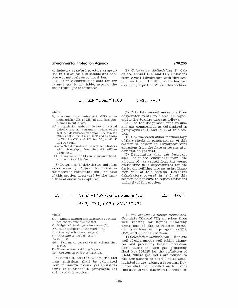
(2) Calculation Methodology 2. Cal-culate annual CH4 and CO2 emissions from glycol dehydrators with through-put less than 0.4 million cubic feet per day using Equation W–5 of this section:
Where:
Es,i = Annual total volumetric GHG emis-sions (either CO2 or CH4) at standard con-ditions in cubic feet.
EFi = Population emission factors for glycol dehydrators in thousand standard cubic feet per dehydrator per year. Use 74.5 for CH4 and 3.26 for CO2 at 68 °F and 14.7 psia or 73.4 for CH4 and 3.21 for CO2 at 60 °F and 14.7 psia.
Count = Total number of glycol dehydrators with throughput less than 0.4 million cubic feet.
1000 = Conversion of EFi in thousand stand-ard cubic to cubic feet.
(3) Determine if dehydrator unit has vapor recovery. Adjust the emissions estimated in paragraphs (e)(1) or (e)(2) of this section downward by the mag-nitude of emissions captured.
(4) Calculate annual emissions from dehydrator vents to flares or regen-erator fire-box/fire tubes as follows:
(A) Use the dehydrator vent volume and gas composition as determined in paragraphs (e)(1) and (e)(2) of this sec-tion.
(B) Use the calculation methodology of flare stacks in paragraph (n) of this section to determine dehydrator vent emissions from the flare or regenerator combustion gas vent.
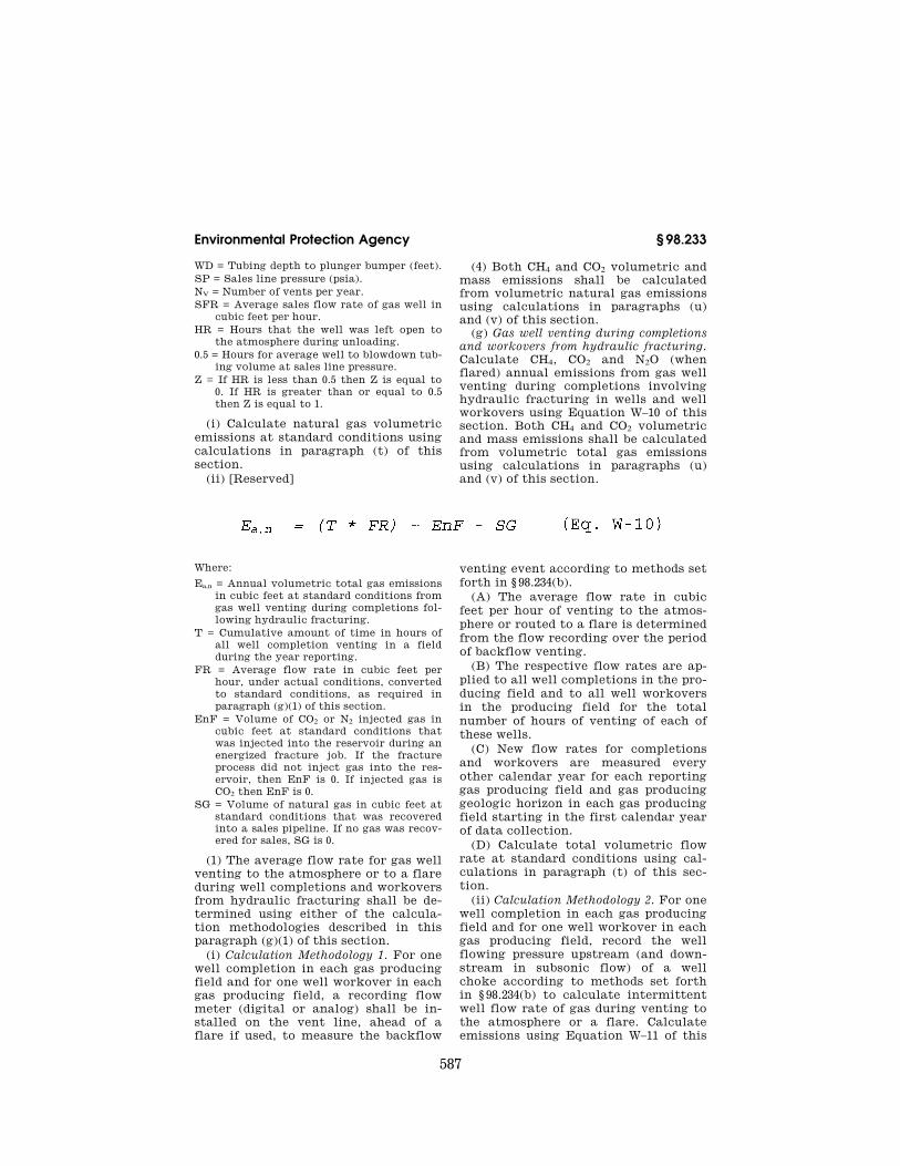
(5) Dehydrators that use desiccant shall calculate emissions from the amount of gas vented from the vessel every time it is depressurized for the desiccant refilling process using Equa-tion W–6 of this section. Desiccant dehydrators covered in (e)(5) of this section do not have to report emissions under (i) of this section.
Where:
Es,n = Annual natural gas emissions at stand-ard conditions in cubic feet.
H = Height of the dehydrator vessel (ft). D = Inside diameter of the vessel (ft). P1 = Atmospheric pressure (psia). P2 = Pressure of the gas (psia). P = pi (3.14). %G = Percent of packed vessel volume that
is gas. T = Time between refilling (days). 100 = Conversion of %G to fraction.
(6) Both CH4 and CO2 volumetric and mass emissions shall be calculated from volumetric natural gas emissions using calculations in paragraphs (u) and (v) of this section.
(f) Well venting for liquids unloadings. Calculate CO2 and CH4 emissions from well venting for liquids unloading using one of the calculation meth-odologies described in paragraphs (f)(1), (f)(2) or (f)(3) of this section.
(1) Calculation Methodology 1. For one well of each unique well tubing diame-ter and producing horizon/formation combination in each gas producing field (see § 98.238 for the definition of Field) where gas wells are vented to the atmosphere to expel liquids accu-mulated in the tubing, a recording flow meter shall be installed on the vent line used to vent gas from the well (e.g.
VerDate Mar<15>2010 14:18 Sep 30, 2011 Jkt 223164 PO 00000 Frm 00597 Fmt 8010 Sfmt 8002 Y:\SGML\223164.XXX 223164 ER
30N
O10
.177
</G
PH
>E
R30
NO
10.1
78<
/GP
H>
wre
ier-
avile
s on
DS
K7S
PT
VN
1PR
OD
with
CF
R

586
40 CFR Ch. I (7–1–11 Edition) § 98.233
on the vent line off the wellhead sepa-rator or atmospheric storage tank) ac-cording to methods set forth in
§ 98.234(b). Calculate emissions from well venting for liquids unloading using Equation W–7 of this section.
Where: Ea,n = Annual natural gas emissions at actual
conditions in cubic feet. Th,t = Cumulative amount of time in hours of
venting from all wells of the same tubing diameter (t) and producing horizon (h)/ formation combination during the year.
FRh,t = Average flow rate in cubic feet per hour of the measured well venting for the duration of the liquids unloading, under actual conditions as determined in para-graph (f)(1)(i) of this section.
(i) Determine the well vent average flow rate as specified under paragraph (f)(1)(i) of this section.
(A) The average flow rate per hour of venting is calculated for each unique tubing diameter and producing horizon/ formation combination in each pro-ducing field by averaging the recorded flow rates for the recorded time of one
representative well venting to the at-mosphere.
(B) This average flow rate is applied to all wells in the field that have the same tubing diameter and producing horizon/formation combination, for the number of hours of venting these wells.
(C) A new average flow rate is cal-culated every other calendar year for each reporting field and horizon start-ing the first calendar year of data col-lection.
(ii) Calculate natural gas volumetric emissions at standard conditions using calculations in paragraph (t) of this section.
(2) Calculation Methodology 2. Cal-culate emissions from each well vent-ing for liquids unloading using Equa-tion W–8 of this section.
Where: Ea,n = Annual natural gas emissions at actual
conditions, in cubic feet/year. 0.37×10¥3 = {3.14 (pi)/4}/{14.7*144} (psia con-
verted to pounds per square feet). CD = Casing diameter (inches). WD = Well depth to first producing horizon
(feet). SP = Shut-in pressure (psia). NV = Number of vents per year. SFR = Average sales flow rate of gas well in
cubic feet per hour. HR = Hours that the well was left open to
the atmosphere during unloading. 1.0 = Hours for average well to blowdown cas-
ing volume at shut-in pressure.
Z = If HR is less than 1.0 then Z is equal to 0. If HR is greater than or equal to 1.0 then Z is equal to 1.
(i) Calculate natural gas volumetric emissions at standard conditions using calculations in paragraph (t) of this section.
(ii) [Reserved] (3) Calculation Methodology 3. Cal-
culate emissions from each well vent-ing to the atmosphere for liquids un-loading with plunger lift assist using Equation W–9 of this section.
Where:
Ea,n = Annual natural gas emissions at actual conditions, in cubic feet/year.
0.37×10-3 = {3.14 (pi)/4}/{14.7*144} (psia con-verted to pounds per square feet).
TD = Tubing diameter (inches).
VerDate Mar<15>2010 14:18 Sep 30, 2011 Jkt 223164 PO 00000 Frm 00598 Fmt 8010 Sfmt 8002 Y:\SGML\223164.XXX 223164 ER
30N
O10
.179
</G
PH
>E
R30
NO
10.1
80<
/GP
H>
ER
30N
O10
.181
</G
PH
>
wre
ier-
avile
s on
DS
K7S
PT
VN
1PR
OD
with
CF
R
587
Environmental Protection Agency § 98.233
WD = Tubing depth to plunger bumper (feet). SP = Sales line pressure (psia). NV = Number of vents per year. SFR = Average sales flow rate of gas well in
cubic feet per hour. HR = Hours that the well was left open to
the atmosphere during unloading. 0.5 = Hours for average well to blowdown tub-
ing volume at sales line pressure. Z = If HR is less than 0.5 then Z is equal to
0. If HR is greater than or equal to 0.5 then Z is equal to 1.
(i) Calculate natural gas volumetric emissions at standard conditions using calculations in paragraph (t) of this section.
(ii) [Reserved]
(4) Both CH4 and CO2 volumetric and mass emissions shall be calculated from volumetric natural gas emissions using calculations in paragraphs (u) and (v) of this section.
(g) Gas well venting during completions and workovers from hydraulic fracturing. Calculate CH4, CO2 and N2O (when flared) annual emissions from gas well venting during completions involving hydraulic fracturing in wells and well workovers using Equation W–10 of this section. Both CH4 and CO2 volumetric and mass emissions shall be calculated from volumetric total gas emissions using calculations in paragraphs (u) and (v) of this section.
Where:
Ea,n = Annual volumetric total gas emissions in cubic feet at standard conditions from gas well venting during completions fol-lowing hydraulic fracturing.
T = Cumulative amount of time in hours of all well completion venting in a field during the year reporting.
FR = Average flow rate in cubic feet per hour, under actual conditions, converted to standard conditions, as required in paragraph (g)(1) of this section.
EnF = Volume of CO2 or N2 injected gas in cubic feet at standard conditions that was injected into the reservoir during an energized fracture job. If the fracture process did not inject gas into the res-ervoir, then EnF is 0. If injected gas is CO2 then EnF is 0.
SG = Volume of natural gas in cubic feet at standard conditions that was recovered into a sales pipeline. If no gas was recov-ered for sales, SG is 0.
(1) The average flow rate for gas well venting to the atmosphere or to a flare during well completions and workovers from hydraulic fracturing shall be de-termined using either of the calcula-tion methodologies described in this paragraph (g)(1) of this section.
(i) Calculation Methodology 1. For one well completion in each gas producing field and for one well workover in each gas producing field, a recording flow meter (digital or analog) shall be in-stalled on the vent line, ahead of a flare if used, to measure the backflow
venting event according to methods set forth in § 98.234(b).
(A) The average flow rate in cubic feet per hour of venting to the atmos-phere or routed to a flare is determined from the flow recording over the period of backflow venting.
(B) The respective flow rates are ap-plied to all well completions in the pro-ducing field and to all well workovers in the producing field for the total number of hours of venting of each of these wells.
(C) New flow rates for completions and workovers are measured every other calendar year for each reporting gas producing field and gas producing geologic horizon in each gas producing field starting in the first calendar year of data collection.
(D) Calculate total volumetric flow rate at standard conditions using cal-culations in paragraph (t) of this sec-tion.
(ii) Calculation Methodology 2. For one well completion in each gas producing field and for one well workover in each gas producing field, record the well flowing pressure upstream (and down-stream in subsonic flow) of a well choke according to methods set forth in § 98.234(b) to calculate intermittent well flow rate of gas during venting to the atmosphere or a flare. Calculate emissions using Equation W–11 of this
VerDate Mar<15>2010 14:18 Sep 30, 2011 Jkt 223164 PO 00000 Frm 00599 Fmt 8010 Sfmt 8002 Y:\SGML\223164.XXX 223164 ER
30N
O10
.182
</G
PH
>
wre
ier-
avile
s on
DS
K7S
PT
VN
1PR
OD
with
CF
R

588
40 CFR Ch. I (7–1–11 Edition) § 98.233
section for subsonic flow or Equation W–12 of this section for sonic flow:
Where: FR = Average flow rate in cubic feet per
hour, under subsonic flow conditions. A = Cross sectional area of orifice (m2). P1 = Upstream pressure (psia).
Tu = Upstream temperature (degrees Kelvin). P2 = Downstream pressure (psia). 3430 = Constant with units of m2/(sec2 * K). 1.27*105 = Conversion from m3/second to ft3/
hour.
Where: FR = Average flow rate in cubic feet per
hour, under sonic flow conditions. A = Cross sectional area of orifice (m2). Tu = Upstream temperature (degrees Kelvin). 187.08 = Constant with units of m2/(sec2 * K). 1.27*105 = Conversion from m3/second to ft3/
hour.
(A) The average flow rate in cubic feet per hour of venting across the choke is calculated for one well com-pletion in each gas producing field and for one well workover in each gas pro-ducing field by averaging the gas flow rates during venting to the atmosphere or routing to a flare.
(B) The respective flow rates are ap-plied to all well completions in the gas producing field and to all well workovers in the gas producing field for the total number of hours of vent-ing of each of these wells.
(C) Flow rates for completions and workovers in each field shall be cal-culated once every two years for each reporting gas producing field and geo-logic horizon in each gas producing field starting in the first calendar year of data collection.
(D) Calculate total volumetric flow rate at standard conditions using cal-culations in paragraph (t) of this sec-tion.
(2) The volume of CO2 or N2 injected into the well reservoir during energized hydraulic fractures will be measured using an appropriate meter as de-scribed in 98.234(b) or using receipts of
gas purchases that are used for the en-ergized fracture job.
(i) Calculate gas volume at standard conditions using calculations in para-graph (t) of this section.
(ii) [Reserved] (3) The volume of recovered comple-
tion gas sent to a sales line will be measured using existing company records. If data does not exist on sales gas, then an appropriate meter as de-scribed in 98.234(b) may be used.
(i) Calculate gas volume at standard conditions using calculations in para-graph (t) of this section.
(ii) [Reserved] (4) Both CH4 and CO2 volumetric and
mass emissions shall be calculated from volumetric total emissions using calculations in paragraphs (u) and (v) of this section.
(5) Determine if the well completion or workover from hydraulic fracturing recovered gas with purpose designed equipment that separates saleable gas from the backflow, and sent this gas to a sales line (e.g. reduced emissions completion).
(i) Use the factor SG in Equation W– 10 of this section, to adjust the emis-sions estimated in paragraphs (g)(1) through (g)(4) of this section by the magnitude of emissions captured using reduced emission completions as deter-mined by engineering estimate based on best available data.
(ii) [Reserved]
VerDate Mar<15>2010 14:18 Sep 30, 2011 Jkt 223164 PO 00000 Frm 00600 Fmt 8010 Sfmt 8002 Y:\SGML\223164.XXX 223164 ER
30N
O10
.183
</G
PH
>E
R30
NO
10.1
84<
/GP
H>
wre
ier-
avile
s on
DS
K7S
PT
VN
1PR
OD
with
CF
R

589
Environmental Protection Agency § 98.233
(6) Calculate annual emissions from gas well venting during well comple-tions and workovers from hydraulic fracturing to flares as follows:
(i) Use the total gas well venting vol-ume during well completions and workovers as determined in paragraph (g) of this section.
(ii) Use the calculation methodology of flare stacks in paragraph (n) of this section to determine gas well venting during well completions and workovers using hydraulic fracturing emissions from the flare. This adjustment to
emissions from completions using flar-ing versus completions without flaring accounts for the conversion of CH4 to CO2 in the flare.
(h) Gas well venting during completions and workovers without hydraulic frac-turing. Calculate CH4, CO2 and N2O (when flared) emissions from each gas well venting during well completions and workovers not involving hydraulic fracturing and well workovers not in-volving hydraulic fracturing using Equation W–13 of this section:
Where:
Ea,n = Annual natural gas emissions in cubic feet at actual conditions from gas well venting during well completions and workovers without hydraulic fracturing.
Nwo = Number of workovers per field not in-volving hydraulic fracturing in the re-porting year.
EFwo = Emission Factor for non-hydraulic fracture well workover venting in actual cubic feet per workover. EFwo = 2,454 standard cubic feet per well workover without hydraulic fracturing.
f = Total number of well completions with-out hydraulic fracturing in a field.
Vf = Average daily gas production rate in cubic feet per hour of each well comple-tion without hydraulic fracturing. This is the total annual gas production vol-ume divided by total number of hours the wells produced to the sales line. For com-pleted wells that have not established a production rate, you may use the aver-age flow rate from the first 30 days of production. In the event that the well is completed less than 30 days from the end of the calendar year, the first 30 days of the production straddling the current and following calendar years shall be used.
Tf = Time each well completion without hy-draulic fracturing was venting in hours during the year.
(1) Calculate natural gas volumetric emissions at standard conditions using calculations in paragraph (t) of this section.
(2) Both CH4 and CO2 volumetric and mass emissions shall be calculated from volumetric natural gas emissions
using calculations in paragraphs (u) and (v) of this section.
(3) Calculate annual emissions from gas well venting during well comple-tions and workovers not involving hy-draulic fracturing to flares as follows:
(i) Use the gas well venting volume during well completions and workovers as determined in paragraph (h) of this section.
(ii) Use the calculation methodology of flare stacks in paragraph (n) of this section to determine gas well venting during well completions and workovers emissions without hydraulic fracturing from the flare.
(i) Blowdown vent stacks. Calculate CO2 and CH4 blowdown vent stack emissions from depressurizing equip-ment to the atmosphere (excluding de-pressurizing to a flare, over-pressure relief, operating pressure control vent-ing and blowdown of non-GHG gases; desiccant dehydrator blowdown vent-ing before reloading is covered in para-graph (e)(5) of this section) as follows:
(1) Calculate the total volume (in-cluding pipelines, compressor case or cylinders, manifolds, suction bottles, discharge bottles, and vessels) between isolation valves determined by engi-neering estimate based on best avail-able data.
(2) If the total volume between isola-tion valves is greater than or equal to 50 standard cubic feet, retain logs of the number of blowdowns for each
VerDate Mar<15>2010 14:18 Sep 30, 2011 Jkt 223164 PO 00000 Frm 00601 Fmt 8010 Sfmt 8002 Y:\SGML\223164.XXX 223164 ER
30N
O10
.185
</G
PH
>
wre
ier-
avile
s on
DS
K7S
PT
VN
1PR
OD
with
CF
R

590
40 CFR Ch. I (7–1–11 Edition) § 98.233
equipment type (including but not lim-ited to compressors, vessels, pipelines, headers, fractionators, and tanks). Blowdown volumes smaller than 50 standard cubic feet are exempt from re-
porting under paragraph (i) of this sec-tion.
(3) Calculate the total annual venting emissions for each equipment type using Equation W–14 of this section:
Where: Es,n = Annual natural gas venting emissions
at standard conditions from blowdowns in cubic feet.
N = Number of repetitive blowdowns for each equipment type of a unique volume in calendar year.
Vv = Total volume of blowdown equipment chambers (including pipelines, compres-sors and vessels) between isolation valves in cubic feet.
C = Purge factor that is 1 if the equipment is not purged or zero if the equipment is purged using non-GHG gases.
Ts = Temperature at standard conditions ( °F).
Ta = Temperature at actual conditions in the blowdown equipment chamber ( °F).
Ps = Absolute pressure at standard condi-tions (psia).
Pa = Absolute pressure at actual conditions in the blowdown equipment chamber (psia).
(4) Calculate both CH4 and CO2 mass emissions from volumetric natural gas emissions using calculations in para-graph (v) of this section.
(5) Calculate total annual venting emissions for all blowdown vent stacks by adding all standard volumetric and mass emissions determined in Equation W–14 and paragraph (i)(4) of this sec-tion.
(j) Onshore production storage tanks. Calculate CH4, CO2 and N2O (when flared) emissions from atmospheric pressure fixed roof storage tanks re-ceiving hydrocarbon produced liquids from onshore petroleum and natural gas production facilities (including sta-tionary liquid storage not owned or op-erated by the reporter), calculate an-nual CH4 and CO2 emissions using any of the calculation methodologies de-scribed in this paragraph (j).
(1) Calculation Methodology 1. For sep-arators with oil throughput greater than or equal to 10 barrels per day. Cal-
culate annual CH4 and CO2 emissions from onshore production storage tanks using operating conditions in the last wellhead gas-liquid separator before liquid transfer to storage tanks. Cal-culate flashing emissions with a soft-ware program, such as AspenTech HYSYS® or API 4697 E&P Tank, that uses the Peng-Robinson equation of state, models flashing emissions, and speciates CH4 and CO2 emissions that will result when the oil from the sepa-rator enters an atmospheric pressure storage tank. A minimum of the fol-lowing parameters determined for typ-ical operating conditions over the year by engineering estimate and process knowledge based on best available data must be used to characterize emissions from liquid transferred to tanks.
(i) Separator temperature. (ii) Separator pressure. (iii) Sales oil or stabilized oil API
gravity. (iv) Sales oil or stabilized oil produc-
tion rate. (v) Ambient air temperature. (vi) Ambient air pressure. (vii) Separator oil composition and
Reid vapor pressure. If this data is not available, determine these parameters by selecting one of the methods de-scribed under paragraph (j)(1)(viii) of this section.
(A) If separator oil composition and Reid vapor pressure default data are provided with the software program, select the default values that most closely match your separator pressure first, and API gravity secondarily.
(B) If separator oil composition and Reid vapor pressure data are available through your previous analysis, select the latest available analysis that is representative of produced crude oil or condensate from the field.
VerDate Mar<15>2010 14:18 Sep 30, 2011 Jkt 223164 PO 00000 Frm 00602 Fmt 8010 Sfmt 8002 Y:\SGML\223164.XXX 223164 ER
30N
O10
.186
</G
PH
>
wre
ier-
avile
s on
DS
K7S
PT
VN
1PR
OD
with
CF
R

591
Environmental Protection Agency § 98.233
(C) Analyze a representative sample of separator oil in each field for oil composition and Reid vapor pressure using an appropriate standard method published by a consensus-based stand-ards organization.
(2) Calculation Methodology 2. Cal-culate annual CH4 and CO2 emissions from onshore production storage tanks for wellhead gas-liquid separators with oil throughput greater than or equal to 10 barrels per day by assuming that all of the CH4 and CO2 in solution at sepa-rator temperature and pressure is emitted from oil sent to storage tanks. You may use an appropriate standard method published by a consensus-based standards organization if such a meth-od exists or you may use an industry standard practice as described in § 98.234(b)(1) to sample and analyze sep-arator oil composition at separator pressure and temperature.
(3) Calculation Methodology 3. For wells with oil production greater than or equal to 10 barrels per day that flow directly to atmospheric storage tanks without passing through a wellhead separator, calculate CH4 and CO2 emis-sions by either of the methods in para-graph (j)(3) of this section:
(i) If well production oil and gas com-positions are available through your previous analysis, select the latest available analysis that is representa-tive of produced oil and gas from the field and assume all of the CH4 and CO2 in both oil and gas are emitted from the tank.
(ii) If well production oil and gas compositions are not available, use de-fault oil and gas compositions in soft-ware programs, such as API 4697 E&P Tank, that most closely match your well production gas/oil ratio and API gravity and assume all of the CH4 and CO2 in both oil and gas are emitted from the tank.
(4) Calculation Methodology 4. For wells with oil production greater than or equal to 10 barrels per day that flow to a separator not at the well pad, cal-culate CH4 and CO2 emissions by either of the methods in paragraph (j)(4) of this section:
(i) If well production oil and gas com-positions are available through your previous analysis, select the latest available analysis that is representa-tive of oil at separator pressure deter-mined by best available data and as-sume all of the CH4 and CO2 in the oil is emitted from the tank.
(ii) If well production oil composition is not available, use default oil com-position in software programs, such as API 4697 E&P Tank, that most closely match your well production API grav-ity and pressure in the off-well pad sep-arator determined by best available data. Assume all of the CH4 and CO2 in the oil phase is emitted from the tank.
(5) Calculation Methodology 5. For well pad gas-liquid separators and for wells flowing off a well pad without passing through a gas-liquid separator with throughput less than 10 barrels per day use Equation W–15 of this section:
Where:
Es,i = Annual total volumetric GHG emis-sions (either CO2 or CH4) at standard con-ditions in cubic feet.
EFi = Populations emission factor for separa-tors and wells in thousand standard cubic feet per separator or well per year, for crude oil use 4.3 for CH4 and 2.9 for CO2 at 68 °F and 14.7 psia, and for gas condensate use 17.8 for CH4 and 2.9 for CO2 at 68 °F and 14.7 psia.
Count = Total number of separators and wells with throughput less than 10 bar-rels per day.
(6) Determine if the storage tank re-ceiving your separator oil has a vapor recovery system.
(i) Adjust the emissions estimated in paragraphs (j)(1) through (j)(5) of this section downward by the magnitude of emissions recovered using a vapor re-covery system as determined by engi-neering estimate based on best avail-able data.
(ii) [Reserved] (7) Determine if the storage tank re-
ceiving your separator oil is sent to flare(s).
VerDate Mar<15>2010 14:18 Sep 30, 2011 Jkt 223164 PO 00000 Frm 00603 Fmt 8010 Sfmt 8002 Y:\SGML\223164.XXX 223164 ER
30N
O10
.187
</G
PH
>
wre
ier-
avile
s on
DS
K7S
PT
VN
1PR
OD
with
CF
R

592
40 CFR Ch. I (7–1–11 Edition) § 98.233
(i) Use your separator flash gas vol-ume and gas composition as deter-mined in this section.
(ii) Use the calculation methodology of flare stacks in paragraph (n) of this section to determine your contribution
to storage tank emissions from the flare.
(8) Calculate emissions from occur-rences of well pad gas-liquid separator liquid dump valves not closing during the calendar year by using Equation W–16 of this section.
Where: Es,i = Annual total volumetric GHG emis-
sions at standard conditions from each storage tank in cubic feet.
En = Storage tank emissions as determined in Calculation Methodologies 1, 2, or 5 in paragraphs (j)(1) through (j)(5) of this section (with wellhead separators) during time Tn in cubic feet per hour.
Tn = Total time the dump valve is not clos-ing properly in the calendar year in hours. Tn is estimated by maintenance or operations records (records) such that when a record shows the valve to be open improperly, it is assumed the valve was open for the entire time period preceding the record starting at either the begin-ning of the calendar year or the previous record showing it closed properly within the calendar year. If a subsequent record shows it is closing properly, then assume from that time forward the valve closed properly until either the next record of it not closing properly or, if there is no subsequent record, the end of the cal-endar year.
CFn = Correction factor for tank emissions for time period Tn is 3.87 for crude oil production. Correction factor for tank emissions for time period Tn is 5.37 for gas condensate production. Correction factor for tank emissions for time period Tn is 1.0 for periods when the dump valve is closed.
Et = Storage tank emissions as determined in Calculation Methodologies 1, 2, or 3 in paragraphs (j)(1) through (j)(5) of this section at maintenance or operations during the time the dump valve is clos-ing properly (ie. 8760–Tn) in cubic feet per hour.
(9) Calculate both CH4 and CO2 mass emissions from volumetric natural gas emissions using calculations in para-graph (v) of this section.
(k) Transmission storage tanks. For condensate storage tanks, either water or hydrocarbon, without vapor recov-ery or thermal control devices in on-shore natural gas transmission com-
pression facilities calculate CH4, CO2 and N2O (when flared) annual emissions from compressor scrubber dump valve leakage as follows:
(1) Monitor the tank vapor vent stack annually for emissions using an optical gas imaging instrument accord-ing to methods set forth in § 98.234(a)(1) for a duration of 5 minutes. Or you may annually monitor leakage through compressor scrubber dump valve(s) into the tank using an acoustic leak detec-tion device according to methods set forth in § 98.234(a)(5).
(2) If the tank vapors are continuous for 5 minutes, or the acoustic leak de-tection device detects a leak, then use one of the following two methods in paragraph (k)(2) of this section to quantify emissions:
(i) Use a meter, such as a turbine meter, to estimate tank vapor volumes according to methods set forth in § 98.234(b). If you do not have a contin-uous flow measurement device, you may install a flow measuring device on the tank vapor vent stack.
(ii) Use an acoustic leak detection device on each scrubber dump valve connected to the tank according to the method set forth in § 98.234(a)(5).
(iii) Use the appropriate gas composi-tion in paragraph (u)(2)(iii) of this sec-tion.
(3) If the leaking dump valve(s) is fixed following leak detection, the an-nual emissions shall be calculated from the beginning of the calendar year to the time the valve(s) is repaired.
(4) Calculate emissions from storage tanks to flares as follows:
(i) Use the storage tank emissions volume and gas composition as deter-mined in either paragraph (j)(1)of this
VerDate Mar<15>2010 14:18 Sep 30, 2011 Jkt 223164 PO 00000 Frm 00604 Fmt 8010 Sfmt 8002 Y:\SGML\223164.XXX 223164 ER
30N
O10
.188
</G
PH
>
wre
ier-
avile
s on
DS
K7S
PT
VN
1PR
OD
with
CF
R

593
Environmental Protection Agency § 98.233
section or with an acoustic leak detec-tion device in paragraphs (k)(1) through (k)(3) of this section.
(ii) Use the calculation methodology of flare stacks in paragraph (n) of this section to determine storage tank emissions from the flare.
(l) Well testing venting and flaring. Calculate CH4, CO2 and N2O (when flared) well testing venting and flaring emissions as follows:
(1) Determine the gas to oil ratio (GOR) of the hydrocarbon production from each well tested.
(2) If GOR cannot be determined from your available data, then you must measure quantities reported in this section according to one of the two procedures in paragraph (l)(2) of this section to determine GOR:
(i) You may use an appropriate standard method published by a con-sensus-based standards organization if such a method exists.
(ii) Or you may use an industry standard practice as described in § 98.234(b).
(3) Estimate venting emissions using Equation W–17 of this section.
Where: Ea,n = Annual volumetric natural gas emis-
sions from well testing in cubic feet under actual conditions.
GOR = Gas to oil ratio in cubic feet of gas per barrel of oil; oil here refers to hydro-carbon liquids produced of all API gravities.
FR = Flow rate in barrels of oil per day for the well being tested.
D = Number of days during the year, the well is tested.
(4) Calculate natural gas volumetric emissions at standard conditions using calculations in paragraph (t) of this section.
(5) Calculate both CH4 and CO2 volu-metric and mass emissions from volu-metric natural gas emissions using cal-culations in paragraphs (u) and (v) of this section.
(6) Calculate emissions from well testing to flares as follows:
(i) Use the well testing emissions vol-ume and gas composition as deter-mined in paragraphs (l)(1) through (3) of this section.
(ii) Use the calculation methodology of flare stacks in paragraph (n) of this
section to determine well testing emis-sions from the flare.
(m) Associated gas venting and flaring. Calculate CH4, CO2 and N2O (when flared) associated gas venting and flar-ing emissions not in conjunction with well testing (refer to paragraph (l): Well testing venting and flaring of this section) as follows:
(1) Determine the GOR of the hydro-carbon production from each well whose associated natural gas is vented or flared. If GOR from each well is not available, the GOR from a cluster of wells in the same field shall be used.
(2) If GOR cannot be determined from your available data, then use one of the two procedures in paragraph (m)(2) of this section to determine GOR:
(i) You may use an appropriate standard method published by a con-sensus-based standards organization if such a method exists.
(ii) Or you may use an industry standard practice as described in § 98.234(b).
(3) Estimate venting emissions using Equation W–18 of this section.
Where:
Ea,n = Annual volumetric natural gas emis-sions from associated gas venting under actual conditions, in cubic feet.
GOR = Gas to oil ratio in cubic feet of gas per barrel of oil; oil here refers to hydro-carbon liquids produced of all API gravities.
VerDate Mar<15>2010 14:18 Sep 30, 2011 Jkt 223164 PO 00000 Frm 00605 Fmt 8010 Sfmt 8002 Y:\SGML\223164.XXX 223164 ER
30N
O10
.189
</G
PH
>E
R30
NO
10.1
90<
/GP
H>
wre
ier-
avile
s on
DS
K7S
PT
VN
1PR
OD
with
CF
R

594
40 CFR Ch. I (7–1–11 Edition) § 98.233
V = Volume of oil produced in barrels in the calendar year during which associated gas was vented or flared.
(4) Calculate natural gas volumetric emissions at standard conditions using calculations in paragraph (t) of this section.
(5) Calculate both CH4 and CO2 volu-metric and mass emissions from volu-metric natural gas emissions using cal-culations in paragraphs (u) and (v) of this section.
(6) Calculate emissions from associ-ated natural gas to flares as follows:
(i) Use the associated natural gas vol-ume and gas composition as deter-mined in paragraph (m)(1) through (4) of this section.
(ii) Use the calculation methodology of flare stacks in paragraph (n) of this section to determine associated gas emissions from the flare.
(n) Flare stack emissions. Calculate CO2, CH4, and N2O emissions from a flare stack as follows:
(1) If you have a continuous flow measurement device on the flare, you must use the measured flow volumes to calculate the flare gas emissions. If all of the flare gas is not measured by the existing flow measurement device, then the flow not measured can be esti-mated using engineering calculations based on best available data or com-pany records. If you do not have a con-tinuous flow measurement device on the flare, you can install a flow meas-uring device on the flare or use engi-neering calculations based on process knowledge, company records, and best available data.
(2) If you have a continuous gas com-position analyzer on gas to the flare, you must use these compositions in calculating emissions. If you do not have a continuous gas composition an-alyzer on gas to the flare, you must use the appropriate gas compositions for each stream of hydrocarbons going to the flare as follows:
(i) For onshore natural gas produc-tion, determine natural gas composi-tion using (u)(2)(i) of this section.
(ii) For onshore natural gas proc-essing, when the stream going to flare is natural gas, use the GHG mole per-cent in feed natural gas for all streams upstream of the de-methanizer or dew point control, and GHG mole percent in facility specific residue gas to trans-mission pipeline systems for all emis-sions sources downstream of the de- methanizer overhead or dew point con-trol for onshore natural gas processing facilities.
(iii) When the stream going to the flare is a hydrocarbon product stream, such as ethane, propane, butane, pen-tane-plus and mixed light hydro-carbons, then use a representative composition from the source for the stream determined by engineering cal-culation based on process knowledge and best available data.
(3) Determine flare combustion effi-ciency from manufacturer. If not avail-able, assume that flare combustion ef-ficiency is 98 percent.
(4) Calculate GHG volumetric emis-sions at actual conditions using Equa-tions W–19, W–20, and W–21 of this sec-tion.
Where:
Ea,CH4(un-combusted) = Contribution of an-nual un-combusted CH4 emissions from
flare stack in cubic feet, under actual conditions.
Ea,CO2(un-combusted) = Contribution of an-nual un-combusted CO2 emissions from
VerDate Mar<15>2010 14:18 Sep 30, 2011 Jkt 223164 PO 00000 Frm 00606 Fmt 8010 Sfmt 8002 Y:\SGML\223164.XXX 223164 ER
30N
O10
.191
</G
PH
>
wre
ier-
avile
s on
DS
K7S
PT
VN
1PR
OD
with
CF
R

595
Environmental Protection Agency § 98.233
flare stack in cubic feet, under actual conditions.
Ea,CO2(combusted) = Contribution of annual combusted CO2 emissions from flare stack in cubic feet, under actual condi-tions.
Va = Volume of gas sent to flare in cubic feet, during the year.
h = Fraction of gas combusted by a burning flare (default is 0.98). For gas sent to an unlit flare, h is zero.
XCH4 = Mole fraction of CH4 in gas to the flare.
XCO2 = Mole fraction of CO2 in gas to the flare.
Yj = Mole fraction of gas hydrocarbon con-stituents j (such as methane, ethane, propane, butane, and pentanes-plus).
Rj = Number of carbon atoms in the gas hy-drocarbon constituent j: 1 for methane, 2 for ethane, 3 for propane, 4 for butane, and 5 for pentanes-plus).
(5) Calculate GHG volumetric emis-sions at standard conditions using cal-culations in paragraph (t) of this sec-tion.
(6) Calculate both CH4 and CO2 mass emissions from volumetric CH4 and CO2 emissions using calculation in para-graph (v) of this section.
(7) Calculate total annual emission from flare stacks by summing Equa-tion W–40, Equation W–19, Equation W– 20 and Equation W–21 of this section.
(8) Calculate N2O emissions from flare stacks using Equation W–40 in paragraph (z) of this section.
(9) The flare emissions determined under paragraph (n) of this section must be corrected for flare emissions calculated and reported under other paragraphs of this section to avoid dou-ble counting of these emissions.
(o) Centrifugal compressor venting. Cal-culate CH4, CO2 and N2O (when flared) emissions from both wet seal and dry seal centrifugal compressor vents as follows:
(1) For each centrifugal compressor covered by § 98.232 (d)(2), (e)(2), (f)(2), (g)(2), and (h)(2) you must conduct an annual measurement in the operating mode in which it is found. Measure emissions from all vents (including emissions manifolded to common vents) including wet seal oil degassing
vents, unit isolation valve vents, and blowdown valve vents. Record emis-sions from the following vent types in the specified compressor modes during the annual measurement.
(i) Operating mode, blowdown valve leakage through the blowdown vent, wet seal and dry seal compressors.
(ii) Operating mode, wet seal oil degassing vents.
(iii) Not operating, depressurized mode, unit isolation valve leakage through open blowdown vent, without blind flanges, wet seal and dry seal compressors.
(A) For the not operating, depressur-ized mode, each compressor must be measured at least once in any three consecutive calendar years. If a com-pressor is not operated and has blind flanges in place throughout the 3 year period, measurement is not required in this mode. If the compressor is in standby depressurized mode without blind flanges in place and is not oper-ated throughout the 3 year period, it must be measured in the standby de-pressurized mode.
(2) For wet seal oil degassing vents, determine vapor volumes sent to an at-mospheric vent or flare, using a tem-porary meter such as a vane anemom-eter or permanent flow meter accord-ing to 98.234(b) of this section. If you do not have a permanent flow meter, you may install a permanent flow meter on the wet seal oil degassing tank vent.
(3) For blowdown valve leakage and unit isolation valve leakage to open ended vents, you can use one of the fol-lowing methods: Calibrated bagging or high volume sampler according to methods set forth in § 98.234(c) and § 98.234(d), respectively. For through valve leakage, such as isolation valves, you may use an acoustic leak detection device according to methods set forth in § 98.234(a). If you do not have a flow meter, you may install a port for inser-tion of a temporary meter, or a perma-nent flow meter, on the vents.
(4) Estimate annual emissions using the flow measurement and Equation W–22 of this section.
VerDate Mar<15>2010 14:18 Sep 30, 2011 Jkt 223164 PO 00000 Frm 00607 Fmt 8010 Sfmt 8002 Y:\SGML\223164.XXX 223164wre
ier-
avile
s on
DS
K7S
PT
VN
1PR
OD
with
CF
R

596
40 CFR Ch. I (7–1–11 Edition) § 98.233
Where: Es,i,m = Annual GHGi (either CH4 or CO2) volu-
metric emissions at standard conditions, in cubic feet.
MTm = Measured gas emissions in standard cubic feet per hour.
Tm = Total time the compressor is in the mode for which Es,i is being calculated, in the calendar year in hours.
Mi,m = Mole fraction of GHGi in the vent gas; use the appropriate gas compositions in paragraph (u)(2) of this section.
Bm = Fraction of operating time that the vent gas is sent to vapor recovery or fuel gas as determined by keeping logs of the number of operating hours for the vapor recovery system and the time that vent gas is directed to the fuel gas system or sales.
(5) Calculate annual emissions from each centrifugal compressor using Equation W–23 of this section.
Where: Es,i = Annual total volumetric GHG emis-
sions at standard conditions from each centrifugal compressor in cubic feet.
EFm = Reporter emission factor for each mode m, in cubic feet per hour, from Equation W–24 of this section as cal-culated in paragraph 6.
Tm = Total time in hours per year the com-pressor was in each mode, as listed in paragraph (o)(1)(i) through (o)(1)(iii).
GHGi = For onshore natural gas processing facilities, concentration of GHG i, CH4 or CO2, in produced natural gas or feed nat-ural gas; for other facilities listed in § 98.230(a)(4) through (a)(8),GHGi equals 1.
(6) You shall use the flow measure-ments of operating mode wet seal oil degassing vent, operating mode blow-down valve vent and not operating de-pressurized mode isolation valve vent for all the reporter’s compressor modes not measured in the calendar year to develop the following emission factors using Equation W–24 of this section for each emission source and mode as list-ed in paragraph (o)(1)(i) through (o)(1)(iii).
Where:
EFm = Reporter emission factors for com-pressor in the three modes m (as listed in paragraph (o)(1)(i) through (o)(1)(iii)) in cubic feet per hour.
MTm = Flow Measurements from all cen-trifugal compressor vents in each mode in (o)(1)(i) through (o)(1)(iii) of this sec-tion in cubic feet per hour.
Countm = Total number of compressors meas-ured.
m = Compressor mode as listed in paragraph (o)(1)(i) through (o)(1)(iii).
(i) The emission factors must be cal-culated annually. You must use all measurements from the current cal-endar year and the preceding two cal-endar years, totaling three consecutive calendar years of measurements in paragraph (o)(6) of this section.
(ii) [Reserved] (7) Onshore petroleum and natural
gas production shall calculate emis-sions from centrifugal compressor wet seal oil degassing vents as follows:
VerDate Mar<15>2010 14:18 Sep 30, 2011 Jkt 223164 PO 00000 Frm 00608 Fmt 8010 Sfmt 8002 Y:\SGML\223164.XXX 223164 ER
30N
O10
.192
</G
PH
>E
R30
NO
10.1
93<
/GP
H>
ER
30N
O10
.194
</G
PH
>
wre
ier-
avile
s on
DS
K7S
PT
VN
1PR
OD
with
CF
R

597
Environmental Protection Agency § 98.233
Where:
Es,i = Annual total volumetric GHG emis-sions at standard conditions from cen-trifugal compressor wet seals in cubic feet.
Count = Total number of centrifugal com-pressors for the reporter.
EFi = Emission factor for GHG i. Use 12.2 mil-lion standard cubic feet per year per compressor for CH4 and 538 thousand standard cubic feet per year per com-pressor for CO2 at 68 °F and 14.7 psia or 12 million standard cubic feet per year per compressor for CH4 and 530 thousand standard cubic feet per year per com-pressor for CO2 at 60 °F and 14.7 psia.
(8) Calculate both CH4 and CO2 mass emissions from volumetric emissions using calculations in paragraph (v) of this section.
(9) Calculate emissions from seal oil degassing vent vapors to flares as fol-lows:
(i) Use the seal oil degassing vent vapor volume and gas composition as determined in paragraphs (o)(5) of this section.
(ii) Use the calculation methodology of flare stacks in paragraph (n) of this section to determine degassing vent vapor emissions from the flare.
(p) Reciprocating compressor venting. Calculate CH4 and CO2 emissions from all reciprocating compressor vents as follows. For each reciprocating com-pressor covered in § 98.232(d)(1), (e)(1), (f)(1), (g)(1), and (h)(1) you must con-duct an annual measurement for each compressor in the mode in which it is found during the annual measurement, except as specified in paragraph (p)(9) of this section. Measure emissions from (including emissions manifolded to common vents) reciprocating rod pack-ing vents, unit isolation valve vents, and blowdown valve vents. Record emissions from the following vent types in the specified compressor modes during the annual measurement as follows:
(1) Operating or standby pressurized mode, blowdown vent leakage through the blowdown vent stack.
(2) Operating mode, reciprocating rod packing emissions.
(3) Not operating, depressurized mode, unit isolation valve leakage through the blowdown vent stack, without blind flanges.
(i) For the not operating, depressur-ized mode, each compressor must be measured at least once in any three consecutive calendar years if this mode is not found in the annual measure-ment. If a compressor is not operated and has blind flanges in place through-out the 3 year period, measurement is not required in this mode. If the com-pressor is in standby depressurized mode without blind flanges in place and is not operated throughout the 3 year period, it must be measured in the standby depressurized mode.
(ii) [Reserved] (4) If reciprocating rod packing and
blowdown vent are connected to an open-ended vent line use one of the fol-lowing two methods to calculate emis-sions:
(i) Measure emissions from all vents (including emissions manifolded to common vents) including rod packing, unit isolation valves, and blowdown vents using either calibrated bagging or high volume sampler according to methods set forth in § 98.234(c) and § 98.234(d), respectively.
(ii) Use a temporary meter such as a vane anemometer or a permanent meter such as an orifice meter to meas-ure emissions from all vents (including emissions manifolded to a common vent) including rod packing vents and unit isolation valve leakage through blowdown vents according to methods set forth in § 98.234(b). If you do not have a permanent flow meter, you may install a port for insertion of a tem-porary meter or a permanent flow meter on the vents. For through-valve leakage to open ended vents, such as unit isolation valves on not operating, depressurized compressors and blow-down valves on pressurized compres-sors, you may use an acoustic detec-tion device according to methods set forth in § 98.234(a).
(5) If reciprocating rod packing is not equipped with a vent line use the fol-lowing method to calculate emissions:
VerDate Mar<15>2010 14:18 Sep 30, 2011 Jkt 223164 PO 00000 Frm 00609 Fmt 8010 Sfmt 8002 Y:\SGML\223164.XXX 223164 ER
30N
O10
.195
</G
PH
>
wre
ier-
avile
s on
DS
K7S
PT
VN
1PR
OD
with
CF
R

598
40 CFR Ch. I (7–1–11 Edition) § 98.233
(i) You must use the methods de-scribed in § 98.234(a) to conduct annual leak detection of equipment leaks from the packing case into an open distance piece, or from the compressor crank case breather cap or other vent with a closed distance piece.
(ii) Measure emissions found in para-graph (p)(5)(i) of this section using an
appropriate meter, or calibrated bag, or high volume sampler according to methods set forth in § 98.234(b), (c), and (d), respectively.
(6) Estimate annual emissions using the flow measurement and Equation W–26 of this section.
Where: Es,i,m = Annual GHG i (either CH4 or CO2) vol-
umetric emissions at standard condi-tions, in cubic feet.
MTm = Measured gas emissions in standard cubic feet per hour.
Tm = Total time the compressor is in the mode for which Es,i,m is being calculated, in the calendar year in hours.
Mi,m = Mole fraction of GHG i in gas; use the appropriate gas compositions in para-graph (u)(2) of this section.
(7) Calculate annual emissions from each reciprocating compressor using Equation W–27 of this section.
Where: Es,i = Annual total volumetric GHG emis-
sions at standard conditions from each reciprocating compressor in cubic feet.
EFm = Reporter emission factor for each mode, m, in cubic feet per hour, from Equation W–28 of this section as cal-culated in paragraph (p)(7)(i) of this sec-tion.
Tm = Total time in hours per year the com-pressor was in each mode, m, as listed in paragraph (p)(1) through (p)(3).
GHGi = For onshore natural gas processing facilities, concentration of GHG i, CH4 or CO2, in produced natural gas or feed nat-ural gas; for other facilities listed in § 98.230(a)(4) through (a)(8), GHGi equals 1.
m = Compressor mode as listed in paragraph (p)(1) through (p)(3).
(i) You shall use the flow meter read-ings from measurements of operating and standby pressurized blowdown vent, operating mode vents, not oper-ating depressurized isolation valve vent for all the reporter’s compressor modes not measured in the calendar year to develop the following emission factors using Equation W–28 of this sec-tion for each mode as listed in para-graph (p)(1) through (p)(3).
Where:
EFm = Reporter emission factors for com-pressor in the three modes, m, in cubic feet per hour.
MTm = Meter readings from all reciprocating compressor vents in each and mode, m, in cubic feet per hour.
Countm = Total number of compressors meas-ured in each mode, m.
m = Compressor mode as listed in paragraph (p)(1) through (p)(3).
VerDate Mar<15>2010 14:18 Sep 30, 2011 Jkt 223164 PO 00000 Frm 00610 Fmt 8010 Sfmt 8002 Y:\SGML\223164.XXX 223164 ER
30N
O10
.196
</G
PH
>E
R30
NO
10.1
97<
/GP
H>
ER
30N
O10
.198
</G
PH
>
wre
ier-
avile
s on
DS
K7S
PT
VN
1PR
OD
with
CF
R

599
Environmental Protection Agency § 98.233
(A) You must combine emissions for blowndown vents, measured in the op-erating and standby pressurized modes.
(B) The emission factors must be cal-culated annually. You must use all measurements from the current cal-endar year and the preceding two cal-endar years, totaling three consecutive calendar years of measurements.
(ii) [Reserved] (8) Determine if the reciprocating
compressor vent vapors are sent to a vapor recovery system.
(i) Adjust the emissions estimated in paragraphs (p)(7) of this section down-ward by the magnitude of emissions re-covered using a vapor recovery system as determined by engineering estimate based on best available data.
(ii) [Reserved] (9) Onshore petroleum and natural
gas production shall calculate emis-sions from reciprocating compressors as follows:
Where: Es,i = Annual total volumetric GHG emis-
sions at standard conditions from recip-rocating compressors in cubic feet.
Count = Total number of reciprocating com-pressors for the reporter.
EFi = Emission factor for GHG i. Use 9.63 thousand standard cubic feet per year per compressor for CH4 and 0.535 thousand standard cubic feet per year per com-pressor for CO2 at 68 °F and 14.7 psia or 9.48 thousand standard cubic feet per year per compressor for CH4 and 0.527 thousand standard cubic feet per year per compressor for CO2 at 60 °F and 14.7 psia.
(10) Estimate CH4 and CO2 volumetric and mass emissions from volumetric natural gas emissions using the cal-culations in paragraphs (u) and (v) of this section.
(q) Leak detection and leaker emission factors. You must use the methods de-
scribed in § 98.234(a) to conduct leak de-tection(s) of equipment leaks from all sources listed in § 98.232(d)(7), (e)(7), (f)(5), (g)(3), (h)(4), and (i)(1). This para-graph (q) applies to emissions sources in streams with gas content greater than 10 percent CH4 plus CO2 by weight. Emissions sources in streams with gas content less than 10 percent CH4 plus CO2 by weight do not need to be re-ported. Tubing systems equal to or less than one half inch diameter are exempt from the requirements of this para-graph (q) and do not need to be re-ported. If equipment leaks are detected for sources listed in this paragraph (q), calculate emissions using Equation W– 30 of this section for each source with equipment leaks.
Where:
Es,i = Annual total volumetric GHG emis-sions at standard conditions from each equipment leak source in cubic feet.
x = Total number of this type of emissions source found to be leaking during TX.
EFs = Leaker emission factor for specific sources listed in Table W–2 through Table W–7 of this subpart.
GHGi = For onshore natural gas processing facilities, concentration of GHGi, CH4 or CO2, in the total hydrocarbon of the feed natural gas; for other facilities listed in
§ 98.230(a)(4) through (a)(8), GHGi equals 1 for CH4 and 1.1 × 10¥2 for CO2.
TX = The total time the component was found leaking and operational, in hours. If one leak detection survey is con-ducted, assume the component was leak-ing for the entire calendar year. If mul-tiple leak detection surveys are con-ducted, assume that the component found to be leaking has been leaking since the previous survey or the begin-ning of the calendar year. For the last leak detection survey in the calendar
VerDate Mar<15>2010 14:18 Sep 30, 2011 Jkt 223164 PO 00000 Frm 00611 Fmt 8010 Sfmt 8002 Y:\SGML\223164.XXX 223164 ER
30N
O10
.199
</G
PH
>E
R30
NO
10.2
00<
/GP
H>
wre
ier-
avile
s on
DS
K7S
PT
VN
1PR
OD
with
CF
R
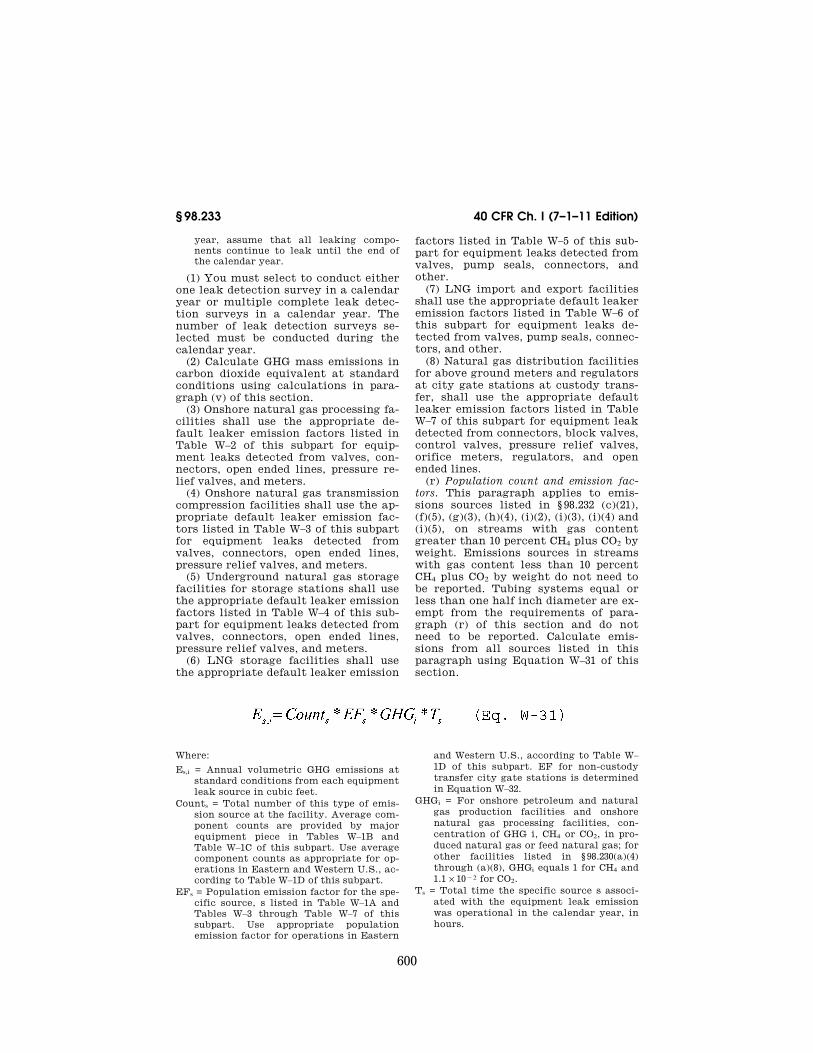
600
40 CFR Ch. I (7–1–11 Edition) § 98.233
year, assume that all leaking compo-nents continue to leak until the end of the calendar year.
(1) You must select to conduct either one leak detection survey in a calendar year or multiple complete leak detec-tion surveys in a calendar year. The number of leak detection surveys se-lected must be conducted during the calendar year.
(2) Calculate GHG mass emissions in carbon dioxide equivalent at standard conditions using calculations in para-graph (v) of this section.
(3) Onshore natural gas processing fa-cilities shall use the appropriate de-fault leaker emission factors listed in Table W–2 of this subpart for equip-ment leaks detected from valves, con-nectors, open ended lines, pressure re-lief valves, and meters.
(4) Onshore natural gas transmission compression facilities shall use the ap-propriate default leaker emission fac-tors listed in Table W–3 of this subpart for equipment leaks detected from valves, connectors, open ended lines, pressure relief valves, and meters.
(5) Underground natural gas storage facilities for storage stations shall use the appropriate default leaker emission factors listed in Table W–4 of this sub-part for equipment leaks detected from valves, connectors, open ended lines, pressure relief valves, and meters.
(6) LNG storage facilities shall use the appropriate default leaker emission
factors listed in Table W–5 of this sub-part for equipment leaks detected from valves, pump seals, connectors, and other.
(7) LNG import and export facilities shall use the appropriate default leaker emission factors listed in Table W–6 of this subpart for equipment leaks de-tected from valves, pump seals, connec-tors, and other.
(8) Natural gas distribution facilities for above ground meters and regulators at city gate stations at custody trans-fer, shall use the appropriate default leaker emission factors listed in Table W–7 of this subpart for equipment leak detected from connectors, block valves, control valves, pressure relief valves, orifice meters, regulators, and open ended lines.
(r) Population count and emission fac-tors. This paragraph applies to emis-sions sources listed in § 98.232 (c)(21), (f)(5), (g)(3), (h)(4), (i)(2), (i)(3), (i)(4) and (i)(5), on streams with gas content greater than 10 percent CH4 plus CO2 by weight. Emissions sources in streams with gas content less than 10 percent CH4 plus CO2 by weight do not need to be reported. Tubing systems equal or less than one half inch diameter are ex-empt from the requirements of para-graph (r) of this section and do not need to be reported. Calculate emis-sions from all sources listed in this paragraph using Equation W–31 of this section.
Where:
Es,i = Annual volumetric GHG emissions at standard conditions from each equipment leak source in cubic feet.
Counts = Total number of this type of emis-sion source at the facility. Average com-ponent counts are provided by major equipment piece in Tables W–1B and Table W–1C of this subpart. Use average component counts as appropriate for op-erations in Eastern and Western U.S., ac-cording to Table W–1D of this subpart.
EFs = Population emission factor for the spe-cific source, s listed in Table W–1A and Tables W–3 through Table W–7 of this subpart. Use appropriate population emission factor for operations in Eastern
and Western U.S., according to Table W– 1D of this subpart. EF for non-custody transfer city gate stations is determined in Equation W–32.
GHGi = For onshore petroleum and natural gas production facilities and onshore natural gas processing facilities, con-centration of GHG i, CH4 or CO2, in pro-duced natural gas or feed natural gas; for other facilities listed in § 98.230(a)(4) through (a)(8), GHGi equals 1 for CH4 and 1.1 × 10¥2 for CO2.
Ts = Total time the specific source s associ-ated with the equipment leak emission was operational in the calendar year, in hours.
VerDate Mar<15>2010 14:18 Sep 30, 2011 Jkt 223164 PO 00000 Frm 00612 Fmt 8010 Sfmt 8002 Y:\SGML\223164.XXX 223164 ER
30N
O10
.201
</G
PH
>
wre
ier-
avile
s on
DS
K7S
PT
VN
1PR
OD
with
CF
R
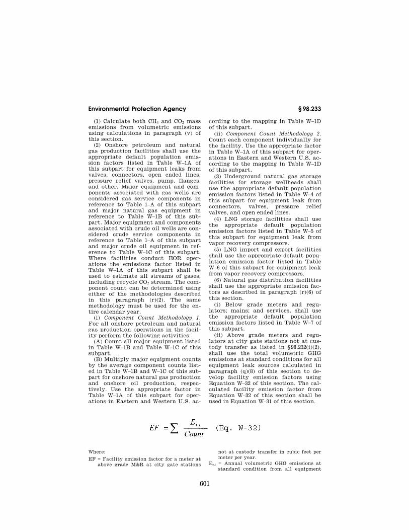
601
Environmental Protection Agency § 98.233
(1) Calculate both CH4 and CO2 mass emissions from volumetric emissions using calculations in paragraph (v) of this section.
(2) Onshore petroleum and natural gas production facilities shall use the appropriate default population emis-sion factors listed in Table W–1A of this subpart for equipment leaks from valves, connectors, open ended lines, pressure relief valves, pump, flanges, and other. Major equipment and com-ponents associated with gas wells are considered gas service components in reference to Table 1–A of this subpart and major natural gas equipment in reference to Table W–1B of this sub-part. Major equipment and components associated with crude oil wells are con-sidered crude service components in reference to Table 1–A of this subpart and major crude oil equipment in ref-erence to Table W–1C of this subpart. Where facilities conduct EOR oper-ations the emissions factor listed in Table W–1A of this subpart shall be used to estimate all streams of gases, including recycle CO2 stream. The com-ponent count can be determined using either of the methodologies described in this paragraph (r)(2). The same methodology must be used for the en-tire calendar year.
(i) Component Count Methodology 1. For all onshore petroleum and natural gas production operations in the facil-ity perform the following activities:
(A) Count all major equipment listed in Table W–1B and Table W–1C of this subpart.
(B) Multiply major equipment counts by the average component counts list-ed in Table W–1B and W–1C of this sub-part for onshore natural gas production and onshore oil production, respec-tively. Use the appropriate factor in Table W–1A of this subpart for oper-ations in Eastern and Western U.S. ac-
cording to the mapping in Table W–1D of this subpart.
(ii) Component Count Methodology 2. Count each component individually for the facility. Use the appropriate factor in Table W–1A of this subpart for oper-ations in Eastern and Western U.S. ac-cording to the mapping in Table W–1D of this subpart.
(3) Underground natural gas storage facilities for storage wellheads shall use the appropriate default population emission factors listed in Table W–4 of this subpart for equipment leak from connectors, valves, pressure relief valves, and open ended lines.
(4) LNG storage facilities shall use the appropriate default population emission factors listed in Table W–5 of this subpart for equipment leak from vapor recovery compressors.
(5) LNG import and export facilities shall use the appropriate default popu-lation emission factor listed in Table W–6 of this subpart for equipment leak from vapor recovery compressors.
(6) Natural gas distribution facilities shall use the appropriate emission fac-tors as described in paragraph (r)(6) of this section.
(i) Below grade meters and regu-lators; mains; and services, shall use the appropriate default population emission factors listed in Table W–7 of this subpart.
(ii) Above grade meters and regu-lators at city gate stations not at cus-tody transfer as listed in § 98.232(i)(2), shall use the total volumetric GHG emissions at standard conditions for all equipment leak sources calculated in paragraph (q)(8) of this section to de-velop facility emission factors using Equation W–32 of this section. The cal-culated facility emission factor from Equation W–32 of this section shall be used in Equation W–31 of this section.
Where:
EF = Facility emission factor for a meter at above grade M&R at city gate stations
not at custody transfer in cubic feet per meter per year.
Es,i = Annual volumetric GHG emissions at standard condition from all equipment
VerDate Mar<15>2010 14:18 Sep 30, 2011 Jkt 223164 PO 00000 Frm 00613 Fmt 8010 Sfmt 8002 Y:\SGML\223164.XXX 223164 ER
30N
O10
.202
</M
AT
H>
wre
ier-
avile
s on
DS
K7S
PT
VN
1PR
OD
with
CF
R

602
40 CFR Ch. I (7–1–11 Edition) § 98.233
leak sources at all above grade M&R city gate stations at custody transfer, from paragraph (q) of this section.
Count = Total number of meter runs at all above grade M&R city gate stations at custody transfer.
(s) Offshore petroleum and natural gas production facilities. Report CO2, CH4, and N2O emissions for offshore petro-leum and natural gas production from all equipment leaks, vented emission, and flare emission source types as iden-tified in the data collection and emis-sions estimation study conducted by BOEMRE in compliance with 30 CFR 250.302 through 304.
(1) Offshore production facilities under BOEMRE jurisdiction shall re-port the same annual emissions as cal-culated and reported by BOEMRE in data collection and emissions esti-mation study published by BOEMRE referenced in 30 CFR 250.302 through 304 (GOADS).
(i) For any calendar year that does not overlap with the most recent BOEMRE emissions study publication year, report the most recent BOEMRE reported emissions data published by BOEMRE referenced in 30 CFR 250.302 through 304 (GOADS). Adjust emissions based on the operating time for the fa-cility relative to the operating time in the most recent BOEMRE published study.
(ii) [Reserved] (2) Offshore production facilities that
are not under BOEMRE jurisdiction shall use monitoring methods and cal-culation methodologies published by BOEMRE referenced in 30 CFR 250.302 through 304 to calculate and report emissions (GOADS).
(i) For any calendar year that does not overlap with the most recent BOEMRE emissions study publication, report the most recent reported emis-sions data with emissions adjusted based on the operating time for the fa-cility relative to operating time in the previous reporting period.
(ii) [Reserved] (3) If BOEMRE discontinues or delays
their data collection effort by more than 4 years, then offshore reporters shall once in every 4 years use the most recent BOEMRE data collection and emissions estimation methods to report emission from the facility sources.
(4) For either first or subsequent year reporting, offshore facilities either within or outside of BOEMRE jurisdic-tion that were not covered in the pre-vious BOEMRE data collection cycle shall use the most recent BOEMRE data collection and emissions esti-mation methods published by BOEMRE referenced in 30 CFR 250.302 through 304 to calculate and report emissions (GOADS) to report emissions.
(t) Volumetric emissions. Calculate vol-umetric emissions at standard condi-tions as specified in paragraphs (t)(1) or (2) of this section determined by engi-neering estimate based on best avail-able data unless otherwise specified.
(1) Calculate natural gas volumetric emissions at standard conditions by converting actual temperature and pressure of natural gas emissions to standard temperature and pressure of natural gas using Equation W–33 of this section.
Where:
Es,n = Natural gas volumetric emissions at standard temperature and pressure (STP) conditions in cubic feet.
Ea,n = Natural gas volumetric emissions at actual conditions in cubic feet.
Ts = Temperature at standard conditions ( °F).
Ta = Temperature at actual emission condi-tions ( °F).
Ps = Absolute pressure at standard condi-tions (psia).
Pa = Absolute pressure at actual conditions (psia).
VerDate Mar<15>2010 14:18 Sep 30, 2011 Jkt 223164 PO 00000 Frm 00614 Fmt 8010 Sfmt 8002 Y:\SGML\223164.XXX 223164 ER
30N
O10
.203
</M
AT
H>
wre
ier-
avile
s on
DS
K7S
PT
VN
1PR
OD
with
CF
R
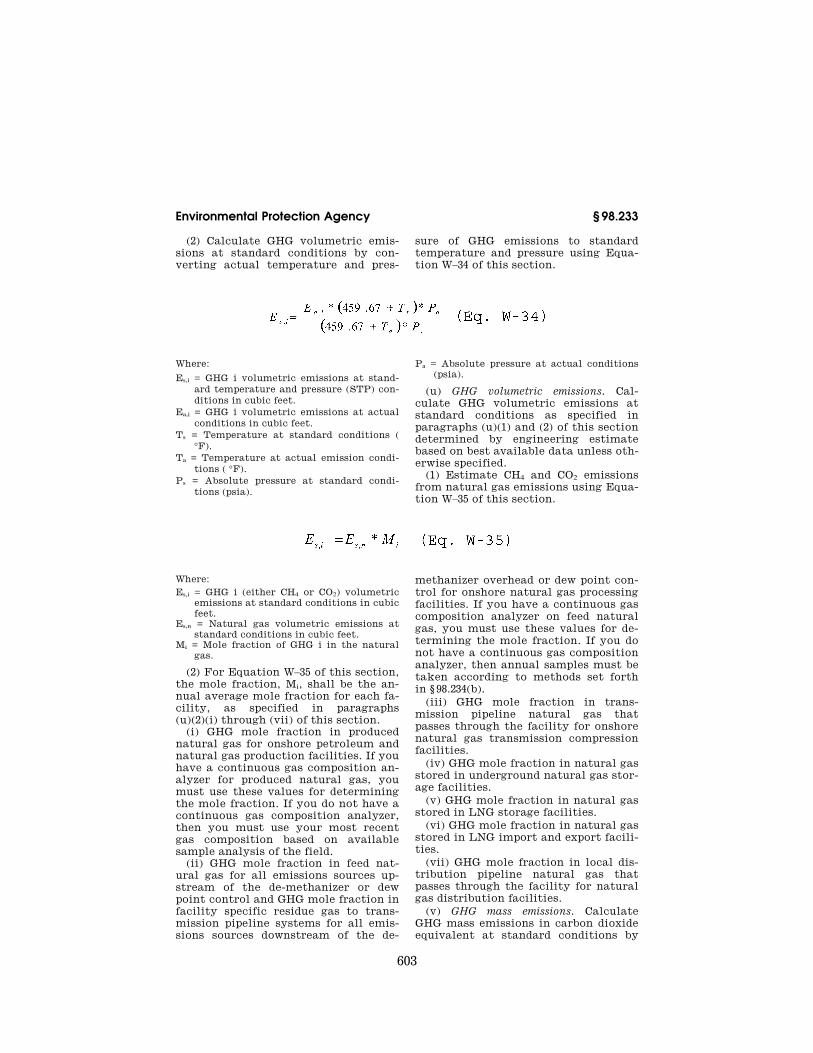
603
Environmental Protection Agency § 98.233
(2) Calculate GHG volumetric emis-sions at standard conditions by con-verting actual temperature and pres-
sure of GHG emissions to standard temperature and pressure using Equa-tion W–34 of this section.
Where:
Es,i = GHG i volumetric emissions at stand-ard temperature and pressure (STP) con-ditions in cubic feet.
Ea,i = GHG i volumetric emissions at actual conditions in cubic feet.
Ts = Temperature at standard conditions ( °F).
Ta = Temperature at actual emission condi-tions ( °F).
Ps = Absolute pressure at standard condi-tions (psia).
Pa = Absolute pressure at actual conditions (psia).
(u) GHG volumetric emissions. Cal-culate GHG volumetric emissions at standard conditions as specified in paragraphs (u)(1) and (2) of this section determined by engineering estimate based on best available data unless oth-erwise specified.
(1) Estimate CH4 and CO2 emissions from natural gas emissions using Equa-tion W–35 of this section.
Where: Es,i = GHG i (either CH4 or CO2) volumetric
emissions at standard conditions in cubic feet.
Es,n = Natural gas volumetric emissions at standard conditions in cubic feet.
Mi = Mole fraction of GHG i in the natural gas.
(2) For Equation W–35 of this section, the mole fraction, Mi, shall be the an-nual average mole fraction for each fa-cility, as specified in paragraphs (u)(2)(i) through (vii) of this section.
(i) GHG mole fraction in produced natural gas for onshore petroleum and natural gas production facilities. If you have a continuous gas composition an-alyzer for produced natural gas, you must use these values for determining the mole fraction. If you do not have a continuous gas composition analyzer, then you must use your most recent gas composition based on available sample analysis of the field.
(ii) GHG mole fraction in feed nat-ural gas for all emissions sources up-stream of the de-methanizer or dew point control and GHG mole fraction in facility specific residue gas to trans-mission pipeline systems for all emis-sions sources downstream of the de-
methanizer overhead or dew point con-trol for onshore natural gas processing facilities. If you have a continuous gas composition analyzer on feed natural gas, you must use these values for de-termining the mole fraction. If you do not have a continuous gas composition analyzer, then annual samples must be taken according to methods set forth in § 98.234(b).
(iii) GHG mole fraction in trans-mission pipeline natural gas that passes through the facility for onshore natural gas transmission compression facilities.
(iv) GHG mole fraction in natural gas stored in underground natural gas stor-age facilities.
(v) GHG mole fraction in natural gas stored in LNG storage facilities.
(vi) GHG mole fraction in natural gas stored in LNG import and export facili-ties.
(vii) GHG mole fraction in local dis-tribution pipeline natural gas that passes through the facility for natural gas distribution facilities.
(v) GHG mass emissions. Calculate GHG mass emissions in carbon dioxide equivalent at standard conditions by
VerDate Mar<15>2010 14:18 Sep 30, 2011 Jkt 223164 PO 00000 Frm 00615 Fmt 8010 Sfmt 8002 Y:\SGML\223164.XXX 223164 ER
30N
O10
.204
</M
AT
H>
ER
30N
O10
.205
</M
AT
H>
wre
ier-
avile
s on
DS
K7S
PT
VN
1PR
OD
with
CF
R
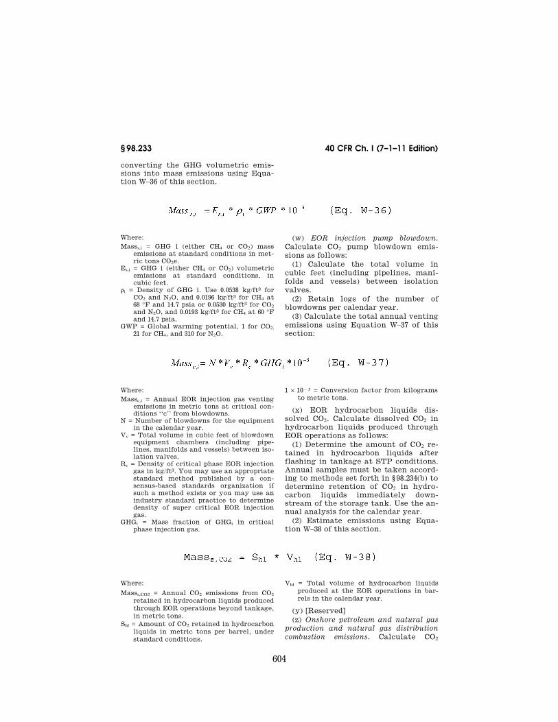
604
40 CFR Ch. I (7–1–11 Edition) § 98.233
converting the GHG volumetric emis-sions into mass emissions using Equa-tion W–36 of this section.
Where: Masss,i = GHG i (either CH4 or CO2) mass
emissions at standard conditions in met-ric tons CO2e.
Es,i = GHG i (either CH4 or CO2) volumetric emissions at standard conditions, in cubic feet.
ri = Density of GHG i. Use 0.0538 kg/ft3 for CO2 and N2O, and 0.0196 kg/ft3 for CH4 at 68 °F and 14.7 psia or 0.0530 kg/ft3 for CO2 and N2O, and 0.0193 kg/ft3 for CH4 at 60 °F and 14.7 psia.
GWP = Global warming potential, 1 for CO2, 21 for CH4, and 310 for N2O.
(w) EOR injection pump blowdown. Calculate CO2 pump blowdown emis-sions as follows:
(1) Calculate the total volume in cubic feet (including pipelines, mani-folds and vessels) between isolation valves.
(2) Retain logs of the number of blowdowns per calendar year.
(3) Calculate the total annual venting emissions using Equation W–37 of this section:
Where: Massc,i = Annual EOR injection gas venting
emissions in metric tons at critical con-ditions ‘‘c’’ from blowdowns.
N = Number of blowdowns for the equipment in the calendar year.
Vv = Total volume in cubic feet of blowdown equipment chambers (including pipe-lines, manifolds and vessels) between iso-lation valves.
Rc = Density of critical phase EOR injection gas in kg/ft3. You may use an appropriate standard method published by a con-sensus-based standards organization if such a method exists or you may use an industry standard practice to determine density of super critical EOR injection gas.
GHGi = Mass fraction of GHGi in critical phase injection gas.
1 × 10¥3 = Conversion factor from kilograms to metric tons.
(x) EOR hydrocarbon liquids dis-solved CO2. Calculate dissolved CO2 in hydrocarbon liquids produced through EOR operations as follows:
(1) Determine the amount of CO2 re-tained in hydrocarbon liquids after flashing in tankage at STP conditions. Annual samples must be taken accord-ing to methods set forth in § 98.234(b) to determine retention of CO2 in hydro-carbon liquids immediately down-stream of the storage tank. Use the an-nual analysis for the calendar year.
(2) Estimate emissions using Equa-tion W–38 of this section.
Where:
Masss,CO2 = Annual CO2 emissions from CO2 retained in hydrocarbon liquids produced through EOR operations beyond tankage, in metric tons.
Shl = Amount of CO2 retained in hydrocarbon liquids in metric tons per barrel, under standard conditions.
Vhl = Total volume of hydrocarbon liquids produced at the EOR operations in bar-rels in the calendar year.
(y) [Reserved] (z) Onshore petroleum and natural gas
production and natural gas distribution combustion emissions. Calculate CO2
VerDate Mar<15>2010 14:18 Sep 30, 2011 Jkt 223164 PO 00000 Frm 00616 Fmt 8010 Sfmt 8002 Y:\SGML\223164.XXX 223164 ER
30N
O10
.206
</M
AT
H>
ER
30N
O10
.207
</M
AT
H>
ER
30N
O10
.208
</M
AT
H>
wre
ier-
avile
s on
DS
K7S
PT
VN
1PR
OD
with
CF
R

605
Environmental Protection Agency § 98.233
CH4,and N2O combustion-related emis-sions from stationary or portable equipment as follows:
(1) If the fuel combusted in the sta-tionary or portable equipment is listed in Table C–1 of subpart C of this part, or is a blend of fuels listed in Table C– 1, use the Tier 1 methodology described in subpart C of this part (General Sta-tionary Fuel Combustion Sources). If the fuel combusted is natural gas and is pipeline quality and has a minimum high heat value of 950 Btu per standard cubic foot, then the natural gas emis-sion factor and high heat values listed in Tables C–1 and C–2 of this part may be used.
(2) For fuel combustion units that combust field gas or process vent gas, or any blend of field gas or process vent gas and fuels listed in Table C–1 of sub-part C of this part, calculate combus-tion emissions as follows:
(i) If you have a continuous flow meter on the combustion unit, you must use the measured flow volumes to
calculate the total flow of gas to the unit. If you do not have a permanent flow meter on the combustion unit, you may install a permanent flow meter on the combustion unit, or use company records or engineering cal-culations based on best available data on heat duty or horsepower to estimate volumetric unit gas flow.
(ii) If you have a continuous gas com-position analyzer on fuel to the com-bustion unit, you must use these com-positions for determining the con-centration of gas hydrocarbon con-stituent in the flow of gas to the unit. If you do not have a continuous gas composition analyzer on gas to the combustion unit, you must use the ap-propriate gas compositions for each stream of hydrocarbons going to the combustion unit as specified in para-graph (u)(2)(i) of this section.
(iii) Calculate GHG volumetric emis-sions at actual conditions using Equa-tions W–39 of this section.
Where: Ea,CO2 = Contribution of annual emissions
from portable or stationary fuel combus-tion sources in cubic feet, under actual conditions.
Va = Volume of gas sent to combustion unit in cubic feet, during the year.
Yj = Concentration of gas hydrocarbon con-stituents j (such as methane, ethane, pro-pane, butane, and pentanes plus).
Rj = Number of carbon atoms in the gas hy-drocarbon constituent j; 1 for methane, 2 for ethane, 3 for propane, 4 for butane, and 5 for pentanes plus).
(3) External fuel combustion sources with a rated heat capacity equal to or
less than 5 mmBtu/hr do not need to re-port combustion emissions. You must report the type and number of each ex-ternal fuel combustion unit.
(4) Calculate GHG volumetric emis-sions at standard conditions using cal-culations in paragraph (t) of this sec-tion.
(5) Calculate both combustion-re-lated CH4 and CO2 mass emissions from volumetric CH4 and CO2 emissions using calculation in paragraph (v) of this section.
(6) Calculate N2O mass emissions using Equation W–40 of this section.
Where:
N2O = Annual N2O emissions from the com-bustion of a particular type of fuel (met-ric tons).
Fuel = Mass or volume of the fuel combusted (mass or volume per year, choose appro-priately to be consistent with the units of HHV).
VerDate Mar<15>2010 14:18 Sep 30, 2011 Jkt 223164 PO 00000 Frm 00617 Fmt 8010 Sfmt 8002 Y:\SGML\223164.XXX 223164 ER
30N
O10
.209
</M
AT
H>
ER
30N
O10
.210
</M
AT
H>
wre
ier-
avile
s on
DS
K7S
PT
VN
1PR
OD
with
CF
R

606
40 CFR Ch. I (7–1–11 Edition) § 98.234
HHV = High heat value of the fuel from para-graphs (z)(8)(i), (z)(8)(ii) or (z)(8)(iii) of this section (units must be consistent with Fuel).
EF = Use 1.0 × 10¥4 kg N2O/mmBtu. 1 × 10¥3 = Conversion factor from kilograms
to metric tons.
(i) For fuels listed in Table C–1 of subpart C of this part, use the provided default HHV in the table.
(ii) For field gas or process vent gas, use 1.235 × 10¥3 mmBtu/scf for HHV.
(iii) For fuels not listed in Table C–1 of subpart C of this part and not field gas or process vent gas, you must use the methodology set forth in the Tier 2 methodology described in subpart C of this part to determine HHV.
§ 98.234 Monitoring and QA/QC re-quirements.
The GHG emissions data for petro-leum and natural gas emissions sources must be quality assured as applicable as specified in this section. Offshore pe-troleum and natural gas production fa-cilities shall adhere to the monitoring and QA/QC requirements as set forth in 30 CFR 250.
(a) You must use any of the methods described as follows in this paragraph to conduct leak detection(s) of equip-ment leaks and through-valve leakage from all source types listed in § 98.233(k), (o), (p) and (q) that occur during a calendar year, except as pro-vided in paragraph (a)(4) of this sec-tion.
(1) Optical gas imaging instrument. Use an optical gas imaging instrument for equipment leak detection in accord-ance with 40 CFR part 60, subpart A, § 60.18(i)(1) and (2) of the Alternative work practice for monitoring equipment leaks. Any emissions detected by the optical gas imaging instrument is a leak unless screened with Method 21 (40 CFR part 60, appendix A–7) monitoring, in which case 10,000 ppm or greater is designated a leak. In addition, you must operate the optical gas imaging instrument to image the source types required by this subpart in accordance with the instrument manufacturer’s operating parameters.
(2) Method 21. Use the equipment leak detection methods in 40 CFR part 60, appendix A–7, Method 21. If using Meth-od 21 monitoring, if an instrument reading of 10,000 ppm or greater is
measured, a leak is detected. Inacces-sible emissions sources, as defined in 40 CFR part 60, are not exempt from this subpart. Owners or operators must use alternative leak detection devices as described in paragraph(a)(1) of this sec-tion to monitor inaccessible equipment leaks or vented emissions.
(3) Infrared laser beam illuminated in-strument. Use an infrared laser beam il-luminated instrument for equipment leak detection. Any emissions detected by the infrared laser beam illuminated instrument is a leak unless screened with Method 21 monitoring, in which case 10,000 ppm or greater is designated a leak. In addition, you must operate the infrared laser beam illuminated in-strument to detect the source types re-quired by this subpart in accordance with the instrument manufacturer’s operating parameters.
(4) Optical gas imaging instrument. An optical gas imaging instrument must be used for all source types that are in-accessible and cannot be monitored without elevating the monitoring per-sonnel more than 2 meters above a sup-port surface.
(5) Acoustic leak detection device. Use the acoustic leak detection device to detect through-valve leakage. When using the acoustic leak detection de-vice to quantify the through-valve leakage, you must use the instrument manufacturer’s calculation methods to quantify the through-valve leak. When using the acoustic leak detection de-vice, if a leak of 3.1 scf per hour or greater is calculated, a leak is de-tected. In addition, you must operate the acoustic leak detection device to monitor the source valves required by this subpart in accordance with the in-strument manufacturer’s operating pa-rameters.
(b) You must operate and calibrate all flow meters, composition analyzers and pressure gauges used to measure quantities reported in § 98.233 according to the procedures in § 98.3(i) and the procedures in paragraph (b) of this sec-tion. You may use an appropriate standard method published by a con-sensus-based standards organization if such a method exists or you may use an industry standard practice. Con-sensus-based standards organizations
VerDate Mar<15>2010 14:18 Sep 30, 2011 Jkt 223164 PO 00000 Frm 00618 Fmt 8010 Sfmt 8002 Y:\SGML\223164.XXX 223164wre
ier-
avile
s on
DS
K7S
PT
VN
1PR
OD
with
CF
R
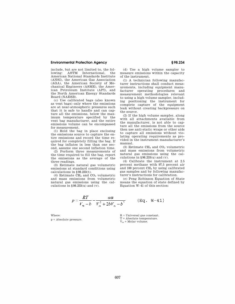
607
Environmental Protection Agency § 98.234
include, but are not limited to, the fol-lowing: ASTM International, the American National Standards Institute (ANSI), the American Gas Association (AGA), the American Society of Me-chanical Engineers (ASME), the Amer-ican Petroleum Institute (API), and the North American Energy Standards Board (NAESB).
(c) Use calibrated bags (also known as vent bags) only where the emissions are at near-atmospheric pressures such that it is safe to handle and can cap-ture all the emissions, below the max-imum temperature specified by the vent bag manufacturer, and the entire emissions volume can be encompassed for measurement.
(1) Hold the bag in place enclosing the emissions source to capture the en-tire emissions and record the time re-quired for completely filling the bag. If the bag inflates in less than one sec-ond, assume one second inflation time.
(2) Perform three measurements of the time required to fill the bag, report the emissions as the average of the three readings.
(3) Estimate natural gas volumetric emissions at standard conditions using calculations in § 98.233(t).
(4) Estimate CH4 and CO2 volumetric and mass emissions from volumetric natural gas emissions using the cal-culations in § 98.233(u) and (v).
(d) Use a high volume sampler to measure emissions within the capacity of the instrument.
(1) A technician following manufac-turer instructions shall conduct meas-urements, including equipment manu-facturer operating procedures and measurement methodologies relevant to using a high volume sampler, includ-ing positioning the instrument for complete capture of the equipment leak without creating backpressure on the source.
(2) If the high volume sampler, along with all attachments available from the manufacturer, is not able to cap-ture all the emissions from the source then use anti-static wraps or other aids to capture all emissions without vio-lating operating requirements as pro-vided in the instrument manufacturer’s manual.
(3) Estimate CH4 and CO2 volumetric and mass emissions from volumetric natural gas emissions using the cal-culations in § 98.233(u) and (v).
(4) Calibrate the instrument at 2.5 percent methane with 97.5 percent air and 100 percent CH4 by using calibrated gas samples and by following manufac-turer’s instructions for calibration.
(e) Peng Robinson Equation of State means the equation of state defined by Equation W–41 of this section:
Where:
p = Absolute pressure.
R = Universal gas constant. T = Absolute temperature. Vm = Molar volume.
VerDate Mar<15>2010 14:18 Sep 30, 2011 Jkt 223164 PO 00000 Frm 00619 Fmt 8010 Sfmt 8002 Y:\SGML\223164.XXX 223164 ER
30N
O10
.211
</M
AT
H>
wre
ier-
avile
s on
DS
K7S
PT
VN
1PR
OD
with
CF
R

608
40 CFR Ch. I (7–1–11 Edition) § 98.234
Where: w = Acentric factor of the species. Tc = Critical temperature. Pc = Critical pressure.
(f) Special reporting provisions (1) Best available monitoring methods.
EPA will allow owners or operators to use best available monitoring methods for parameters in § 98.233 Calculating GHG Emissions as specified in para-graphs (f)(2), (f)(3), and (f)(4) of this sec-tion. If the reporter anticipates the po-tential need for best available moni-toring for sources for which they need to petition EPA and the situation is unresolved at the time of the deadline, reporters should submit written notice of this potential situation to EPA by the specified deadline for requests to be considered. EPA reserves the right to review petitions after the deadline but will only consider and approve late pe-titions which demonstrate extreme or unusual circumstances. The Adminis-trator reserves to right to request fur-ther information in regard to all peti-tion requests. The owner or operator must use the calculation methodolo-gies and equations in § 98.233 Calcu-lating GHG Emissions. Best available monitoring methods means any of the following methods specified in para-graph (f)(1) of this section:
(i) Monitoring methods currently used by the facility that do not meet the specifications of this subpart.
(ii) Supplier data. (iii) Engineering calculations. (iv) Other company records. (2) Best available monitoring methods
for well-related emissions. During Janu-ary 1, 2011 through September 30, 2011,
owners and operators may use best available monitoring methods for any well-related data that cannot reason-ably be measured according to the monitoring and QA/QC requirements of this subpart, and only where required measurements cannot be duplicated due to technical limitations after Sep-tember 30, 2011. These well-related sources are:
(i) Gas well venting during well com-pletions and workovers with hydraulic fracturing as specified in § 98.233(g).
(ii) Well testing venting and flaring as specified in § 98.233(l).
(3) Best available monitoring methods for specified activity data. During Janu-ary 1, 2011 through September 30, 2011, owners or operators may use best available monitoring methods for ac-tivity data as listed below that cannot reasonably be obtained according to the monitoring and QA/QC require-ments of this subpart, specifically for events that generate data that can be collected only between January 1, 2011 and September 30, 2011 and cannot be duplicated after September 30, 2011. These sources are:
(i) Cumulative hours of venting, days, or times of operation in § 98.233(e), (f), (g), (h), (l), (o), (p), (q), and (r).
(ii) Number of blowdowns, comple-tions, workovers, or other events in § 98.233(f), (g), (h), (i), and (w).
(iii) Cumulative volume produced, volume input or output, or volume of fuel used in paragraphs § 98.233(d), (e), (j), (k), (l), (m), (n), (x), (y), and (z).
(4) Best available monitoring methods for leak detection and measurement. The
VerDate Mar<15>2010 14:18 Sep 30, 2011 Jkt 223164 PO 00000 Frm 00620 Fmt 8010 Sfmt 8002 Y:\SGML\223164.XXX 223164 ER
30N
O10
.212
</M
AT
H>
wre
ier-
avile
s on
DS
K7S
PT
VN
1PR
OD
with
CF
R

609
Environmental Protection Agency § 98.234
owner or operator may request use of best available monitoring methods be-tween January 1, 2011 and December 31, 2011 for sources requiring leak detec-tion and/or measurement. These sources include:
(i) Reciprocating compressor rod packing venting in onshore natural gas processing, onshore natural gas trans-mission compression, underground nat-ural gas storage, LNG storage, and LNG import and export equipment as specified in § 98.232(d)(1), (e)(1), (f)(1), (g)(1), and (h)(1).
(ii) Centrifugal compressor wet seal oil degassing venting in onshore nat-ural gas processing, onshore natural gas transmission compression, under-ground natural gas storage, LNG stor-age, and LNG import and export equip-ment as specified in § 98.232(d)(2), (e)(2), (f)(2), (g)(2), and (h)(2).
(iii) Acid gas removal vent stacks in onshore petroleum and natural gas pro-duction and onshore natural gas proc-essing as specified in § 98.232(c)(17) and (d)(6).
(iv) Equipment leak emissions from valves, connectors, open ended lines, pressure relief valves, block valves, control valves, compressor blowdown valves, orifice meters, other meters, regulators, vapor recovery compres-sors, centrifugal compressor dry seals, and/or other equipment leaks in on-shore natural gas processing, onshore natural gas transmission compression, underground natural gas storage, LNG storage, LNG import and export equip-ment, and natural gas distribution as specified in § 98.232(d)(7), (e)(7), (f)(5), (g)(3), (h)(4), and (i)(1).
(v) Condensate (oil and/or water) storage tanks in onshore natural gas transmission compression as specified in § 98.232(e)(3).
(5) Requests for the use of best available monitoring methods. The owner or oper-ator may submit a request to the Ad-ministrator to use one or more best available monitoring methods.
(i) No request or approval by the Ad-ministrator is necessary to use best available monitoring methods between January 1, 2011 and September 30, 2011 for the sources specified in paragraph (f)(2) of this section.
(ii) No request or approval by the Ad-ministrator is necessary to use best
available monitoring methods between January 1, 2011 and September 30, 2011 for sources specified in paragraph (f)(3) of this section.
(iii) Owners or operators must submit a request and receive approval by the Administrator to use best available monitoring methods between January 1, 2011 and December 31, 2011 for sources specified in paragraph (f)(4) of this sec-tion.
(A) Timing of Request. The request to use best available monitoring methods for paragraph (f)(4) of this section must be submitted to EPA no later than July 31, 2011.
(B) Content of request. Requests must contain the following information for sources listed in paragraph (f)(4) of this section:
(1) A list of specific source types and specific equipment, monitoring instru-mentation, and/or services for which the request is being made and the loca-tions where each piece of monitoring instrumentation will be installed or monitoring service will be supplied.
(2) Identification of the specific rule requirements (by subpart, section, and paragraph number) for which the in-strumentation or monitoring service is needed.
(3) Documentation which dem-onstrates that the owner or operator made all reasonable efforts to obtain the information, services or equipment necessary to comply with subpart W re-porting requirements, including evi-dence of specific service or equipment providers contacted and why services or information could not be obtained during 2011.
(4) A description of the specific ac-tions the facility will take to obtain and/or install the equipment or obtain the monitoring service as soon as rea-sonably feasible and the expected date by which the equipment will be ob-tained and operating or service will be provided.
(C) Approval criteria. To obtain ap-proval, the owner or operator must demonstrate to the Administrator’s satisfaction that it does not own the required monitoring equipment, and it is not reasonably feasible to acquire, install, and operate a required piece of monitoring equipment or to obtain
VerDate Mar<15>2010 14:18 Sep 30, 2011 Jkt 223164 PO 00000 Frm 00621 Fmt 8010 Sfmt 8002 Y:\SGML\223164.XXX 223164wre
ier-
avile
s on
DS
K7S
PT
VN
1PR
OD
with
CF
R

610
40 CFR Ch. I (7–1–11 Edition) § 98.234
leak detection or measurement serv-ices in order to meet the requirements of this subpart for 2011.
(iv) EPA does not anticipate a need to approve the use of best available monitoring methods for sources not listed in paragraphs(f)(2), (f)(3), and (f)(4) of this section; however, EPA will review such requests if submitted in accordance with paragraph (f)(5)(iv)(A)–(C) of this section.
(A) Timing of Request. The request to use best available monitoring methods for sources not listed in paragraph (f)(2), (f)(3), and (f)(4) of this section must be submitted to EPA no later than July 31, 2011.
(B) Content of request. Requests must contain the following information:
(1) A list of specific source categories and parameters for which the owner or operator is seeking use of best avail-able monitoring methods.
(2) A description of the data collec-tion methodologies that do not meet safety regulations, technical infeasi-bility, or specific laws or regulations that conflict with each specific source for which an owner or operator is re-questing use of best available moni-toring methodologies.
(3) A detailed explanation and sup-porting documentation of how and when the owner or operator will re-ceive the services or equipment to comply with all subpart W reporting requirements.
(C) Approval criteria. To obtain ap-proval, the owner or operator must demonstrate to the Administrator’s satisfaction that the owner or operator faces unique safety, technical or legal issues rendering them unable to meet the requirements of this subpart for 2011.
(6) Requests for extension of the use of best available monitoring methods through December 31, 2011 for sources in paragraph (f)(2) of this section. The owner or operator may submit a re-quest to the Administrator to use one or more best available monitoring methods described in paragraph (f)(2) of this section beyond September 30, 2011.
(i) Timing of Request. The extension request must be submitted to EPA no later than July 31, 2011.
(ii) Content of request. Requests must contain the following information:
(A) A list of specific source types and specific equipment, monitoring instru-mentation, contract modifications, and/or services for which the request is being made and the locations where each piece of monitoring instrumenta-tion will be installed, monitoring serv-ice will be supplied, or contracts will be modified.
(B) Identification of the specific rule requirements (by subpart, section, and paragraph number) for which the in-strumentation, contract modification, or monitoring service is needed.
(C) A description and applicable cor-respondence outlining the diligent ef-forts of the owner or operator in ob-taining the needed equipment or serv-ice and why they could not be obtained and installed in a period of time ena-bling completion of applicable require-ments of this subpart within the 2011 calendar year.
(D) If the reason for the extension is that the owner or operator cannot col-lect data from a service provider or rel-evant organization in order for the owner or operator to meet require-ments of this subpart for the 2011 cal-endar year, the owner or operator must demonstrate a good faith effort that it is not possible to obtain the necessary information, service or hardware which may include providing correspondence from specific service providers or other relevant entities to the owner or oper-ator, whereby the service provider states that it is unable to provide the necessary data or services requested by the owner or operator that would en-able the owner or operator to comply with subpart W reporting requirements by September 30, 2011.
(E) A description of the specific ac-tions the owner or operator will take to comply with monitoring require-ments in 2012 and beyond.
(iii) Approval criteria. To obtain ap-proval, the owner or operator must demonstrate to the Administrator’s satisfaction that it is not reasonably feasible to obtain the data necessary to meet the requirements of this subpart for the sources specified in paragraph (f)(2) of this section by September 30, 2011.
(7) Requests for extension of the use of best available monitoring methods through December 31, 2011 for sources in
VerDate Mar<15>2010 14:18 Sep 30, 2011 Jkt 223164 PO 00000 Frm 00622 Fmt 8010 Sfmt 8002 Y:\SGML\223164.XXX 223164wre
ier-
avile
s on
DS
K7S
PT
VN
1PR
OD
with
CF
R

611
Environmental Protection Agency § 98.235
paragraph (f)(3) of this section. The owner or operator may submit a re-quest to the Administrator to use one or more best available monitoring methods described in paragraph (f)(3) of this section beyond September 30, 2011.
(i) Timing of request. The extension re-quest must be submitted to EPA no later than July 31, 2011.
(ii) Content of request. Requests must contain the following information:
(A) A list of specific source types for which data collection could not be im-plemented.
(B) Identification of the specific rule requirements (by subpart, section, and paragraph number) for which the data collection could not be implemented.
(C) A description of the data collec-tion methodologies that do not meet safety regulations, technical infeasi-bility, or specific laws or regulations that conflict with each specific source for which an owner or operator is re-questing use of best available moni-toring methodologies for which data collection could not be implemented in the 2011 calendar year.
(iii) Approval criteria. To obtain ap-proval, the owner or operator must demonstrate to the Administrator’s satisfaction that is not reasonably fea-sible to implement the data collection for the sources described in paragraph (f)(3) of this section for the methods re-quired in this subpart by September 30, 2011.
(8) Requests for extension of the use of best available monitoring methods beyond 2011 for sources listed in paragraphs (f)(2), (f)(3), (f)(4), (f)(5)(iv) of this section and other sources in this subpart. EPA does not anticipate a need for approv-ing the use of best available methods beyond December 31, 2011, except in ex-treme circumstances, which include safety, a requirement being technically infeasible or counter to other local, State, or Federal regulations.
(i) Timing of request. The request to use best available monitoring methods for paragraphs (f)(2), (f)(3), (f)(4), (f)(5)(iv) of this section and sources not listed in paragraphs (f)(2), (f)(3), (f)(4), (f)(5)(iv) of this section must be sub-mitted to EPA no later than Sep-tember 30, 2011.
(ii) Content of request. Requests must contain the following information:
(iii) A list of specific source cat-egories and parameters for which the owner or operator is seeking use of best available monitoring methods.
(iv) A description of the data collec-tion methodologies that do not meet safety regulations, technical infeasi-bility, or specific laws or regulations that conflict with each specific source for which an owner or operator is re-questing use of best available moni-toring methodologies.
(v) A detailed explanation and sup-porting documentation of how and when the owner or operator will re-ceive the services or equipment to comply with all of this subpart W re-porting requirements.
(C) Approval criteria. To obtain ap-proval, the owner or operator must demonstrate to the Administrator’s satisfaction that the owner or operator faces unique safety, technical or legal issues rendering them unable to meet the requirements of this subpart.
[75 FR 74488, Nov. 30, 2010, as amended at 76 FR 22827, Apr. 25, 2011]
§ 98.235 Procedures for estimating missing data.
A complete record of all estimated and/or measured parameters used in the GHG emissions calculations is re-quired. If data are lost or an error oc-curs during annual emissions esti-mation or measurements, you must re-peat the estimation or measurement activity for those sources as soon as possible, including in the subsequent calendar year if missing data are not discovered until after December 31 of the year in which data are collected, until valid data for reporting is ob-tained. Data developed and/or collected in a subsequent calendar year to sub-stitute for missing data cannot be used for that subsequent year’s emissions estimation. Where missing data proce-dures are used for the previous year, at least 30 days must separate emissions estimation or measurements for the previous year and emissions estimation or measurements for the current year of data collection. For missing data which are continuously monitored or measured, (for example flow meters), or for missing temperature or pressure data that are required under § 98.236, the reporter may use best available
VerDate Mar<15>2010 14:18 Sep 30, 2011 Jkt 223164 PO 00000 Frm 00623 Fmt 8010 Sfmt 8002 Y:\SGML\223164.XXX 223164wre
ier-
avile
s on
DS
K7S
PT
VN
1PR
OD
with
CF
R

612
40 CFR Ch. I (7–1–11 Edition) § 98.236
data for use in emissions determina-tions. The reporter must record and re-port the basis for the best available data in these cases.
§ 98.236 Data reporting requirements. In addition to the information re-
quired by § 98.3(c), each annual report must contain reported emissions and related information as specified in this section.
(a) Report annual emissions sepa-rately for each of the industry seg-ments listed in paragraphs (a)(1) through (8) of this section in metric tons CO2e per year at standard condi-tions. For each segment, report emis-sions from each source type § 98.232(a) in the aggregate, unless specified oth-erwise. For example, an onshore nat-ural gas production operation with multiple reciprocating compressors must report emissions from all recipro-cating compressors as an aggregate number.
(1) Onshore petroleum and natural gas production.
(2) Offshore petroleum and natural gas production.
(3) Onshore natural gas processing. (4) Onshore natural gas transmission
compression. (5) Underground natural gas storage. (6) LNG storage. (7) LNG import and export. (8) Natural gas distribution. Report
each source in the aggregate for pipe-lines and for Metering and Regulating (M&R) stations.
(b) Offshore petroleum and natural gas production is not required to report activity data and emissions for each aggregated source under § 98.236(c). Re-porting requirements for offshore pe-troleum and natural gas production is set forth by BOEMRE in compliance with 30 CFR 250.302 through 304.
(c) For each aggregated source, un-less otherwise specified, report activity data and emissions (in metric tons CO2e per year at standard conditions) for each aggregated source type as fol-lows:
(1) For natural gas pneumatic devices (refer to Equation W–1 of § 98.233), re-port the following:
(i) Actual count and estimated count separately of natural gas pneumatic high bleed devices as applicable.
(ii) Actual count and estimated count separately of natural gas pneumatic low bleed devices as applicable.
(iii) Actual count and estimated count separately of natural gas pneu-matic intermittent bleed devices as ap-plicable.
(iv) Report emissions collectively. (2) For natural gas driven pneumatic
pumps (refer to Equation W–2 of § 98.233), report the following,
(i) Count of natural gas driven pneu-matic pumps.
(ii) Report emissions collectively. (3) For each acid gas removal unit
(refer to Equation W–3 and Equation W–4 of § 98.233), report the following:
(i) Total throughput off the acid gas removal unit using a meter or engi-neering estimate based on process knowledge or best available data in million cubic feet per year.
(ii) For Calculation Methodology 1 and Calculation Methodology 2 of § 98.233(d), fraction of CO2 content in the vent from the acid gas removal unit (refer to § 98.233(d)(6)).
(iii) For Calculation Methodology 3 of § 98.233(d), volume fraction of CO2 content of natural gas into and out of the acid gas removal unit (refer to § 98.233(d)(7) and (d)(8)).
(iv) Report emissions from the AGR unit recovered and transferred outside the facility.
(v) Report emissions individually. (4) For dehydrators, report the fol-
lowing: (i) For each Glycol dehydrator with a
throughput greater than or equal to 0.4 MMscfd (refer to § 98.233(e)(1)), report the following:
(A) Glycol dehydrator feed natural gas flow rate in MMscfd, determined by engineering estimate based on best available data.
(B) Glycol dehydrator absorbent cir-culation pump type.
(C) Whether stripper gas is used in glycol dehydrator.
(D) Whether a flash tank separator is used in glycol dehydrator.
(E) Type of absorbent. (F) Total time the glycol dehydrator
is operating in hours. (G) Temperature, in degrees Fahr-
enheit and pressure, in psig, of the wet natural gas.
VerDate Mar<15>2010 14:18 Sep 30, 2011 Jkt 223164 PO 00000 Frm 00624 Fmt 8010 Sfmt 8002 Y:\SGML\223164.XXX 223164wre
ier-
avile
s on
DS
K7S
PT
VN
1PR
OD
with
CF
R

613
Environmental Protection Agency § 98.236
(H) Concentration of CH4 and CO2 in natural gas.
(I) What vent gas controls are used (refer to § 98.233(e)(3) and (e)(4)).
(J) Report vent and flared emissions individually.
(ii) For all glycol dehydrators with a throughput less than 0.4 MMscfd (refer to § 98.233, Equation W–5 of § 98.233), re-port the following:
(A) Count of glycol dehydrators. (B) Whether any vent gas controls
are used (refer to § 98.233(e)(3) and (e)(4)).
(C) Report vent emissions collec-tively.
(iii) For absorbent desiccant dehydrators (refer to Equation W–6 of § 98.233), report the following:
(A) Count of desiccant dehydrators. (B) Report emissions collectively. (5) For well venting for liquids un-
loading (refer to Equations W–7, W–8 and W–9 of § 98.233), report the fol-lowing by field:
(i) Count of wells vented to the at-mosphere for liquids unloading.
(ii) Count of plunger lifts. (iii) Cumulative number of
unloadings vented to the atmosphere. (iv) Average flow rate of the meas-
ured well venting in cubic feet per hour (refer to § 98.233(f)(1)(i)(A)).
(v) Average casing diameter in inches.
(vi) Report emissions collectively. (6) For well completions and
workovers, report the following for each field:
(i) For gas well completions and workovers with hydraulic fracturing (refer to Equation W–10 of § 98.233):
(A) Total count of completions in cal-endar year.
(B) Average flow rate of the meas-ured well completion venting in cubic feet per hour (refer to § 98.233(g)(1)(i) or (g)(1)(ii)).
(C) Total count of workovers in cal-endar year.
(D) Average flow rate of the meas-ured well workover venting in cubic feet per hour (refer to § 98.233(g)(1)(i) or (g)(1)(ii)).
(E) Total number of days of gas vent-ing to the atmosphere during backflow for completion.
(F) Total number of days of gas vent-ing to the atmosphere during backflow for workovers.
(G) Report number of completions and workovers employing reduced emissions completions and engineering estimate based on best available data of the amount of gas recovered to sales.
(H) Report vent emissions collec-tively. Report flared emissions collec-tively.
(ii) For gas well completions and workovers without hydraulic frac-turing (refer to Equation W–13 of § 98.233):
(A) Total count of completions in cal-endar year.
(B) Total count of workovers in cal-endar year.
(C) Total number of days of gas vent-ing to the atmosphere during backflow for completion.
(D) Report vent emissions collec-tively. Report flared emissions collec-tively.
(7) For each blowdown vent stack (refer to Equation W–14 of § 98.233), re-port the following:
(i) Total number of blowdowns per equipment type in calendar year.
(ii) Report emissions collectively per equipment type.
(8) For gas emitted from produced oil sent to atmospheric tanks:
(i) For wellhead gas-liquid separator with oil throughput greater than or equal to 10 barrels per day, using Cal-culation Methodology 1 and 2 of § 98.233(j), report the following by field:
(A) Number of wellhead separators sending oil to atmospheric tanks.
(B) Estimated average separator tem-perature, in degrees Fahrenheit, and estimated average pressure, in psig.
(C) Estimated average sales oil sta-bilized API gravity, in degrees.
(D) Count of hydrocarbon tanks at well pads.
(E) Best estimate of count of stock tanks not at well pads receiving your oil.
(F) Total volume of oil from all well-head separators sent to tank(s) in bar-rels per year.
(G) Count of tanks with emissions control measures, either vapor recov-ery system or flaring, for tanks at well pads.
VerDate Mar<15>2010 14:18 Sep 30, 2011 Jkt 223164 PO 00000 Frm 00625 Fmt 8010 Sfmt 8002 Y:\SGML\223164.XXX 223164wre
ier-
avile
s on
DS
K7S
PT
VN
1PR
OD
with
CF
R

614
40 CFR Ch. I (7–1–11 Edition) § 98.236
(H) Best estimate of count of stock tanks assumed to have emissions con-trol measures not at well pads, receiv-ing your oil.
(I) Range of concentrations of flash gas, CH4 and CO2.
(J) Report emissions individually for Calculation Methodology 1 and 2 of § 98.233(j).
(ii) For wells with oil production greater than or equal to 10 barrels per day, using Calculation Methodology 3 and 4 of § 98.233(j), report the following by field:
(A) Total volume of sales oil from all wells in barrels per year.
(B) Total number of wells sending oil directly to tanks.
(C) Total number of wells sending oil to separators off the well pads.
(D) Sales oil API gravity range for (B) and (C) of this section, in degrees.
(E) Count of hydrocarbon tanks on wellpads.
(F) Count of hydrocarbon tanks, both on and off well pads assumed to have emissions control measures: either vapor recovery system or flaring of tank vapors.
(G) Report emissions collectively for Calculation Methodology 3 and 4 of § 98.233(j).
(iii) For wellhead gas-liquid separa-tors and wells with throughput less than 10 barrels per day, using Calcula-tion Methodology 5 of § 98.233(j) Equa-tion W–15 of § 98.233), report the fol-lowing:
(A) Number of wellhead separators. (B) Number of wells without wellhead
separators. (C) Total volume of oil production in
barrels per year. (D) Best estimate of fraction of pro-
duction sent to tanks with assumed control measures: either vapor recov-ery system or flaring of tank vapors.
(E) Count of hydrocarbon tanks on well pads.
(F) Report CO2 and CH4 emissions collectively.
(iv) If wellhead separator dump valve is functioning improperly during the calendar year (refer to Equation W–16 of § 98.233), report the following:
(A) Count of wellhead separators that dump valve factor is applied.
(9) For transmission tank emissions identified using optical gas imaging in-
strument per § 98.234(a) (refer to § 98.233(k)), or acoustic leak detection of scrubber dump valves report the fol-lowing for each tank:
(i) Report emissions individually. (ii) [Reserved] (10) For well testing (refer to Equa-
tion W–17 of § 98.233), report the fol-lowing for each basin:
(i) Number of wells tested per basin in calendar year.
(ii) Average gas to oil ratio for each basin.
(iii) Average number of days the well is tested in a basin.
(iv) Report emissions of the venting gas collectively.
(11) For associated natural gas vent-ing (refer to Equation W–18 of § 98.233), report the following for each basin:
(i) Number of wells venting or flaring associated natural gas in a calendar year.
(ii) Average gas to oil ratio for each basin.
(iii) Report emissions of the flaring gas collectively.
(12) For flare stacks (refer to Equa-tion W–19, W–20, and W–21 of § 98.233), report the following for each flare:
(i) Whether flare has a continuous flow monitor.
(ii) Volume of gas sent to flare in cubic feet per year.
(iii) Percent of gas sent to un-lit flare determined by engineering estimate and process knowledge based on best available data and operating records.
(iv) Whether flare has a continuous gas analyzer.
(v) Flare combustion efficiency. (vi) Report uncombusted and com-
busted CO2 and CH4 emissions sepa-rately.
(13) For each centrifugal compressor: (i) For compressors with wet seals in
operational mode (refer to Equations W–22 through W–24 of § 98.233), report the following for each degassing vent:
(A) Number of wet seals connected to the degassing vent.
(B) Fraction of vent gas recovered for fuel or sales or flared.
(C) Annual throughput in million scf, use an engineering calculation based on best available data.
(D) Type of meters used for making measurements.
VerDate Mar<15>2010 14:18 Sep 30, 2011 Jkt 223164 PO 00000 Frm 00626 Fmt 8010 Sfmt 8002 Y:\SGML\223164.XXX 223164wre
ier-
avile
s on
DS
K7S
PT
VN
1PR
OD
with
CF
R
615
Environmental Protection Agency § 98.236
(E) Reporter emission factor for wet seal oil degassing vents in cubic feet per hour (refer to Equation W–24 of § 98.233).
(F) Total time the compressor is op-erating in hours.
(G) Report seal oil degassing vent emissions for compressors measured (refer to Equation W–22 of § 98.233) and for compressors not measured (refer to Equation W–23 and Equation W–24 of § 98.233).
(ii) For wet and dry seal centrifugal compressors in operating mode, (refer to Equations W–22 through W–24 of § 98.233), report the following:
(A) Total time in hours the com-pressor is in operating mode.
(B) Reporter emission factor for blowdown vents in cubic feet per hour (refer to Equation W–24 of § 98.233).
(C) Report blowdown vent emissions when in operating mode (refer to Equa-tion W–23 and Equation W–24 of § 98.233).
(iii) For wet and dry seal centrifugal compressors in not operating, depres-surized mode (refer to Equations W–22 through W–24 of § 98.233), report the fol-lowing:
(A) Total time in hours the com-pressor is in shutdown, depressurized mode.
(B) Reporter emission factor for iso-lation valve emissions in shutdown, de-pressurized mode in cubic feet per hour (refer to Equation W–24 of § 98.233).
(C) Report the isolation valve leak-age emissions in not operating, depres-surized mode in cubic feet per hour (refer to Equation W–23 and Equation W–24 of § 98.233).
(iv) Report total annual compressor emissions from all modes of operation (refer to Equation W–24 of § 98.233).
(v) For centrifugal compressors in onshore petroleum and natural gas pro-duction (refer to Equation W–25 of § 98.233), report the following:
(A) Count of compressors. (B) Report emissions (refer to Equa-
tion W–25 of § 98.233) collectively. (14) For reciprocating compressors: (i) For reciprocating compressors rod
packing emissions with or without a vent in operating mode, report the fol-lowing:
(A) Annual throughput in million scf, use an engineering calculation based on best available data.
(B) Total time in hours the recipro-cating compressor is in operating mode.
(C) Report rod packing emissions for compressors measured (refer to Equa-tion W–26 of § 98.233) and for compres-sors not measured (refer to Equation W–27 and Equation W–28 of § 98.233).
(ii) For reciprocating compressors blowdown vents not manifold to rod packing vents, in operating and stand-by pressurized mode (refer to Equa-tions W–26 through W–28 of § 98.233), re-port the following:
(A) Total time in hours the com-pressor is in standby, pressurized mode.
(B) Reporter emission factor for blowdown vents in cubic feet per hour (refer to § 98.233, Equation W–28).
(C) Report blowdown vent emissions when in operating and standby pressur-ized modes (refer to Equation W–27 and Equation W–28 of § 98.233).
(iii) For reciprocating compressors in not operating, depressurized mode (refer to Equations W–26 through W–28 of § 98.233), report the following:
(A) Total time the compressor is in not operating, depressurized mode.
(B) Reporter emission factor for iso-lation valve emissions in not oper-ating, depressurized mode in cubic feet per hour (refer to Equation W–28 of § 98.233).
(C) Report the isolation valve leak-age emissions in not operating, depres-surized mode.
(iv) Report total annual compressor emissions from all modes of operation (refer to Equation W–27 and Equation W–28 of § 98.233).
(v) For reciprocating compressors in onshore petroleum and natural gas pro-duction (refer to Equation W–29 of § 98.233), report the following:
(A) Count of compressors. (B) Report emissions collectively. (15) For each equipment leak sources
that uses emission factors for esti-mating emissions (refer to § 98.233(q) and (r).
(i) For equipment leaks found in each leak survey (refer to § 98.233(q)), report the following:
(A) Total count of leaks found in each complete survey listed by date of
VerDate Mar<15>2010 14:18 Sep 30, 2011 Jkt 223164 PO 00000 Frm 00627 Fmt 8010 Sfmt 8002 Y:\SGML\223164.XXX 223164wre
ier-
avile
s on
DS
K7S
PT
VN
1PR
OD
with
CF
R
616
40 CFR Ch. I (7–1–11 Edition) § 98.236
survey and each type of leak source for which there is a leaker emission factor in Tables W–2, W–3, W–4, W–5, W–6, and W–7 of this subpart.
(B) Concentration of CH4 and CO2 as described in Equation W–30 of § 98.233.
(C) Report CH4 and CO2 emissions (refer to Equation W–30 of § 98.233) col-lectively by equipment type.
(ii) For equipment leaks calculated using population counts and factors (refer to § 98.233(r)), report the fol-lowing:
(A) For source categories § 98.230(a)(3), (a)(4), (a)(5), (a)(6), and (a)(7), total count for each type of leak source in Tables W–2, W–3, W–4, W–5, and W–6 of this subpart for which there is a population emission factor, listed by major heading and component type.
(B) For onshore production (refer to § 98.230 paragraph (a)(2)), total count for each type of major equipment in Table W–1B and Table W–1C of this sub-part, by field.
(C) Report CH4 and CO2 emissions (refer to Equation W–31 of § 98.233) col-lectively by equipment type.
(16) For local distribution companies, report the following:
(i) Number of custody transfer gate stations.
(ii) Number of non-custody transfer gate stations.
(iii) Custody transfer gate station meter run leak factor (refer to Equa-tion W–32 of § 98.233).
(iv) Number of below grade M&R sta-tions with inlet pressure greater than 300 psig.
(v) Number of below grade M&R sta-tions with inlet pressure between 100 and 300 psig.
(vi) Number of below grate M&R sta-tions with inlet pressure less than 100 psig.
(vii) Number of miles of unprotected steel distribution mains.
(viii) Number of miles of protected steel distribution mains.
(ix) Number of miles of plastic dis-tribution mains.
(x) Number of miles of cast iron dis-tribution mains.
(xi) Number of unprotected steel dis-tribution services.
(xii) Number of protected steel dis-tribution services.
(xiii) Number of plastic distribution services.
(xiv) Number of copper distribution services.
(xv) Total emissions from each nat-ural gas distribution facility.
(17) For each EOR injection pump blowdown (refer to Equation W–37 of § 98.233), report the following:
(i) Pump capacity, in barrels per day. (ii) Volume of critical phase gas be-
tween isolation valves. (iii) Number of blowdowns per year. (iv) Critical phase EOR injection gas
density. (v) Report emissions collectively. (18) For EOR hydrocarbon liquids dis-
solved CO2 for each field (refer to Equa-tion W–38 of § 98.233), report the fol-lowing:
(i) Volume of crude oil produced in barrels per year.
(ii) Amount of CO2 retained in hydro-carbon liquids in metric tons per bar-rel, under standard conditions.
(iii) Report emissions individually. (19) For onshore petroleum and nat-
ural gas production and natural gas distribution combustion emissions, re-port the following:
(i) Cumulative number of external fuel combustion units with a rated heat capacity equal to or less than 5 mmBtu/hr, by type of unit.
(ii) Cumulative number of external fuel combustion units with a rated heat capacity larger than 5 mmBtu/hr, by type of unit.
(iii) Cumulative emissions from ex-ternal fuel combustion units with a rated heat capacity larger than 5 mmBtu/hr, by type of unit.
(iv) Cumulative volume of fuel com-busted in external fuel combustion units with a rated heat capacity larger than 5 mmBtu/hr, by fuel type.
(v) Cumulative number of all internal combustion units, by type of unit.
(vi) Cumulative emissions from inter-nal combustion units, by type of unit.
(vii) Cumulative volume of fuel com-busted in internal combustion units, by fuel type.
(d) Report annual throughput as de-termined by engineering estimate based on best available data for each industry segment listed in paragraphs (a)(1) through (a)(8) of this section.
VerDate Mar<15>2010 14:18 Sep 30, 2011 Jkt 223164 PO 00000 Frm 00628 Fmt 8010 Sfmt 8002 Y:\SGML\223164.XXX 223164wre
ier-
avile
s on
DS
K7S
PT
VN
1PR
OD
with
CF
R
617
Environmental Protection Agency § 98.238
§ 98.237 Records that must be re-tained.
Monitoring Plans, as described in § 98.3(g)(5), must be completed by April 1, 2011. In addition to the information required by § 98.3(g), you must retain the following records:
(a) Dates on which measurements were conducted.
(b) Results of all emissions detected and measurements.
(c) Calibration reports for detection and measurement instruments used.
(d) Inputs and outputs of calculations or emissions computer model runs used for engineering estimation of emis-sions.
§ 98.238 Definitions. Except as provided in this section, all
terms used in this subpart have the same meaning given in the Clean Air Act and subpart A of this part.
Acid gas means hydrogen sulfide (H2S) and/or carbon dioxide (CO2) con-taminants that are separated from sour natural gas by an acid gas removal unit.
Acid gas removal unit (AGR) means a process unit that separates hydrogen sulfide and/or carbon dioxide from sour natural gas using liquid or solid absorbents or membrane separators.
Acid gas removal vent emissions mean the acid gas separated from the acid gas absorbing medium (e.g., an amine solution) and released with methane and other light hydrocarbons to the at-mosphere or a flare.
Basin means geologic provinces as de-fined by the American Association of Petroleum Geologists (AAPG) Geologic Note: AAPG–CSD Geologic Provinces Code Map: AAPG Bulletin, Prepared by Richard F. Meyer, Laure G. Wallace, and Fred J. Wagner, Jr., Volume 75, Number 10 (October 1991) (incorporated by reference, see § 98.7) and the Alaska Geological Province Boundary Map, Compiled by the American Association of Petroleum Geologists Committee on Statistics of Drilling in Cooperation with the USGS, 1978 (incorporated by reference, see § 98.7).
Component means each metal to metal joint or seal of non-welded con-nection separated by a compression gasket, screwed thread (with or with-out thread sealing compound), metal to
metal compression, or fluid barrier through which natural gas or liquid can escape to the atmosphere.
Compressor means any machine for raising the pressure of a natural gas or CO2 by drawing in low pressure natural gas or CO2 and discharging signifi-cantly higher pressure natural gas or CO2.
Condensate means hydrocarbon and other liquid, including both water and hydrocarbon liquids, separated from natural gas that condenses due to changes in the temperature, pressure, or both, and remains liquid at storage conditions.
Engineering estimation, for purposes of subpart W, means an estimate of emis-sions based on engineering principles applied to measured and/or approxi-mated physical parameters such as di-mensions of containment, actual pres-sures, actual temperatures, and com-positions.
Enhanced oil recovery (EOR) means the use of certain methods such as water flooding or gas injection into ex-isting wells to increase the recovery of crude oil from a reservoir. In the con-text of this subpart, EOR applies to in-jection of critical phase or immiscible carbon dioxide into a crude oil res-ervoir to enhance the recovery of oil.
Equipment leak means those emis-sions which could not reasonably pass through a stack, chimney, vent, or other functionally-equivalent opening.
Equipment leak detection means the process of identifying emissions from equipment, components, and other point sources.
External combustion means fired com-bustion in which the flame and prod-ucts of combustion are separated from contact with the process fluid to which the energy is delivered. Process fluids may be air, hot water, or hydrocarbons. External combustion equipment may include fired heaters, industrial boil-ers, and commercial and domestic com-bustion units.
Facility with respect to natural gas distribution for purposes of this sub-part and for subpart A means the col-lection of all distribution pipelines, metering stations, and regulating sta-tions that are operated by a Local Dis-tribution Company (LDC) that is regu-lated as a separate operating company
VerDate Mar<15>2010 14:18 Sep 30, 2011 Jkt 223164 PO 00000 Frm 00629 Fmt 8010 Sfmt 8002 Y:\SGML\223164.XXX 223164wre
ier-
avile
s on
DS
K7S
PT
VN
1PR
OD
with
CF
R

618
40 CFR Ch. I (7–1–11 Edition) § 98.238
by a public utility commission or that are operated as an independent munici-pally-owned distribution system.
Facility with respect to onshore pe-troleum and natural gas production for purposes of this subpart and for sub-part A means all petroleum or natural gas equipment on a well pad or associ-ated with a well pad and CO2 EOR oper-ations that are under common owner-ship or common control including leased, rented, or contracted activities by an onshore petroleum and natural gas production owner or operator and that are located in a single hydro-carbon basin as defined in § 98.238. Where a person or entity owns or oper-ates more than one well in a basin, then all onshore petroleum and natural gas production equipment associated with all wells that the person or entity owns or operates in the basin would be considered one facility.
Farm Taps are pressure regulation stations that deliver gas directly from transmission pipelines to generally rural customers. The gas may or may not be metered, but always does not pass through a city gate station. In some cases a nearby LDC may handle the billing of the gas to the cus-tomer(s).
Field means oil and gas fields identi-fied in the United States as defined by the Energy Information Administra-tion Oil and Gas Field Code Master List 2008, DOE/EIA 0370(08) (incor-porated by reference, see § 98.7).
Flare stack emissions means CO2 and N2O from partial combustion of hydro-carbon gas sent to a flare plus CH4 emissions resulting from the incom-plete combustion of hydrocarbon gas in flares.
Flare combustion efficiency means the fraction of hydrocarbon gas, on a vol-ume or mole basis, that is combusted at the flare burner tip.
Gas well means a well completed for production of natural gas from one or more gas zones or reservoirs. Such wells contain no completions for the production of crude oil.
Internal combustion means the com-bustion of a fuel that occurs with an oxidizer (usually air) in a combustion chamber. In an internal combustion en-gine the expansion of the high-tem-perature and –pressure gases produced
by combustion applies direct force to a component of the engine, such as pis-tons, turbine blades, or a nozzle. This force moves the component over a dis-tance, generating useful mechanical energy. Internal combustion equipment may include gasoline and diesel indus-trial engines, natural gas-fired recipro-cating engines, and gas turbines.
Liquefied natural gas (LNG) means natural gas (primarily methane) that has been liquefied by reducing its tem-perature to -260 degrees Fahrenheit at atmospheric pressure.
LNG boil-off gas means natural gas in the gaseous phase that vents from LNG storage tanks due to ambient heat leakage through the tank insulation and heat energy dissipated in the LNG by internal pumps.
Offshore means seaward of the terres-trial borders of the United States, in-cluding waters subject to the ebb and flow of the tide, as well as adjacent bays, lakes or other normally standing waters, and extending to the outer boundaries of the jurisdiction and con-trol of the United States under the Outer Continental Shelf Lands Act.
Oil well means a well completed for the production of crude oil from at least one oil zone or reservoir.
Onshore petroleum and natural gas pro-duction owner or operator means the person or entity who holds the permit to operate petroleum and natural gas wells on the drilling permit or an oper-ating permit where no drilling permit is issued, which operates an onshore petroleum and/or natural gas produc-tion facility (as described in § 98.230(a)(2). Where petroleum and nat-ural gas wells operate without a drill-ing or operating permit, the person or entity that pays the State or Federal business income taxes is considered the owner or operator.
Operating pressure means the contain-ment pressure that characterizes the normal state of gas or liquid inside a particular process, pipeline, vessel or tank.
Pump means a device used to raise pressure, drive, or increase flow of liq-uid streams in closed or open conduits.
Pump seals means any seal on a pump drive shaft used to keep methane and/
VerDate Mar<15>2010 14:18 Sep 30, 2011 Jkt 223164 PO 00000 Frm 00630 Fmt 8010 Sfmt 8002 Y:\SGML\223164.XXX 223164wre
ier-
avile
s on
DS
K7S
PT
VN
1PR
OD
with
CF
R

619
Environmental Protection Agency § 98.238
or carbon dioxide containing light liq-uids from escaping the inside of a pump case to the atmosphere.
Pump seal emissions means hydro-carbon gas released from the seal face between the pump internal chamber and the atmosphere.
Reservoir means a porous and per-meable underground natural formation containing significant quantities of hy-drocarbon liquids and/or gases.
Residue Gas and Residue Gas Compres-sion mean, respectively, production lease natural gas from which gas liquid products and, in some cases, non-hy-drocarbon components have been ex-tracted such that it meets the speci-fications set by a pipeline transmission company, and/or a distribution com-pany; and the compressors operated by the processing facility, whether inside the processing facility boundary fence or outside the fence-line, that deliver the residue gas from the processing fa-cility to a transmission pipeline.
Separator means a vessel in which streams of multiple phases are gravity separated into individual streams of single phase.
Transmission pipeline means high pressure cross country pipeline trans-porting saleable quality natural gas from production or natural gas proc-essing to natural gas distribution pres-sure let-down, metering, regulating stations where the natural gas is typi-cally odorized before delivery to cus-tomers.
Turbine meter means a flow meter in which a gas or liquid flow rate through the calibrated tube spins a turbine from which the spin rate is detected and calibrated to measure the fluid flow rate.
Vented emissions means intentional or designed releases of CH4 or CO2 con-taining natural gas or hydrocarbon gas (not including stationary combustion flue gas), including process designed flow to the atmosphere through seals or vent pipes, equipment blowdown for maintenance, and direct venting of gas used to power equipment (such as pneu-matic devices).
TABLE W–1A TO SUBPART W OF PART 98—DE-FAULT WHOLE GAS EMISSION FACTORS FOR ONSHORE PETROLEUM AND NATURAL GAS PRODUCTION
Onshore petroleum and natural gas production
Emission factor
(scf/hour/ component)
Eastern U.S.
Population Emission Factors—All Compo-nents, Gas Service:1
Valve .............................................................. 0.027 Connector ...................................................... 0.004 Open-ended Line ........................................... 0.062 Pressure Relief Valve .................................... 0.041 Low Continuous Bleed Pneumatic Device
Vents 2 ........................................................ 1.80 High Continuous Bleed Pneumatic Device
Vents 2 ........................................................ 48.1 Intermittent Bleed Pneumatic Device Vents 2 17.4 Pneumatic Pumps 3 ....................................... 13.3 Population Emission Factors—All Compo-
nents, Light Crude Service:4 Valve .............................................................. 0.04 Flange ............................................................ 0.002 Connector ...................................................... 0.005 Open-ended Line ........................................... 0.04 Pump ............................................................. 0.01 Other 5 ............................................................ 0.23 Population Emission Factors—All Compo-
nents, Heavy Crude Service:6 Valve .............................................................. 0.0004 Flange ............................................................ 0.0007 Connector (other) .......................................... 0.0002 Open-ended Line ........................................... 0.004 Other 5 ............................................................ 0.002
Western U.S.
Population Emission Factors—All Compo-nents, Gas Service:1
Valve .............................................................. 0.123 Connector ...................................................... 0.017 Open-ended Line ........................................... 0.032 Pressure Relief Valve .................................... 0.196 Low Continuous Bleed Pneumatic Device
Vents 2 ........................................................ 1.80 High Continuous Bleed Pneumatic Device
Vents 2 ........................................................ 48.1 Intermittent Bleed Pneumatic Device Vents 2 17.4 Pneumatic Pumps 3 ....................................... 13.3 Population Emission Factors—All Compo-
nents, Light Crude Service:4 Valve .............................................................. 0.04 Flange ............................................................ 0.002 Connector (other) .......................................... 0.005 Open-ended Line ........................................... 0.04 Pump ............................................................. 0.01 Other 5 ............................................................ 0.23 Population Emission Factors—All Compo-
nents, Heavy Crude Service:6 Valve .............................................................. 0.0004 Flange ............................................................ 0.0007 Connector (other) .......................................... 0.0002 Open-ended Line ........................................... 0.004 Other 5 ............................................................ 0.002
1 For multi-phase flow that includes gas, use the gas serv-ice emissions factors.
2 Emission Factor is in units of ‘‘scf/hour/device.’’ 3 Emission Factor is in units of ‘‘scf/hour/pump.’’ 4 Hydrocarbon liquids greater than or equal to 20°API are
considered ‘‘light crude.’’.
VerDate Mar<15>2010 14:18 Sep 30, 2011 Jkt 223164 PO 00000 Frm 00631 Fmt 8010 Sfmt 8002 Y:\SGML\223164.XXX 223164wre
ier-
avile
s on
DS
K7S
PT
VN
1PR
OD
with
CF
R

620
40 CFR Ch. I (7–1–11 Edition) § 98.238
5 ’’Others’’ category includes instruments, loading arms, pressure relief valves, stuffing boxes, compressor seals, dump lever arms, and vents.
6 Hydrocarbon liquids less than 20°API are considered ‘‘heavy crude.’’
TABLE W–1B TO SUBPART W OF PART 98—DEFAULT AVERAGE COMPONENT COUNTS FOR MAJOR ONSHORE NATURAL GAS PRODUCTION EQUIPMENT
Major equipment Valves Connectors Open-ended lines
Pressure relief valves
Eastern U.S.
Wellheads .............................................................................. 8 38 0.5 0 Separators ............................................................................. 1 6 0 0 Meters/piping ......................................................................... 12 45 0 0 Compressors ......................................................................... 12 57 0 0 In-line heaters ....................................................................... 14 65 2 1 Dehydrators ........................................................................... 24 90 2 2
Western U.S.
Wellheads .............................................................................. 11 36 1 0 Separators ............................................................................. 34 106 6 2 Meters/piping ......................................................................... 14 51 1 1 Compressors ......................................................................... 73 179 3 4 In-line heaters ....................................................................... 14 65 2 1 Dehydrators ........................................................................... 24 90 2 2
TABLE W–1C TO SUBPART W OF PART 98—DEFAULT AVERAGE COMPONENT COUNTS FOR MAJOR CRUDE OIL PRODUCTION EQUIPMENT
Major equipment Valves Flanges Connectors Open-ended lines
Other compo-nents
Eastern U.S.
Wellhead ................................................... 5 10 4 0 1 Separator ................................................... 6 12 10 0 0 Heater-treater ............................................ 8 12 20 0 0 Header ....................................................... 5 10 4 0 0
Western U.S.
Wellhead ................................................... 5 10 4 0 1 Separator ................................................... 6 12 10 0 0 Heater-treater ............................................ 8 12 20 0 0 Header ....................................................... 5 10 4 0 0
TABLE W–1D OF SUBPART W OF PART 98— DESIGNATION OF EASTERN AND WESTERN U.S.
Eastern U.S. Western U.S.
Connecticut ............................ Alabama Delaware ................................ Alaska Florida .................................... Arizona Georgia .................................. Arkansas Illinois ..................................... California Indiana ................................... Colorado Kentucky ................................ Hawaii Maine ..................................... Idaho Maryland ................................ Iowa Massachusetts ....................... Kansas Michigan ................................ Louisiana New Hampshire ..................... Minnesota New Jersey ............................ Mississippi New York ............................... Missouri North Carolina ....................... Montana Ohio ....................................... Nebraska Pennsylvania ......................... Nevada Rhode Island ......................... New Mexico South Carolina ....................... North Dakota Tennessee ............................. Oklahoma Vermont ................................. Oregon Virginia ................................... South Dakota
TABLE W–1D OF SUBPART W OF PART 98— DESIGNATION OF EASTERN AND WESTERN U.S.—Continued
Eastern U.S. Western U.S.
West Virginia ......................... Texas Wisconsin .............................. Utah
........................................... Washington
........................................... Wyoming
TABLE W–2 TO SUBPART W OF PART 98—DE-FAULT TOTAL HYDROCARBON EMISSION FAC-TORS FOR ONSHORE NATURAL GAS PROC-ESSING
Onshore natural gas processing Emission Fac-tor (scf/hour/ component)
Leaker Emission Factors—Compressor Components, Gas Service
Valve1 ............................................................ 15.07 Connector ...................................................... 5.68
VerDate Mar<15>2010 14:18 Sep 30, 2011 Jkt 223164 PO 00000 Frm 00632 Fmt 8010 Sfmt 8002 Y:\SGML\223164.XXX 223164wre
ier-
avile
s on
DS
K7S
PT
VN
1PR
OD
with
CF
R

621
Environmental Protection Agency § 98.238
TABLE W–2 TO SUBPART W OF PART 98—DE-FAULT TOTAL HYDROCARBON EMISSION FAC-TORS FOR ONSHORE NATURAL GAS PROC-ESSING—Continued
Onshore natural gas processing Emission Fac-tor (scf/hour/ component)
Open-Ended Line .......................................... 17.54 Pressure Relief Valve .................................... 40.27 Meter .............................................................. 19.63
Leaker Emission Factors—Non-Compressor Components, Gas Service
Valve .............................................................. 6.52 Connector ...................................................... 5.80 Open-Ended Line .......................................... 11.44 Pressure Relief Valve .................................... 2.04 Meter .............................................................. 2.98
1 Valves include control valves, block valves and regulator valves.
TABLE W–3 TO SUBPART W OF PART 98—DE-FAULT TOTAL HYDROCARBON EMISSION FAC-TORS FOR ONSHORE NATURAL GAS TRANS-MISSION COMPRESSION
Onshore natural gas transmission compres-sion
Emission Fac-tor (scf/hour/ component)
Leaker Emission Factors—Compressor Components, Gas Service
Valve1 ............................................................ 15.07 Connector ...................................................... 5.68 Open-Ended Line .......................................... 17.54 Pressure Relief Valve .................................... 40.27 Meter .............................................................. 19.63
Leaker Emission Factors—Non-Compressor Components, Gas Service
Valve1 ............................................................ 6.52 Connector ...................................................... 5.80 Open-Ended Line .......................................... 11.44 Pressure Relief Valve .................................... 2.04 Meter .............................................................. 2.98
Population Emission Factors—Gas Service
Low Continuous Bleed Pneumatic Device Vents2 ........................................................ 1.41
High Continuous Bleed Pneumatic Device Vents2 ........................................................ 18.8
Intermittent Bleed Pneumatic Device Vents2 18.8
1 Valves include control valves, block valves and regulator valves.
2 Emission Factor is in units of ‘‘scf/hour/device.’’
TABLE W–4 TO SUBPART W OF PART 98—DE-FAULT TOTAL HYDROCARBON EMISSION FAC-TORS FOR UNDERGROUND NATURAL GAS STORAGE
Underground natural gas storage Emission Fac-tor (scf/hour/ component)
Leaker Emission Factors—Storage Station, Gas Service
TABLE W–4 TO SUBPART W OF PART 98—DE-FAULT TOTAL HYDROCARBON EMISSION FAC-TORS FOR UNDERGROUND NATURAL GAS STORAGE—Continued
Underground natural gas storage Emission Fac-tor (scf/hour/ component)
Valve 1 ............................................................ 15.07 Connector ...................................................... 5.68 Open-Ended Line .......................................... 17.54 Pressure Relief Valve .................................... 40.27 Meter .............................................................. 19.63
Population Emission Factors—Storage Wellheads, Gas Service
Connector ...................................................... 0.01
Valve .............................................................. 0.10 Pressure Relief Valve .................................... 0.17
Leaker Emission Factors—Storage Station, Gas Service
Open-ended Line ........................................... 0.03
Population Emission Factors—Other Components, Gas Service
Low Continuous Bleed Pneumatic Device Vents 2 ........................................................ 1.41
High Continuous Bleed Pneumatic Device Vents 2 ........................................................ 18.8
Intermittent Bleed Pneumatic Device Vents 2 18.8
1 Valves include control valves, block valves and regulator valves.
2 Emission Factor is in units of ‘‘scf/hour/device’’
TABLE W–5 TO SUBPART W OF PART 98—DE-FAULT METHANE EMISSION FACTORS FOR LIQ-UEFIED NATURAL GAS (LNG) STORAGE
LNG Storage Emission Fac-tor (scf/hour/ component)
Leaker Emission Factors—LNG Storage Components, LNG Service
Valve .............................................................. 1.21 Pump Seal ..................................................... 4.06 Connector ...................................................... 0.35 Other 1 ............................................................ 1.80
Population Emission Factors—LNG Storage Com-pressor, Gas Service
Vapor Recovery Compressor2 ...................... 4.23
1 ‘‘other’’ equipment type should be applied for any equip-ment type other than connectors, pumps, or valves.
2 Emission Factor is in units of ‘‘scf/hour/compressor.’’
TABLE W–6 TO SUBPART W OF PART 98—DE-FAULT METHANE EMISSION FACTORS FOR LNG IMPORT AND EXPORT EQUIPMENT
LNG import and export equipment Emission Fac-tor (scf/hour/ component)
Leaker Emission Factors—LNG Terminals Components, LNG Service
VerDate Mar<15>2010 14:18 Sep 30, 2011 Jkt 223164 PO 00000 Frm 00633 Fmt 8010 Sfmt 8002 Y:\SGML\223164.XXX 223164wre
ier-
avile
s on
DS
K7S
PT
VN
1PR
OD
with
CF
R

622
40 CFR Ch. I (7–1–11 Edition) § 98.240
TABLE W–6 TO SUBPART W OF PART 98—DE-FAULT METHANE EMISSION FACTORS FOR LNG IMPORT AND EXPORT EQUIPMENT—Con-tinued
LNG import and export equipment Emission Fac-tor (scf/hour/ component)
Valve .............................................................. 1.21 Pump Seal ..................................................... 4.06 Connector ...................................................... 0.35 Other 1 ............................................................ 1.80
Population Emission Factors—LNG Terminals Com-pressor, Gas Service
Vapor Recovery Compressor 2 ...................... 4.23
1 ‘‘other’’ equipment type should be applied for any equip-ment type other than connectors, pumps, or valves.
2 Emission Factor is in units of ‘‘scf/hour/compressor.’’
TABLE W–7 TO SUBPART W OF PART 98—DE-FAULT METHANE EMISSION FACTORS FOR NATURAL GAS DISTRIBUTION
Natural gas distribution Emission Fac-tor (scf/hour/ component)
Leaker Emission Factors—Above Grade M&R at City Gate Stations 1 Components, Gas Service
Connector ...................................................... 1.72 Block Valve .................................................... 0.566 Control Valve ................................................. 9.48 Pressure Relief Valve .................................... 0.274 Orifice Meter .................................................. 0.215 Regulator ....................................................... 0.784 Open-ended Line ........................................... 26.533
Population Emission Factors—Below Grade M&R 2 Com-ponents, Gas Service 3
Below Grade M&R Station, Inlet Pressure > 300 psig ..................................................... 1.32
Below Grade M&R Station, Inlet Pressure 100 to 300 psig .......................................... 0.20
Below Grade M&R Station, Inlet Pressure < 100 psig ..................................................... 0.10
Population Emission Factors—Distribution Mains, Gas Service 4
Unprotected Steel .......................................... 12.77 Protected Steel .............................................. 0.36 Plastic ............................................................ 1.15 Cast Iron ........................................................ 27.67
Population Emission Factors—Distribution Services, Gas Service 5
Unprotected Steel .......................................... 0.19 Protected Steel .............................................. 0.02 Plastic ............................................................ 0.001 Copper ........................................................... 0.03
1 City gate stations at custody transfer and excluding cus-tomer meters.
2 Excluding customer meters. 3 Emission Factor is in units of ‘‘scf/hour/station’’. 4 Emission Factor is in units of ‘‘scf/hour/mile’’. 5 Emission Factor is in units of ‘‘scf/hour/number of
services’’.
Subpart X—Petrochemical Production
§ 98.240 Definition of the source cat-egory.
(a) The petrochemical production source category consists of all proc-esses that produce acrylonitrile, car-bon black, ethylene, ethylene dichlo-ride, ethylene oxide, or methanol, ex-cept as specified in paragraphs (b) through (g) of this section. The source category includes processes that produce the petrochemical as an inter-mediate in the on-site production of other chemicals as well as processes that produce the petrochemical as an end product for sale or shipment off site.
(b) A process that produces a petro-chemical as a byproduct is not part of the petrochemical production source category.
(c) A facility that makes methanol, hydrogen, and/or ammonia from syn-thesis gas is part of the petrochemical source category if the annual mass of methanol produced exceeds the indi-vidual annual mass production levels of both hydrogen recovered as product and ammonia. The facility is part of subpart P of this part (Hydrogen Pro-duction) if the annual mass of hydro-gen recovered as product exceeds the individual annual mass production lev-els of both methanol and ammonia. The facility is part of subpart G of this part (Ammonia Manufacturing) if the annual mass of ammonia produced ex-ceeds the individual annual mass pro-duction levels of both hydrogen recov-ered as product and methanol.
(d) A direct chlorination process that is operated independently of an oxychlorination process to produce ethylene dichloride is not part of the petrochemical production source cat-egory.
(e) A process that produces bone black is not part of the petrochemical source category.
(f) A process that produces a petro-chemical from bio-based feedstock is not part of the petrochemical produc-tion source category.
(g) A process that solely distills or recycles waste solvent that contains a
VerDate Mar<15>2010 14:18 Sep 30, 2011 Jkt 223164 PO 00000 Frm 00634 Fmt 8010 Sfmt 8002 Y:\SGML\223164.XXX 223164wre
ier-
avile
s on
DS
K7S
PT
VN
1PR
OD
with
CF
R