Embed Size (px)
Citation preview

Prof John Watson
University of Aberdeen
Subsea Imaging and Sensing

Subsea Optics & Sensing
Long and varied pedigree - back to ancient Greeks and Romans
Optical imaging, vision and sensing plays a crucial role in our
understanding and exploitation of our aquatic environment.
From coastline to deepwater and from lakes to rivers
many challenges face us in our drive to understand, utilise and preserve
this unique habitat.
New techniques and instruments are continually being developed to
enable us to probe and monitor its behaviour
To optimise the oceans as a sustainable resource of minerals & food
Invention of the laser & parallel developments of electronic
detectors and high-performance computers
projected optics to the fore as a cornerstone of subsea exploration

Optics & Photonics Of increasing importance amongst these techniques is the use of
optics and photonics technology in imaging, vision and sensing.
Imaging and visualisation using conventional photography and video
Advanced techniques like digital holography, range-gated imaging or
laser line scanners are crucial tools in subsea operations and
offer a new perspective for monitoring aquatic life, mapping the seafloor
or mensuration of natural and man-made structures.
In the wider context, high-resolution monitoring and rapid
assessment of the environment
relies on the application of optical sensors, often in parallel with
acoustical and physical/electronic probes.

Optical Sensors
Integrated onto autonomously or remotely controlled observation
platforms or global observation networks.
conventional 2D to 3D imaging;
studies of optical properties to propagation of light in water;
sensing of ocean colour to seafloor mapping
monitoring of plankton/fish populations studies,
hyperspectral sensing for understanding of light and its interaction with
biogeochemical water constituents.
chemical-optical sensors – optodes - have opened-up new detection
capacities for so far under-represented or unaddressed parameters;
systems using laser ablation (LIBS) are beginning to make their mark.
subsea imaging and sensing has a vital role to play

In The Beginning…… Greeks and Romans - first recorded attempts to study the oceans of the world &
development of diving bells for subsea exploration (Aristotle 4th century BC).
Diving using goggles is attributed to the Persians in around 1300 AD.
The first recorded attempt at developing a diving suit was in 1405 when Konrad Keyser described a leather jacket and metal helmet with two glass windows.
Diving technology developed slowly (as you might expect) over the next four or five centuries
1825 - the use of compressed air was introduced (William James)
Design of diving suits changed little until the use of aqua-lung (scuba) in the 1950s and freed underwater scientists (and tourists) from tethered constraints
The development of the submarine through its early incarnations of diving bell and bathyscape opened up our ability to study this environment.
Even daVinci entered this with an outline of how to breathe underwater.
Of course any optical observations which these early pioneers undertook were entirely with the human eye using natural lighting as the source.

First Underwater Photograph
Despite all this development - late 19th C before underwater optical imaging emerged as a useful tool in the hands of the oceanographer.
Work of the French marine zoologist Louis Boutan in the 1890s laid down the first markers in subsea imaging and established underwater photography as a tool in its own right
Dispute as to whether or not Boutan was first
JF Brown claims that a British solicitor and amateur naturalist William Thompson took the first underwater photograph in 1856.
Thompson’s photograph was taken by rowing out into Weymouth Bay, England, and lowering a 5″x4″ plate camera mounted on a long pole to a depth of about 18 feet (just under 6 m).
The wooden box surrounding the camera leaked and water got in, but not severe enough to ruin the image.

Boutan’s Work
Boutan started his activities in 1893 on the French Mediterranean coast
Photographs at a depth of more than 160 feet (50 m or so) were recorded.
Pioneering work identified many of underwater photography problems of
and camera design issues that still face underwater photographers today
Housing design, power supply design , lighting and backscatter.
To take “photographie sous-marine” he had to develop battery-powered
underwater arc lamps and watertight housings (took three men to lift!)
hampered by the lack of high speed film and a good illumination source
exposures could take 30 minutes – needed to stay underwater 3 hours
Adopting a magnesium powder “flash” dramatically sped up the process.
This was all carried out wearing a full diving suit with airlines and a helmet
His famous self-portrait was first underwater photo published (1899).

The FIRST “photograph sous-marine”

Then the flood gates opened…
Marine science laboratories adopted optical technology as
one of their main modus operandii.
It is a great pity that Darwin’s Beagle voyages in 1830’s and
the Challenger voyages of the 1870’s pre-dated this
technology or surely the outstanding artistic renditions of the
flora and fauna of the sea would have been replaced by
photographs.
Captain Nemo of “20,000 Leagues Under the Sea” fame in
his submarine “Nautilus” must surely go down as one of the first fictional optical tourists of the deep!

The developments continued.. First underwater colour photographs recorded in
1926/27 by Longley and Martin off the Florida
Keys.
Had to develop own equipment in order to advance
the technology and the resulting science.
Major problems to get enough light to expose their
very insensitive film and ended up using a few kg
of magnesium flash powder from a surface boat
Some early deep-sea photographs were recorded
at 900 m from a bathysphere in 1930s (Beebe)
Followed by the first remotely operated deep-sea
camera which was developed at Woods Hole
Stroboscopic lighting on underwater housings
brought underwater photography into its own
from the 1940s.
Jacques Cousteau & collaborators known for
outstanding photographs & pioneering scuba
diving.

…onto the Titanic!
Surely, one of the most momentous
events in the history of underwater
photography came in 1985 when
oceanographer Robert Ballard and
photographer Emory Kristof found
and photographed the shipwreck of
the R.M.S. Titanic
They deployed a submersible
search vehicle and a towed sled
fitted with a still camera to shoot
more than 20,000 frames.

Movies and Video John Ernst Williamson produced the first ever underwater film in 1914
through a porthole in the submersible craft “Photosphere”.
The first underwater feature movie was filmed in 1940 by Hans Hass, and shown in movie theatres around the world. It was followed in 1942 by the much longer (84 mins against 16 mins)
“Menschen unter Haien” (“Men amongst Sharks”).
“Sesto Continente” (“The Sixth Continent”) directed by Folco Quiliciand released in 1954, is widely regarded as the first full-length, full-colour underwater documentary.
“The Silent World” in 1956 is based on Jacques-Yves Cousteau’s book of the same name and is noted as one of the first films to use underwater cinematography to show the ocean depths in colour.
In 2011 film-maker James Cameron succeeded in the first manned dive in a submersible to the Mariana Trench since the 1950’s (?). photographs and film from this deployment have yet to appear.
Now we have Blue Planet and Blue Planet II (BBC)

The “Photosphere” from which Williamson recorded still and movie
pictures
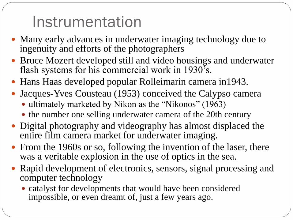
Instrumentation Many early advances in underwater imaging technology due to
ingenuity and efforts of the photographers
Bruce Mozert developed still and video housings and underwater flash systems for his commercial work in 1930’s.
Hans Haas developed popular Rolleimarin camera in1943.
Jacques-Yves Cousteau (1953) conceived the Calypso camera ultimately marketed by Nikon as the “Nikonos” (1963)
the number one selling underwater camera of the 20th century
Digital photography and videography has almost displaced the entire film camera market for underwater imaging.
From the 1960s or so, following the invention of the laser, there was a veritable explosion in the use of optics in the sea.
Rapid development of electronics, sensors, signal processing and computer technology catalyst for developments that would have been considered
impossible, or even dreamt of, just a few years ago.

Like in the consumer photography market, digital photography and videography has almost displaced the entire film camera market for underwater imaging.
From the 1960s or so, following the invention of the laser, there was a veritable explosion in the use of optics in the sea.
The rapid development of electronics, sensing technology and signal processing and computer technology have acted as a catalyst for developments that would have been considered impossible, or even dreamt of, just a few years ago.
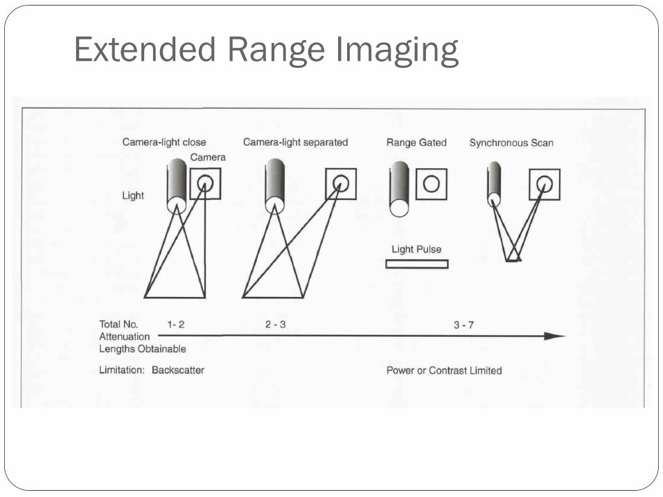
Extended Range Imaging

Conventional 2D optical imaging
The traditional form of subsea imaging is based around 2D still
cameras.
As is well known, an inverted “real” image of a scene is formed
on the optical sensor.
Depending on lens parameters (aperture, focal length, quality)
and lens-subject distance the image so formed replicates the
intensity distribution of the scene;
but only a plane which coincides with the film is sharply in focus
The use of artificial sources such as flash and stroboscopic
lighting established photography as a vital tool for the subsea
science.

Conventional 2D optical imaging - 2 From the 1960s onwards new light sources like the laser or high-power
LEDs brought a new dimension into underwater imaging.
Traditionally the optical sensor in 2D photography was photographic silver
halide film, but this has now been almost exclusively superseded by CCDs
or CMOS arrays.
Movie cameras and later electronic video cameras brought in the time
dimension
Live, real-time, video cameras also are used for steering and manipulating ROVs and
AUVs.
High-Definition (HD) video with image capture at up to 30 Hz
progressive or 60 Hz interlaced scan and a 1980 by 1080 pixel resolution.
3D Imaging
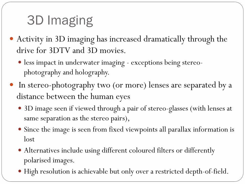
Activity in 3D imaging has increased dramatically through the
drive for 3DTV and 3D movies.
less impact in underwater imaging - exceptions being stereo-
photography and holography.
In stereo-photography two (or more) lenses are separated by a
distance between the human eyes
3D image seen if viewed through a pair of stereo-glasses (with lenses at
same separation as the stereo pairs),
Since the image is seen from fixed viewpoints all parallax information is
lost
Alternatives include using different coloured filters or differently
polarised images.
High resolution is achievable but only over a restricted depth-of-field.

Other 3D Photogrammetric systems use two or more cameras to extract
dimensional information
If quantitatively calibrated with a reference dimension, allows measurement of 3D
locations and size.
Measurement accuracy is limited, particularly along the camera axes.
Technology mature, but data analysis is complex. Surface texture used to register
images between cameras
3DTV systems receiving considerable attention in entertainment industry
Commercial implementation is based on stereo-photography (with glasses - anaglyph,
polarised, shuttered).
Auto-stereo systems (no glasses) are prone to eye strain and physiological effects.
Although in early development - attracts considerable investment - developments to
proceed dramatically.
Application is initially likely to be for real-time imaging and steering of ROVs

Holography Holography has begun to make a considerable impact in marine biology:
accelerated by the introduction of digital recording rather than on film.
Offers marine biologists an alternative to conventional 3D recording of living, motile organisms and particles in their natural environment
Several subsea holographic cameras, both classical and digital, have been used successfully
The earliest holocameras recorded the holographic interference pattern on extremely-fine grain silver halide emulsions. They were all big, bulky and not easy to deploy underwater
One such system, HoloMar uniquely combined simultaneous recording of in-line (ILH) and off-axis holograms (OAH) of overlapping volumes of the water column.
Deployed in Loch Etive, Scotland, enumeration and identification of specific planktonic organisms together with their size, orientation and three-dimensional spatial distribution was achieved.
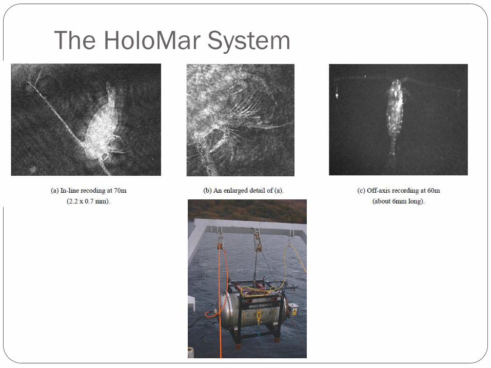
The HoloMar System

Digital Holography
Since the mid-1990s advances in computational power and electronic
detectors brought digital holographic recording to the fore.
Digital holographic cameras are smaller and faster than their classical
counterpart and have almost exclusively superseded them.
Subsea DH though uses primarily the ILH geometry and little progress has
been made in incorporating off-axis schemes underwater.
Although providing the highest resolution (to a few micrometres dimension),
ILH is limited by the concentrations of particles that can be recorded and the
maximum size of object that can be imaged.
Holography has come into its own for imaging of plankton and sediment
transport but has yet to make an impact in other areas.
Difficulties are data extraction and management

eHoloCam System

10,000 m – An attempt
Our goal from Summer 2010
To deploy eHoloCam to 10 000 m depth!!
KermadecTrench – 4 days NE of NZ
One of deepest points on the planet
eHoloCam redesigned into 3 housings
Laser & optics
On-board computer
CMOS camera housing
Housing designed for 1000 x atmospheric pressure
Pressure tested to 7000 m effective depth
eHoloCam shipped to NZ in Feb 2012

Extended Range Imaging
As indicated earlier, one of the biggest problems in underwater
imaging is the ever-present effect of backscattered light.
Apart from physically separating the source and detector, many
systems have been devised to try and minimise this problem.
They can be sub-divided into various groupings such as
spatial discrimination (Laser Line Scan)
time discrimination (Range Gating)
structured lighting systems
scattered light rejection by modulation/modulation,
polarisation discrimination
multiple-perspective image construction

Synchronous Scan (Laser Line Scanners)
PMT
Target
Rotating CamMirrors
Detector
FOV
Target
Radiance
Backscattered
Laser Light
Laser
Direction of Sensor Motion
Strengths
• Range: 4-5 attenuation lengths
• High signal to noise
• Spectral & polarimetric configurable
Weaknesses
• Small depth of field
• Movable parts prone to failure
Laser Line Scan Imaging
Very finely detailed images (millimetre to centimetre scale) of the seafloor can be obtained in shallow coastal waters even in relatively high turbidity and the presence of high levels of backscatter.
The use of LLS represented a significant improvement over traditional side-scan sonar for use in benthic imaging.
LSS also used in imaging of sediments and biological communities marine flora and fauna and submerged structures such as pipelines.
More recently, military specification three-colour LLS technology has been used to image fluorescence signatures from corals to determine the quantitative distribution and abundance of various functional groups on coral reefs.
Variations on the LLS principle include techniques for 3D imaging or pulsed lasers for better discrimination

LLS Images (Raytheon)
A contrast image and a range image from the Raytheon LLS
system. The two images can be combined to produce the
perspective image on the right.

Range-gating Systems
A short pulse of laser light creates a “slice” of illumination.
An associated camera is opened just as the pulse of light arrives at the
detector after its round trip to the object and back.
The backscattered light arrives before the shutter is opened and is thus
eliminated.
High speed gated and intensified imaging detectors are needed e.g. pulsed
frequency-doubled Nd-YAGs at up to 100 Hz prf.
One of the more promising attempts is the Laser Underwater Camera
Imaging Enhancer (LUCIE & LUCIE2) system (Fournier et al 1993).
2 kHz high repetition rate laser and averages over the sequence of images.
Deployed from ROV and imaged propeller blades over five ALs.
A variation on the theme is use a hybrid of scanning with a fan-beam and
time-resolved gating known as Streak Tube Imaging LIDAR (STIL).

Range Gated Systems(Streak Tube Imaging Lidar, Arête
Strengths
• Range: 4-5 attenuation lengths
• Range image combined with reflectance
• Spectral & polarimetric configurable
Weaknesses
• 4-5 attenuation length range (same as
LLS)
• Fan beam reduces photon density
Returning
Pulse
Photocathode
Electronic
Gate
t
v
t
v
Detector
Array
Electron
Stream
Sweep
Plates

Structured Light With structured lighting (also known as pattern or fringe projection)
a known pattern or sheet of light is projected onto, or scanned
across, a scene;
Pattern can be a 1D stripe or a 2D grid of spots or a series of
regularly spaced parallel lines
The surface deforms the profile of the pattern which then reveals the
structure of the surface
For a single stripe a well-defined line is swept across FOV to gather
distance info one strip at a time.

Video plankton recorders and variants
A technique which is well-known for plankton studies is the Video
Plankton Recorder, (developed at WHOI) and its variants.
It is essentially a 2D imaging system but utilising transmitted rather
than reflected light and operates as a towed underwater optical
microscope.
A beam of light is passed through the scene of interest, which must
be relatively transparent, and an image is formed.
A video camera pointing towards the light source focuses on a
specific plane of the image.
By using stroboscopic illumination up to 60 images per second can
be obtained at high resolution in the size range 0.1 mm to 1 cm;
identification to species level not possible.

VPR

Optical Plankton Counter The Optical Plankton Counter (OPC) and its later variant, the Laser
Optical Plankton Counter (LOPC) are not strictly imaging systems; they are more correctly categorised at sensing systems.
Like the VPR a beam of light passes through the target volume to an electronic detector array. The OPC measures and transmits the cross-sectional area of each particle passing through the beam, but there are inherent limitations with its measurement capabilities.
The most dominant is that of the coincidence limit, that is, the density at which there is a significant probability of two or more particles occurring in the beam simultaneously.
As a result, multiple particles are counted as one count and the size is presented as the sum of cross-sectional areas of all particles in the beam.
In the case of the OPC, coincidence became a problem at plankton density of around 10,000 m−3. The area and shape occluded by the particle is measured relative to the dimensions of the diode array detector. Sizes in range 250 m to 25 mm can be counted.

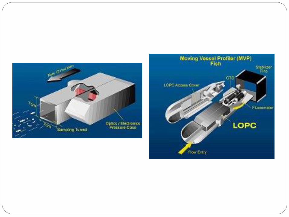
Laser Optical Particle Counter (LOPC)
The LOPC was designed to resolve these limitations and to provide
further zooplankton identification capabilities by measuring the shape
profiles of plankton larger than 1.5 mm.
In the LOPC, a laser diode coupled with a cylindrical lens produces a
sheet of 1 mm x 35 mm dimensions; the path length of the system is
doubled by folding with a prism and sending back through the water: the
total frontal area occupied by the beam in a standard sampling tunnel is 70
× 70 mm and recording takes place on a 35 element diode array.
The occlusion problem does not occur until concentrations of 106/m3 at
100 m resolution.
The LOPC: splits size measurement into two ranges: single element
detection over 100 to 1500 m and shape profile over 1500 – 35 000 m.

Summary
Short overview of underwater imaging and optics
Developments in lasers, LEDs, electronic sensors and
computer processing all combine to ensure that use of optics
will dominate
Problems remain however with propagation of light through
water
With some techniques data extraction and interpretation
remains an issue
AND NOW……