Embed Size (px)
Citation preview
IMI CONFERENCE 2013
Subsidence Modeling
Joshua Clay, P.E. &
Butch Wilford W. Cheatham, P.E., S.I.T.
HDR Engineering Inc. Murphysboro, Illinois

IMI CONFERENCE 2013
Illinois Basin Coal Mining
• Illinois Basin Coal ‒ IL, IN, and west KY
‒ Bituminous
‒ 10,000 – 12,500 btu/lb
‒ Mostly >2% sulfur
• 2010 Statistics ‒ 76 Active Mines
• 34 Underground
• 42 Surface
‒ 105,089,000 Tons Produced
‒ 9.69% of U.S. Production
‒ 14.4 Billion Tons of Reserve

IMI CONFERENCE 2013
Underground Coal Mining
• Used when coal is deep and can’t economically or physically be
reached by removal of overburden
• Removal of coal underground causes sinking or “subsidence” of
the ground surface
• Removed by Longwall mining or Room and Pillar mining
methods

IMI CONFERENCE 2013
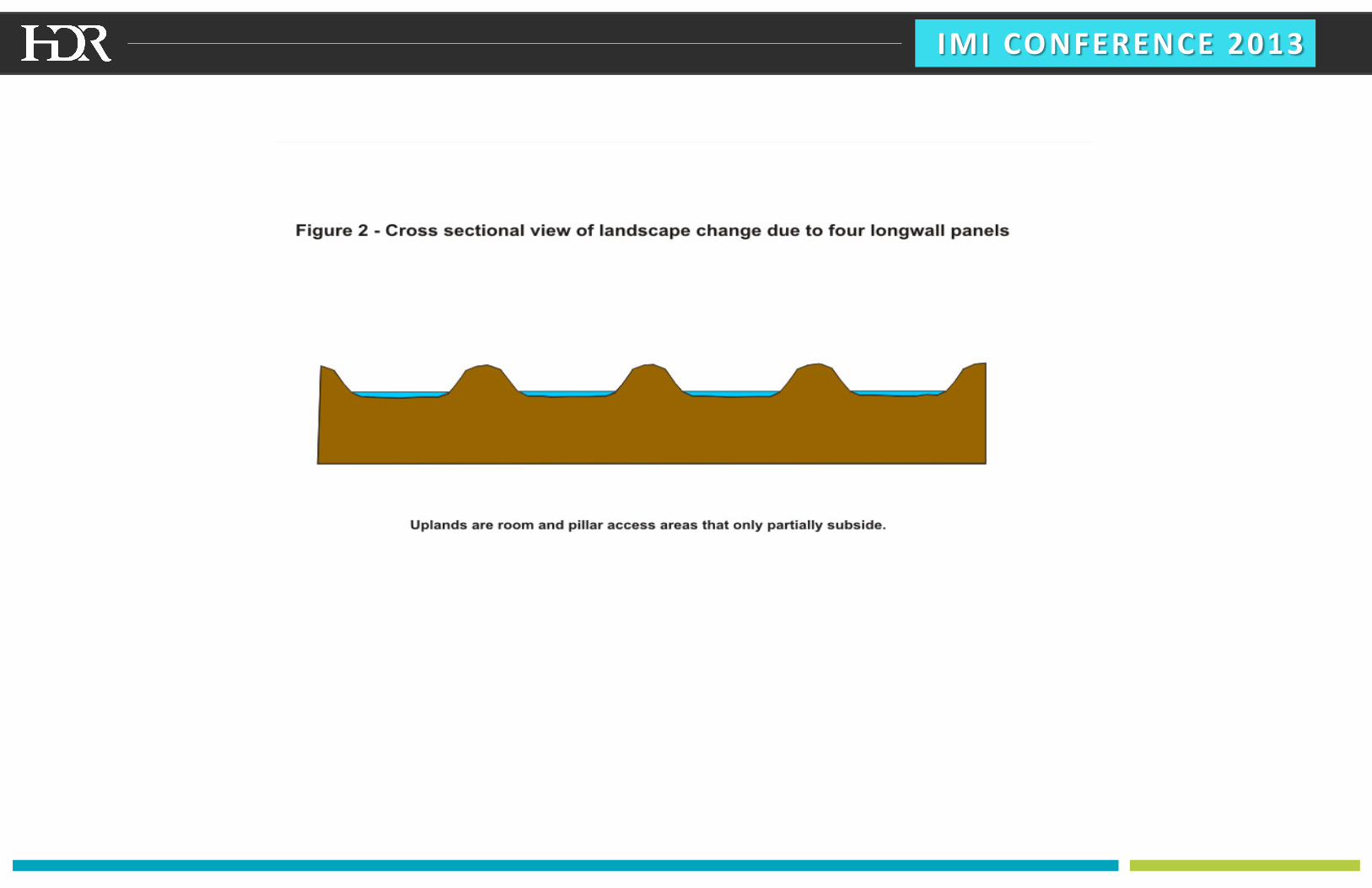
Longwall vs. Room and Pillar Mining
• In room-and-pillar mining, “rooms” are excavated, and pillars of
coal are left in place between the rooms to support the mine
roof.
• Longwall mining involves almost complete extraction of the
coal contained in a large rectangular block or “panel” of coal,
and the roof in the mined-out area is allowed to collapse. Long
“chain pillars” of coal are left between the mined out panels.

IMI CONFERENCE 2013
Longwall vs. Room and Pillar Mining
• Artist rendering indicating the two
methods of mining

IMI CONFERENCE 2013

IMI CONFERENCE 2013
Longwall Mining
• Began in 17th Century England
• Technology advances in 1950s led to use in US
• In past few decades it has increased due to changes in longwall
panel dimensions and improvements in longwall equipment.
• Longwall panels in Illinois are typically ‒ 330 – 970 ft below surface
‒ 900 – 1,800 ft wide
‒ Up to 4 miles long

IMI CONFERENCE 2013
Benefits of Longwall Mining
• Longwall results in extraction of 90% of the coal resource vs. 50%
extracted by room and pillar mining.
• Coal left by room and pillar is “lost” and can never be mined in
the future
• Improved safety
• Mines are easier to manage
• Involves no blasting
• Recovers more coal from deeper beds
• The coal haulage system is simpler
• Ventilation is better controlled
• Subsidence of the surface is more predictable.

IMI CONFERENCE 2013
Subsidence
• Subsidence ‒ Immediate and predictable
‒ Somewhat uniform
‒ Surface max subsidence ~70-80% of seam
thickness
‒ Typical Illinois subsidence is up to 6 feet in
the center of panels
‒ 98% + subsidence completed within a year
(source: Illinois State Geological Survey, Circular 573)

IMI CONFERENCE 2013
IMI CONFERENCE 2013

IMI CONFERENCE 2013
Why Predict Subsidence
• Subsidence can cause: ‒ Ponding
‒ Decrease in crop productivity (from flooding)
‒ Damage to houses, barns, communication towers
‒ Damage to or flooding of roads and railroads
‒ Damage to utility lines (above and underground)
• Mining companies routinely correct the effects of subsidence to
prevent the above from happening.
• Owners of surface properties above longwall mines are assured
the surface will be restored to pre-mining capability by
regulation.

IMI CONFERENCE 2013
Impacts to Structures
The coal company took measures to protect this home in advance of subsidence.
Structures were raised from the foundations and kept level during subsidence.
Foundations were restored and structures lowered onto them after damaging ground
movements ceased. Foundations are often replaced during year or two after mining.
(source: Illinois State Geological Survey, Circular 573)

IMI CONFERENCE 2013
Impacts to Roads
(source: Illinois State Geological Survey, Circular 573)

IMI CONFERENCE 2013
Predicting Subsidence
Surface Deformation Prediction System
• Originally developed in 1987 at Virginia
Tech. by Dr. Michael Karmis and Dr.
Zach Agioutantis.
• Program has been refined to the Version
6.0 used today.
• SDPS uses two alternative methods for
calculating subsidence:
• Profile Function Method
• Influence Function Method

IMI CONFERENCE 2013
Background on the Influence Function Method
• Calculates magnitude of predicted
subsidence based on the complex equation
to the right.
• Factors influencing subsidence behavior
include, but are not limited to;
• Overburden depth
• Makeup of overlying geologic strata
• Coal seam thickness
• Longwall panel geometry (width,
length, etc.)

IMI CONFERENCE 2013
SDPS Imports a Mine Plan with AutoCAD
• The geologic boring data is
used in conjunction with
AutoCad to develop a surface
model for the top of coal seam.
• The average % hardrock and
coal seam thickness is also
determined and entered into
this section to aid in the
subsidence modeling.

IMI CONFERENCE 2013
SDPS Imports Ground Surface Topography Points
as Text • To get the best predictions,
we take the points and
breaklines used to generate
the flown topographic
contours and turn them all
into points using Bentley’s
Geopak program. This
program will assign point
codes to enable the lines to
be reassembled after the
points are subsided with
SDPS.

IMI CONFERENCE 2013
SDPS Calculates Subsidence and Creates Text Files
• SDPS will generate several text
files based on the selections
made.
• We use these files to generate
predicted ground surface
contours and ponding in
Microstation/Geopak or
AutoCAD/Civil 3D.

IMI CONFERENCE 2013
Typical Post Subsidence Map
• Prepared as a requirement of OMM mine permit application.
• Map Illustrates important features related to the subsidence caused by the mining.
o Isopachs
o Limit of predicted subsidence
o Ponding depressions or other areas that may require corrective measures to drain
properly after mining has occurred.
o Angle of draw

IMI CONFERENCE 2013
Typical Stream Subsidence Map
• Indicates the effects that the subsidence may have on established waterways and insures that
these effects can be mitigated before mining actually takes place.
• This map coupled with the stream profiles offers a conceptual estimate of the work involved to
maintain positive drainage.

IMI CONFERENCE 2013
Typical Stream Profiles
• Compares the existing waterway profile to the post mining waterway profile and
indicates areas that need correction as well as the extent of the work involved.
• Stream profiles typically need adjustment at the chain pillars and any other areas
where subsidence is minimal or does not occur.

IMI CONFERENCE 2013
Questions?


![Land Subsidence Modelling Using Particle Swarm Optimization … · [9] Detection of land subsidence in Semarang ... [10] Modeling alluvial aquifer using ... December 08, 2019](https://img.pdfslide.net/doc/110x75/610848f4e09ef8046839856a/land-subsidence-modelling-using-particle-swarm-optimization-9-detection-of-land.jpg)
![Study of land subsidence around the city of Shirazscientiairanica.sharif.edu/article_2167_b3bb54f3fcf13e2c...tectonic subsidence, and etc. [2]. Land subsidence, as a serious crisis,](https://img.pdfslide.net/doc/110x75/5f81603bf7f7323e190f6f7c/study-of-land-subsidence-around-the-city-of-s-tectonic-subsidence-and-etc.jpg)