Embed Size (px)
Citation preview
Substation Secondary Asset Health Monitoring and Management System
DOE Grant Award #DE-OE0000850
Kevin Chen & Lin ZhangElectric Power Group
[email protected], [email protected]
June 13, 2017Washington, DC
DOE/OE Transmission Reliability Program
Outline
Introduction
Background
Objective
Technical Merit
Technical Approach
Project Schedule
Current Status
Q&A
2
Introduction
DOE/OE and DOE/NETL– Phil Overholt, Program Manager and Alicia Dalton-Tingler, Project Officer
American Electric Power (AEP) – Sub-recipient – Project Manager / Alternate – Carlos Casablanca / Yanfeng Gong
Professor Anjan Bose (Washington State University) – Technical Advisor
Electric Power Group, LLC – Principal Investigators – Kevin Chen, Lin Zhang
– Key Project Personnel – Ken Martin, Simon Mo, Tingyang Zhang, Neeraj Nayak, Joshua Chynoweth
© Electric Power Group 2017. All rights reserved3
Billions of dollars on transmission and distribution assets Key substation assets include transformers, circuit breakers,
instrument transformers (CTs, PTs, CCVTs) and IntelligentElectronic Device (Relays, PMU, DFRs)
Synchrophasor measurement systems have been widelyinstalled in the North American power grids over the lastdecade
Data from such assets can be used for asset health monitoringand take proactive steps to prevent equipment failure
Proper functioning of substation assets is critical for powersystem operations, reliability and personnel safety
Background
© Electric Power Group 2017. All rights reserved4
Research, design, develop and demonstrate software application in substation(s) to:– Collect three phase measurements from substation equipment– Process data from PMUs, DFRs and Instrument Transformers to derive
synchrophasor equivalents and run a three phase Substation Linear State Estimator (SLSE) in real-time
– Monitor and characterize equipment data signatures– Detect signature anomalies– Alert end-users and provide equipment signatures for detailed forensic
analysis– Enable end-users to take needed proactive actions – calibration,
repairs, replacement
Objective
© Electric Power Group 2017. All rights reserved5
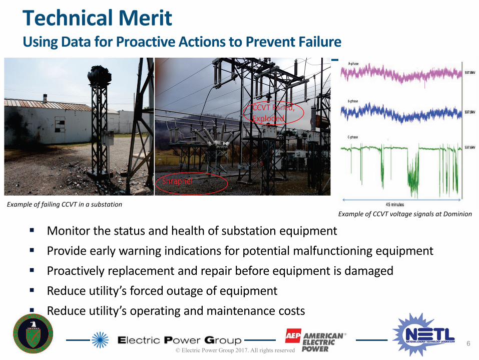
Monitor the status and health of substation equipment Provide early warning indications for potential malfunctioning equipment Proactively replacement and repair before equipment is damaged Reduce utility’s forced outage of equipment Reduce utility’s operating and maintenance costs
Technical Merit Using Data for Proactive Actions to Prevent Failure
Example of failing CCVT in a substationExample of CCVT voltage signals at Dominion
© Electric Power Group 2017. All rights reserved6
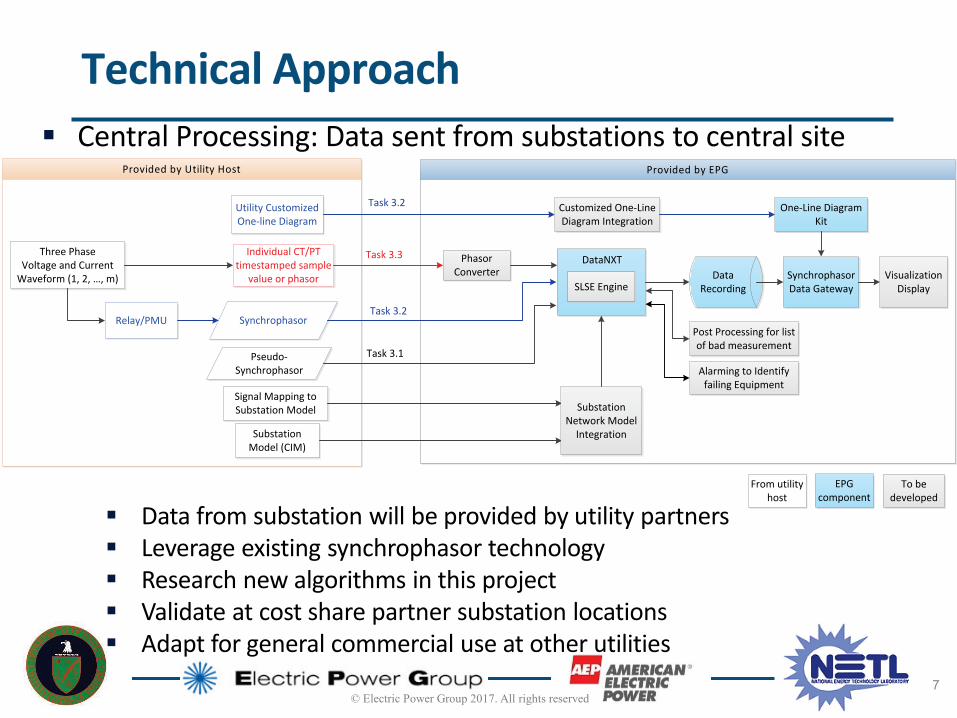
Data from substation will be provided by utility partners Leverage existing synchrophasor technology Research new algorithms in this project Validate at cost share partner substation locations Adapt for general commercial use at other utilities
Technical Approach Central Processing: Data sent from substations to central site
© Electric Power Group 2017. All rights reserved7
Provided by Utility Host Provided by EPG
Individual CT/PT timestamped sample
value or phasor
Three PhaseVoltage and Current
Waveform (1, 2, …, m)
Task 3.3
Relay/PMUPost Processing for list of bad measurement
Substation Model (CIM)
Data Recording
SynchrophasorTask 3.2
Pseudo-Synchrophasor
Task 3.1Alarming to Identify
failing Equipment
Visualization DisplaySLSE Engine
DataNXT
Utility Customized One-line Diagram
Task 3.2
Signal Mapping to Substation Model Substation
Network Model Integration
Synchrophasor Data Gateway
One-Line Diagram Kit
EPG component
To be developed
From utility host
Customized One-Line Diagram Integration
Phasor Converter
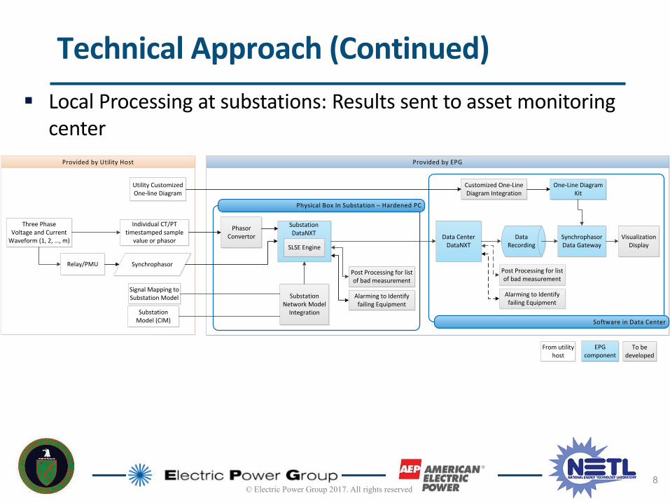
Technical Approach (Continued) Local Processing at substations: Results sent to asset monitoring
center
© Electric Power Group 2017. All rights reserved8
Provided by Utility Host Provided by EPG
Physical Box In Substation – Hardened PC
Software in Data Center
Individual CT/PT timestamped sample
value or phasor
Three PhaseVoltage and Current
Waveform (1, 2, …, m)
Phasor Convertor
Relay/PMU
Substation Model (CIM)
Data Recording
Synchrophasor
Visualization DisplaySLSE Engine
Substation DataNXT
Utility Customized One-line Diagram
Signal Mapping to Substation Model Substation
Network Model Integration
Synchrophasor Data Gateway
One-Line Diagram Kit
EPG component
To be developed
From utility host
Customized One-Line Diagram Integration
Data Center DataNXT
Post Processing for list of bad measurement
Alarming to Identify failing Equipment
Post Processing for list of bad measurement
Alarming to Identify failing Equipment
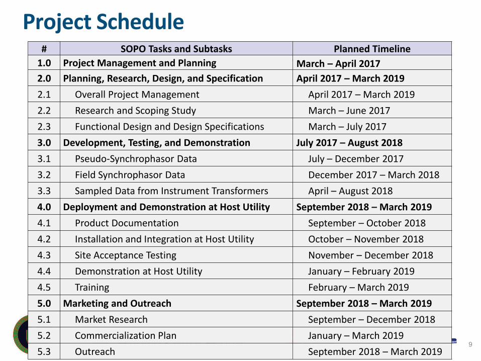
Project Schedule # SOPO Tasks and Subtasks Planned Timeline
1.0 Project Management and Planning March – April 20172.0 Planning, Research, Design, and Specification April 2017 – March 20192.1 Overall Project Management April 2017 – March 20192.2 Research and Scoping Study March – June 20172.3 Functional Design and Design Specifications March – July 20173.0 Development, Testing, and Demonstration July 2017 – August 20183.1 Pseudo-Synchrophasor Data July – December 20173.2 Field Synchrophasor Data December 2017 – March 20183.3 Sampled Data from Instrument Transformers April – August 20184.0 Deployment and Demonstration at Host Utility September 2018 – March 20194.1 Product Documentation September – October 20184.2 Installation and Integration at Host Utility October – November 20184.3 Site Acceptance Testing November – December 20184.4 Demonstration at Host Utility January – February 20194.5 Training February – March 20195.0 Marketing and Outreach September 2018 – March 20195.1 Market Research September – December 2018 5.2 Commercialization Plan January – March 20195.3 Outreach September 2018 – March 2019
9

Task 2.2 Research and Scoping Study - Equipment
© Electric Power Group 2017. All rights reserved10
Current Transformer (CT)
Potential Transformer (PT)
Coupling Capacitor Voltage Transformer (CCVT)
Source: IEC Capacitive & Coupling Capacitor Voltage Transformers (CVT & CCVT), http://www.gegridsolutions.comSource: Instrument Transformers – Technical Information
& Application Guide, http://www.abb.com
Conducting a research and scoping study of bad data pattern and relationship to types of equipment failure, as well as alarming criterial for failure detection
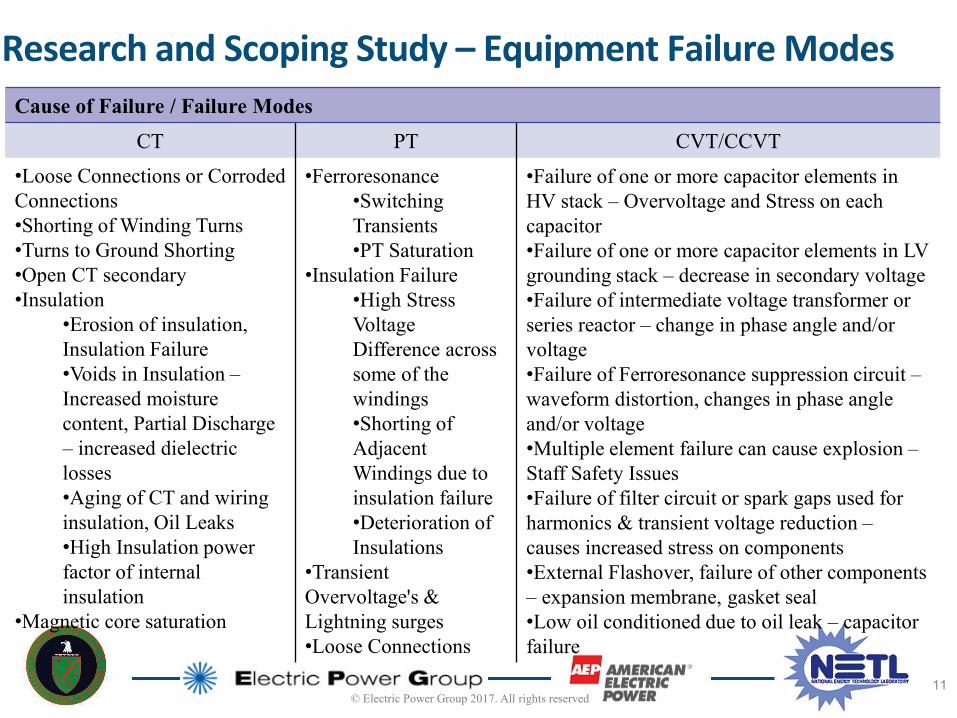
Research and Scoping Study – Equipment Failure Modes
© Electric Power Group 2017. All rights reserved11
Cause of Failure / Failure ModesCT PT CVT/CCVT
•Loose Connections or Corroded Connections•Shorting of Winding Turns•Turns to Ground Shorting•Open CT secondary•Insulation
•Erosion of insulation, Insulation Failure•Voids in Insulation –Increased moisture content, Partial Discharge – increased dielectric losses•Aging of CT and wiring insulation, Oil Leaks•High Insulation power factor of internal insulation
•Magnetic core saturation
•Ferroresonance•Switching Transients•PT Saturation
•Insulation Failure•High Stress Voltage Difference across some of the windings•Shorting of Adjacent Windings due to insulation failure•Deterioration of Insulations
•Transient Overvoltage's & Lightning surges•Loose Connections
•Failure of one or more capacitor elements in HV stack – Overvoltage and Stress on each capacitor•Failure of one or more capacitor elements in LV grounding stack – decrease in secondary voltage•Failure of intermediate voltage transformer or series reactor – change in phase angle and/or voltage•Failure of Ferroresonance suppression circuit –waveform distortion, changes in phase angle and/or voltage•Multiple element failure can cause explosion –Staff Safety Issues•Failure of filter circuit or spark gaps used for harmonics & transient voltage reduction –causes increased stress on components•External Flashover, failure of other components – expansion membrane, gasket seal•Low oil conditioned due to oil leak – capacitor failure
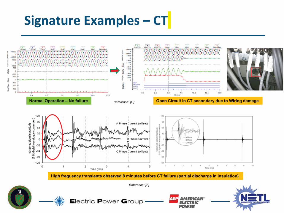
Signature Examples – CT
Open Circuit in CT secondary due to Wiring damage
High frequency transients observed 8 minutes before CT failure (partial discharge in insulation)
Normal Operation – No failure Reference: [G]
Reference: [F]
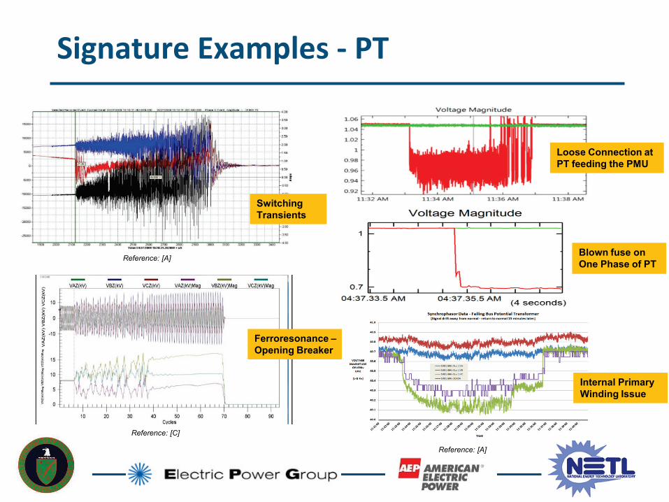
Signature Examples - PT
Ferroresonance –Opening Breaker
Switching Transients
Loose Connection at PT feeding the PMU
Blown fuse on One Phase of PT
Internal Primary Winding Issue
Reference: [A]
Reference: [A]
Reference: [C]
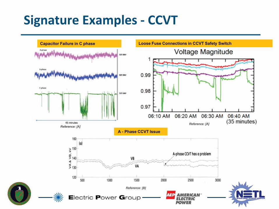
Signature Examples - CCVTLoose Fuse Connections in CCVT Safety SwitchCapacitor Failure in C phase
A - Phase CCVT IssueReference: [A]
Reference: [A]
Reference: [B]

Available Inputs and Desired Output
• Raw PMU Data
• LSE Data
• Redundant PMUs
• Other Phases
• DFR Data*
Available Input - Data
• Minimal false positive
• Minimal false negative
• Maximize prediction time
• Within Computing
Constraints
Desired Output – Flag Asset Fail
© Electric Power Group 2017. All rights reserved15
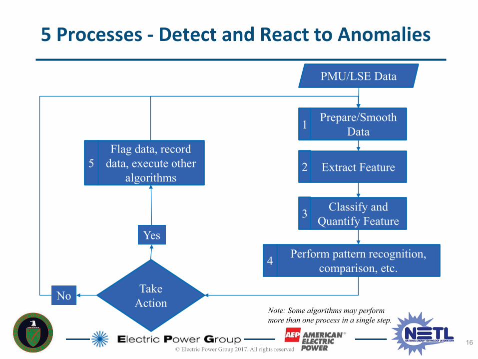
Prepare/Smooth Data
Extract Feature
Classify and Quantify Feature
Perform pattern recognition, comparison, etc.
Flag data, record data, execute other
algorithms
Take Action
PMU/LSE Data
No
Yes
1
2
3
4
5
5 Processes - Detect and React to Anomalies
Note: Some algorithms may perform more than one process in a single step.
© Electric Power Group 2017. All rights reserved16

Current Project Status
Contract Awarded: March 15th, 2017 Project Planning Meeting with AEP: March 29 DOE Official Kickoff Meeting: April 10 PMP Update Completion: April 14 Project Update to Industry
– NERC SMS: May 18
Task 2.2 Research and Scoping Study completion: June 9 Task 2.3 Functional Design and Design Specifications: Started
© Electric Power Group 2017. All rights reserved17

Q & A
18
Electric Power Group (EPG)201 S. Lake Ave. Suite 400
Pasadena, CA 91101
(626) 685 2015
Heng (Kevin) Chen [email protected]
Thank You!
BACKUP SLIDES

Utilize Substation Linear State Estimator (SLSE) technology tosolve the substation states and detects bad measurementsfrom PMUs, DFR’s and other measuring devices
SLSE results will be saved in a local archiver for post processing
Develop algorithms and logic to detect measurementanomalies and identify problem root causes
Develop alarming module to trigger early warning and alarminformation for failing equipment, to the responsible operatorsand engineers or transmission field service technician
Technical Approach
© Electric Power Group 2017. All rights reserved20
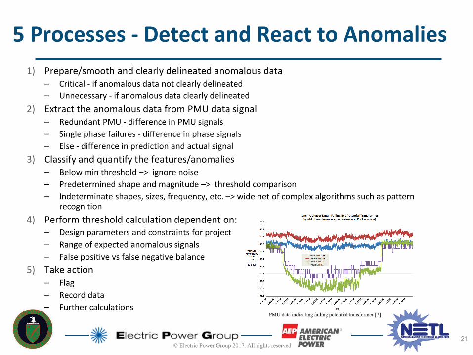
1) Prepare/smooth and clearly delineated anomalous data– Critical - if anomalous data not clearly delineated– Unnecessary - if anomalous data clearly delineated
2) Extract the anomalous data from PMU data signal– Redundant PMU - difference in PMU signals– Single phase failures - difference in phase signals– Else - difference in prediction and actual signal
3) Classify and quantify the features/anomalies– Below min threshold –> ignore noise– Predetermined shape and magnitude –> threshold comparison– Indeterminate shapes, sizes, frequency, etc. –> wide net of complex algorithms such as pattern
recognition4) Perform threshold calculation dependent on:
– Design parameters and constraints for project– Range of expected anomalous signals– False positive vs false negative balance
5) Take action– Flag– Record data– Further calculations
5 Processes - Detect and React to Anomalies
PMU data indicating failing potential transformer [7]
21© Electric Power Group 2017. All rights reserved
General approach to direct feature extraction without conditioning
– Peak (max), derivative, difference, normalization, detrend, frequency filters, signal to noise ratio
Simple processing/smoothing (moving window)– Averaging smoothing methods (moving average, moving RMSE, weighted moving
average)– Exponential Smoothing Methods
Dimension/Data reduction – Time or Frequency analysis
• Singular value decomposition (SVD)/Principal component analysis (PCA) [5]• Discrete/Fast Fourier Transform (DFT)/(FFT)
– Already performed on PMU data– Time-frequency analysis algorithm
• Matching Pursuit Decomposition (MPD) [3][4]• Wavelet transform (WT) [11]
Data conditioning and removing bad data– Quadratic prediction model and Kalman filter [9]
Algorithm for Feature Extraction
Note: Algorithms may be used in series, parallel or combination.
22© Electric Power Group 2017. All rights reserved
A. NASPI Technical Report, “Diagnosing Equipment Health and Mis-operations with PMU data”, May 2015
B. Bogdan Kasztenny and Ian Stevens, “Monitoring Ageing CCVTs – Practical Solutions with Modern Relays to Avoid Catastrophic Failures”, March 2007
C. David Shipp and Thomas Dionise, IEEE Tutorial, “ Switching Transients, Transformer Failures, Practical Solutions”, Feb 2016
D. L. Sevov, J. Cardenas and Y. Sun, "CT Failure Detection For Differential Protection Applications," 2008 61st Annual Conference for Protective Relay Engineers, College Station, TX, 2008, pp. 498-511. doi:10.1109/CPRE.2008.4515076
E. Deepak Rampersad, “Investigation into current transformer failures within Eskom distribution”, December 2010
F. Darren Spoor and Jian Guo Zhu, Monitoring current transformer secondary circuits to forewarn of catastrophic insulation faults
G. D. Costello, "Open-circuited CT misoperation and investigation," 2014 67th Annual Conference for Protective Relay Engineers, College Station, TX, 2014, pp. 383-392,doi: 10.1109/CPRE.2014.6799015
References
References[1] Transmission & Distribution Committee - IEEE Power & Energy Society, “Electric Signatures of Power Equipment Failures,” 2015.[2] M. Al Karim, M. Chenine, K. Zhu, and L. Nordstrom, “Synchrophasor-based data mining for power system fault analysis,” IEEE
PES Innov. Smart Grid Technol. Conf. Eur., pp. 1–8, 2012.[3] H. Jiang, X. Dai, D. W. Gao, J. J. Zhang, Y. Zhang, and E. Muljadi, “Spatial-Temporal Synchrophasor Data Characterization and
Analytics in Smart Grid Fault Detection, Identification, and Impact Causal Analysis,” IEEE Trans. Smart Grid, vol. 7, no. 5, pp. 2525–2536, 2016.
[4] H. Jiang, J. J. Zhang, W. Gao, and Z. Wu, “Fault detection, identification, and location in smart grid based on data-driven computational methods,” IEEE Trans. Smart Grid, vol. 5, no. 6, pp. 2947–2956, 2014.
[5] J. M. Lim and C. L. Demarco, “Model-free voltage stability assessments via singular value analysis of PMU data,” Proc. IREP Symp. Bulk Power Syst. Dyn. Control - IX Optim. Secur. Control Emerg. Power Grid, IREP 2013, 2013.
[6] R. Meier et al., “Power system data management and analysis using synchrophasor data,” 2014 IEEE Conf. Technol. Sustain., pp. 225–231, 2014.
[7] A. Silverstein, “Diagnosing Equipment Health and Mis-operations with PMU Data,” 2015.[8] Xiaodong Liang and S. A. Wallace, “Processing synchrophasor data using a feature selection procedure,” in 2016 IEEE PES
Asia-Pacific Power and Energy Engineering Conference (APPEEC), 2016, pp. 273–277.[9] K. D. Jones, A. Pal, and J. S. Thorp, “Methodology for Performing Synchrophasor Data Conditioning and Validation,” IEEE
Trans. Power Syst., vol. 30, no. 3, pp. 1121–1130, 2015.[10] N. Dahal, R. L. King, and V. Madani, “Online dimension reduction of synchrophasor data,” Proc. IEEE Power Eng. Soc. Transm.
Distrib. Conf., pp. 1–7, 2012.[11] J. Ning and W. Gao, “Multi-feature extraction for power system disturbances by wavelet transform and fractal analysis,” IEEE
PES Gen. Meet. PES 2010, pp. 1–7, 2010.[12] J. Patel, “Real time big data mining,” The State University of New Jersey, 2016.

Acknowledgment and Disclaimer
• Acknowledgment: "This material is based upon work supported by theDepartment of Energy under Award Number DE-OE0000850.”
• Disclaimer: "This report was prepared as an account of work sponsored by anagency of the United States Government. Neither the United StatesGovernment nor any agency thereof, nor any of their employees, makes anywarranty, express or implied, or assumes any legal liability or responsibilityfor the accuracy, completeness, or usefulness of any information, apparatus,product, or process disclosed, or represents that its use would not infringeprivately owned rights. Reference herein to any specific commercial product,process, or service by trade name, trademark, manufacturer, or otherwisedoes not necessarily constitute or imply its endorsement, recommendation,or favoring by the United States Government or any agency thereof. Theviews and opinions of authors expressed herein do not necessarily state orreflect those of the United States Government or any agency thereof."