Embed Size (px)
Citation preview
WHITE PAPER August 2012
11
Successful AdderLink Infinity ImplementationOptimising your network for AdderLink Infinity
2
Successful Implementation: Optimising your network
Successful AdderLink Infinity ImplementationOptimising your network for AdderLink Infinity
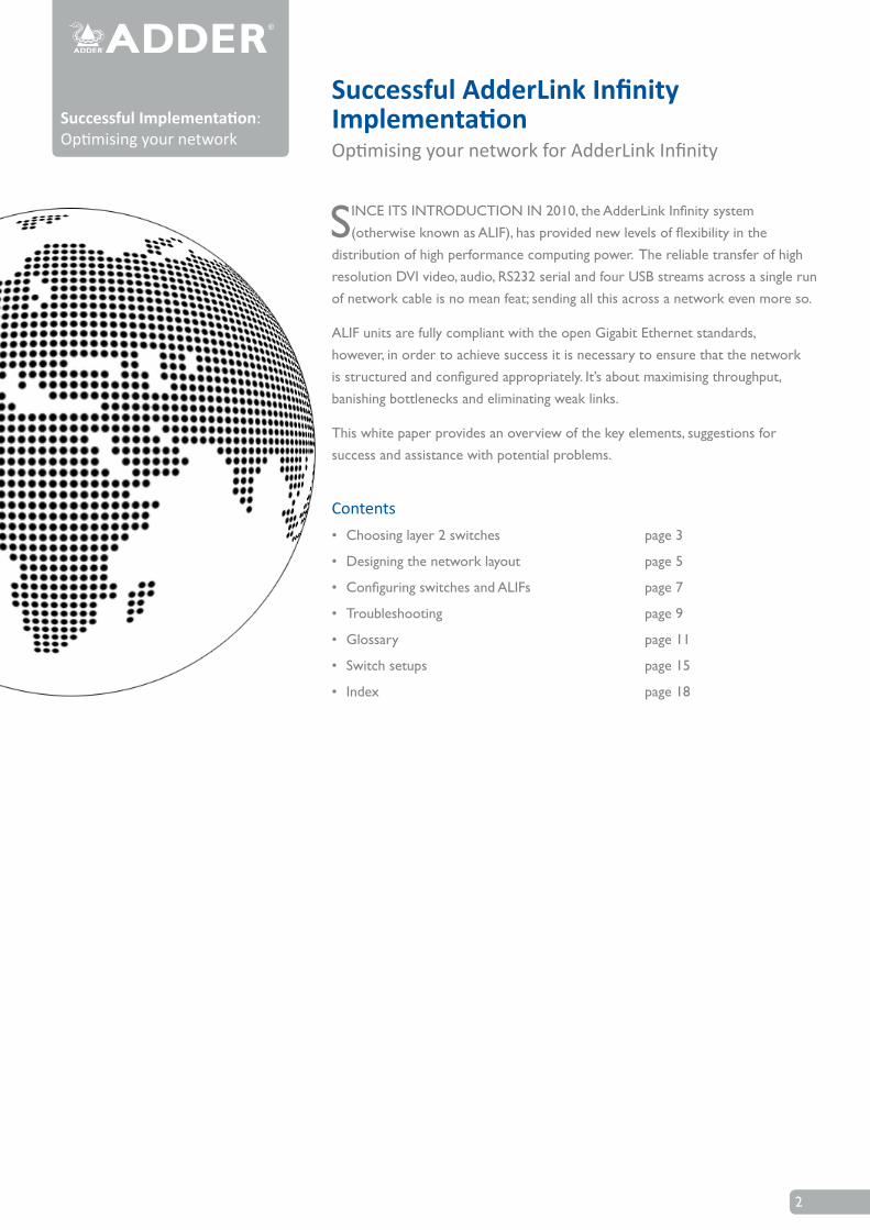
SINCE ITS INTRODUCTION IN 2010, the AdderLink Infinity system (otherwise known as ALIF), has provided new levels of flexibility in the
distribution of high performance computing power. The reliable transfer of high resolution DVI video, audio, RS232 serial and four USB streams across a single run of network cable is no mean feat; sending all this across a network even more so.
ALIF units are fully compliant with the open Gigabit Ethernet standards, however, in order to achieve success it is necessary to ensure that the network is structured and configured appropriately. It’s about maximising throughput, banishing bottlenecks and eliminating weak links.
This white paper provides an overview of the key elements, suggestions for success and assistance with potential problems.
Contents• Choosing layer 2 switches page 3
• Designing the network layout page 5
• Configuring switches and ALIFs page 7
• Troubleshooting page 9
• Glossary page 11
• Switch setups page 15
• Index page 18
3
Choosing layer 2 switchesThis section provides various general and specific recommendations for switches to use with ALIF, however, there is no substitute for testing in real world situations. If you are in doubt about which network switch to choose, the safest approach is to select one from the recommended list of switches on the next page.
General recommendationsThere are certain minimum features that you need to ensure:
• Gigabit (1000Mbps) or faster Ethernet ports,
• Support for IGMP v2 (or v3) snooping,
• Support for Jumbo frames (packets) up to 9216-byte size,
• High bandwidth connections between switches, preferably Fibre Channel.
Additionally:
• Look specifically for switches that perform their most onerous tasks (e.g. IGMP snooping) using multiple dedicated processors - i.e. the tasks are carried out in custom ASIC hardware rather than software routines on a general processor.
• Check the maximum number of concurrent ‘snoopable groups’ each switch can handle and ensure that they meet or exceed the number of ALIF transmitters that will be used to create multicast groups.
• Check the throughput speeds of the switch. Ensure that each port is full duplex (i.e. bi-directional communication) and that the up and down stream data speeds for each port are 1Gigabit per second.
• Wherever possible, use the same switch manufacturer throughout a single subnet and, if possible, the same model of switch - this will simplify configuration and lessen the chances of compatibility issues.
• When choosing Layer 3 switches for the network, at least one must be capable of operating as an IGMP Querier.
IGMP and internal switch designIn recent years, the number of Layer 2 switches that support IGMP snooping has proliferated; however, there is a wide variance in performance between the most effective and the least.
In order to take a peek at (snoop) IGMP messages, Layer 2 switches are required to do something they were not originally designed for: Deciphering every data packet at Layer 3 in order to read the logical addressing and multicast instructions. This requires considerably more processing horsepower than their normal day-job of reading physical MAC addresses at Layer 2.
continued
The trouble with multicastingWhere an ALIF transmitter is required to stream video to two or more receivers, multicasting is the method used.
Multicasting involves the delivery of identical data to multiple receivers simultaneously without the need to maintain individual links. When multicast data packets enter a subnet, the natural reaction of the switches that bind all the hosts together within the subnet, is to spread the multicast data to all of their ports. This is referred to as Multicast flooding and means that the hosts (or at least their network interfaces) are required to process plenty of data that they didn’t request. IGMP offers a partial solution.
IGMP (Internet Group Management Protocol) was developed to help prevent flooding by requiring individual hosts to opt into multicasts. It also provided a mechanism for routers to determine whether any hosts located within their subnet still wished to receive the multicasts. However, this only has an effect at the gateway to the subnet – so if one host requests a multicast, all hosts within the subnet would also receive it.
A solution: IGMP snoopingCue a development in the switches that glue together all the hosts within a subnet: IGMP snooping. IGMP snooping means these layer 2 switches now have the ability to take a peek at the instructions that help routers to do their job. As a result, the switches can then determine exactly which of their own hosts have requested to receive a multicast – and only pass on multicast data to those hosts.

4
Implementing IGMP snooping on a low end switch with a slow processor can cause severe performance problems when data is transmitted at high data rates and/or there are multiple IGMP groups to be monitored. If a switch cannot keep pace, it will cause backlogs where large numbers of data packets are arbitrarily discarded and/or it resorts to sending all multicasts to all ports - causing multicast flooding. Either way, this results in slow video updates and a poor user experience.
A quick note about Layer 3 switches and multicast routing
A key component of subnets used for multicast distribution is the multicast router. This device plays a vital coordinating role in ensuring that network traffic is delivered to the correct Layer 2 switches and the hosts connected to them. Increasingly, the role of router is being fulfilled by Layer 3 switches, particularly for private networks that do not require links to wider external networks. When
selecting a Layer 3 switch for your network, ensure that it can operate as an IGMP Querier and also has sufficient capacity for the size of your subnet.
Specific switches known to work well with AdderLink InfinityThe following models have been tested and found to produce favourable results:
Layer 2 switches
• Cisco 2960
• Cisco 3750
• Cisco 4500
• Cisco 6500
• Extreme Networks X480
• HP Procurve 2810
• HP Procurve 2910
• H3C 5120
Layer 3 switch
• HuaWei Quidway s5328c-EI
For specific details on configuring each of these switches for efficient operation with AdderLink Infinity, please refer to the Switch setups section.
5
Designing the network layoutSelecting the right kind of switches is the first stage; ensuring they are laid out correctly is the next.
General recommendations• The general rule is: Keep it flat. This means adopting a basic line cascade
structure with a flat structure rather than a pyramid or tree arrangement.
• Keep the distances between the switches as short as possible.
• Ensure sufficient bandwidth between switches to eliminate bottlenecks.
• Where the AIM box is used to administer multiple ALIF transceivers, you must ensure that the AIM box and all the ALIF units under its control are located within the same subnet.
• Avoid using VGA-to-DVI converters, where possible, instead replace VGA video cards in older systems with suitable DVI replacements. This is because VGA-to-DVI converters create sufficient background noise (even in static images) that an ALIF transmitter would be forced to send all of every video frame, thus creating large amounts of unnecessary network traffic.
• Where a sizeable number of ALIF units (e.g. ten or more) will be used on a subnet, create a private network, i.e. no competing traffic from other network devices.
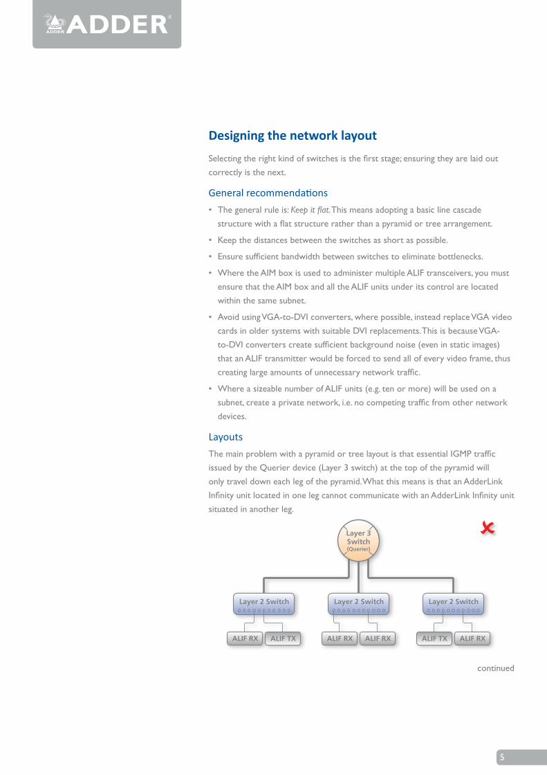
LayoutsThe main problem with a pyramid or tree layout is that essential IGMP traffic issued by the Querier device (Layer 3 switch) at the top of the pyramid will only travel down each leg of the pyramid. What this means is that an AdderLink Infinity unit located in one leg cannot communicate with an AdderLink Infinity unit situated in another leg.
Layer 2 Switch Layer 2 Switch Layer 2 Switch
ALIF RX ALIF RX ALIF TXALIF TX ALIF RX ALIF RX
Layer 3Switch(Querier)
continued
6
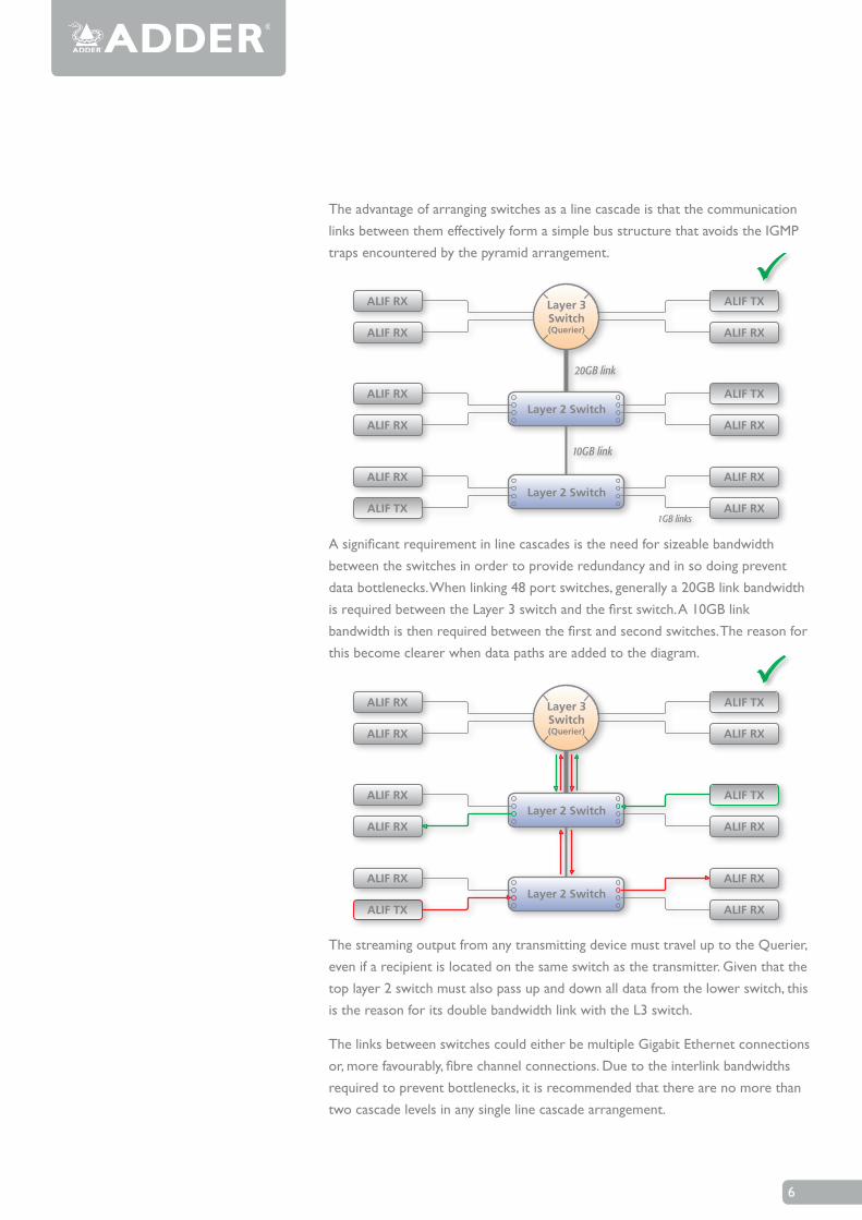
The advantage of arranging switches as a line cascade is that the communication links between them effectively form a simple bus structure that avoids the IGMP traps encountered by the pyramid arrangement.
Layer 2 Switch
Layer 2 Switch
20GB link
10GB link
1GB links
ALIF TX
ALIF RX
ALIF RX
ALIF RX
ALIF RX
ALIF RX
ALIF RX
ALIF TXALIF RX
ALIF RXALIF RX
ALIF TX
Layer 3Switch(Querier)
A significant requirement in line cascades is the need for sizeable bandwidth between the switches in order to provide redundancy and in so doing prevent data bottlenecks. When linking 48 port switches, generally a 20GB link bandwidth is required between the Layer 3 switch and the first switch. A 10GB link bandwidth is then required between the first and second switches. The reason for this become clearer when data paths are added to the diagram.
The streaming output from any transmitting device must travel up to the Querier, even if a recipient is located on the same switch as the transmitter. Given that the top layer 2 switch must also pass up and down all data from the lower switch, this is the reason for its double bandwidth link with the L3 switch.
The links between switches could either be multiple Gigabit Ethernet connections or, more favourably, fibre channel connections. Due to the interlink bandwidths required to prevent bottlenecks, it is recommended that there are no more than two cascade levels in any single line cascade arrangement.
ALIF TXALIF RX
ALIF RXALIF RX
Layer 2 Switch
Layer 2 Switch
ALIF TX
ALIF RX
ALIF RX
ALIF RX
ALIF RX
ALIF RX
ALIF RX
ALIF TX
Layer 3Switch(Querier)
7
Configuring switches and ALIFsThe correct configuration of each switch can have a significant impact on overall performance, so in this section we’ll take a look at the various issues. The precise configuration details for each switch vary with make and model, so please also check the Switch setups section where a selection of specific configuration details are made available for a limited number of common switches.
Enable IGMP snoopingIGMP snooping is an essential and effective tool to prevent multicast data from flooding the switches within a subnet. Ensure that IGMP snooping is enabled on every switch.
Ensure that the IGMP Fast-Leave option is enabled on all switches that have ALIF
units connected directly to them. This will allow the switches to respond quicker to changes in multicast arrangements.
As an alternative to IGMP, some Cisco switches also support a proprietary standard called CGMP (Cisco Group Management Protocol) which is not directly compatible with IGMP but achieves a similar outcome. CGMP sends multicast group messages at layer 2 and so switches can natively read these without needing to perform IGMP snooping. The use of CGMP is only possible if all of the switches within your network are Cisco units that support this standard.
Enable Jumbo frames (Jumbo packets)For the majority of video resolutions that are transmitted by ALIF units, standard Ethernet frame sizes are used to transfer video data quickly and efficiently.
However, certain video resolutions cause issues which require ALIF units to instead output Jumbo frames in order to correctly convey the necessary data. To efficiently handle these enlarged frames, the switches within the subnet need to have their Jumbo frames options enabled.
If any of the computers attached to your ALIF transmitters are using/or will use any resolution that uses 2048 horizontal pixels (e.g. 2048 x 1152), ensure that Jumbo frames are enabled on all of the switches within the subnet.
Enable Spanning Tree ProtocolMultiple and redundant links between switches are important for both transfer speeds and network resilience. However, unless carefully managed, such multiple links can cause bridge loops to occur and that is what the Spanning Tree Protocol (STP) is designed to prevent. However, that’s not the end of the story because STP can cause a new issue. It temporarily blocks newly found network links for
tens of seconds to ascertain their function, often causing problematic timeouts. This also causes a problem for device discovery when using AIM, whereby ALIF units cannot be correctly configured. Therefore, it is important to enable STP on every switch and also enable a technique known as portfast on every switch port that is not a link to another switch.
8
Choose the most appropriate switch forwarding modeEvery switch is built to transfer data from any one of its ports to any other as quickly as possible. Of the numerous factors involved to make this possible is the forwarding mode: the precise manner in which data packets are deciphered, checked and transferred.
For use with ALIF units, the Cut-through method generally produces the fastest results. However, if the network produces numerous data errors then it may be necessary to use a Store and forward mode instead. On higher grade switches, the latter should not impact performance too greatly.
Alter ALIF transmitter video settings, if necessaryWithin each ALIF transmitter there are various settings that affect the manner in which video is sent. Below is a brief summary of the common combinations. These settings can be accessed either through the transmitter tab of AIM or directly via the AdderLink Infinity browser-based configuration utility. Please refer to the relevant Adder user guides for details.
• If colour quality is important, then leave Colourdepth at 24 bits and adjust other controls,
• If moving video images are being shown frequently, then leave Frame Skipping at a low percentage and instead reduce the Peak bandwidth limiter and Colourdepth.
• Where screens are quite static, try increasing the Background Refresh interval and/or increasing the Frame skipping percentage setting.
Make changes one at a time, in small steps, and view typical video images so that you can attribute positive or negative results to the appropriate control.
Please refer to Glossary > ALIF transmitter video settings
Ensure that all ALIF units are fully updated Early versions of ALIF firmware (pre v2.1) exhibited an issue with the timing of IGMP join and leave commands that caused multicast flooding (i.e. network congestion) in certain configurations. Ensure that all ALIF units are fully updated to the latest firmware version.
TroubleshootingIf you encounter problems during installation or operation, please refer to the Troubleshooting section for possible remedies.
9
Problem: The video image of the ALIF receiver shows horizontal lines across the screen. This issue is known as Blinding because the resulting video image looks as though you’re viewing it through a venetian blind.
When video is transmitted by ALIF units, the various lines of each screen are divided up and transmitted as separate data packets. If the reception of those packets is disturbed, then blinding is caused. The lines are displayed in place of the missing video data packets.
There are several possible causes for the loss of data packets:
• Incorrectswitchconfiguration.Theproblem could be caused by multicast flooding, which causes unnecessary networktraffic.ThisiswhatIGMPsnooping is designed to combat, however, there can be numerous causes of the flooding.
• Speed/memorybandwidthissueswithinone or more switches. The speed and capabilities of different switch models varies greatly. If a switch cannot maintain pace with the quantity of data being sent through it, then it will inevitably start dropping packets.
• OneormoreALIFunitsmaybeoutputting Jumbo frames due to the video resolution (2048 horizontal pixels) being used. If jumbo frames are output by an ALIF unit, but the network switcheshavenotbeenconfiguredtouse jumbo frames, the switches will attempt to break the large packets down into standard packets. This process introduces a certain latency and could be a cause for dropped packets.
• OneormoreALIFunitsmaybeusinganoldfirmwareversion.Firmwareversionsprior to v2.1 exhibited an issue with the timing of IGMP join and leave commands that caused multicast flooding in certain configurations.
Remedies:
• EnsurethatIGMP snooping is enabled on all switches within the subnet.
• WhereeachALIFunitisconnectedasthe sole device on a port connection to a switch, enable IGMP Fast-Leave (aka Immediate Leave) to reduce unnecessary processing on each switch.
• Checkthevideoresolution(s)beingfed into the ALIF transmitters. If video resolutions with 2048 horizontal pixels are unavoidable then ensure that Jumbo frames are enabled on all switches.
• Checktheforwardingmodeontheswitches.IfStoreandforwardisbeingused, try selecting Cut-through as this mode causes less latency on lesser switch designs.
• EnsurethatonedevicewithinthesubnetiscorrectlyconfiguredasanIGMPQuerier, usually a multicast router.
• EnsurethatthefirmwareineveryALIFunit is version 2.1 or greater.
• Tryadjustingthetransmittersettingson each ALIF to make the output data streamasefficientaspossible.SeeAlter ALIF transmitter video settings if necessary for details.
Problem: The audio output of the ALIF receiver sounds like a scratched record.This issue is called Audio crackle and is a symptom of the same problem that produces blinding (see left). The issue is related to missing data packets.
Remedies:
As per blinding discussed above.
Problem: AIM cannot locate working ALIF units.There are a few possible causes:
• TheALIFunitsmustberesetbacktotheirzeroconfigIPaddressesforAIMdiscovery. If you have a working network of ALIF’s without AIM and then add AIM to the network, AIM will not discover the ALIFs until they are reset to the zero configIPaddresses.
• ThiscouldbecausedbyLayer2Ciscoswitches that have SpanningTreeProtocol(STP) enabled but do not also have portfast enabled on the ports to which ALIF units are connected. Without portfast enabled, ALIF units will all be assignedthesamezeroconfigIPaddressat reboot and AIM will only acquire them one at a time on a random basis.
You can easily tell whether portfast is enabledonaswitchthatisrunningSTP:When you plug the link cable from a working ALIF unit into the switch port, check how long it takes for the port indicator to change from orange to green. If it takes roughly one second, portfast is on; if it takes roughly thirty seconds then portfast is disabled.
Remedies:
• EnsurethattheALIFunitsandtheAIMbox are located within the same subnet. AIM cannot cross subnet boundaries.
• ManuallyresettheALIFunitstotheirzeroconfigIPaddresses.Pleaserefertothe ALIF user guide for details.
• Enableportfast on all switch ports that have ALIF units attached to them or try temporarilydisablingSTPontheswitcheswhile AIM is attempting to locate ALIF units.
Troubleshooting
continued
10
Troubleshooting
Problem: The mouse pointer of the ALIF receiver is slow or sluggish when moved across the screen.This issue is often related to either using dithering on the video output of one or more transmitting computers or using VGA-to-DVI video converters.
Dithering is used to improve the perceived quality and colour depth of images by diffusing or altering the colour of pixels between video frames. This practice is commonly used on Apple Mac computers using ATI or Nvidia graphics cards. VGA-to-DVI converters unwittingly produce a similar issue by creating high levels of pixel background noise.
ALIF units attempt to considerably reduce networktrafficbytransmittingonlythepixels that change between successive video frames. When dithering is enabled and/orVGA-to-DVIconvertersareused,this can have the effect of changing almost every pixel between each frame, thus forcing the ALIF transmitter to send the whole of every frame: resulting in greatly increasednetworktrafficandwhat’sperceived as sluggish performance.
Remedies:
•LinuxPCs
Check the video settings on the PC. If the Dither video box option is enabled, disable it.
• AppleMacwithNvidiagraphics
Use the Adder utility for Mac’s – Contact technical support.
• AppleMacwithATIgraphics
Use the ALIF 2000 series unit with Magic Eyeditherremovalfeature.
• WindowsPCs
If you suspect these issues with PC’s, contact technical support for assistance.
11
Internet Group Management ProtocolThe Internet Group Management Protocol (IGMP) is designed to prevent multicast flooding by allowing Layer 3 switches to check whether host computers within their care are interested in receiving particular multicast transmissions. They can then direct multicast data only to those points that require it and can shut off a multicast stream if the subnet has no recipients.
There are currently three IGMP versions: 1, 2 and 3, with each version building upon the capabilities of the previous one:
• IGMPv1 allows host computers to opt into a multicast transmission using a Join Group message, it is then incumbent on the router to discover when they no longer wish to receive; this is achieved by polling them (see IGMP Querier below) until they no longer respond.
• IGMPv2 includes the means for hosts to opt out as well as in, using a Leave Group message.
• IGMPv3 encompasses the abilities of versions 1 and 2 but also adds the ability for hosts to specify particular sources of multicast data.
AdderLinkInfinityunitsmakeuseofIGMPv2 when performing multicasts to ensure that no unnecessary congestion is caused.
IGMP Snooping
The IGMP messages are effective but only operate at layer 3 - intended for routers to determine whether multicast data should enter a subnet. A relatively recent development has taken place within the switches that glue together all of the hosts withineachsubnet:IGMPSnooping.IGMPsnooping means these layer 2 devices now have the ability to take a peek at the IGMP messages. As a result, the switches can then determine exactly which of their own hosts have requested to receive a multicast – and only pass on multicast data to those hosts.
IGMP Querier
When IGMP is used, each subnet requires one Layer 3 switch to act as a Querier. In this lead role, the switch periodically sends out IGMP Query messages and in response all hosts report which multicast streams they wish to receive. The Querier device and all snooping Layer 2 switches, then update their lists accordingly (the lists are also updated when Join Group and Leave Group (IGMPv2) messages are received).
IGMP Fast-Leave (aka Immediate Leave)
Whenadevice/hostnolongerwishestoreceive a multicast transmission, it can issue an IGMP Leave Group message as mentioned above. This causes the switch to issue an IGMP Group-SpecificQuerymessage on the port (that the Leave Group was received on) to check no other receivers exist on that connection that wish to remain a part of the multicast. This process has a cost in terms of switch processor activity and time.
Where ALIF units are connected directly to the switch (with no other devices on the same port) then enabling IGMP Fast-Leave mode means that switches can immediately remove receivers without going through a full checking procedure. Where multiple units are regularly joining and leaving multicasts, this can speed up performance considerably.
Jumbo frames (Jumbo packets)Sinceitscommercialintroductionin1980,theEthernetstandardhasbeensuccessfullyextended and adapted to keep pace with the ever improving capabilities of computer systems. The achievable data rates, for instance, have risen in ten-fold leaps fromtheoriginal10Mbit/stoacurrentmaximumof100Gbit/s.
While data speeds have increased massively,thestandarddefiningthenumberof bytes (known as the Payload) placed into each data packet has remained resolutely stuck at its original level of 1500 bytes. This standard was set during the original speedera(10Mbits/s)andofferedthebestcompromise at that speed between the time taken to process each packet and the time required to resend faulty packets due to transmission errors.
But now networks are much faster andfiles/datastreamsaremuchlarger;so time for a change? Unfortunately, a wholesale change to the packet size is not straightforward as it is a fundamental standard and changing it would mean a loss of backward compatibility with older systems.
Larger payload options have been around for a while, however, they have often beenvendorspecificandatpresenttheyremainoutsidetheofficialstandard.Thereis, however, increased consensus on an optional‘Jumbo’payloadsizeof9000bytesand this is fully supported by the AdderLink Infinity(ALIF)units.
Jumbo frames (or Jumbo packets) offer advantages for ALIF units when transmitting certain high resolution video signals across a network. This is because the increased data in each packet reduces the number of packets that need to be transferred and dealt with - thus reducing latency times.
The main problem is that for jumbo frames to be possible on a network, all of the devices on the network must support them.
Glossary
Glossary
12
Spanning Tree Protocol (STP)In order to build a robust network, it is necessary to include certain levels of redundancy within the interconnections between switches. This will help to ensure that a failure of one link does not lead to a complete failure of the whole network.
The danger of multiple links is that data packets, especially multicast packets, become involved in continual loops as neighbouring switches use the duplicated links to send and resend them to each other.
To prevent such bridging loops from occurring,theSpanningTreeProtocol(STP),operatingatlayer2,isusedwithineachswitch.STPencouragesallswitchestocommunicate and learn about each other. It prevents bridging loops by blocking newly discovered links until it can discover the nature of the link: is it a new host or a new switch?
The problem with this is that the discovery process can take up to 50 seconds before the block is lifted, causing problematic timeouts.
The answer to this issue is to enable the portfast variable for all host links on a switch. This will cause any new connection to go immediately into forwarding mode. However, take particular care not to enable portfast on any switch to switch connections as this can result in bridging loops.
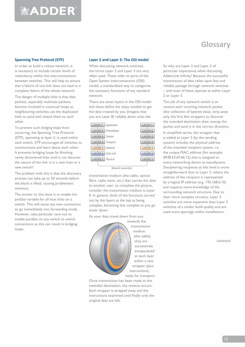
Layer 2 and Layer 3: The OSI modelWhen discussing network switches, the terms Layer 2 and Layer 3 are very often used. These refer to parts of the OpenSystemInterconnection(OSI)model, a standardised way to categorise the necessary functions of any standard network.
TherearesevenlayersintheOSImodelandthesedefinethestepsneededtogetthe data created by you (imagine that you are Layer 8) reliably down onto the
SowhyareLayer2andLayer3ofparticular importance when discussing AdderLinkInfinity?Becausethesuccessfultransmission of data relies upon fast and reliable passage through network switches – and most of these operate at either Layer 2 or Layer 3.
The job of any network switch is to receive each incoming network packet (the collection of layered data), strip away onlythefirstfewwrapperstodiscoverthe intended destination then rewrap the packet and send it in the correct direction.
Insimplifiedterms,thewrapperthatis added at Layer 2 (by the sending system) includes the physical address of the intended recipient system, i.e. the unique MAC address (for example, 09:f8:33:d7:66:12)thatisassignedtoevery networking device at manufacture. Deciphering recipients at this level is more straightforward than at Layer 3, where the address of the recipient is represented by a logical IPaddress(e.g.192.168.0.10)and requires more knowledge of the surrounding network structure. Due to their more complex circuitry, Layer 3 switches are more expensive than Layer 2 switches of a similar build quality and are used more sparingly within installations.
Glossary
LAYER 7 LAYER 7
LAYER 6 LAYER 6
LAYER 5 LAYER 5
LAYER 4 LAYER 4
LAYER 3 LAYER 3
LAYER 2 LAYER 2
LAYER 1 LAYER 1
Application
Presentation
Session
Transport
Network
Data Link
Physical
Network connection
transmission medium (the cable, optical fibre,radiowave,etc.)thatcarriesthedatato another user; to complete the picture, consider the transmission medium is Layer 0. In general, think of the functions carried out by the layers at the top as being complex, becoming less complex as you go lower down.
As your data travel down from you towards the
transmission medium (the cable), they are successively encapsulated at each layer within a new
wrapper (plus instructions),
ready for transport. Oncetransmissionhasbeenmadetotheintended destination, the reverse occurs: Eachwrapperisstrippedawayandtheinstructionsexamineduntilfinallyonlytheoriginal data are left.
continued
13
Protocols and portsIn order to achieve the feat of sending high resolutionDVIvideo,audio,RS232serialandfourUSBstreamsacrossastandardGigabitEthernetnetwork,ALIFunitsrelyupon a combination of industry standard protocols. These protocols operate at Layer 4 (the Transport layer) in the OSImodel, i.e. another level of sophistication above the Layer 2 and 3 techniques enacted by the switches and routers through which it travels.
TCP
TCP (Transmission Control Protocol) is a fundamental internetworking standard that allows a reliable data delivery route to be established between two hosts or devices. To ensure reliability of data transfer, TCP employs various techniques: Flow control to regulate data flow to suit the receiver, error detection to locate and replace corrupted packets, and congestion control to avoid swamping a busy network.
By their nature, the techniques employed for TCP connections impose a certain latency to the connections. For this reason, TCP is used by ALIF to handle the slightly less time-sensitive, but highly accuracy-sensitiveRS232serialandUSBdatalinks.
UDP
Like TCP, UDP (User Datagram Protocol) is a fundamental standard that provides a data route between hosts and devices. However, unlike TCP, it does not carefully regulatethelink.Oncesetup,dataissent to receiver(s) without knowledge of either their status or that of sent data. For this reason, UDP is totally unsuited for important control signals, however, it is ideal for data streams that can easily cope with the odd lost frame: video and audio. The great advantage of UDP is that its latency is minimal and it also allows one sender to communicate with more than one receiver. As such, UDP is a key component of multicasting.
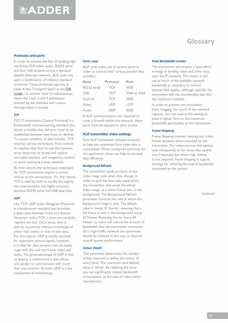
Ports used
ALIF units make use of various ports in order to achieve their various parallel data transfers:
Data Protocol Port
RS232serial TCP 3030
USB TCP 3040to3050
Control TCP 3000
Video UDP 1237
Audio UDP 3020
If ALIF communications are required to crossafirewallwithinthenetwork,theseports must be opened to allow access.
ALIF transmitter video settingsEachALIFtransmitterincludescontrolsto help you customise how video data is transmitted.Whenconfiguredcorrectlyforthe application, these can help to increase dataefficiency.
Background Refresh
The transmitter sends portions of the video image only when they change. In order to give the best user experience, the transmitter also sends the whole video image, at a lower frame rate, in the background. The Background Refresh parameter controls the rate at which this background image is sent. The default value is ‘every 32 frames’, meaning that a full frame is sent in the background every 32frames.Reducingthisto‘every64frames’ or more will reduce the amount of bandwidth that the transmitter consumes. Onahigh-trafficnetworkthisparametershould be reduced in this way to improve overall system performance.
Colour Depth
This parameter determines the number ofbitsrequiredtodefinethecolourofevery pixel. The maximum (and default) value is ‘24 bit’. By reducing the value youcansignificantlyreducebandwidthconsumption, at the cost of video colour reproduction.
Peak Bandwidth Limiter
The transmitter will employ a ‘best effort’ strategy in sending video and other data over the IP network. This means it will use as much of the available network bandwidth as necessary to achieve optimal data quality, although typically the transmitter will use considerably less than the maximum available.
In order to prevent the transmitter from ‘hogging’ too much of the network capacity, you can reduce this setting to place a tighter limit on the maximum bandwidth permissible to the transmitter.
Frame Skipping
FrameSkippinginvolves‘missingout’videoframes between those captured by the transmitter. For video sources that update only infrequently or for those that update veryfrequentlybutwherehighfidelityis not required, frame skipping is a good strategy for reducing the overall bandwidth consumed by the system.
Glossary
continued
14
Forwarding modesIn essence, the job of a layer 2 switch is to transfer as fast as possible, data packets arriving at one port out to another port as determined by the destination address. This is known as data forwarding and most switches offer a choice of methods to achieve this. Choosing the most appropriate forwarding method can often have a sizeable impact on the overall speed of switching:
• Store and forward is the original method and requires the switch to save each entire data packet to buffer memory, run an error check and then forward if no error is found (or otherwise discard it).
• Cut-through was developed to address the latency issues suffered by some store and forward switches. The switch begins interpreting each data packet as itarrives.Oncetheinitialaddressinginformation has been read, the switch immediately begins forwarding the data packet while the remainder is still arriving.Onceallofthepackethasbeenreceived, an error check is performed and, if necessary, the packet is tagged as being in error. This checking ‘on-the-fly’ means that cut-through switches cannot discard faulty packets themselves. However, on receipt of the marked packet, a host will carry out the discard process.
• Fragment-free is a hybrid of the above twomethods.Itwaitsuntilthefirst64bits have been received before beginning to forward each data packet. This way the switch is more likely to locate and discard faulty packets that are fragmented due to collisions with other data packets.
• Adaptive switches automatically choose between the above methods. Usually they start out as a cut-through switches and change to store and forward or fragment-free methods if large number of errors or collisions are detected.
Sowhichonetochoose?TheCut-through method has the least latency so is usually the best to use with AdderLink Infinityunits.However,ifthenetworkcomponentsand/orcablinggeneratealotof errors, the Store and forward method shouldprobablybeused.Onhigherendstore and forward switches, latency is rarely an issue.
Glossary
15
Cisco Catalyst 2960S and 3750Youneedtoconfigurethefollowingsettings:
• AssignswitchIPaddressanddefaultgateway
• AssignVLAN1withanIPaddress
• EnableIGMPsnooping
• EnableIGMPquerier
• EnableJumbopacketsandchoosetheMax setting.
• SetportfastforSTP
Assign switch IP address and default gateway
BeginninginprivilegedEXECmode,follow these steps to manually assign IP information to multiple switched virtual interfaces(SVIs).
1configureterminal
2 interface vlan 1
3 ip address <ip-address subnet-mask>
4 exit
5 ip default-gateway <ip-address>
6end
7showinterfacesvlan1
8 show ip redirects
9copyrunning-configstartupconfig
Assign VLAN1 with an IP address
1configureterminal
2 vlan 1
3 end
4copyrunning-configstartupconfig
Enabling IGMP snooping
BeginninginprivilegedEXECmodefollowthese steps to globally enable IGMP Snoopingontheswitch,firstgloballyandthen on VLAN1.
Globally:
1configureterminal
2 ip igmp snooping
3 end
4copyrunning-configstartup-config
On VLAN1:
1configureterminal
2 ip igmp snooping vlan 1
3 end
4copyrunning-configstartup-config
Enable IGMP querier
EnableIGMPQuerierusingthefollowingcommands in CLI mode
1configureterminal
2 ip igmp snooping querier
3 end
4 show ip igmp snooping vlan 1
5copyrunning-configstartup-config
Enable jumbo frames
EnableJumboframesandsetthesizetothemaximum(9000bytes).
1configureterminal
2systemmtujumbo9000
4 end
5copyrunning-configstartup-config
6reload
Enable STP portfast
1configureterminal
2 interface <interface-id>
3 spanning-tree portfast
4 end
5 show spanning-tree interface <interface-id> portfast
6copyrunning-configstartup-config
Cisco 6500ForCisco6500switches,portfast must be enabled for the initial device discovery process.
1Switch<config-if>#
2Switch<config-if>#spanning-treeportfast
Enable ip igmp snooping fast-leave
To enable IGMPv3-snooping fast-leave processing, use the ip igmp snooping fast-leavecommandininterfaceconfigurationmode. To disable fast-leave processing, use the no form of this command:
• ipigmpsnoopingfast-leave
• noipigmpsnoopingfast-leave
Syntax Description
This command has no arguments or keywords.
Defaults
The defaults are as follows:
• IGMPversion2-Disabled
• IGMPversion3-Enabled
Command Modes
Interfaceconfiguration
Command History
ReleaseModification
• 12.2(17d)SXB-SupportforthiscommandontheSupervisorEngine2wasextendedtoRelease12.2(17d)SXB.
• 12.2(33)SRA-ThiscommandwasintegratedintoCiscoIOSRelease12.2(33)SRA.
Usage Guidelines
This command is not supported on Cisco 7600seriesroutersthatareconfiguredwithaSupervisorEngine720.
EnterthiscommandinVLANinterfaceconfigurationmodeonly.
Switch setups
Switch setups
16
Extreme X460-24tYouneedtoconfigurethefollowingsettings:
•AssignVLAN1withanIPaddress
•EnableIGMPSnooping
•EnableIGMPFastLeave
•EnableJumbopacketsandsetthe size to the Max
Assign VLAN1 with an IP address
1 Connect a terminal or workstation running terminal emulation software to the console port, as detailed in “Using the Console Interface”.
2 At your terminal, press [Return] one or more times until you see the login prompt.
3 At the login prompt, enter your user name and password. The user name is not case-sensitive. The password is case-sensitive.Ensurethatyouhaveentered a user name and password with administrator privileges.
Ifyouarelogginginforthefirsttime,use the default user name admin to log in with administrator privileges. For example:
login: admin
Administrator capabilities enable you to access all switch functions. The default user names have no passwords assigned.
If you have been assigned a user name and password with administrator privileges, enter them at the login prompt.
4 At the password prompt, enter the password and press [Return].
When you have successfully logged in to the switch, the command line prompt displays the name of the switch.
5 Assign an IP address and subnetwork mask for the default VLAN by using the following command:
configure{vlan}<vlan_name>ipaddress[<ipaddress>{<ipNetmask>}|ipv6-linklocal|{eui64}<ipv6_address_mask>]
For example:
configurevlandefaultipaddress123.45.67.8255.255.255.0
The changes take effect immediately.
NOTE:Asageneralrule,whenconfiguringanyIPaddressesfortheswitch, you can express a subnet mask by using dotted decimal notation or by using classless inter domain routing notation (CIDR). CIDR uses a forward slash plus the number of bits in the subnet mask. Using CIDR notation, the command identical to the previous
Exampleis:
configurevlandefaultipaddress123.45.67.8/24
6Configurethedefaultroutefortheswitch using the following command:
configureiprouteadddefault<gateway>{<metric>}{multicast|multicast-only|unicast|unicast-only}{vr<vrname>}
For example:
configureiprouteadddefault123.45.67.1
7Saveyourconfigurationchangessothatthey will be in effect after the next switch reboot.
If you want to save your changes to the currentlybootedconfiguration,usethefollowing command:
save
ExtremeXOSallowsyoutoselectorcreateaconfigurationfilenameofyourchoicetosavetheconfigurationto.Ifyou want to save your changes to an existingornewconfigurationfile,usethefollowing command:
saveconfiguration[<existing-config>| <new-config>]
8Whenyouarefinishedusingthefacility,log out of the switch by typing:
logout or quit
Enable IGMP Snooping
To enable or disable IGMP snooping, use the following commands:
enableigmpsnooping{forward-mcrouter-only|{vlan}<name>|with-proxyvr<vrname>}
disableigmpsnooping{forward-mcrouter-only|with-proxy|vlan<name>}
Enable IGMP Fast Leave
EnablingandDisablingIGMPSnoopingFast Leave
To enable the fast leave:
enableigmpsnooping{vlan}<name>fast-leave
To disable the fast leave:
disableigmpsnooping{vlan}<name>fast-leave
Enable Jumbo packets and set the size to the Max
To enable jumbo frame support, enable jumbo frames on the desired ports. To set the maximum jumbo frame size, use the following command:
configurejumbo-frame-size<framesize>
The jumbo frame size range is 1523 to 9216.Thisvaluedescribesthemaximumsize of the frame in transit (on the wire), and includes 4 bytes of CRC plus another 4 bytes if 802.1Q tagging is being used.
SettheMTUsizefortheVLANbyusingthe following command:
configureip-mtu<mtu>vlan<vlan_name>
Switch setups
17
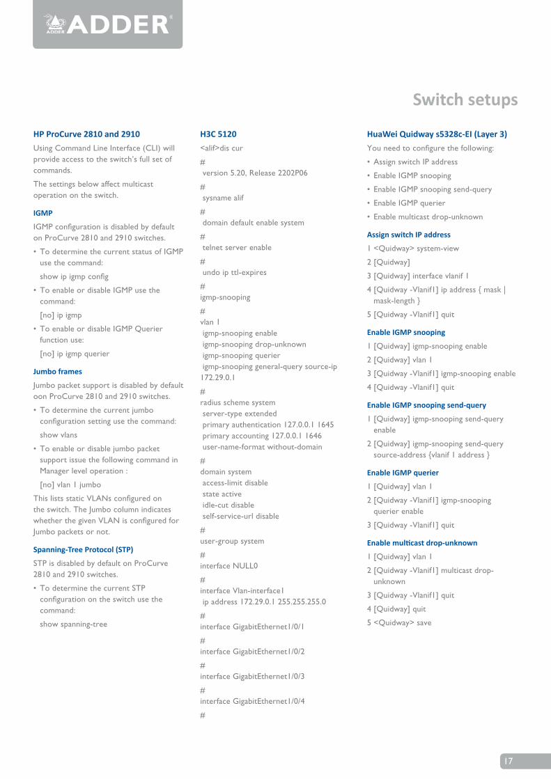
HP ProCurve 2810 and 2910Using Command Line Interface (CLI) will provide access to the switch’s full set of commands.
The settings below affect multicast operation on the switch.
IGMP
IGMPconfigurationisdisabledbydefaultonProCurve2810and2910switches.
• TodeterminethecurrentstatusofIGMPuse the command:
showipigmpconfig
• ToenableordisableIGMPusethecommand:
[no] ip igmp
• ToenableordisableIGMPQuerierfunction use:
[no] ip igmp querier
Jumbo frames
Jumbo packet support is disabled by default oonProCurve2810and2910switches.
• Todeterminethecurrentjumboconfigurationsettingusethecommand:
show vlans
• Toenableordisablejumbopacketsupport issue the following command in Manager level operation :
[no] vlan 1 jumbo
ThislistsstaticVLANsconfiguredonthe switch. The Jumbo column indicates whetherthegivenVLANisconfiguredforJumbo packets or not.
Spanning-Tree Protocol (STP)
STPisdisabledbydefaultonProCurve2810and2910switches.
• TodeterminethecurrentSTPconfigurationontheswitchusethecommand:
show spanning-tree
Switch setups
HuaWei Quidway s5328c-EI (Layer 3)Youneedtoconfigurethefollowing:
• AssignswitchIPaddress
• EnableIGMPsnooping
• EnableIGMPsnoopingsend-query
• EnableIGMPquerier
• Enablemulticastdrop-unknown
Assign switch IP address
1 <Quidway> system-view
2 [Quidway]
3 [Quidway] interface vlanif 1
4[Quidway-Vlanif1]ipaddress{mask|mask-length}
5 [Quidway -Vlanif1] quit
Enable IGMP snooping
1 [Quidway] igmp-snooping enable
2 [Quidway] vlan 1
3 [Quidway -Vlanif1] igmp-snooping enable
4 [Quidway -Vlanif1] quit
Enable IGMP snooping send-query
1 [Quidway] igmp-snooping send-query enable
2 [Quidway] igmp-snooping send-query source-address{vlanif1address}
Enable IGMP querier
1 [Quidway] vlan 1
2 [Quidway -Vlanif1] igmp-snooping querier enable
3 [Quidway -Vlanif1] quit
Enable multicast drop-unknown
1 [Quidway] vlan 1
2 [Quidway -Vlanif1] multicast drop-unknown
3 [Quidway -Vlanif1] quit
4 [Quidway] quit
5 <Quidway> save
H3C 5120<alif>dis cur
# version5.20,Release2202P06
# sysname alif
# domain default enable system
# telnet server enable
# undo ip ttl-expires
# igmp-snooping
# vlan 1 igmp-snooping enable igmp-snooping drop-unknown igmp-snooping querier igmp-snooping general-query source-ip 172.29.0.1
#radius scheme system server-type extendedprimaryauthentication127.0.0.11645primaryaccounting127.0.0.11646 user-name-format without-domain
#domain system access-limit disable state active idle-cut disable self-service-url disable
#user-group system
#interface NULL0
#interface Vlan-interface1ipaddress172.29.0.1255.255.255.0
#interfaceGigabitEthernet1/0/1
#interfaceGigabitEthernet1/0/2
#interfaceGigabitEthernet1/0/3
#interfaceGigabitEthernet1/0/4
#

18
Index
AAdaptive 14AIM 10ASIC3
BBackground refresh 8, 13Bandwidth6
CCGMP7Colourdepth 8Colour Depth 13Configuration
browser-based utility 8Cut-through 14
DDithering9
FFast-Leave9,11Forwarding modes 8, 14Fragment-free 14FrameSkipping8,13
GGroup-SpecificQuery11
IIGMP 11
Fast-Leave9,11Group-SpecificQuery11Immediate Leave 11Querier5,6,11Snooping3,9,11
Internet Group Management Protocol 11IP address 12
JJumboframes7,11Jumbopackets7,11
LLayer 2 and 3 12
MMAC address 12Multicasting 3Multicastrouter6
OOSImodel12
PPayload 11Peak bandwidth limiter 8, 13Portfast7Protocols 13
QQuerier5,6
SSnooping3,9SpanningTreeProtocol7,12Storeandforward14STP12Subnet5
TTCP 13Transmission Control Protocol 13
UUDP 13User Datagram Protocol 13
VVGA-to-DVI
converters5,9
Adder is a leading developer and manufacturer of KVM switches, video and audio extenders, KVM-over-IP devices, and remote management solutions. By empowering IT professionals to securely manage technology resources anywhere in the world, Adder solutions help customers make the best use of those resources while driving down total cost of ownership. In addition, through its advanced video and audio extension solutions, Adder is enabling the next generation of digital signage.
More information about Adder and its solutions is available at www.adder.com.
Europe
ADDER TECHNOLOGY,
Saxon Way, Bar Hill, Cambridge, CB23 8SL, UK
Telephone: +44 (0)1954 780044, Fax: +44 (0)1954 780081,
Email: [email protected]
ADDER BERLIN, Central & Eastern Europe,
Münchener Straße 4, 10777 Berlin, Germany
Telephone: +49 (0)30 8849 67-50, Fax: +49 (0)30 8849 67-48
Email: [email protected]
ADDER AMSTERDAM, BENELUX, FR, ES, IT, PT, GR, TK,
Crown Business Studios Aalsmeer, Kantoorunit 187, Van Cleeffkade 15, NL
Telephone: +31 (0)297 753625
Email: [email protected]
ADDER NORDIC,
Gamla Värmdövägen 8, 131 37 Nacka, Sweden
Telephone: +46 (8) 574 210 95, Fax: +46 (8) 574 211 95
Email: [email protected]
USA
ADDER CORPORATION,
350R Merrimac Street, Newburyport, MA 01950 USA
Telephone: 888-932-3337, Fax: 888-275-1117
Email us: [email protected]
Asia
ADDER TECHNOLOGY ASIA PACIFIC,
8 Burn Road, #04-10 Trivex, Singapore 369977
Telephone: +65 6288 5767, Fax: +65 6284 1150
Email: [email protected]
China
ADDER TECHNOLOGY LTD (China),
R225, BLD C, 327 TianYaoQiao Road, XuHui District, Shanghai, China 200030
Telephone: +86 (0)21 24193030, Fax: +86 (0)21 24193032
About Adder