Embed Size (px)
Citation preview

______________________________________________________________________________________
SuDS Design Requirements for LLFA Technical
AssessmentVersion 1.0
Issued as Living DRAFT 09/05/2016
This document sets out drainage information requirements, site specific considerations and what will be technically assessed by LLFA as part of planning application.
Shallow rain garden, Boyton Road, Haringey

______________________________________________________________________________________
Page: 2 of 26
Preface
As the Lead Local Flood Authority (LLFA), Haringey are a statutory consultee on Sustainable Drainage Systems (SuDS) to the Local Planning Authority (LPA) on all new major developments within the Borough. This document sets out the requirements that will be applied locally by the LLFA when undertaking a technical assessment of proposed SuDS schemes.
The purpose of this document is to provide guidance on design aspects that the LLFA will be reviewing as part of technical assessments.
This document will assist applicants through the planning submission and technical assessment process by:
Outlining when and how the LLFA will consult and provide advice within the overall framework of the planning process.
Identifying SuDS design criteria which will be applied within the Borough to ensure that the requirements of the FWMA and the Water Framework Directive (WFD) are upheld.
Providing guidance on aspects of SuDS design and calculation procedures to ensure that sufficient measures for flood protection / resilience and water quality are integrated.
Extensive guidance already exists in the industry to inform the development of SuDS design. The 2015 SuDS Manual was published in November 2015 and provides comprehensive design guidance. The 2015 SuDS Manual will remain a primary point of reference for Haringey LLFA when undertaking technical assessments and checking design submissions in relation to SuDS.
The non-statutory technical standards set out national requirements for delivering SuDS. These have been augmented by Haringey Local SuDS Standards, which are detailed in the Haringey Local Flood Risk Management Strategy (LFRMS) along with additional information on dealing with flood risk issues within the Borough.
The LLFA will look for reassurance as part of the technical assessment that SuDS proposals will minimise risk to the receiving environment and to the site. This assessment will consider aspects of flood risk and water quality relevant to LLFA.
SuDS, where designed a part of an integrated urban landscape, will also provide wider benefits such as make provision for amenity and provide opportunities for biodiversity. The delivery of these aspects of SuDS will be considered by the Local Planning Authority.

______________________________________________________________________________________
Page: 3 of 26
Table of Contents Preface ............................................................................................................................................................ 2
1. Introduction ............................................................................................................................................ 6
2. Why am I being asked to integrate SuDS into my planning proposal? ................................................... 7
3. Planning Application Process and SUDS Design ...................................................................................... 8
4. Technical Assessment of SuDS Design .................................................................................................... 9
4.1. SuDS Design principles .................................................................................................................... 9
4.2. Integrating SuDS as part of the urban landscape ......................................................................... 10
4.3. Collecting runoff ............................................................................................................................ 11
4.4. Conveying runoff ........................................................................................................................... 11
4.5. Discharging runoff ......................................................................................................................... 12
4.6. Infiltration – design considerations .............................................................................................. 13
4.7. Managing the rate of runoff ......................................................................................................... 13
4.8. Managing quantity / volume of runoff ......................................................................................... 16
4.9. Deriving attenuation storage volumes ......................................................................................... 17
4.9.1. Defining Coefficient of Volumetric Runoff (Cv) for Modified Rational Method ................... 17
4.9.2. Climate change and urban creep .......................................................................................... 18
4.9.3. Use of hydraulic modelling software .................................................................................... 18
4.9.4. Expressing hydraulic outputs ................................................................................................ 18
4.9.5. Designing flow controls ......................................................................................................... 19
4.10. Designing for exceedance and dealing with flows from off site ............................................... 21
4.11. Water quality treatment and pollution prevention .................................................................. 22
4.12. Structural Calculations for SuDS ............................................................................................... 22
4.13. Health and Safety ...................................................................................................................... 23
4.14. Maintenance ............................................................................................................................. 24
4.14.1. Managing and disposing of silt and waste from SuDS features ............................................ 24
Appendix A – Information requirements for Technical Assessment ............................................................ 25
Appendix B – Critical Drainage Areas ............................................................................................................ 26

______________________________________________________________________________________
Page: 4 of 26
List of Tables and Figures
Figure 1: Range of benefits from a SuDS Approach ........................................................................................ 6
Figure 2: Summary of information required by LLFA in respect to planning stages ...................................... 8
Figure 3: Assessing hierarchy of discharge ................................................................................................... 12
Figure 4: Approaches to determining GF discharge rate .............................................................................. 14
Figure 5: Examples of protected openings as part of flow control design ................................................... 19
Figure 6: Example of informative signage ..................................................................................................... 23
Table 1: Collecting flows at or near surface .................................................................................................. 11
Table 2: Runoff rates ..................................................................................................................................... 14
Table 3: Managing volume of runoff ............................................................................................................ 16
Table 4: Application of Urban Creep ............................................................................................................. 18
Table 5: Flow rates (l/s) relative to orifice sizes and depths of storage ....................................................... 19
Copyright notice
All images and text presented within this document are copyright of the authors and must not be
reproduced without the express permission of the authors (with the exception of images or text
specifically stated as being sourced from elsewhere).
Liability notice
Data and figures presented within this guide are intended to guide and facilitate design (therefore easing
the planning application and technical assessment process) and are to be used at the designers own risk.
Haringey accept no responsibility or liability for the failure of any design.

______________________________________________________________________________________
Page: 5 of 26
Glossary of general SuDS terms used within this document
The following glossary provides definitions of some of the technical terms used within this document.
Attenuation Reduction in the peak rate of runoff flowing from a site to an agreed rate. Flows are required to be temporarily stored on site.
Betterment An approach to reducing peak rates of runoff leaving a site.
Conveyance Movement of water from one location to another along a defined flow path.
Exceedance flows
Flood flows that might occur due to exceedance of design criteria or failure of any part of the system (including blockage), or other infrastructure.
Flow control A device used for the control the flow of water from an attenuation SuDS component, e.g. slot weir, orifice plate.
Infiltration The discharge of surface runoff into the ground.
Return period An estimate of the likelihood of an event. For example a 1 in 100 year return period has a 1% likelihood of occurrence within any particular year.
Site control Storage of runoff not contained by source control SuDS components but within the site boundary.
Source control The collection and control of runoff at or near where it falls on the surface of the development.
SuDS feature / technique / component
An element of the SuDS management train, e.g. a basin, swale, permeable pavement, rain garden, tank, green roof.
SuDS management train
A number of SuDS components which are linked in series to provide collection, conveyance, treatment and storage or runoff.
Sustainable Drainage System (SuDS)
An approach to managing rainfall in a manner that mimics nature. Individual or multiple linked drainage SuDS features designed to collect, attenuate, treat surface water runoff, and provide amenity and biodiversity benefits. The combination of benefits is referred to by the 2015 SuDS Manual as the four pillars of SuDS.

______________________________________________________________________________________
1. Introduction
SuDS (Sustainable Drainage Systems) is a relatively new approach used by the UK construction industry to managing rainfall and surface runoff using manmade drainage features (both natural and engineered) designed to mimic the natural drainage process. This approach has been successfully applied in other parts of Europe and worldwide over a number of decades. SuDS form a part of a design approach that strives to integrate water management with the needs of the environment and people in the built environment.
The SuDS approach needs to be considered early in the design process and integrated into the masterplan. As a result many benefits can be realised and the cost effectiveness of the drainage scheme enhanced.
Experiences in other parts of the UK have demonstrated that local residents consider developments with SuDS as desirable places to live. Well designed SuDS;
Are less expensive than the traditional drainage equivalent. When integrated throughout the development, improve resilience against flooding. Provide effective treatment, and require minimal maintenance.
Figure 1: Range of benefits from a SuDS Approach
SuDS
Benefits
Flood risk management
Water quality
management
Opportunity for
Biodiversity
Provision for Amenity
Recreation & Education
Capital & maintenance cost savings

______________________________________________________________________________________
Page: 7 of 26
2. Why am I being asked to integrate SuDS into my planning proposal?
The use of SuDS in future development and redevelopments has the potential to both enhance development and also reduce flood risk at the site and elsewhere. The ministerial statement released on 18 December 2014 fundamentally changed the way in which SuDS are considered within the planning system and states;
The Government’s expectation is that sustainable drainage systems will be provided in new developments wherever this is appropriate.
To this effect, we expect local planning policies and decisions on planning applications relating to major development - developments of 10 dwellings or more; or equivalent non-residential or mixed development (as set out in Article 2(1) of the Town and Country Planning (Development Management Procedure) (England) Order 2010) - to ensure that sustainable drainage systems for the management of run-off are put in place, unless demonstrated to be inappropriate. The current requirement in national policy that all new developments in areas at risk of flooding should give priority to the use of sustainable drainage systems will continue to apply.
Ensure through the use of planning conditions or planning obligations that there are clear arrangements in place for ongoing maintenance over the lifetime of the development.
Other documents also need consideration when developing SuDS design as outlined below;
The National Planning Policy Framework (NPPF) (http://tinyurl.com/o5s4ydt) -Paragraphs 103,109, 110 and 120; support the application of SuDS amongst other flood risk and water quality related matters. The Planning Practice Guidelines note that: “Sustainable drainage systems are designed to control surface water runoff close to where it falls and mimic natural drainage as closely as possible.” Designs should incorporate source control and keep rainfall runoff on or near the surface.
Haringey Local Development Plans and Local Flood Risk Management Strategy (LFRMS). These documents include Local SuDS Standards and requirements for SuDS delivery that must be adhered to and supplement the Non Statutory Technical Standards (http://tinyurl.com/q4gqo8t)
Specifically in relation to SuDS, the Haringey Development Management Development Planning Document (DPD) Policy DM25 states: The Council will require Sustainable Drainage Systems (SuDS) to be sensitively incorporated into new development by way of site layout and design, having regard to the following requirements: a) All major development proposals will be required to reduce surface water flows to a greenfield run-off rate for a 1 in 100 year critical storm event; b) All minor development proposals should aim to achieve a greenfield run-off rate and, at a minimum, achieve a 50 per cent reduction on existing site run-off rates; c) All other development should seek to achieve a greenfield run-off rate and include at least one ‘at source’ SuDS measure resulting in a net improvement in water quantity or quality discharging to a sewer; and d) For all development where a greenfield run-off rate cannot be achieved justification must be provided to demonstrate that the run-off rate has been reduced as much as possible.
These statements, policies and supporting guidance above provide a clear message that sustainable drainage must be included within scheme proposals.

______________________________________________________________________________________
Page: 8 of 26
3. Planning Application Process and SUDS Design
It is not anticipated that SuDS will be designed in considerable detail at concept stage. However, the key principles should have been given consideration at this point, otherwise SuDS may not be deliverable or at best may become cost prohibitive.
Information submitted for review should be proportionate to the planning application stage. For example the LLFA will not assess detailed calculations as part of Pre-application discussions. The information required for the SuDS assessment is identified within Appendix A and summarised in Figure 2.
Figure 2: Summary of information required by LLFA in respect to planning stages
For sites which require master-planning the following information will be required for assessment;
Details of phasing. Details of how flows will be managed and how storage of flows will be distributed across
the site (ideally each phase / plot will manage its own runoff rate and volume). Any requirements for regional facilities (and related conveyance SuDS components) and
confirmation on who would be responsible for construction and maintenance of these features.
•Discuss design constraints / parameters (including flood risk)
•Present flow route analysis and establish preferred method(s) of discharge
•Agree general design principles (collection of flow, subcatchments flow routes, treatment requirements, management train)
•Outline consent requirements and potential for adoption
•Discuss potential SuDS techniques, storage locations and maintenance requirements
Pre‐planning application discussion (Concept stage)
•Outline hydrology and hydraulic calculations, plans and design statement
•Where appropiate the LPA will pass to the LLFA for comment
•Method / permission to discharge to be confirmed.
•Maintanance arrangements to be confirmed
Outline planning permission
•Provide all required details for technical assessment (see Submission Validity Checklist ‐ Appendix A)
Detailed planning permission

______________________________________________________________________________________
Page: 9 of 26
4. Technical Assessment of SuDS Design
Haringey as the Lead Local Flood Authority (LLFA) and Risk Management Authority (RMA) will technically assess drainage applications for all major developments submitted for planning in relation to the following design aspects:
flood risk and mitigation; water quality and quantity; resilience of the system; long term maintenance considerations; climate change adaptation to flood risk and drought; health and safety implications.
Applicants should ensure they fulfil the requirements set out in the relevant Haringey planning policy and the LFRMS. The Technical Assessment will seek to establish;
The design meets criteria set out within the LFRMS, Local SuDS Standards, NSTS (http://tinyurl.com/q4gqo8t) and supplementary Practice Guidance (http://tinyurl.com/h5j6dcl).
SuDS features are integrated into the landscape of the site. How the SuDS management train delivers as a minimum; flood resilience, treatment of
runoff and exceedance flow routing where appropriate. The design is in keeping with the guidance provided by The 2015 SuDS Manual (C753)
(http://tinyurl.com/j3fwbfu) and BS8582:2013 (http://tinyurl.com/zrvc39p) . The level of detail applied to assessment is required as a minimum to be proportionate to the scale, nature and context of the site in relation to the wider drainage catchment. The following sections outline requirements that the LLFA will have with regard to SuDS design at various stages of the planning process. In particular, the LLFA will seek to ensure that appropriate design principles are applied.
4.1. SuDS Design principles
To ensure the effective delivery of SuDS schemes a number of design principles need to be considered at the start of the design process. The applicant should demonstrate consideration of the following SuDS principles as part of the design process, by detailing how design principles have been delivered within a concise design statement.
The SuDS Management Train (Image sourced from Susdrain)
______________________________________________________________________________________
Page: 10 of 26
Source control – Runoff should be dealt with as close as possible to where it falls Keeping runoff at or near the surface – Careful consideration is required when
determining how runoff will be collected and conveyed through the site. Subcatchments – Runoff from sites of reasonable size (for example, greater than 0.5ha)
should be managed sequentially within a number of subcatchments. The downstream point of each subcatchment will be defined by placement of a flow control and subcatchments linked in series as part of a management train.
Controlling flow – Flow controls should be designed so that they can be simply understood and easily accessible. No minimum threshold is set for the control of flows, however design should ensure that the flow control is protected from blockage.
Designing for exceedance – The design should demonstrate how exceedance flows will be dealt with in the event of design exceedance or blockage.
4.2. Integrating SuDS as part of the urban landscape
Dealing with runoff as part of a management train and integrating source control with exceedance routes through the site is preferred to ‘end of sewer storage’ approaches. To ensure cost effective delivery, SuDS design needs to be considered as part of the functional landscape of the site. Considerations for integrating SuDS as part of landscape design should include:
Understanding and use of site layout and levels; the landscape should serve a drainage function wherever possible.
Provision of green corridors; green / blue corridors through the site can provide flood exceedance routes allowing for increased flood resilience.
Site use and how it will function in practice; for example, soft landscaping SuDS features may get overrun from off street parking.
Choice of planting and tree selection. Designers should consider risk of blockage from leaf drop, and any requirements for retaining a vegetated ground cover whenever making plant selection.
Use of amenity space for storing runoff caused by extreme rainfall events. Multi-functional use of space will deliver cost savings to the developer. The design should demonstrate that depths of storage will not be excessive, that significant rainfall events can be managed safely and amenity space will be useable for its primary function for a large percentage of the time, in keeping with the principles set out in the Making Space for Water report. (http://tinyurl.com/zanrhl9)
Attenuation storage provided within permeable pavement and shallow grassed basin

______________________________________________________________________________________
Page: 11 of 26
The use of source control techniques slows down the flow of rainfall as soon as it occurs as runoff. Slowing flows assists with treatment processes such as sedimentation and increases retention time through the management train allowing more time for treatment of runoff. Other considerations for landscape design are outlined by C753.
As assessment of how SuDS are integrated with the overall site layout will form part of the technical assessment provided by Haringey.
4.3. Collecting runoff
A fundamental design consideration for SuDS relates to how runoff is collected. The use of gully pots or downpipes which take water into the ground may artificially increase the depth of the entire SuDS management train, which may inadvertently increase the cost of the SuDS installation. The 2015 SuDS Manual indicates that gully pots should not be considered as a form of treatment.
Flow can be collected at or near the surface using:
permeable surfaces,. design of kerbs to allow flows to runoff off the edge of the highway or use of chute gullies shoes at the bottom of downpipes to direct flows over the surface (designers may utilise
setts, channels or corduroy slabs to direct flow across impermeable surfaces to the SuDS component).
Table 1: Collecting flows at or near surface
Use of permeable pavement. Flows are collected and conveyed 300mm below surface
of the pavement.
Shallow surface channel formed using concrete setts taking flows from downpipe
across impermeable surface
4.4. Conveying runoff
There are numerous SuDS methods for conveying flows, for example; swales, permeable pavements, channels, filter drains plus many more. The use of short pipe runs to act as a connector under a highway between two SuDS components can also be used. All pipe runs should be easily rod-able and maintainable.

______________________________________________________________________________________
Page: 12 of 26
Where the depth of cover over any pipe is less than 1.2m in trafficked areas the pipe is likely to require a structural surround. Consultation is advised to agree an approach acceptable to Haringey Highways Services prior to detailed design commencing.
4.5. Discharging runoff
In the middle of dense urban areas such as Haringey there will be limited opportunities for discharge directly to watercourses. Most of Haringey is served by a separate foul and storm sewer system. Many of the storm sewers will discharge into one of the local watercourses such as the Moselle Brook. It is therefore important that designers have regard to both the quantity and quality of runoff discharging from development sites.
In additional many parts of Haringey have potential for infiltration. The British Geological Survey infiltration SuDS map (BGS 2015) is a useful source of information. Advice on small scale infiltration techniques within 5m of buildings if provided by a fact sheet located on www.susdrain.org (http://tinyurl.com/jgn3ftk)
To decrease the risk of flooding and environmental impact, applicants should seek to minimise the quantity of runoff from a site. Applicants should consider all potential means for reuse and minimisation of discharge of flows from a site.
Figure 3 outlines the options for discharge in order of how they should be considered. The applicant must demonstrate that they have considered each means of discharge in sequence in selecting the appropriate mean(s) of discharge.
Figure 3: Assessing hierarchy of discharge
In ensuring discharge will be permissible there may be a requirement for consent. Relevant consents should be obtained from the following:
Infiltration (Source Protection Zone (SPZ) areas or higher risk sites) - Environment Agency Ordinary watercourse – Haringey LLFA
Reuse Consider
Rain harvesting for toilet flushing, irrigation and other uses to reduce demand on water supply and quantity of runoff discharged from site.
Infiltration Consider
Infiltration potential, even if infiltration rates are low to reduce the volume of runoff from sites.
Watercourse Consider
Potential that the outlet may be drowned during flood conditions.
Requirements for Flood Defence Consent or Ordinary Watercourse Consent
Storm
sewer Consider
Existing capacity of the sewer.
Potential for surcharge conditions within the sewer. Elevated water levels within sewer may increase the volume of storage required.
Combined sewer Consider
Discharge to the combined sewer should not increase the risk of CSO spill.
Potential for surcharge of combined sewer flows into the drainage system.

______________________________________________________________________________________
Page: 13 of 26
Main watercourse - Environment Agency Highways drain – Haringey Highways Storm sewer – Thames Water Combined sewer – Thames Water Foul sewer – Discharge of storm runoff to the foul sewer will not be permitted.
4.6. Infiltration – design considerations
Wherever proposals are made to infiltrate some or all of the runoff from site, the applicant should demonstrate that they have given consideration to the following;
Has the ground potential for infiltration? What is the potential for surface runoff to contaminate local SPZ’s? Has the effectiveness of the design to provide treatment / removal of pollutants prior to the
infiltration feature been demonstrated? Will infiltrating cause an increased risk of instability within the underlying geology? Is the site situated on contaminated land? Is there sufficient depth between the base of the infiltration system and the ground water
table?
Any risks associated with infiltration should be appropriately assessed by a suitably qualified geotechnical engineer. It is noted that discussion will be required with EA where the site overlies Source Protection Zones 1 or 2 or where a significant risk of contamination is identified. SPZ areas are detailed on the EA website (http://tinyurl.com/j67cqup).
4.7. Managing the rate of runoff Any rainfall on the site which does not infiltrate will occur as runoff. As rainfall intensities increase the rate of runoff increases. The rate of runoff from developed impermeable areas will be significantly greater than pre-development permeable areas. In accordance with Haringey Development DPD Policy DM25, developments should ensure that there is no increase in flood elsewhere, and should seek to achieve Greenfield (GF) rates of runoff.
There are two approaches for setting the maximum allowable GF discharge rates as detailed in Figure 4 which depend on whether the volume of runoff can be managed (See Section 4.8).
IoH1241 and FSR are considered outdated methods for calculating runoff and rainfall. FEH data and methods are more up to date and should be used in preference for estimating rainfall and runoff. Rainfall data and local catchment hydrology characteristics for a site can be accessed here (http://tinyurl.com/hymp93g). The UK SuDS website (http://tinyurl.com/jkg76cd) provides initial estimation tools for Greenfield runoff and storage.
On larger schemes (greater than 0.5 hectares) the SuDS designer is encouraged to distribute storage across the site within defined subcatchments. In the event that one part of the system fails, through blockage of the flow control for example, the remainder of the drainage system will still provide storage. This will improve the overall resilience of the drainage system.
1 http://tinyurl.com/gn8az4u

______________________________________________________________________________________
Page: 14 of 26
Figure 4: Approaches to determining GF discharge rate
In applying the 50% betterment approach, the applicant should seek to establish the capacity of the existing drainage network (where this solely serves the site), with the aim of reducing flows discharging from the site via the drainage infrastructure by 50%. Where the existing capacity of the storm sewer network serving the site cannot determined then runoff rates should be limited to a maximum of 3 x GF rate for the respective return period.
The following table provides a guide to anticipated runoff rates for Haringey based on a clay soil using FEH methodology. Where soils are free draining and there are no constraints on infiltration, then it is anticipated that drainage scheme will be designed to infiltrate.
Table 2: Runoff rates
Return period Greenfield sites – allowable discharge rate (l/s/ha)
PDL sites – 3 times Greenfield runoff (l/s/ha)
**PDL sites 50% Betterment allowable discharge rate (l/s/ha)
1 in 1 year 3.4 10.2 8
1 in 2.year (Qmed) 4.0 12.0 20
1 in 30 year 9.3 27.9 63
1 in 100 year 12.9 38.7 63 **PDL 50% betterment rates are displayed on Table 2 for guidance purposes only. The applicant must demonstrate that they have calculated the capacity of the existing site drainage (i.e. drainage solely serving the site), upon which any allowable 50% Betterment rate will be based.

______________________________________________________________________________________
Page: 15 of 26
Figure 5: Previously Developed Land – defining a discharge rate
Box 1 ‐ Applying 50% betterment rates for PDL sites
In adherence with Policy DM25, 50% betterment rates can only be used on minor sites situated outside CDA areas. The LLFA will seek to reduce the overall level of flood risk within the CDA (DM26) by applying GF rates in all cases.
Greenfield runoff
rates provided by
design
Acceptable ‐ See figure 4 for
the appropriate setting of GF
rate
Capacity of existing
sewerage network
can be determined
Site is major
development
Site design to ensure that GF
runoff rates are achievable.
See Figure 4 for the
appropriate setting of GF rate
Site is situated
inside a CDA
Maximum allowable outflow
rate: 50% of existing sewerage
capacity. Volume of runoff
should not be increased.
Maximum allowable outflow rate: 3 x
GF runoff rate. Volume of runoff should
not be increased.
YES
NO
YES
YES
NO
YES
NO
NO

______________________________________________________________________________________
Page: 16 of 26
4.8. Managing quantity / volume of runoff
Development of areas which were previously permeable not only increases the rate of runoff, it also increases the overall quantity of runoff which unmanaged, can result in increased risk of flooding downstream. There are various ways to manage the additional volume of runoff generated which are briefly outlined below.
a. Rain harvesting - Where it can be demonstrated that the harvesting system will be in use for the majority of time and demand exceeds supply, a 50% allowance can be made against the long term storage volume requirements. (BS 8515:2009)
b. Interception - SuDS techniques which provide natural losses (e.g. soakage into topsoil and evapotranspiration) a 5mm reduction can be made on rainfall depths to account for interception losses. To demonstrate sufficient interception losses, the ratio of ‘SuDS space’ to ‘developed hard landscape’ should be a minimum of 1:4 (BS 8582:2013).
c. Infiltration - Where the system is unlined, even relatively low rates of infiltration can provide significant losses during the drain down period of the attenuation storage.
d. Separate area of storage - A separate area of storage can be provided which is filled from the attenuation system but from which outflow is controlled at a rate of 2 l/s/ha. This area of storage is unlikely to be used on a regular basis (i.e. it might only come into use to manage runoff from less frequently occurring rainfall events).
Table 3 provides an indication of the volume required to be managed using one (or combination) of the above methods to ensure that post development is no greater than that of existing.
Table 3: Managing volume of runoff
Soil Classification (WRAP Class)
m3/ha mm/m2
River terrace gravels, alluvium silts (2)
300 30
London Clay (4) 200 20
The increase in runoff volume generated by the site should be determined using the method detailed within C753 or suitable software. As a guide it is anticipated that on London Clay based sites, the increased quantity of runoff is anticipated to be approximately 200m3 for each additional hectare of development where permeable surfaces are developed as impermeable. This equates to 20 litres of additional runoff for every m2 of additional impermeable development.

______________________________________________________________________________________
Page: 17 of 26
4.9. Deriving attenuation storage volumes
To manage the additional rate and volume of surface runoff there will be a requirement to temporarily store water on site before discharge via infiltration or a flow control to a receiving sewer or watercourse (or a combination of both). As indicated by the NSTS there are two approaches for controlling flow rates leaving site via a flow control. Approach 1 - Where the additional volume of runoff generated by development is managed, the allowable discharge from attenuation storage will mimic the runoff conditions for the severity of storm. The rate of outflow will match the GF runoff rate for the respective rainfall return period. Approach 2 - Where additional volumes of runoff are not managed , discharge rates from the site will be capped to the 1 in 2year GF runoff rate for all storm events up to and including the 1 in 100 year +CC rainfall. Approach 1 results in lower overall storage volumes. However, where the additional volume of runoff cannot be managed, then Approach 2 must be adopted. It is important to consider design inputs such as Cv, climate change, urban creep and provisions for freeboard as these will impact on the volume of storage estimated and requirements on site.
4.9.1. Defining Coefficient of Volumetric Runoff (Cv) for Modified Rational Method
Cv attempts to represent the volume of flow from a particular surface and is used within the Modified Rational Method equation. For example, less runoff is likely to be generated from a grassed surface when compared to a paved or roofed surface. Values for Cv range from 0% (no runoff) up to 100% (i.e. all rainfall that falls on a surface occurs as runoff).
Box 2 ‐ Worked example– Managing the volume of runoff
On a site where the additional impermeable area was 0.5ha and based on London Clay the
additional volume of runoff of 100m3 (i.e. 200m3 / ha divided by 2). This additional runoff
could be dealt with by;
Interception losses – Assume 5mm losses x 5000m2 = 25m3 (demonstrated with
sufficient SuDS surfaces being available to produce losses)
Rain harvesting (50% allowance on 50m3 harvesting volume) = 25m3
Infiltration (low infiltration rate – system is unlined – slow rate infiltration losses
calculated during the drain down period as runoff is stored in attenuation features) =
65m3
Separate area designated as long term storage – not required
Total volume of runoff which is retained on site is (25+25+65=) 115m3. This exceeds 100m3

______________________________________________________________________________________
Page: 18 of 26
The designer must derive an appropriate Cv. The LLFA would typically anticipate a Cv of 0.95 from roofed areas and a Cv of 0.9 from other hard standing areas. These values should be applied for both summer and winter scenarios if using hydraulic design software. Consideration may be required to be given to runoff response from permeable areas on a site by site basis.
4.9.2. Climate change and urban creep
Climate Change - To account for climate change, rainfall intensities should be increased by intensity relevant at the time of submission with allowance made within conveyance and storage calculations. At the time of issue LBoH would recommend making allowance for 30% increase in rainfall intensities to allow for Climate Change with sensitivity testing carried out using 40% increase in rainfall intensities. Any reduction from DEFRA recommendations current at the time of making the application should be agreed as part of the pre-application discussion.
Urban Creep - On any low to medium density residential developments it is anticipated that ad-hoc extensions, additional driveways, and patio areas will increase the overall hardstanding area. The following table outlines the percentage increase to impermeable area which should be applied as part of attenuation calculation process.
Table 4: Application of Urban Creep
Residential development density - Dwellings per hectare ≤ 25 30 35 45 ≥ 50
Flats & apartments
Percentage of additional hardstanding area to be applied (as % of total proposed impermeable area)
10 8 6 4 2 0
4.9.3. Use of hydraulic modelling software
Use of hydraulic modelling software is not compulsory for submission. The designer should demonstrate that the methodology for deriving hydraulic outputs (i.e. flow rates, volumes, flow velocities and levels) is appropriate for the size, scale and nature of the site.
Haringey LLFA do not have a preference of hydraulic software where required to inform or validate design. Therefore for consistency of review during technical assessment it is required that the Flows and Volumes Proforma (Appendix A) is completed.
4.9.4. Expressing hydraulic outputs In using the Flows and Volumes Proforma for making submissions Design inputs and outputs should be expressed in a standard unit format and the volume / rate for the full site. This will enable benchmarking by the LLFA.
For example, using the guidance storage figures provided a development area (roofs and hardstanding) of 5000 m2 would require 325m3 of attenuation storage. This equates to 65mm/m2. The storage required per sq metre of development can be derived by dividing the site attenuation volume by the extent of developed impermeable areas.
______________________________________________________________________________________
Page: 19 of 26
4.9.5. Designing flow controls
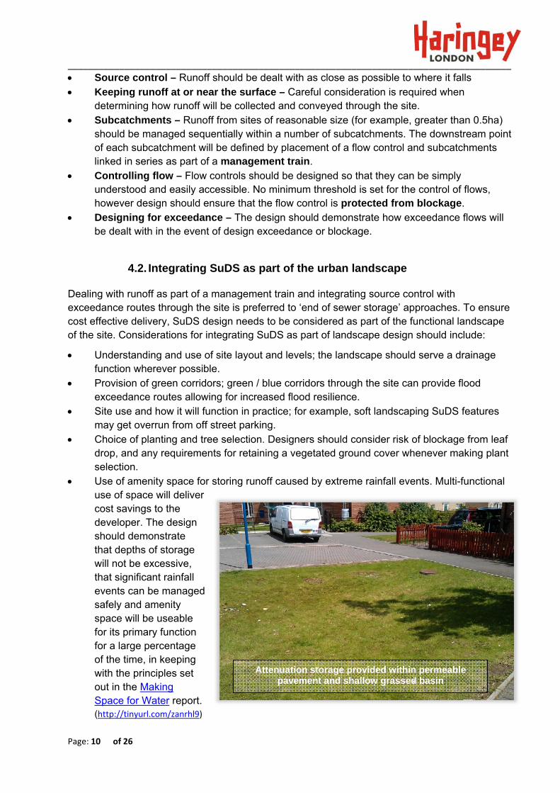
The LLFA expects flow controls to be designed so that they are protected from blockage by silt or floating debris, and are easily accessible for inspection and maintenance purposes from ground level regardless of the type of flow control used.
Figure 5: Examples of protected openings as part of flow control design
The following table provides an indication of the flow rates relative to orifice sizes and design head.
Table 5: Flow rates (l/s) relative to orifice sizes and depths of storage
Orifice diameter
Storage design head
0.15m 0.30m 0.45m 0.60m
20mm 0.4 0.5 0.6 0.7 30mm 0.8 1.1 1.4 1.6 40mm 1.4 2.0 2.5 2.9 50mm 2.1 3.1 3.9 4.5 60mm 3.0 4.5 5.6 6.5 70mm 4.0 6.0 7.5 8.8 80mm 5.1 7.8 9.8 11.4 90mm 6.3 9.8 12.3 14.4
100mm 7.6 11.9 15.1 17.7 The formula used to derive flow rates is: Q = CA √2gH Where: A = Cross sectional area of the orifice. H = Depth to the centre of the orifice (free discharge is assumed). C = Coefficient of Discharge. A coefficient of 0.62 is assumed for a

______________________________________________________________________________________
Page: 20 of 26
square edged inlet. The outlet is assumed to be freely discharging (i.e. not subject to drowning or surcharge).
For a 1 hectare site flows are required to be
controlled to the following rates:
1 in 1 year 3.4 l/s
1 in 100 year 12.9 l/s
Depths of storage are assumed as 150mm and
450mm for 1 in 1 year and 1 in 100 year return
periods respectively.
1 in 1 year – use 60mm opening set at base of
storage, with 150mm depth of storage for 1 in 1 year,
which provides 3.0 l/s outflow (from Table 3).
1 in 100 year – 60mm opening for 600mm depth of
storage provides outflow rate of 6.5 l/s (from Table
3). Allowable discharge is 12.9l/s. Therefore 12.9 –6.5
= 6.4 l/s. The additional 6.4 l/s discharge will be
provided by an additional opening which will only
operate once the 1 year storage is utilised.
Using an additional 65mm opening with invert
150mm above invert of lower orifice (600 – 150 =
450mm design head) provides 6.5 l/s outflow (This
figure is calculated and not taken from table).
6.5 + 6.5 = 13.0 l/s
Therefore design outflows of 3.4 and 12.9 l/s are
reasonably matched for 1 in 1 year and 1 in 100 year
rainfall return periods using specified depths of
storage. Further detailed analysis with hydraulic
modelling software can be used to achieve a closer
match with required flow rates as required.
Box 3 ‐ Worked example– Using an orifice plate to control rate of flow
Schematic of how the orifice plate might appear
150mm ‐1 in
1 yr
storage dep
th
450mm design
head
for 2nd orifice
600mm – total dep
th of storage‐ 1 in
100 year rainfall even
t
60mm dia
opening
65mm dia
opening
Other methods for controlling flow are available and will be reviewed as
part of technical assessment. Key design considerations must include
provision to protect the opening and reduce the risk of blockage.
______________________________________________________________________________________
Page: 21 of 26
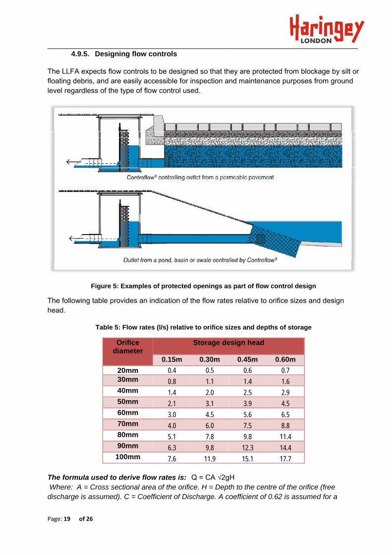
The following image illustrates a flow control which is protected by using a rock filled stainless steel gabion basket over the outlet (prior to the flow control chamber). It is an existing site located on Rain garden Boyton Road, Haringey.
Example of rain garden outlet designed to protect flow control from blockage
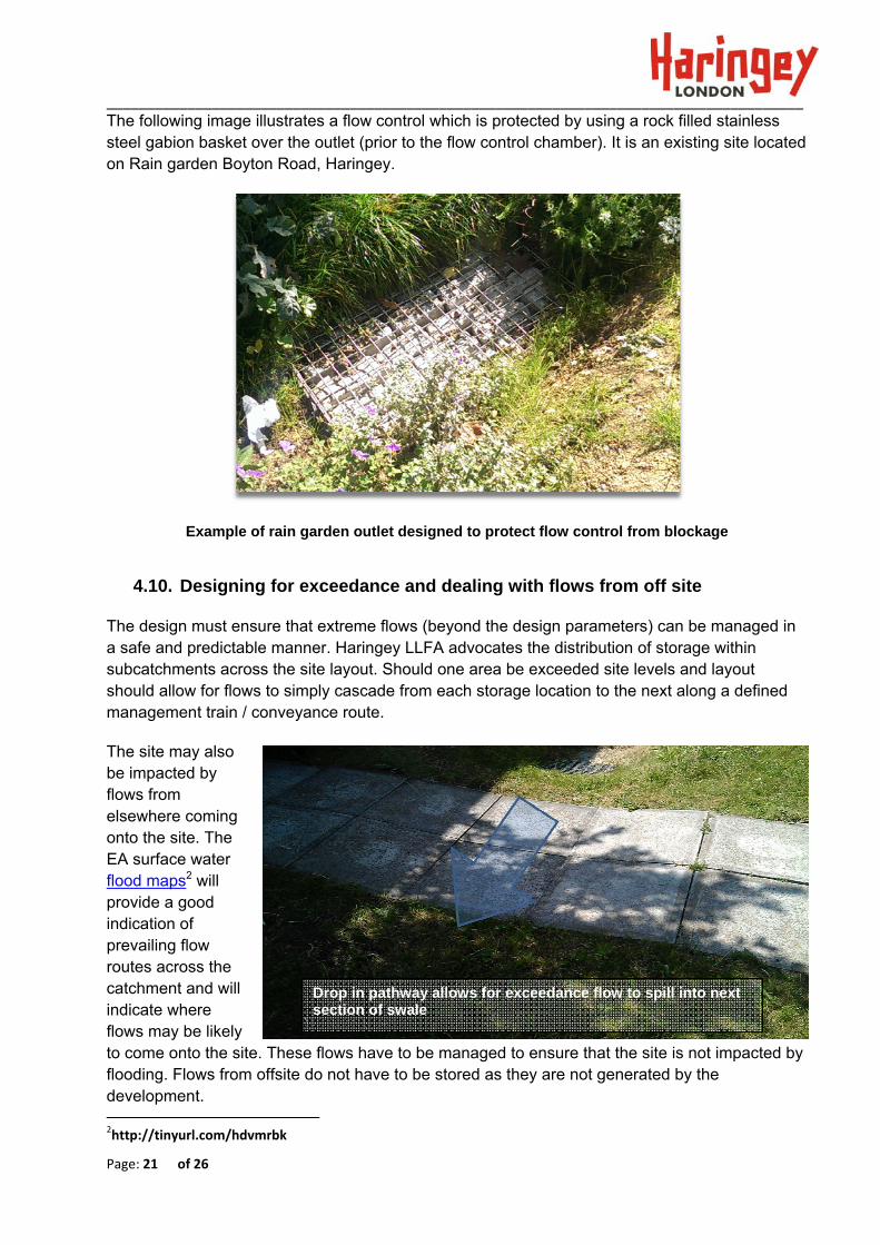
4.10. Designing for exceedance and dealing with flows from off site
The design must ensure that extreme flows (beyond the design parameters) can be managed in a safe and predictable manner. Haringey LLFA advocates the distribution of storage within subcatchments across the site layout. Should one area be exceeded site levels and layout should allow for flows to simply cascade from each storage location to the next along a defined management train / conveyance route.
The site may also be impacted by flows from elsewhere coming onto the site. The EA surface water flood maps2 will provide a good indication of prevailing flow routes across the catchment and will indicate where flows may be likely to come onto the site. These flows have to be managed to ensure that the site is not impacted by flooding. Flows from offsite do not have to be stored as they are not generated by the development. 2http://tinyurl.com/hdvmrbk
Drop in pathway allows for exceedance flow to spill into next section of swale

______________________________________________________________________________________
Page: 22 of 26
4.11. Water quality treatment and pollution prevention
Drainage of sites must not impact on the water quality of the receiving water body (groundwater or surface water). These requirements are enforced by the Water Framework Directive.
Applicants will be required to assess the risk of contaminates being generated from the site and the sensitivity to the receptor (surface water or ground water). The 2015 SuDS Manual provides guidance on the risk assessment procedure.
The level of detail required for Water Quality risk assessment will depend on the likely pollutant loading over a range of pollutants and the sensitivity of the receptor. As the approach to Water Quality risk assessment is subjective Haringey will assess whether a sufficient degree of rigor has been applied by the design of mitigation. Haringey LLFA / LPA encourage the use of SUDS techniques which breakdown organic pollutants passively using natural processes. This will reduce the ongoing maintenance costs where specific interventions may otherwise be required for the removal of organic pollutants. Careful consideration should be given to the placement of SuDS techniques along the management train. Wetlands and ponds are important biodiversity and amenity features which cope better with controlled flow of relatively clean water. Therefore LBoH’s preference sis for runoff to receive treatment and initial storage upstream of these types of SuDS features.
4.12. Structural Calculations for SuDS
Structural calculations should fully consider the anticipated loading (and frequency of loading) both during construction and the projected design life of the project.
The following resources are identified as best practice and LLFA will look to see that these are complied with as part of the technical assessment (where appropriate).
Box 4 ‐ Water Quality and pollution prevention Design Principles
Keeping runoff at or near the surface enables natural bio‐degradation processes.
Effective treatment will include different pollution removal processes generally using
different types of SuDS techniques.
Keeping flow at the surface allows for easy identification of spillage and subsequent
containment and removal.
Discussions should be held with EA for any sites which are deemed higher risk (SPZ zones or
brownfield sites with contamination risk).

______________________________________________________________________________________
Page: 23 of 26
Permeable pavement - BS 7533 , 2015 SuDS Manual, Interpave website Structural design of modular geocellular drainage tanks (C680D) All relevant structural concrete design codes
Applicants should note that propriety products having BBA certification will not be accepted in lieu of structural calculations.
4.13. Health and Safety
Health and safety considerations are integral to all aspects of design. Whether or not the design will incorporate open surface water features may depend on the characteristics of the site. For example, high density sites might promote the use of permeable surfaces. Designers should demonstrate that the design has fully considered health and safety aspects for construction and operation, in addition to use of the scheme by the general public.
The following is provided as guidance when undertaking a risk assessment for SuDS features:
Provision for toddlers – consideration in areas where toddlers may be unsupervised. Toddler fencing is nominally 0.6m high and constructed from pails rather than rails.
Placement of hard engineering structures in relation to standing water (potential for concussion and falling into open water). Hard engineered structures should be set back 1m from permanent water edge. Headwalls should be built on the slope rather than having a vertical face.
Allowance for safe and easy access / egress from open SuDS features. Side slopes should be retained to a maximum of 1 in 3.
Systems should be easy to maintain, preferably without any requirement for man entry into confined spaces.
Permanent water depths within ponds should be no greater than 0.6m. Maximum water depths within open water features (whenever the 1 in 100 year runoff is being stored) should generally be no greater than 1.2m.
Provision of ‘danger deep-water’ signs is not considered a mitigation of risk. Information boards informing the public of the benefits of the SuDS scheme and the presence and depth of any permanent or temporary open water should conveyed as an informative message on signage provided at the site.
Figure 6: Example of informative signage

______________________________________________________________________________________
Page: 24 of 26
4.14. Maintenance
Haringey will require maintenance details to review as part of the technical assessment. Maintenance details should outline the activities and the recommended frequency of occurrence for each activity.
Maintenance for the following should be identified generally as follows: Regular day-to-day care, including Litter removal, Grass cutting, Checking inlets and
outlets; Occasional tasks including, silt management, management of aquatic and woody
vegetation, and maintenance of flow control structures; Provision for remedial works in the event of; Erosion – damage by water, Spillage –
damage by chemicals, Vandalism – damage by people, Removal of invasive species.
This list is not exhaustive and specific maintenance requirements may be required, particularly where propriety products are included within the design. Maintenance manuals should be concise, clearly set out and accompanied with a key plan identifying the locations of key maintenance duties.
If drainage structures are not proposed to be adopted, the on-going maintenance for the life of the scheme, ownership of the structure and responsible party or owners details are required to be provided to Haringey for inclusion on its Drainage Asset database.
4.14.1. Managing and disposing of silt and waste from SuDS features
Well designed SuDS will capture silts within the source control techniques. Environment Agency permits the deposit and dewatering of non-hazardous silt from Sustainable Drainage Systems on land which is as close as possible to the point where the waste was produced (with no requirement for an environmental permit) as long as the following requirements are met:
The total quantity of waste silts deposited or treated over any 12 month period does not exceed 5 cubic metres per hectare of development served by the SUDS;
Any silts generated from roofs, residential roads, parking areas and commercial areas will not require analysis. Silts generated from refuse collection, industrial areas, loading bays, lorry parks and highways will require analysis to establish how they should be disposed of (along with any necessary environmental permitting).

______________________________________________________________________________________
Appendix A – Information requirements for Technical Assessment

Drainage Application Validity Checklist Page 1 of 2
Drainage Application Validity Checklist
The LLFA Technical Assessment will focus on the quantity and quality aspects of surface runoff management within developments. To allow a full understanding of design philosophy design inputs and outputs are requested to be presented by applicants prior to assessment. The following list is not exhaustive and other specific information may be required on a case by case basis. Some elements listed are required for LPA assessment (and will not be reviewed by LLFA) but have been listed here for completeness. It is presumed that design inputs will be established by the applicant prior to design being fully progressed. Design inputs:
1. Drainage design criteria agreed with London Borough of Haringey LPA and LLFA - with supporting reference to Development Management DPD, Haringey SuDS – Guide to requirements for LLFA technical Assessment, London Drainage Action Plan, Non-Statutory Technical Standards; Streetscene Manual for Haringey (specific surface treatment materials); requirements for multi-functional use of SuDS space and design objectives for sustainability (including climate resilience).
2. Details of existing site surface water drainage infrastructure and ownership established
3. Confirmation that the relevant consents are in place (or can be obtained) ; Flood defence Consent (Environment Agency) for any structures within 9 meters of a main river, Ordinary Watercourse Consent (LLFA) for any structure with the potential to affect flows in an ordinary watercourse, or with Sewerage Undertaker for any connections to the public sewer.
4. Topographical survey of the site
5. Ground investigation, including infiltration test results, soil testing, groundwater monitoring (as appropriate).
6. Survey of existing surface water infrastructure condition and capacity calculations (only where 50% betterment rates are proposed).
7. Coordinated constraints map identifying all potential design constraints including areas of flood risk (fluvial, pluvial, surface water and ground water), contaminated land, archaeological significance, poor ground conditions, UXOs (and any other constraints that may impact on the delivery of the scheme).
8. Existing utility services drawing.
9. List of design criteria to be adhered to; for example, rainfall return periods, discharge allowance, traffic loading requirements etc.
10. Summary of findings from flood risk assessment
11. Related conditions from LPA (how open space across the site should be used for example)
Design outputs:
1. Design statement explaining how SuDS will operate.
2. Haringey LLFA Proformas completed (Flows and Volumes and Design Checklist).
Drainage Application Validity Checklist Page 2 of 2
3. Drawing of Drainage catchment areas showing permeable and impermeable areas (for pre and post proposed development). Drainage catchment areas should take account of site levels)
4. Plan of site and proposed drainage system detailing flow routes (including exceedance flow routes), subcatchment boundaries, flow control locations, storage locations, contributing impermeable area, (phasing where appropriate);
5. Design calculations which demonstrate compliance with the design criteria for the site. (including all hydraulic and structural calculations)
6. Detailed site layout at an identified scale (1:200 or 1:500 or as appropriate or any other scale agreed) including a North direction arrow. SuDS components to be provided in GIS format to Haringey LLFA requirements.
7. Long sections and cross sections for the proposed drainage system, including surrounding site level and proposed finished floor levels (where appropriate)
8. Construction Details – inlets, outlets, flow controls, storage, edge details, connection details to receiving watercourse/ sewers / public surface water sewers / highway drains;
9. Details of any offsite works required, together with any necessary consents;
10. Maintenance plan and management strategy - Confirmation of access arrangements for all proposed drainage systems; Plans for adequate maintenance arrangements are in place and confirmed
11. Landscape planting schedule
12. Construction programme (identifying when SuDS will be constructed)
13. Construction drainage management plan - Plan for management of runoff during construction and construction impacts including any diversions, erosion control, phasing and defects maintenance period (pre-adoption);
14. Designers hazard and risk assessment. To consider construction, maintenance / operation by personnel and day to day site use by public.
15. Proposed maintenance schedule and confirmed management arrangements for all non adopted drainage; Identify any proposed split of the SuDS between private (cartilage) and public (open space or highway) land.
16. Details of any informative signage proposed for SuDS.
17. Any required cost estimates for construction and long term maintenance.
For a large site or multi-plot development:
Applicants to provide the following (if not already contained within the drainage strategy or sustainable drainage design code):
1. Full details of individual development plot discharge and storage constraints;
2. Full details of responsibility for controlling the overall surface water management
of the site.

Site Name ‐ xxxxxxxxxxxxx Date design review completed ‐ 08/03/2016
Page 1 of 10 Haringey LLFA TECHNICAL ASSESSMENT AUDIT SHEET
LLFA TECHNICAL ASSESSMENT - DESIGN CHECKLIST Planning application reference …Sample application ref…………………………………… Site name …Sample site - to demonstrate how form should be completed… Check ref
Design Check Description Justification for check Response from Applicant (example text shown)
Comment from LLFA (example text shown)
Design approach
LLFA DC1
Have all design parameters / site constraints been investigated. Examples include‐ Flood extents / depths (fluvial and surface water) Ground water level Presence of contamination Presence of existing services Proposed site use Presence of SPZ Sensitivity of receiving waterbody Archaeology constraints
Adopted Policy London Plan: 5.13 Sustainable Drainage; Haringey: SP5 Water management and flooding Emerging Policy Haringey: DM24 Managing & Reducing Flood Risk; DM25 Sustainable Drainage Systems
Site and existing constraints have been appraised and are detailed within the design statement and associated drawings. There are existing services located at the site and known presence of contamination. The site is not impacted by river flooding. Site is proposed for residential use.
Response accepted

Site Name ‐ xxxxxxxxxxxxx Date design review completed ‐ 08/03/2016
Page 2 of 10 Haringey LLFA TECHNICAL ASSESSMENT AUDIT SHEET
Check ref
Design Check Description Justification for check Response from Applicant (example text shown)
Comment from LLFA (example text shown)
LLFA DC2
Have flow routes through the site been identified? This should include the management of flow routes from offsite. (FRA should identify potential flow routes from offsite and onsite)
Mitigate risk of onsite flooding to properties/infrastructure and downstream features Local Standards ‐ LS9a Adopted Policy London Plan: 5.13 Sustainable Drainage; Haringey: SP5 Water management and flooding Emerging Policy Haringey: DM24 Managing & Reducing Flood Risk; DM25 Sustainable Drainage Systems
Flow routes have been analysed and are detailed on DWGxxxx.
Flows route drawing checked considered reasonable to deal with flows generated onsite. The site is located within a CDA. The applicant should consider the potential for exceedance flows from upslope coming on to the site. Flows from off site do not need to be attenuated but need to be managed in such a way that site is suitably protected in terms of flood risk.
LLFA DC3
Is SuDS attenuation / long term storage located outside Q100 fluvial floodplain? (NOTE – Haringey SFRA / site specific FRA should identify flood extents) Provision of SuDS attenuation or long term storage within floodplain extents will not be accepted without the express agreement with LLFA.
Adopted Policy London Plan: 5.13 Sustainable Drainage; Haringey: SP5 Water management and flooding Emerging Policy Haringey: DM24 Managing & Reducing Flood Risk; DM25 Sustainable Drainage Systems
Yes – The site is no encroached of the site boundary by theQ100 floodplain. FRA indicates potential risk of surface water flooding. This will be managed as part of site drainage design.
Response accepted. The site is within a CDA and therefore outflow rates must be controlled to equivalent Greenfield runoff rates.

Site Name ‐ xxxxxxxxxxxxx Date design review completed ‐ 08/03/2016
Page 3 of 10 Haringey LLFA TECHNICAL ASSESSMENT AUDIT SHEET
Check ref
Design Check Description Justification for check Response from Applicant (example text shown)
Comment from LLFA (example text shown)
LLFA DC4
How has design exceedance been catered for?
To prevent on site and downstream flooding. Provide safe exit routes from the site. Local Standards ‐ LS9b Adopted Policy London Plan: 5.13 Sustainable Drainage; Haringey: SP5 Water management and flooding Emerging Policy Haringey: DM24 Managing & Reducing Flood Risk; DM25 Sustainable Drainage Systems
The flow route analysis demonstrates that if one permeable pavement compartment overtops, flows will flow over surface to the next area of permeable pavement. Site is relatively flat and exceedence flows are designed to be held within carriageway / paved areas to a low depth (less than 150mm) and low velocity (less than 1m/s)
Response accepted.

Site Name ‐ xxxxxxxxxxxxx Date design review completed ‐ 08/03/2016
Page 4 of 10 Haringey LLFA TECHNICAL ASSESSMENT AUDIT SHEET
Check ref
Design Check Description Justification for check Response from Applicant (example text shown)
Comment from LLFA (example text shown)
LLFA DC5
Has the potential for infiltration been investigated. Consideration to be given to infiltration rates, SPZs, presence of contamination and ground water table level.
Local Standards – LS4, LS5 and LS6 Adopted Policy London Plan: 5.13 Sustainable Drainage; Haringey: SP5 Water management and flooding Emerging Policy Haringey: DM24 Managing & Reducing Flood Risk; DM25 Sustainable Drainage Systems DM27 Protecting and Improving Groundwater Quality and Quantity
The Site investigation identified slow rates of infiltration (1x10^‐7m/s). Permeable pavement areas will be unlined with exception of isolated areas where downpipes discharge to permeabl pavement. Slow rate infiltration will be utilised to manage volumes of flow discharging from the site allowing the design to utilise variable outflow rates up to the outflow rate for the SI does not identify the presence of contaminates which are likely to be mobilised. The site does not overlie a SPZ.
Response accepted

Site Name ‐ xxxxxxxxxxxxx Date design review completed ‐ 08/03/2016
Page 5 of 10 Haringey LLFA TECHNICAL ASSESSMENT AUDIT SHEET
Check ref
Design Check Description Justification for check Response from Applicant (example text shown)
Comment from LLFA (example text shown)
LLFA DC6
Is Source Control provided Increased flood resilience. Maximise potential for interception losses. Local Standards ‐ LS4, LS5, LS15 DM24 Managing & Reducing Flood Risk; DM25 Sustainable Drainage Systems
The site is subdivided into 3 subcatchments which form a management train with storage allocated in each subcatchment. Flows are passed from final permeable pavement compartment into a small open water canal feature. Flow control is situated at the passforward point from each subcatchment controlling the rate of flow through the site.
Drawing and design statement has been reviewed and approach considered acceptable. Permeable pavement will not be adopted by LBoH and Application should make provision of long term maintenance requirements
LLFA DC7
Has the potential for spillage been considered?
Protecting and enhancing the water environment of the catchment (WFD) Local Standards ‐ LS15, LS16 Adopted Policy London Plan: 5.13 Sustainable Drainage; Haringey: SP5 Water management and flooding Emerging Policy Haringey: DM25 Sustainable Drainage Systems Haringey: DM27 Protecting and Improving Groundwater Quality and Quantity
The site is considered to be low risk in terms of pollution risk . Discharge is to storm water pipe (and onwards to watercourse). Low rates of infiltration demonstrate that any major spillage can ve captured at flow control chambers. Management plan contains environmental emergency response plan. Calculations have been completed as per updated SuDS Manual C753 demonstrating that sufficient day to day treatment is provided.
Response accepted.

Site Name ‐ xxxxxxxxxxxxx Date design review completed ‐ 08/03/2016
Page 6 of 10 Haringey LLFA TECHNICAL ASSESSMENT AUDIT SHEET
Check ref
Design Check Description Justification for check Response from Applicant (example text shown)
Comment from LLFA (example text shown)
LLFA DC8
Does the depth of storage in open water features meet health and safety requirements?
CDM Adopted Policy London Plan: 5.13 Sustainable Drainage; Haringey: SP5 Water management and flooding Emerging Policy Haringey: DM24 Managing & Reducing Flood Risk; DM25 Sustainable Drainage Systems
One open water feature (small canal) is proposed on site. Depth will be shallow (450mm max) and side slopes allow for access and egress. There are no confined spaces proposed. A Hazard Identification and risk assessment is attached with submission.
Response accepted
Calculations
LLFA DC9
Time taken for 50% of attenuation storage to drain down less than 24 hours?
To ensure adequate capacity is available within the system to accommodate subsequent rainfall events Local Standards – LS2b, LS3a, LS3b.
The half empty time is 12 hours. Software calculations have been undertaken and results are detailed in Haringey Flows and Volumes Proforma.
Response accepted.
LLFA DC10
Have critical durations been determined for storage calculations?
Ensure adequate attenuation Local Standards – LS2b, LS3a, LS3b.
A range of rainfall durations are assessed from 15minutes to 2 days. Worst case volume is adopted for design. Results are detailed in Haringey Flows and Volumes Proforma.
Response accepted.

Site Name ‐ xxxxxxxxxxxxx Date design review completed ‐ 08/03/2016
Page 7 of 10 Haringey LLFA TECHNICAL ASSESSMENT AUDIT SHEET
Check ref
Design Check Description Justification for check Response from Applicant (example text shown)
Comment from LLFA (example text shown)
LLFA DC11
Check for drowned outlet / flow control.
Ensure Flood resilience Emerging Policy Haringey: DM24 Managing & Reducing Flood Risk;
Flood levels within watercourse have been checked. These do not influence levels on site. Permeable pavement holds runoff within 500mm of surface therefore storage is unlikely to be impacted by drowned outlet / flow control.
Response accepted pending consideration of potential of surcharge within storm sewer affecting storage calculations. LLFA will advise whether this is a potential risk (this does not confer liability and Applicant should carry out their own sensibility check).
LLFA DC12
Consideration / allowance for urban creep
Local Standards ‐ LS2b Urban creep is not anticipated. Response not accepted. Development is housing. Applicant should consider application of percentage increase outlined in ‘Guide to SuDS requirements for LLFA Technical assessment’
LLFA DC13
Erosion check To ensure longevity of the drainage system and no undue maintenance requirements. Local Standards ‐ LS2b (potential for blockage)
Site is high density. All SuDS components are based on hard landscape. Canal contains subsoil and vegetation, however flows are controlled prior to entry to canal. Erosion is not anticipated.
Response accepted.
Site Name ‐ xxxxxxxxxxxxx Date design review completed ‐ 08/03/2016
Page 8 of 10 Haringey LLFA TECHNICAL ASSESSMENT AUDIT SHEET
Check ref
Design Check Description Justification for check Response from Applicant (example text shown)
Comment from LLFA (example text shown)
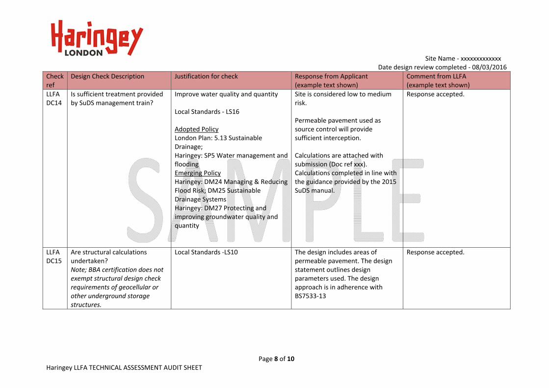
LLFA DC14
Is sufficient treatment provided by SuDS management train?
Improve water quality and quantity Local Standards ‐ LS16 Adopted Policy London Plan: 5.13 Sustainable Drainage; Haringey: SP5 Water management and flooding Emerging Policy Haringey: DM24 Managing & Reducing Flood Risk; DM25 Sustainable Drainage Systems Haringey: DM27 Protecting and improving groundwater quality and quantity
Site is considered low to medium risk. Permeable pavement used as source control will provide sufficient interception. Calculations are attached with submission (Doc ref xxx). Calculations completed in line with the guidance provided by the 2015 SuDS manual.
Response accepted.
LLFA DC15
Are structural calculations undertaken? Note; BBA certification does not exempt structural design check requirements of geocellular or other underground storage structures.
Local Standards ‐LS10 The design includes areas of permeable pavement. The design statement outlines design parameters used. The design approach is in adherence with BS7533‐13
Response accepted.

Site Name ‐ xxxxxxxxxxxxx Date design review completed ‐ 08/03/2016
Page 9 of 10 Haringey LLFA TECHNICAL ASSESSMENT AUDIT SHEET
Check ref
Design Check Description Justification for check Response from Applicant (example text shown)
Comment from LLFA (example text shown)
LLFA DC16
Has the appropriate allowance for Climate Change been applied
Local Standards ‐LS2b The storage design includes a 30% allowance for climate change. This was agreed at pre‐app meeting with LLFA.
Response accepted.
Design Detailing and delivery
LLFA DC17
Does the storage volumes calculated match the provision made on drawings? Note; careful consideration to be given to levels along shallow storage devices.
Sensibility check Design is as per hydraulic calculations. Levels have been checked on drawings.
Response accepted pending check as outlined below. A low point has been identified on DWG xxx which may impact on effective storage provision. Applicant to ensure that low point does not impact on hydraulic design.
LLFA DC18
How has the design ensured that flow controls they are protected to minimise risk of blockage. Flow controls and openings may be prone to blockage, design should consider potential for blockage by silt and floating debris.
Improved flood resilience. Local standard – LS9b Emerging Policy Policy Haringey: DM24 Managing & Reducing Flood Risk; DM25 Sustainable Drainage Systems
The flow controls are design withprotected openings. Flows controls are placed within chambers and recieve flows from permeable pavement. Permeable pavement will filter out silt and litter removing risk of flow control blockage. Final flow control from canal is design as a protected opening as per Haringey SuDS design Guide.
Response accepted.
Site Name ‐ xxxxxxxxxxxxx Date design review completed ‐ 08/03/2016
Page 10 of 10 Haringey LLFA TECHNICAL ASSESSMENT AUDIT SHEET
Check ref
Design Check Description Justification for check Response from Applicant (example text shown)
Comment from LLFA (example text shown)
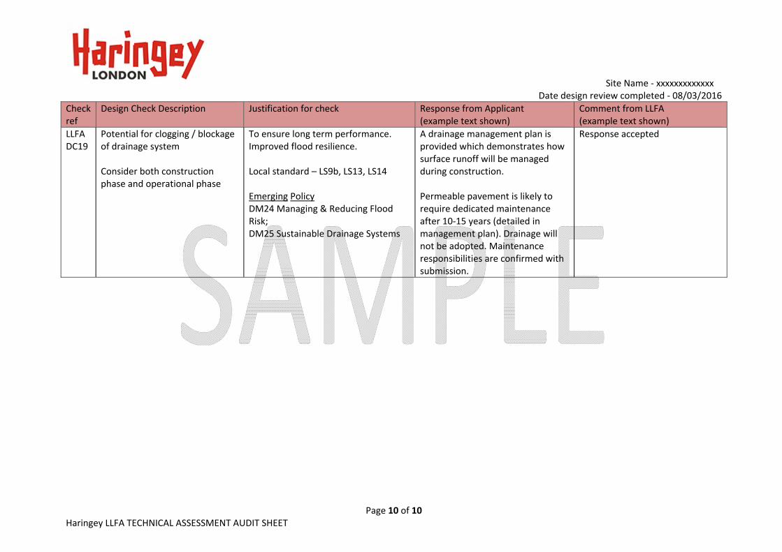
LLFA DC19
Potential for clogging / blockage of drainage system Consider both construction phase and operational phase
To ensure long term performance. Improved flood resilience. Local standard – LS9b, LS13, LS14 Emerging Policy DM24 Managing & Reducing Flood Risk; DM25 Sustainable Drainage Systems
A drainage management plan is provided which demonstrates how surface runoff will be managed during construction. Permeable pavement is likely to require dedicated maintenance after 10‐15 years (detailed in management plan). Drainage will not be adopted. Maintenance responsibilities are confirmed with submission.
Response accepted

SuDS Flows and Volumes – LLFA Technical Assessment Proforma
Revision 1.2 – Issued June 2015
This form identifies the information required by Haringey LLFA to enable technical assessment of flows and volumes determined as part of drainage / SuDS calculations. Note : * means delete as appropriate; Numbers in brackets refer to accompanying notes. SITE DETAILS 1.1 Planning application reference …Sample site …………………… 1.2 Site name …Greenfield site………………………………………………… 1.3 Total application site area (1) ……10,000…m2 …………………1…ha VOLUME AND FLOW DESIGN INPUTS 2.1 Site area which is positively drained by SuDS (2) …10,000…m2 2.2 Impermeable area drained pre development (3) ……0… m2 2.3 Impermeable area drained post development (3) …10,000…m2
2.4 Additional impermeable area (2.3 minus 2.2) …10,000…m2 2.5 Predevelopment use (4) Greenfield / Brownfield / Mixed* 2.6 Method of discharge (5) Infiltration / waterbody / storm sewer / combined sewer* 2.7 Infiltration rate (where applicable) ………0.001…m/hr 2.8 Influencing factors on infiltration ……………Clay site.......................................... 2.9 Depth to highest known ground water table…………………………mAOD 2.10 Coefficient of runoff (Cv) (6) ……0.9 Paved, 0.95 Roofed…… 2.11 Justification for Cv used ……As Per LBoH Guidance......................................... 2.12 FEH rainfall data used (Note that FSR is no longer the preferred rainfall calculation method) Y/N 2.13 Will storage be subject to surcharge by elevated water levels in watercourse / sewer Y/N 2.14 Invert level at outlet (invert level of final flow control) ...…99.5…mAOD 2.15 Design level used for surcharge water level at point of discharge(14)…99.0…mAOD

SuDS Flows and Volumes – LLFA Technical Assessment Proforma
Revision 1.2 – Issued June 2015
CALCULATION OUTPUTS Sections 3 and 4 refer to site where storage is provided by attenuation and / or partial infiltration. Where all flows are infiltrated to ground omit Sections 3 -5 and complete Section 6. 3.0 Defining rate of runoff from the site 3.1 Max. discharge for 1 in 1 year rainfall …3.4…l/s/ha, …3.4…l/s for the site 3.2 Max. discharge for Qmed rainfall ……4.0…l/s/ha, …4.0……l/s for the site 3.3 Max. discharge for 1 in 30 year rainfall ……9.3…l/s/ha, …9.3……l/s for the site 3.4 Max. discharge for 1 in 100 year rainfall …12.9…l/s/ha, …12.9……l/s for the site 3.5 Max. discharge for 1 in 100 year plus 30%CC ……12.9…l/s/ha, ……12.9…l/s for the site 4.0 Attenuation storage to manage peak runoff rates from the site 4.1 Storage - 1 in 1 year 215m3 …0.021m3/m2 (of developed impermeable area) 4.2 Storage - 1in 30 year (7) 577m3 …0.057m3/m2
4.3 Storage - 1in 100 year (8) 817m3 …0.082m3/m2
4.4 Storage - 1 in 100 year plus 30%CC (9) 1102m3 …0.110m3/m2 5.0 Controlling volume of runoff from the site 5.1 Pre development runoff volume(10) …280 m3 for the site 5.2 Post development runoff volume (unmitigated) (10) …480 m3 for the site 5.3 Volume to be controlled/does not leave site (5.2 - 5.1)…200 m3 for the site 5.4 Volume control provided by
- Interception losses(11) 150m3 - Rain harvesting(12) NA - Infiltration (even at very low rates) 72m3 - Separate area designated as long term storage(13) NA
5.5 Total volume control (sum of inputs for 5.4) 222m3 (15) 6.0 Site storage volumes (full infiltration only) 6.1 Storage - 1in 30 year (7) ………m3 ………m3/m2 (of developed impermeable area) 6.2 Storage - 1 in 100 year plus CC (9) ………m3 ………m3/m2

SuDS Flows and Volumes – LLFA Technical Assessment Proforma
Revision 1.2 – Issued June 2015
Notes
1. All area with the proposed application site boundary to be included. 2. The site area which is positively drained includes all green areas which drain to the SuDS system and
area of surface SuDS features. It excludes large open green spaces which do not drain to the SuDS system.
3. Impermeable area should be measured pre and post development. Impermeable surfaces includes, roofs, pavements, driveways and paths where runoff is conveyed to the drainage system.
4. Predevelopment use may impact on the allowable discharge rate. The LLFA will seek for reduction in flow rates to GF status in all instances. The design statement and drawings explain / demonstrate how flows will be managed from the site.
5. Runoff may be discharge via one or a number of means. 6. Sewers for Adoption 6th Edition recommends a Cv of 100% when designing drainage for impermeable
area (assumes no loss of runoff from impermeable surfaces) and 0% for permeable areas. Where lower Cv’s are used the application should justify the selection of Cv.
7. Storage for the 1 in 30 year must be fully contained within the SuDS components. Note that standing water within SuDS components such as ponds, basins and swales is not classified as flooding. Storage should be calculated for the critical duration rainfall event.
8. Runoff generated from rainfall events up to the 1 in 100 year will not be allowed to leave the site in an uncontrolled way. Temporary flooding of specified areas to shallow depths (150-300mm) may be permitted in agreement with the LLFA.
9. Climate change is specified as 30% increase to rainfall intensity, unless otherwise agreed with the LLFA / EA.
10. To be determined using the 100 year return period 6 hour duration rainfall event. 11. Where Source Control is provided Interception losses will occur. An allowance of 5mm rainfall depth
can be subtracted from the net inflow to the storage calculation where interception losses are demonstrated. The Applicant should demonstrate use of subcatchments and source control techniques.
12. Please refer to Rain harvesting BS for guidance on available storage. 13. Flow diverted to Long term storage areas should be infiltrated to the ground, or where this is not
possible, discharged to the receiving water at slow flow rates (maximum 2 l/s/ha). LT storage would not be allowed to empty directly back into attenuation storage and would be expected to drain away over 5-10 days. Typically LT storage may be provided on multi-functional open space or sacrificial car parking areas.
14. Careful consideration should be used for calculations where flow control / storage is likely to be influenced by surcharged sewer or peak levels within a watercourse. Storm sewers are designed for pipe full capacity for 1 in 1 to 1 in 5year return period. Beyond this, the pipe network will usually be in conditions of surcharge. Where information cannot be gathered from Thames Water, engineering judgement should be used to evaluate potential impact (using sensitivity analysis for example).
15. In controlling the volume of runoff the total volume from mitigation measures should be greater than or equal to the additional volume generated.

______________________________________________________________________________________
Page: 26 of 26
Appendix B – Critical Drainage Areas

54 Development Management DPD Haringey’s Local Plan54
Cha
pter
04:
EN
VIR
ON
ME
NTA
L S
US
TAIN
AB
ILIT
YFIG
UR
E 4
.5
C
riti
cal D
rain
age
Are
as