Embed Size (px)
Citation preview
By Martin A. Taylor and Charles L. Kimtantas
[email protected] & [email protected]
Bechtel Hydrocarbon Technology Solutions. Inc.
3000 Post Oak Blvd, Houston, Texas 77056
Sulfur Capacity
Expansion OptionsINFRASTRUCTURE
MINING & METALS
NUCLEAR, SECURITY & ENVIRONMENTAL
OIL, GAS & CHEMICALS
© 2016 BechtelLevel 4 - Bechtel Public
� Introduction
� Sulfur plant basics� Hydrocarbon minimization� Pressure drop minimization
� Ammonia recovery� Oxygen addition
� Sulfur dioxide
� Tail gas compression� Conclusions
Overview
© 2015 Bechtel | 2 Level 4 - Bechtel Public
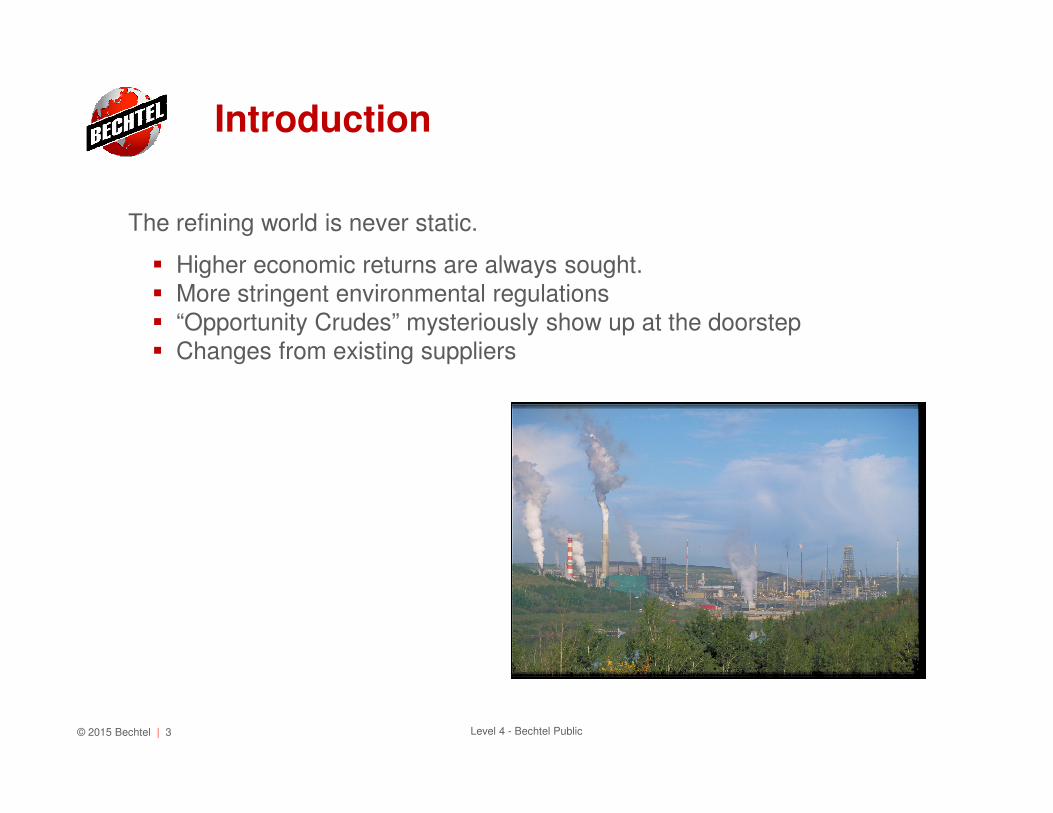
The refining world is never static.
� Higher economic returns are always sought.
� More stringent environmental regulations
� “Opportunity Crudes” mysteriously show up at the doorstep� Changes from existing suppliers
Introduction
© 2015 Bechtel | 3 Level 4 - Bechtel Public
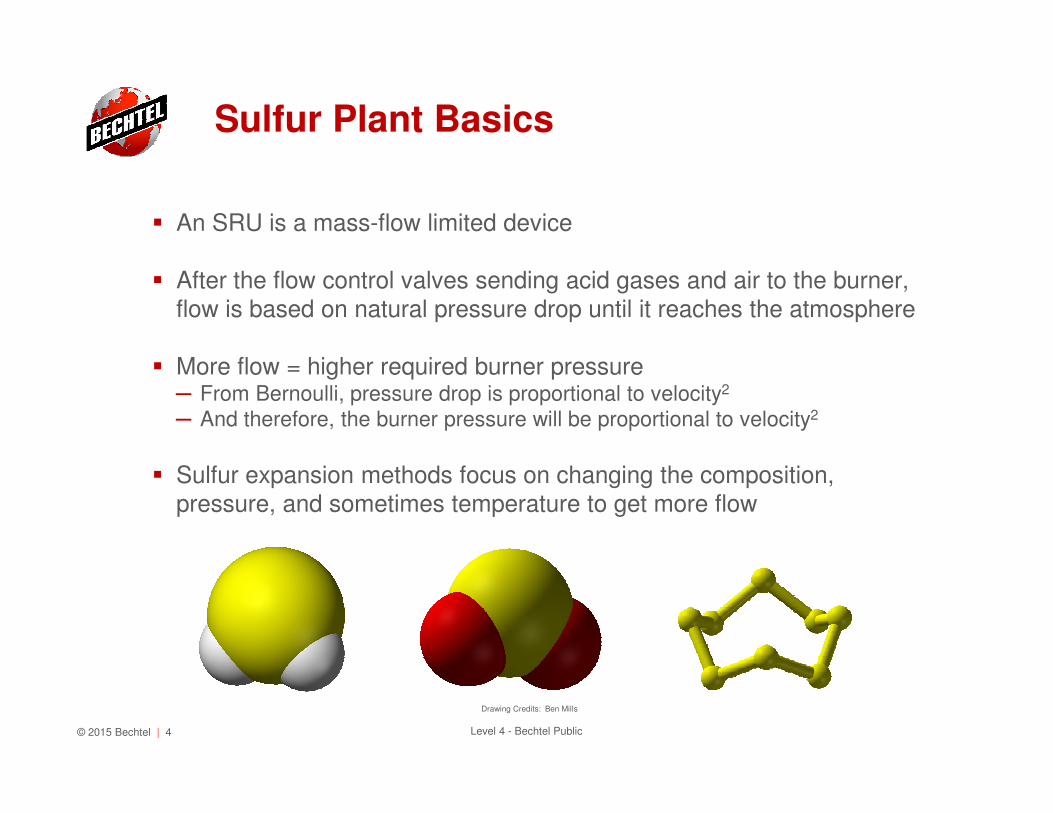
� An SRU is a mass-flow limited device
� After the flow control valves sending acid gases and air to the burner, flow is based on natural pressure drop until it reaches the atmosphere
� More flow = higher required burner pressure─ From Bernoulli, pressure drop is proportional to velocity2
─ And therefore, the burner pressure will be proportional to velocity2
� Sulfur expansion methods focus on changing the composition,
pressure, and sometimes temperature to get more flow
Sulfur Plant Basics
© 2015 Bechtel | 4 Level 4 - Bechtel Public
Drawing Credits: Ben Mills
� Overall Sulfur Recovery Unit reaction:
H2S + 0.5 O2 � S + H2O + heat
Mass flow = 50 lb/hr
� Including nitrogen and moisture in ambient air
H2S + 0.5 O2 + 1.9 N2 + 0.2 H2O � S + 1.2 H2O + 1.9 N2 + heatMass flow = 105 lb/hr
� The value of 105 lb/hr is a good reference number for future equations.
Overall reactions
© 2015 Bechtel | 5 Level 4 - Bechtel Public
� Hydrocarbons add mass flow to the SRU, taking up capacity:
� Assuming combustion to CO the destruction of butane proceeds as
C4H10 + 4.5 O2 � 4 CO + 5 H2O + heat
Mass flow = 202 lb/hr
� 1700 SCFH of oxygen consumption for every lb-mole/hr of butane.� For Claus units using only combustion air:
C4H10 + 4.5 O2 + 16.8 N2 + 1.5 H2O � 4 CO + 6.5 H2O + 16.8 N2 + heat
Mass flow = 700 lb/hr
� Recall that 1 lb-mole/hr of H2S requires about 105 lb/hr of capacity.
Impact of Hydrocarbons
© 2015 Bechtel | 6 Level 4 - Bechtel Public
Additional problems with hydrocarbons
� Adds unnecessary heat to the Reaction Furnace
� Can create soot, which increases system pressure drop
� Can create COS and CS2, which are difficult to destroy and can make
the environmental emissions go off-spec for SO2
� Aromatics (esp. xylene) can coke the catalyst
Impact of Hydrocarbons
© 2015 Bechtel | 7 Level 4 - Bechtel Public
Sources of hydrocarbons:
� Undersized KO Drums or 3 phase separators� Undersized or misoperated SWS Feed Preparation Tanks� Lack of proper filtration and coalescing
Solutions� Best answer is to right-size the upstream separators to separate
amine or sour water from the hydrocarbon streams, but …─ Perception is that right sizing is too expensive vs benefits
─ Requires shutdown of an operating unit
� Budget and schedule constraints may require:─ Gas-liquid or liquid-liquid coalescer
─ Minimal capex
─ Minimal Plot space
─ Biggest benefits (ppb-ppm separation)
Hydrocarbon minimization
© 2015 Bechtel | 8 Level 4 - Bechtel Public
Because the Claus SRU is a mass-flow limited device, reducing pressure
drop increases capacity.
� Use packing in amine regenerators
� Control Valves
� Flow Meters
� Acid Gas headers
� KO Drums (nozzles and internals)
Pressure Drop Minimization
© 2015 Bechtel | 9 Level 4 - Bechtel Public
Understanding Ammonia
� Sources: Hydrotreating / Coking� Ends up in the wash water and takes H2S with it
� Nobody in the refinery wants it� The SRU is the only place to send it
� But, the sulfur recovery unit is not an ammonia plant─ It makes sulfur not ammonia
� Potential salt deposition problems� Can destroy some using two-chambers in the Reaction Furnace─ Front destroys ammonia
─ Rear completes the Claus reaction
Impact of Ammonia
© 2015 Bechtel | 10 Level 4 - Bechtel Public
Drawing Credit: Ben Mills
� Simplified ChemistryNH3 + 0.75 O2 � 0.5 N2 + 1.5 H2O + heat
Mass flow = 41 lb/hr
� In SWSG, assuming equimolar NH3, H2S, and H2O, each mole of NH3 means an extra mole of water. Adding in air as well…
NH3 + 0.75 O2 + 2.8 N2 + 1.2 H2O � 3.3 N2 + 2.7 H2O + heat
Mass flow = 142 lb/hr
� Recall that H2O drives the Claus reaction backwards
2 H2S + SO2 � 3/x Sx + 2 H2O
Impact of Ammonia
© 2015 Bechtel | 11 Level 4 - Bechtel Public
Drawing Credit: Ben Mills
� Two-tower SWS developed by Chevron, now owned by Bechtel
� First tower at higher pressure gives nearly pure H2S� Second tower at lower pressure gives nearly pure NH3� Different degrees of purity available, up to Haber quality.
� What to do with several tons per day of ammonia?─ The same thing you do with several tons of sulfur – call a broker.
� Advantages─ Salable commodity
─ Capex lower than a new SRU
─ This sulfur expansion project can be self-funded
─ Can solve ammonia salt deposition problems
� Disadvantages─ Plot
─ Capex higher than other options shown
─ Steam consumption
Ammonia recovery - WWT
© 2015 Bechtel | 12 Level 4 - Bechtel Public
Drawing Credit: Ben Mills
� Ammonium Thiosulfate (ATS)
� Sulfuric Acid
� Combustion to produce power
Ammonia removal
© 2015 Bechtel | 13 Level 4 - Bechtel Public
Drawing Credit: Ben Mills
Why it works:
� Recall the overall reaction:
H2S + 0.5 O2 � S + H2O + heatMass flow = 50 lb/hr
� Including nitrogen and moisture in ambient air
H2S + 0.5 O2 + 1.9 N2 + 0.2 H2O � S + 1.2 H2O + 1.9 N2 + heat
Mass flow = 105 lb/hr
� Because the SRU is mass flow limited, removing N2 and H2O help
increase capacity.
Oxygen Addition
© 2015 Bechtel | 14 Level 4 - Bechtel Public
Drawing Credit: Ulflund
Oxygen addition attempts to alter the composition
of the gases to achieve a higher throughput.
� Oxygen source is typically 95%+ O2 purity─ with the balance being N2 and perhaps Argon
� Three “flavors” of oxygen addition:─ <28% oxygen
─ 28-50% oxygen
─ 50-100% oxygen
─ The “flavors” are given numbers based on oxygen concentration as if all
sources of oxygen are combined into one stream.
� Oxygen is used “on-demand”
� Capex varies
Oxygen Addition
© 2015 Bechtel | 15 Level 4 - Bechtel Public
Drawing Credit: Ulflund
� Amine Acid Gas (AAG) header sizing
� Controls─ FE, CV for AAG, SWSG, Air, BFW, steam, reducing gas
� Burner Capacity� Refractory
� Waste Heat Exchanger vapor lock
� Nozzle velocities in select locations
� 1st Reheater duty� Check condenser outlet temperatures� Update all reheater setpoints due to:─ Changes in sulfur dewpoint
─ Increased reactor temperatures
Oxygen considerations
© 2015 Bechtel | 16 Level 4 - Bechtel Public
Drawing Credit: Ulflund
Tail Gas Treating Unit
� Reducing gas supply / RGG─ Flow to TGTU is lower, but is at a higher % (H2S + SO2)
� Quench Tower cooling duty─ Every mole of sulfur produces a mole of water … which must be condensed
� Amine performance
� Regenerator internals� Regenerator overhead condenser
� Regenerator controls / AAG hydraulics
Oxygen considerationsoutside the SRU
© 2015 Bechtel | 17 Level 4 - Bechtel Public
Drawing Credit: Ulflund
� Oxygen is put into the combustion air piping
� Also called “simple enrichment”� Lowest capex of oxygen options
� Above 28-30%, the oxygen reacts with the air blower’s CS piping� Each incremental ton of oxygen ~ 1 ton of incremental sulfur capacity
Oxygen flavor #1: <28%
© 2015 Bechtel | 18 Level 4 - Bechtel Public
Drawing Credit: Ulflund
� Requires a special oxygen “lance”
put into the new burner
� Sometimes called “mid-level enrichment”
� Moderate capex among oxygen options� More likely to require equipment replacement─ Especially refractory and quench tower duties
� COPE™ recycles Reaction Furnace gas to modulate temperature� The last incremental ton of oxygen ~ 0.8-0.9 tons of incremental sulfur
capacity
Oxygen flavor #2: 28%-50%
© 2015 Bechtel | 19 Level 4 - Bechtel Public
Drawing Credit: Ulflund
� Uses two-stages due to high temperatures─ Burner + Reaction Furnace + WHE
─ 2nd Burner + 2nd Reaction Furnace + 2nd WHE
� The highest level of enrichment possible
� Highest capex of the oxygen options
� Plot requirement is most awkward
� Most likely to require equipment replacement� Most complex controls
� Diminishing returns: The last incremental ton of oxygen gives
minimum return at highest oxygen concentrations
Oxygen flavor #3: 50%-100%
© 2015 Bechtel | 20 Level 4 - Bechtel Public
Drawing Credit: Ulflund
� SO2 is a required intermediate
H2S + 1.5 O2 � SO2 + H2O + heatMass Flow = 82 lb/hr
� But the real story is more complex. If not using oxygen addition,
H2S + 1.5 O2 + 5.6 N2 + 0.5 H2O � SO2 + 1.5 H2O + 5.6 N2 + heatMass Flow = 250 lb/hr
� Because SO2 has MW=64, direct SO2 addition can be attractive.
Sulfur dioxide addition
© 2015 Bechtel | 21 Level 4 - Bechtel Public
Drawing Credit: Ben Mills
� Remove SO2 from stack gases with a regenerable solution
� Such as Belco® (aka LABSORB™) or CANSOLV
� The regenerated gas is concentrated SO2─ Feed to a Claus unit
Sulfur dioxide addition
© 2015 Bechtel | 22 Level 4 - Bechtel Public
Drawing Credit: Ben Mills
� Such as SO2Clean™
� Takes liquid sulfur from the SRU pit� Oxidizes it in an OSBL facility
� Returns SO2 vapor to the refinery
� Removes heat from SRU’s Reaction Furnace
� On demand consumption� Low capex
Sulfur dioxide – Offsite utility
© 2015 Bechtel | 23 Level 4 - Bechtel Public
Drawing Credit: Ben Mills
When to use Tail Gas Compression:
� Insufficient results from increasing AAG and SWSG pressure
� Increasing Combustion Air pressure is not normally simple─ Might result in a new machine
� These will result in increasing the system operating pressure─ New sulfur seal legs may be needed
─ Especially the burner
─ Not always desirable from a safety standpoint
� Oxygen addition was used during the last expansion or is unavailable
Tail Gas Compression
© 2015 Bechtel | 24 Level 4 - Bechtel Public
Use a compressor to add ~2.5-4.0 psi to the tail gas
� Locate after final SRU condenser or after the Quench tower─ At the SRU condenser allows more flow because it further upstream
─ Contains sulfur vapor and requires steam jacketing
─ Is hotter than the Quench tower overhead (more hp)
─ Still contains all the water, so it has more mass flow (more hp)
� Avoid partial vacuum situations─ Atmospheric air may enter, causing problems in the TGTU reactor
─ Process gases may escape during turndown or shutdown
� Heat tracing considerations
� Metallurgy considerations
� Generally used as a last resort or niche situation.
Tail Gas Compression
© 2015 Bechtel | 25 Level 4 - Bechtel Public
Plenty of options are available:
� Simple pressure drop hardware changes
� Hydrocarbon minimization
� Pressure drop minimization� Ammonia recovery
� Oxygen addition� Sulfur dioxide� Tail gas compression
Conclusions
© 2015 Bechtel | 26 Level 4 - Bechtel Public

By Martin A. Taylor and Charles L. Kimtantas
[email protected] & [email protected]
Bechtel Hydrocarbon Technology Solutions. Inc.
3000 Post Oak Blvd, Houston, Texas 77056
Sulfur Capacity
Expansion OptionsINFRASTRUCTURE
MINING & METALS
NUCLEAR, SECURITY & ENVIRONMENTAL
OIL, GAS & CHEMICALS
© 2016 BechtelLevel 4 - Bechtel Public