Embed Size (px)
Citation preview
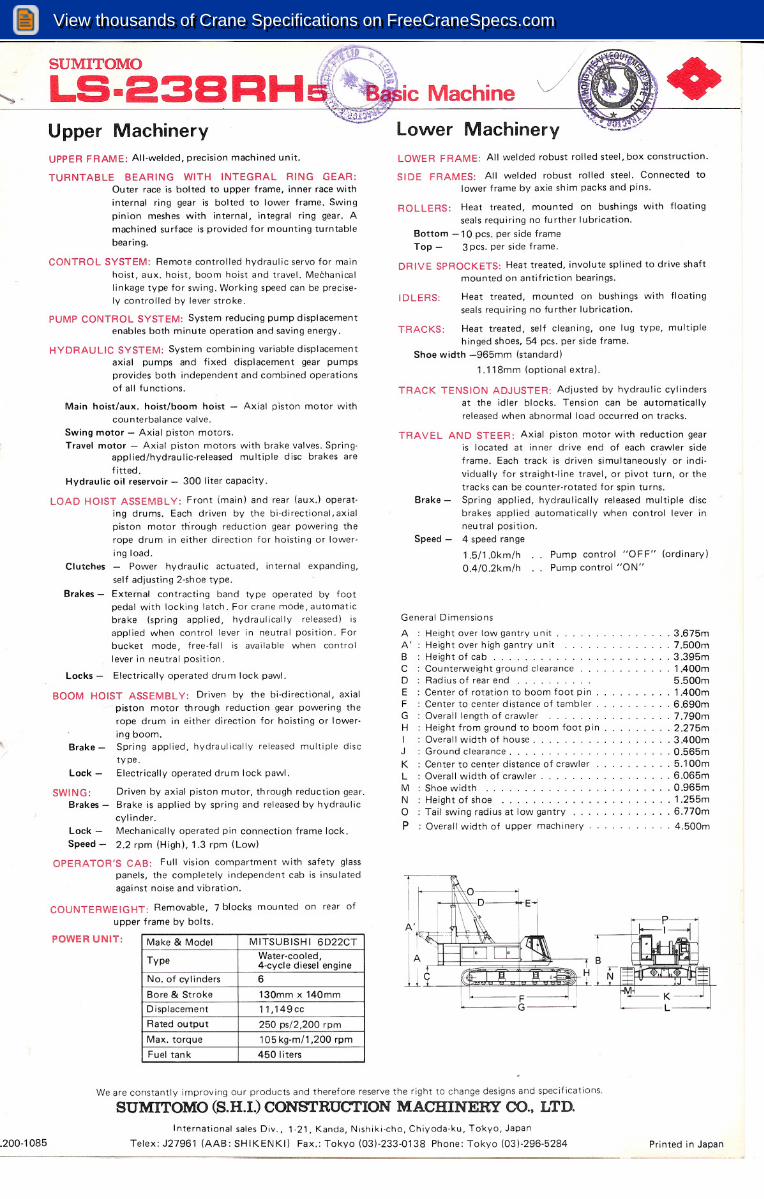
SUMITOMO
LS-23BUpper Machinery
Machine
lower Machinery
+UPPER FRAME: All-welded, precision machined unit.
HYDRAULIC SYSTEM: System combining variable displacementaxial pumps and fixed displacement gear pumpsprovides both independent and combined operationsof all functions.
TURNTABLE BEARING WITH INTEGRAL RING GEAR:Outer race is bolted to upper frame, inner race with
internal ring gear is bolted to lower frame. Swingpinion meshes with internal, integral ring gear. Amachined surface is provided for mounting turntablebearing.
CONTROL SYSTEM: Remote controlled hydraulic servo for mainhoist, aux. hoist, boom hoist and travel. Mechanicallinkage type for swing. Working speed can be precisely controlled by lever stroke.
PUMP CONTROL SYSTEM: System reducing pump displacementenables both minute operation and saving energy.
.3.675m· 7.500m· 3.395m· 1 AOOm
5.500m· lAOOm· 6.690m.7.790m.2.275m· 3AOOm. O.565m. 5.100m. 6.065m.O.965m.1.255m· 6.770m
· 4.500m
Pump control "OFF" (ordinary)Pump control "ON"
1.5/1 .Okm/hOA/0.2km/h
General Dimensions
A Height over low gantry unitA' Height over high gantry unitB He~htofcab .C Counterweight ground clearanceD Rad iu s of rear end .E Center of rotatio n to boom foot pinF Center to center distance of tamblerG Overall length of crawlerH Height from grou nd to boom foot pinI Overall width of house .J Ground clearance .K Center to center distance of crawlerL Overall width of crawlerM Shoe width .N Height of shoe .o Tail swing radius at low gantry
P : Overall width of upper machinery
IDLERS: Heat treated, mounted on bushings with floatingseals requiring no fu rther lubrication.
TRACKS: Heat treated, self cleaning, one lug type, multiplehinged shoes, 54 pes. per side frame.
Shoe width -965mm (standard)
1.118mm (optional extra).
TRACK TENSION ADJUSTER: Adjusted by hydraulic cylindersat the idler blocks. Tension can be automaticallyreleased when abnormal load occu rred on tracks.
TRA VEL AN D STE ER: Axial piston motor with reduction gearis located at inner drive end of each crawler side
frame. Each track is driven simultaneously or indiovidually for straight-line travel, or pivot turn, or thetracks can be counter-rotated for spin turns.
Brake - Spring applied, hydraulically released multiple discbrakes applied automatically when control lever inneutral position.
Speed - 4 speed range
ROLLERS: Heat treated, mounted on bushings with floatingseals requ i ri ng no fu rther Iubricati on.
Bottom -10 pes. per side frameTop - 3 pes. per side frame.
DRIVE SPROCKETS: Heat treated, involute splined to drive shaftmounted on antifriction bearings.
LOWER FRAME: All welded robust rolled steel, box construction.
SIDE FRAMES: All welded robust rolled steel. Connected tolower frame by axie shim packs and pins.
Driven by axial piston mutor, th rough reduction gear.Brake is applied by spring and released by hydraulic
cylinder.Mechanically operated pin connection frame lock.
2.2 rpm (High), 1.3 rpm (Low)
Lock
Speed -
SWING:Brakes -
Main hoist/aux. hoist/boom hoist - Axial piston motor withcounterbalance valve.
Swing motor - Axial piston motors.Travel motor - Axial piston motors with brake valves. Spring
applied/hydraulic-released multiple disc brakes arefitted.
Hydraulic oil reservoir - 300 liter capacity.
LOAD HOIST ASSEMBLY: Front imain) and rear (aux.) operat·ing drums. Each driven by the bi-directional, axialpiston motor tti rough reduction gear powering therope drum in either direction for hoisting or lowering load.
Clutches - Power hydraulic actuated, internal expanding,
self adjusting 2-shoe type.
Brakes - External contracting band type operated by footpedal with locking latch. For crane mode, automaticbrake (spring applied, hydraulically released) isapplied when control lever in neutral position. Forbucket mode, free-fall is available when controllever in neutral position.
Locks - Electrically operated drum lock pawl.
BOOM HOIST ASSEMBLY: Driven by the bi-directional, axialpiston motor through reduction gear powering therope drum in either direction for hoisting or lowering boom.
Brake - Spring applied, hydraulically released multiple disctype .
Lock - Electrically operated drum lock pawl .
OPERATOR'S CAB: Full vision compartment with safety glasspanels, the completely independent cab is insulatedagainst noise and vibration.
COUNTERWEIGHT: Removable, 7 blocks mounted on rear ofupper frame by bolts.
POWER UNIT: Make & Model MITSUBISHI 6D22CT
Type
Water·cooled,4-cycle diesel engineNo. of cylinders
6
Bore & Stroke
130mm x 140mm
Displacement
11,149cc
Rated output
250 ps/2,200 rpm
Max. torque
105 kg·m/1 ,200 rpm
Fuel tan k
450 liters
We are constantly improving our products and therefore reserve the right to change designs and specifications.
SUMITOMO (S.H.I.) CONSTRUCTION MACHINERY CO., LTD.
.200-1085International sales Div., 1-21, Kanda, Nishiki-cho, Chiyoda-ku, Tokyo, Japan
Telex: J27961 (AAB: SHIKENKI) Fax.: Tokyo (03)-233-0138 Phone: Tokyo (03)-296-5284 Printed in Japan
View thousands of Crane Specifications on FreeCraneSpecs.comView thousands of Crane Specifications on FreeCraneSpecs.com

SUMITOMO
LS-23BRHs ~Clamshell 2.0 - 3.0m3 +
CLAMSHELL BOOMS: Lattice construction; round tubular mainchords, alloy hi-ten steel, with bracing of round steeltubing.
Boom connections ... In-line pin connections.Basic boom ... Two-piece, 18.30m basic length; 7.62m base,
10.68m top section; 1.85 deep and 1.85m wide atconnections.
Boom point machinery ... Five head sheaves mounted onanti-friction bearings.
Boom extensions ... Available in 3.05m, 6.10m and 9.15mlengths with pendants.
GANTRY: Retractable high gantry
MAXIMUM CLAMSHELL RATING: 10.0t
LINE SPEED:
COUNTERWEIGHT: A (5.6t), B (4.6t), C (5.6t), D (9.3t), E (7.5t)F (0.8t), G (D.8t) Total ... 34.2t
SAFETY DEVICE: Boom over hoist limiting device, drum pawllock for closing, hold ing and boom hoist drum,swing lock, safety valve in hydraulic circuit, boomangle indicator, boom back stop.
TAG LINE WINDER: Spring-wound, drum-type mountpd onboom, double stage type StandardSpring-wound, drum-type mounted on boom, triplestage type Optional extraHydraulic type mounted in front of the revolvingframe Optional extra
GRADEABILlTY: 30% (170)with basic boom, 2.5m3 bucket and counterweightA,B,C,D,E,F,G.
Line speed (Closing, Holding)Drums
Root dia.TypePump controlPump controlCable dia.
"OFF" (Ordinary)
"ON"
Holding
546mmParallel groovedHigh 60 m/min
High 15 m/min26mmLow 30 m/minLow 7.5 m/min
Closing
546mmParallel groovedHigh 60 m/minHigh 15 m/min26mmLow 30 m/minLow 7.5 m/min
3rd drum320mmParallel grooved60 m/min15 m/min16mm
(Option)Boom hoist
420mmParallel grooved40 m/min10 m/min20mm
Hoisting line speed varies with load.
GANTRY: Retractable high gantry
WORKING WEIGHT AND GROUND PRESSURE:
Shoe widthWeightPressure
965mm
105.2t0.77 kg/cm2
With basic boom, 2.5 m3 bucket and counterweight A, B, C, D, E, F, G.Weight without counterweight and front attachment: approx. 60.5t
LS-238RH5 CLAMSHELL CAPACITIES AND WORKING RANGES:(in metric tons)
Boom Length (m)
18.30
21.3524.4027.45
R
ALRALRALRAL(m)
(0)(t)(m)(0 )(t)(m)(0 )(t)(m)(0 )(t)
9.0
67.710.0
10.0
64.210.010.068.110.0
12.0
56.910.012.062.210.012.065.910.0
14.0
48.910.014.055.810.014.060.610.014.064.210.0
16.0
39.710.016.048.910.016.055.010.016.059.410.0
18.0
41.210.018.048.910.018.054.310.0
20.0
42.210.020.048.910.0
22.0
43.010.0
R: Working radius A: Boom angle L: Rated load
Notes:1. Following weight of bucket plus load should not exceed above
rated loads.
Bucket capacity2.0m32.5m33.0m3
Bucket weight
4.5t5.5t6.5t
2. Boom length shall not exceed 21.35m.3. Apparent specific gravity of lifting material:
Earth 1.7- ~.8t/m3Gravel 1.8-2.0t/m3
4. High gantry is required for all operating conditions .
(in meters)
Bucket capacity2.0m32.5m33.0m3 *
A
Bucket overall height4.52
4.375.37(opened)
B
Bucket overall height3.69
3.464.36(closed)
C
Bucket opening width 3.243.653.65
D
Bucket clearance 7.47.47,4
• Light duty service
2-1085
We are constantly improving our products and therefore reserve the right to change designs and specifications.
SUMITOMO (S.H.I.) CONSTRUCTION MACHINERY CO., LTD.
International sales Div., 1 21, Kanda, Nishlkl-cho, Chiyoda-ku, To1<yo, Japan
Telex: J27961 (AAB: SHIKENKI) Fax.: Tokyo {D3)-233-0138 Phon~: Tokyo (03)-296·5284 Printed in Japan
View thousands of Crane Specifications on FreeCraneSpecs.comView thousands of Crane Specifications on FreeCraneSpecs.com

SUMITOMO
LS-23BRHs
~-
Working Boom length (m)radius (m)18.3021.3524.4027.4530.5033.5536.6039.6542.7045.7548.8051.8554.9057.9060.9564.0067.0570.1073.15
5.0
100.05.3
100.06.0
84.979.072.2
7.0
66.466.366.261.955.48.0
54.153.953.853.750.948.043.89.0
45.545.245.145.044.944.842.538.435.110.0
39.139.038.938.738.638.538.436.434.431.328.812.0
30.430.230.130.030.029.929.829.629.529.427.224.822.720.814.0
24.824.724.624.524.324.224.123.923.823.723.523.421.919.817.716.515.714.416.0
20.820.720.620.420.320.220.120.019.919.819.619.519.419.216.915.514.913.611.518.0
17.717.617.517.517.417.217.016.916.816.616.516.416.216.114.614.112.710.920.0
15.515.415.315.115.014.914.714.614.514.314.214.113.913.813.713.212.010.322.0
13.613.513.313.213.112.812.712.612.512.412.312.112.011.911.711.19.724.0
12.111.911.811.711.511.411.311.110.910.810.610.510.310.210.09.126.0
10.610.510.410.210.110.09.99.89.69.59.39.08.98.88.528.0
9.79.59.49.39.18.98.88.68.58.38.28.17.97.87.630.0
8.68.58.38.28.17.97.87.77.57.57.37.16.96.732.0
7.77.57.57.47.27.16.96.76.66.56.36.26.034.0
6.86.86.76.56.46.26.15.95.85.65.55.236.0
6.76.26.15.95.85.75.55.35.25.04.84.638.0
5.75.65.45.35.25.04.84.64.44.24.040.0
5.14.94.84.74.54.34.13.93.73.542.0
4.44.34.24.03.83.63.43.33.044.0
4.03.93.73.53.43.23.02.82.546.0
3.43.33.13.02.72.52.52.248.0
2.92.62.52.52.32.11.9
50.02.42.32.22.01.81.6
52.02.12.01.81.71.51.3
54.01.71.51.41.3
56.01.3
Notes:
1. Capacities shown are in metric tons and are based on 75% of
minimum tipping loads - over the side - with machine standinglevel on firm supporting surface under ideal job conditions.Deductions from the lifting crane capacities must be made forweight of hook block.
Kind of hook block (t) I 100503010
Weight of hook block (t) I 1.33
0.840.640040
2. When operating of the main boom peak sheaves with jib onboom the following deductions in machine lifting capacitiesmust be made.
Jib length 1m) 12.2018.3024.40
Weight to be deducted (t)
2.73.14.1
3. High gantry is required and side frames must be extended forall operating conditions.
LS-238RHs JIB CAPACITIES:(in metric tons)
Max. jibJib length (m)Jib set angleCapacities
10°
12.012.20 30°
8.0
10°
10.018.30 30°
6.0
10°
6.024.40 30°
4.S
" ),Ji b set angle
..•..•...•..•., ',,-
Ict
Boom working radiusJib working radius
Notes:1. The jib capacities are equal to the crane lifting capacities of
the main boom on which the jib is fixed except that they arerestricted by the maximum jib capacities shown left.
2. Jib working radius does not exceed the working radius of themain boom which fits the jib.
3. Deductions from the jib capacities must be made for weight ofjib hook block (OAGt).
4. Available boom length to attach the jib is from 39.65m to54.00m. The maximum jib length is 24.40m.
5. The jib set angle to boom must not exceed 30°
View thousands of Crane Specifications on FreeCraneSpecs.comView thousands of Crane Specifications on FreeCraneSpecs.com

Crane 100 metric tons
LS-238RH5 CRANE WORKING RANGESI /J
E
'tJc:"e
c.::J
'">o.cco
•...<:'"'iijJ:
I 111~~ 30°
70° 60°84 I~- 30°
~1J'"'!2:..
/-'"....•.//80/100
1 fj'!--.
76
~:..;/{/-, .............r--!..8.30
/ /f)J'lI-----...
~'1 ,,~6 II·'1073.15 ~-L..1Vd.
----f-- ---':::'~61172
r--....
I I//,1/~"--.•............-----... ""K "'"..........
~70.10 1/1»-.,V !i"-- -~I'""'-
68
I~---~ "-"-
6~ .05 //rr---
::::::::f-.-""
---........... '"
"'"~/!""-'"
64.~00' ~
@----r---
r-----:
::::-......•'/.'" '" '"
">64
/"" I'....
I............. ~~ '"
"'"""" "'-< '"- i"'--..'"i'--."'-
60.d5ir;Vr- ""
--- J'0 "'""""
"'-../"- "'-60 l- I~ ""'"x.""I II --/ I'--.. '"~
5?
.90 -t--- ;------... ---/ '""'-0- !'"'"56
-- "'-
I
.•.•.•.•~ I'--./"'- ~~ '"'"'"5j.9
o ~.•.•.•..
-----L ---f-.-..,'"~~ "'-"'-52i'-..
51.854'-_ I--....~ y"""-/'" "\t---
"-I'--.."-"-
I
1---..r--...~"'""'"v"'-
'"~48 f8.81O,.•.•.•..r----L .........../""-
""'"l' '""'-")/.•.......•.
"""
45.75--.,/--....~ /""~!"-'"'><
/''044
"-"""
I •.....
"-~ ~"">"'-y'"
4[.70
---h( ..•..•••...~"""
"> "-"-v '"'\40
"-"-
39.654~ --- ---I
""I'-.. "'"/'" "->(''\ \\
r-...I "-
-----...~ I"" "'-../"" "'-'\/\~\36
f---16.611 ----j--
..........."'-/ '>/''\ \r-....
"""-i"-..""'" \\33.55
1--- ___ /~/-. "',/"'- '"x~\\\.->:32 I ~"'";>r'\."'-X'\\\../7
I-- 30 i05;-------...
/"'" )"-"-t>('\ )../
28 P'15~ ~---/J'" >(\\>-.......•.
r'\.
I I/---I ~/"- /\ \\../24 f-rAi r ___1""/'" >
v '\\Y/'21.35
-.,""/'" ><~\v20
"- /'
18.130
/'A/"'- X~\.../
16
I'-/./"- >(\V/
/ """<-(//'
///'\/
12
/'
/ // \../
8
I / / /
,//// //''I/~'/r 1
ll~ "
48121620242832364044485256
1400l!)"'"'"
Working Radius 1m)
View thousands of Crane Specifications on FreeCraneSpecs.comView thousands of Crane Specifications on FreeCraneSpecs.com

CRANE BOOMS: Lattice construction; round tubular main chords, alloywith bracing of round steel tubing.Boom connections.Basic boom .
SUMITOMO
LS-23BRHs
Boom point machinery.
Boom extensions .....
Jib .
Jib extensions .
Boom plus jib length ...
HOOK BLOCK:
100t, five sheaves50t, two sheaves ..30t, one sheave .lOt, no sheave .
GANTRY: Retractable high gantry.
LINE SPEED:
Crane 100 metric tons
hi-ten steel,
In-line pin connections.Two-piece, 18.30m basic length; 7.62mbase, 10 .68m top section; 1.85m deepand 1.85 wide at connections.Five head sheaves mounted on antifriction bearings.Available in 3.05m, 6.10m and 9.15mlengths with pendants. Maximum boomlength 73.15m.Two-piece; 12.20m basic length with6.10m long base and top sections, 0.76mdeep and 0.91m Wide at connections.Available in 6.10m jib extensions. Maximum jib length 24.40m.57.90m + 24.40m.64.00m + 18.30m.
Standard.Optional extra.Optional extra.Standard for jib.
+)
rJ
Line speed (Hoisting, Lowering)DrumsRoot dia.TypePump controlPump controlCable dia.
"OFF" (Ordinary)"ON"
Main hoist546mmParallel grooved
High 60 m/minHigh 15 m/min26mm( Front) Low 30 m/minLow 7.5 m/min
Aux. hoist546mmParallel groovedHigh 60 m/minHigh 15m/min26mm(Rear) Low 30 m/minLow 7.5 m/min
Boom hoist420mmParallel grooved40 m/min10 m/min20mm
HOIST REEVING:
No pf parts of line
Max. load (1)
1
10.9
WORKING WEIGHT AND GROUND PRESSURE:
Shoe width WeightPressure965mm
101.2t0.74 kg/em'1 ,118mm (Opt)
106t0.77 kg/em'
With basic boom and counterweight.
COUNTERWEIGHT: A (5.6t), B (4.6t), C (5.6t), D (9.3t), E (7.5t), F (0.8t), G (0.8t)T ota I ... 34. 2 t
SAFETY DEVICE: Hook over hoist limiting device, boom over hoist limiting device, boom angle indicator,boom back stop, drum pawl lock for main, aux. and boom hoist drum, safety value inhydraulic circuit, swing lock, swing alarm, load moment limiter (optional extra~.
GRADEABILlTY: 30% (17°)
with basic boom and counterweight.
We are constantly improving our products and therefore reserve the right to change designs and specifications.
SUMITOMO (S.H.I.) CONSTRUCTION MACHINERY CO., LTD.
L201-1085International sales Div., 1·21. Kanda. Nishiki·cho, Chiyoda·ku, Tokyo, Japan
Telex: J27961 (AAB: SHIKENKI) Fax.: Tokyo (03)-233-0138 Phone: Tokyo (03)-296-5284 Printed in Japan
View thousands of Crane Specifications on FreeCraneSpecs.comView thousands of Crane Specifications on FreeCraneSpecs.com