Embed Size (px)
Citation preview
Summary and Analysis of Large Building Air Leakage
Testing for the U.S. Department of Defense.
J. Lee Durston, BCRA Building Science
Matthew Heron, PE, Pie Consulting and Engineering

Why Air Barriers and Why Now?
Energy Conservation Measure
First Costs/Construction
Operational Costs
Building Envelope Durability
H- Heat Barrier
A- Air Barrier
ML- Moisture Liquid
MV- Moisture Vapor
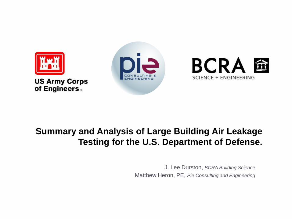
Energy
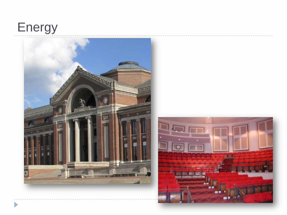
Durability
Benefits of an air-tightness standard:
Reduced building heating and cooling costs
Reduced building enclosure moisture problems
Improved indoor air quality
Improved acoustical isolation
Isolates the indoor environment
Sustainable, durable buildings
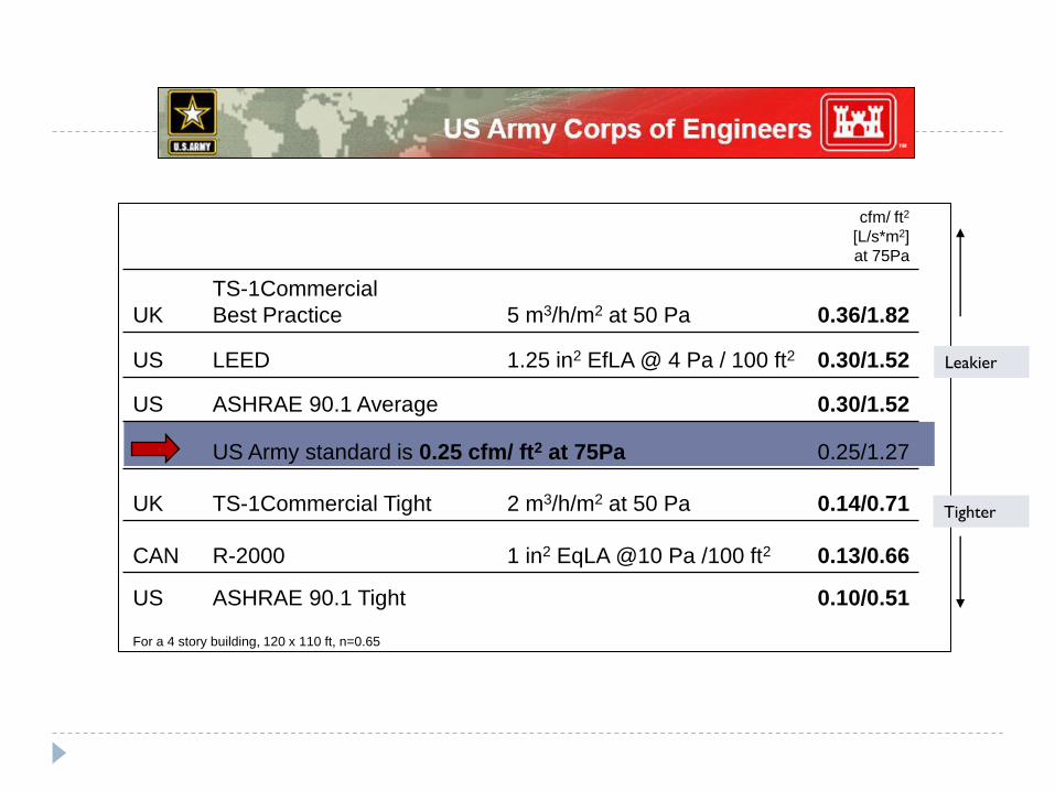
cfm/ ft2
[L/s*m2]
at 75Pa
UK
TS-1Commercial
Best Practice 5 m3/h/m2 at 50 Pa 0.36/1.82
US LEED 1.25 in2 EfLA @ 4 Pa / 100 ft2 0.30/1.52
US ASHRAE 90.1 Average 0.30/1.52
US Army standard is 0.25 cfm/ ft2 at 75Pa 0.25/1.27
UK TS-1Commercial Tight 2 m3/h/m2 at 50 Pa 0.14/0.71
CAN R-2000 1 in2 EqLA @10 Pa /100 ft2 0.13/0.66
US ASHRAE 90.1 Tight 0.10/0.51
For a 4 story building, 120 x 110 ft, n=0.65
Leakier
Tighter
Requirements for an Air Barrier System
1) It must be continuous, with all joints made tight.
2) The materials shall have an air permeability not to exceed 0.004
cfm/sf under a pressure differential of 0.3 in. of water. (Or 0.02
L/s/m2 @ 75 Pa)
3) It shall be capable of withstanding positive and negative combined
design, wind, fan and stack pressures on the envelope without
damage or displacement, and shall transfer the load to the structure.
It shall not displace adjacent materials under full load.

Requirements for an Air barrier System 4) It shall be durable or maintainable
5) The air barrier shall be joined in an airtight and flexible manner to the air barrier of adjacent systems, allowing for the relative movement of systems due to thermal and moisture variations and creep. Connections shall be made between: a) Foundations and walls
b) Walls and windows or doors
c) Different wall systems
d) Wall and roof
e) Walls, floor and roof across construction, control and
expansion joints
f) Walls, floor and roof and utility, pipe and
penetrations
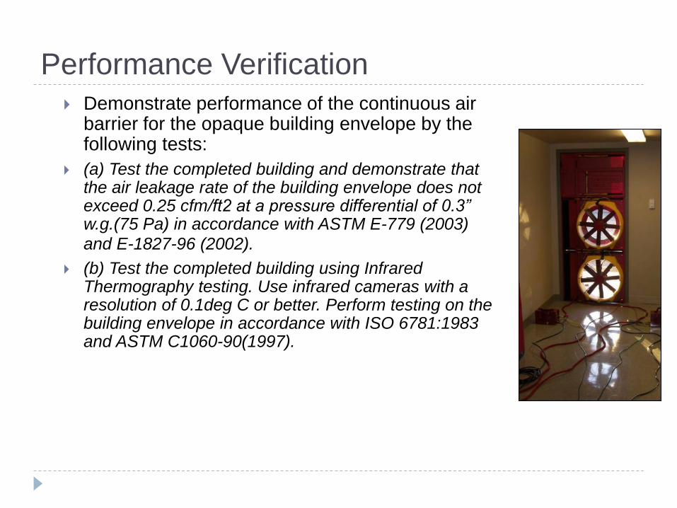
Performance Verification Demonstrate performance of the continuous air
barrier for the opaque building envelope by the following tests:
(a) Test the completed building and demonstrate that the air leakage rate of the building envelope does not exceed 0.25 cfm/ft2 at a pressure differential of 0.3” w.g.(75 Pa) in accordance with ASTM E-779 (2003)
and E-1827-96 (2002).
(b) Test the completed building using Infrared Thermography testing. Use infrared cameras with a resolution of 0.1deg C or better. Perform testing on the building envelope in accordance with ISO 6781:1983 and ASTM C1060-90(1997).

Assessment and Testing Protocol
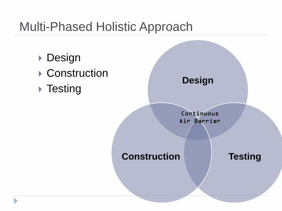
Multi-Phased Holistic Approach
Design
Construction
Testing Design
Testing Construction
Continuous
Air Barrier

What We Have Learned
CASE STUDIES

Case Study- Detroit Arsenal Bldg. 270
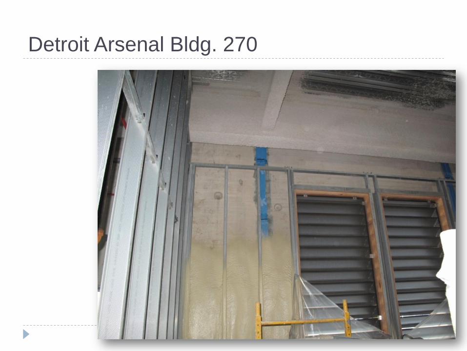
Detroit Arsenal Bldg. 270
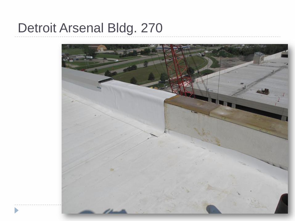
Detroit Arsenal Bldg. 270
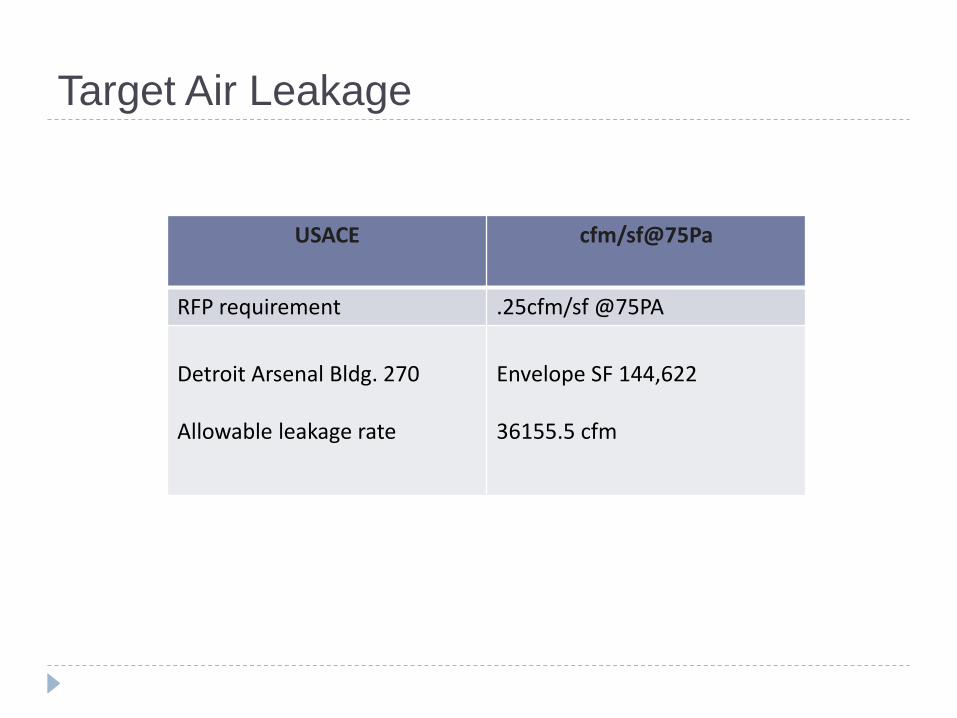
Target Air Leakage
USACE cfm/sf@75Pa
RFP requirement .25cfm/sf @75PA
Detroit Arsenal Bldg. 270 Allowable leakage rate
Envelope SF 144,622 36155.5 cfm
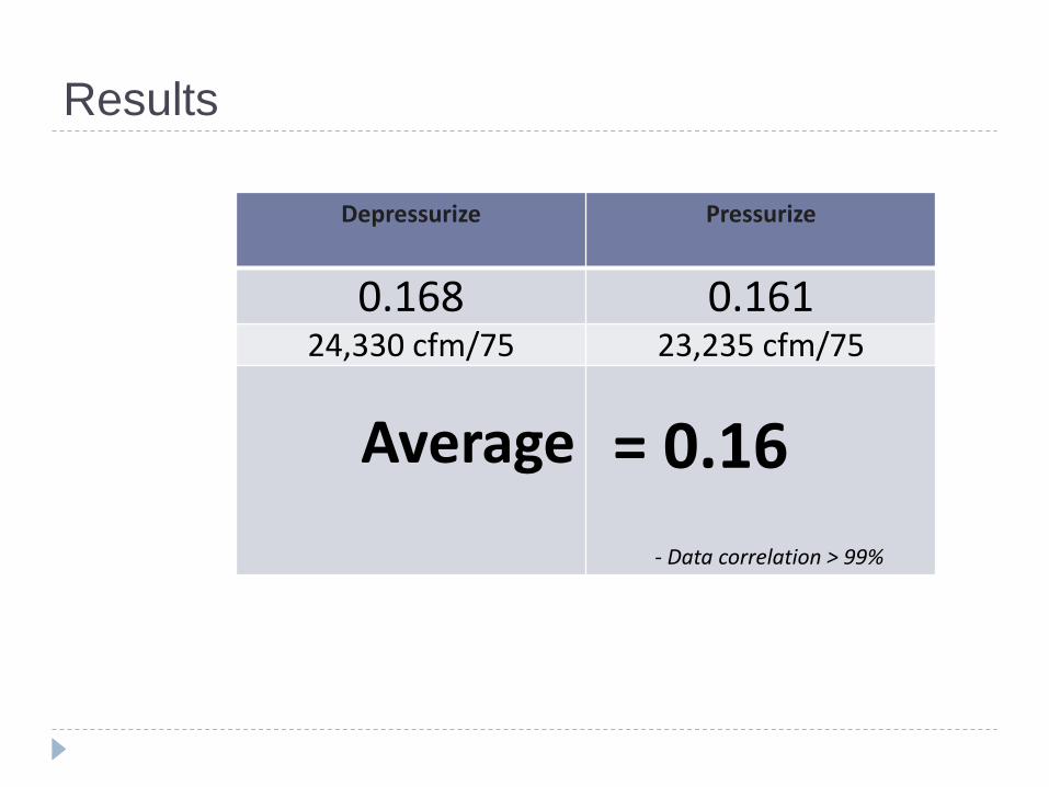
Results
Depressurize Pressurize
0.168 0.161 24,330 cfm/75 23,235 cfm/75
Average
= 0.16 - Data correlation > 99%
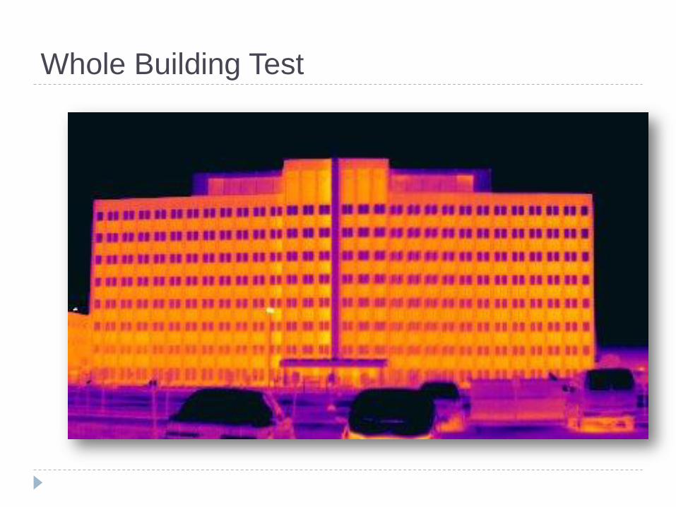
Whole Building Test
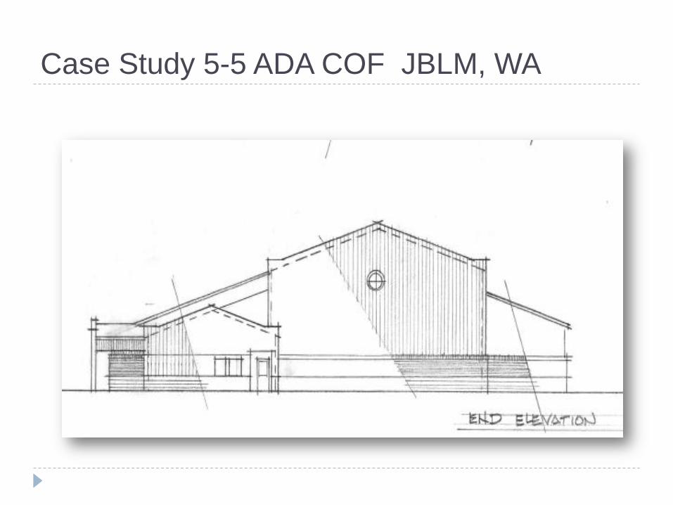
Case Study 5-5 ADA COF JBLM, WA
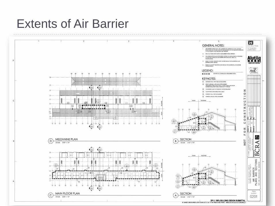
Extents of Air Barrier

Extents of Air Barrier
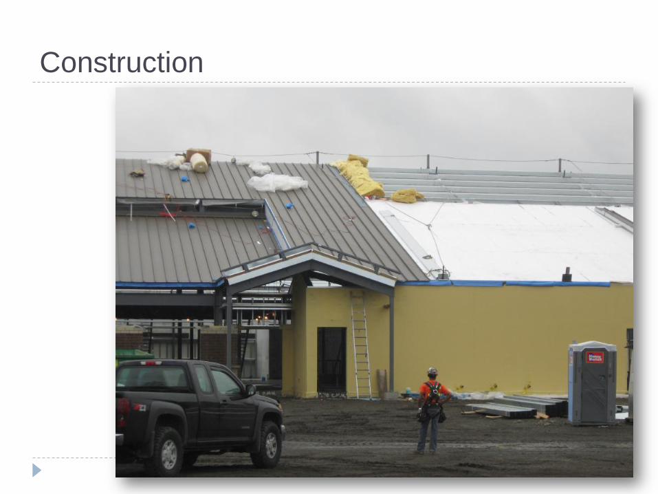
Construction
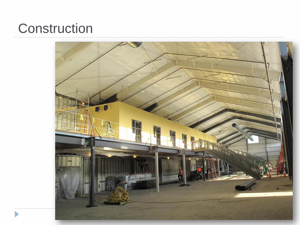
Construction
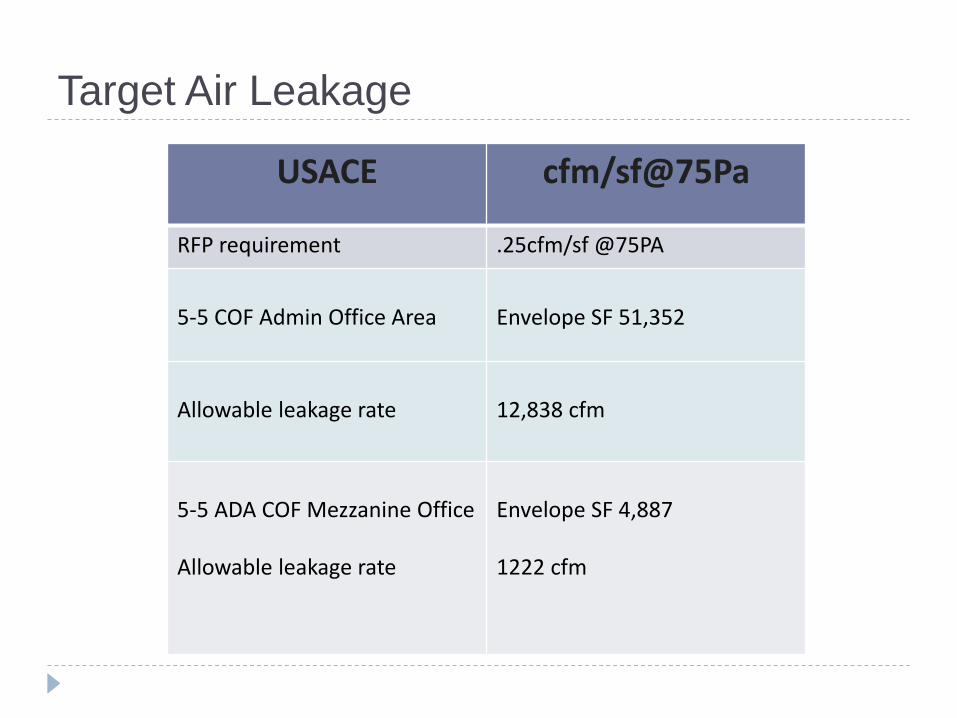
Target Air Leakage
USACE cfm/sf@75Pa
RFP requirement .25cfm/sf @75PA
5-5 COF Admin Office Area
Envelope SF 51,352
Allowable leakage rate
12,838 cfm
5-5 ADA COF Mezzanine Office Allowable leakage rate
Envelope SF 4,887 1222 cfm
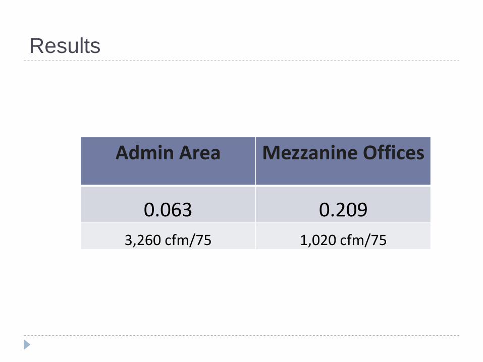
Results
Admin Area Mezzanine Offices
0.063 0.209
3,260 cfm/75 1,020 cfm/75
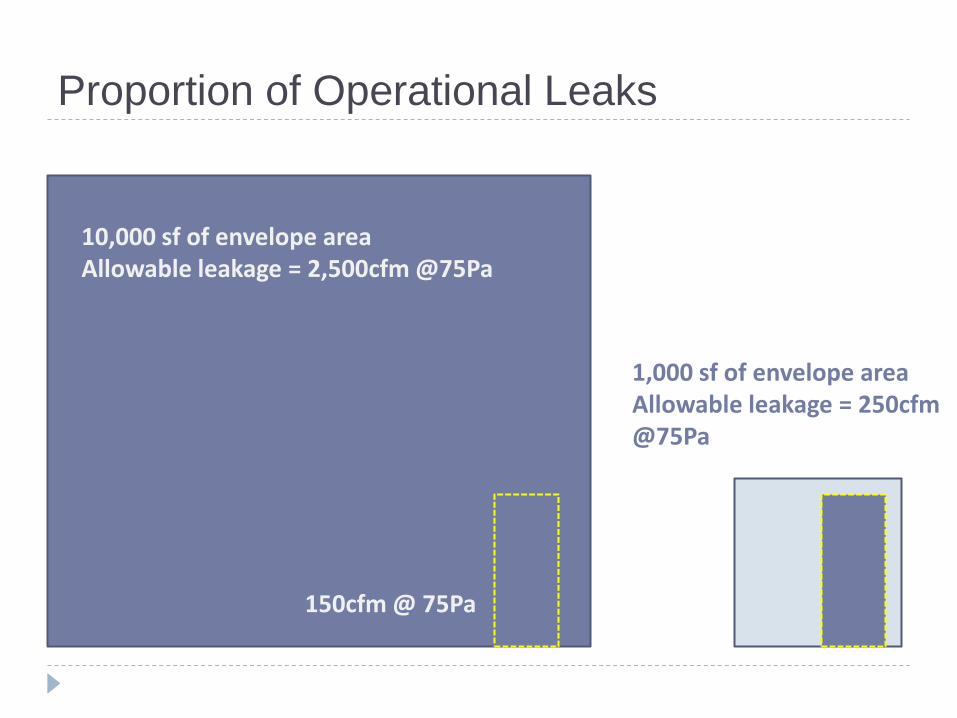
Proportion of Operational Leaks
10,000 sf of envelope area Allowable leakage = 2,500cfm @75Pa
150cfm @ 75Pa
1,000 sf of envelope area Allowable leakage = 250cfm @75Pa
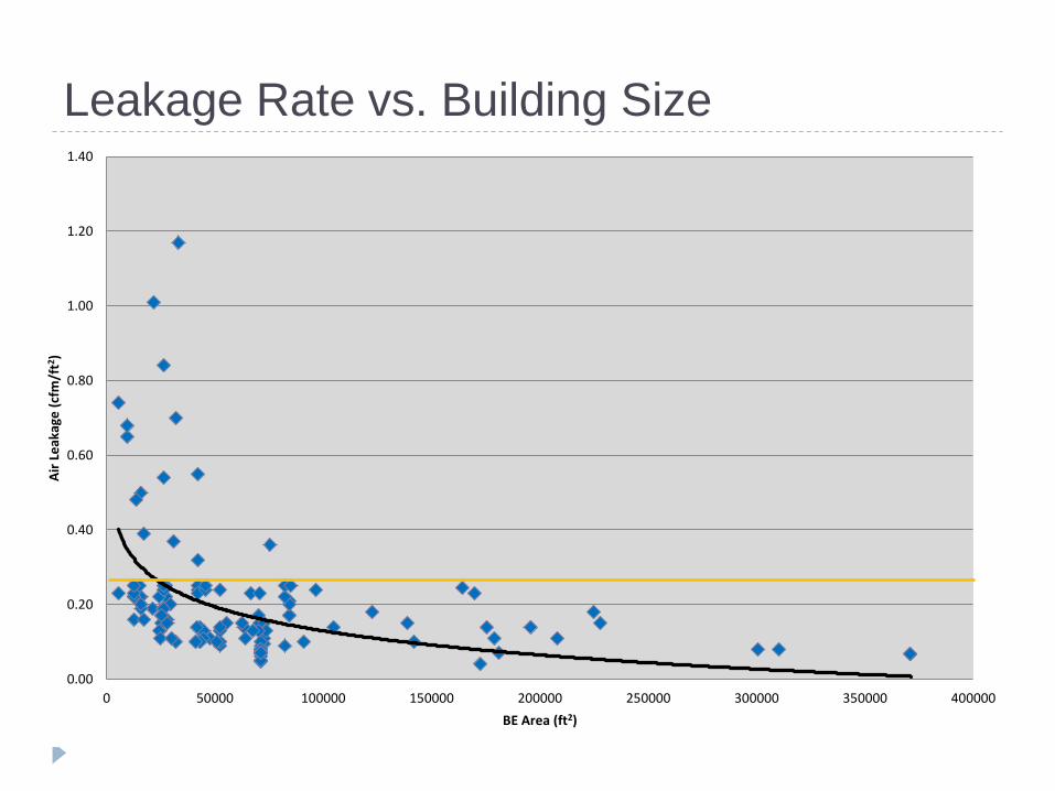
Leakage Rate vs. Building Size
0.00
0.20
0.40
0.60
0.80
1.00
1.20
1.40
0 50000 100000 150000 200000 250000 300000 350000 400000
Air
Le
akag
e (
cfm
/ft2
)
BE Area (ft2)
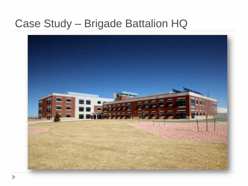
Case Study – Brigade Battalion HQ
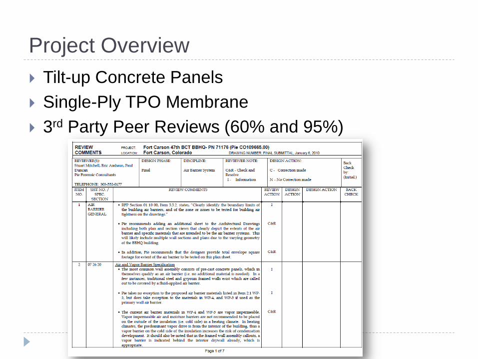
Project Overview
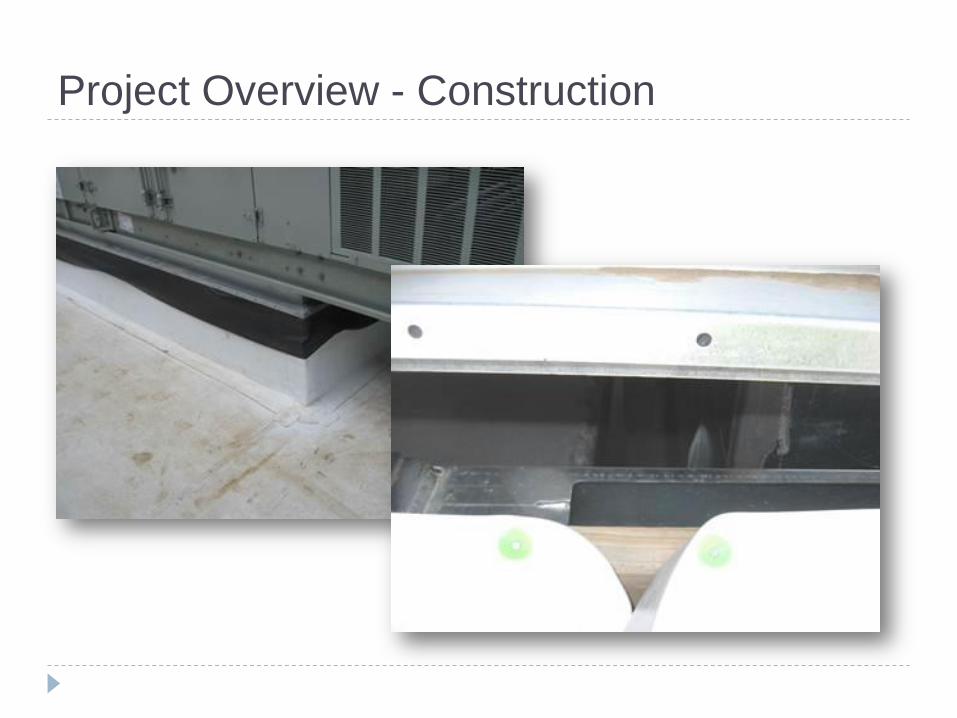
Tilt-up Concrete Panels
Single-Ply TPO Membrane
3rd Party Peer Reviews (60% and 95%)
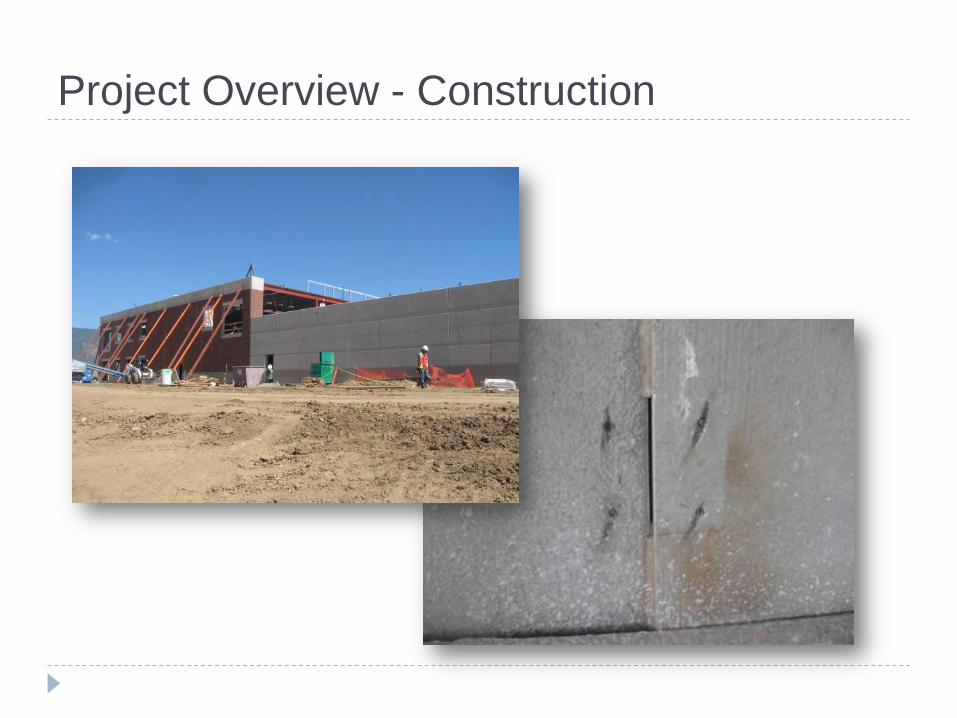
Project Overview - Construction

Project Overview - Construction
Project Overview - Construction
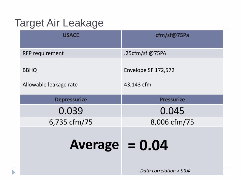
Target Air Leakage USACE cfm/sf@75Pa
RFP requirement .25cfm/sf @75PA
BBHQ Allowable leakage rate
Envelope SF 172,572 43,143 cfm
Depressurize Pressurize
0.039 0.045 6,735 cfm/75 8,006 cfm/75
Average
= 0.04 - Data correlation > 99%
lt
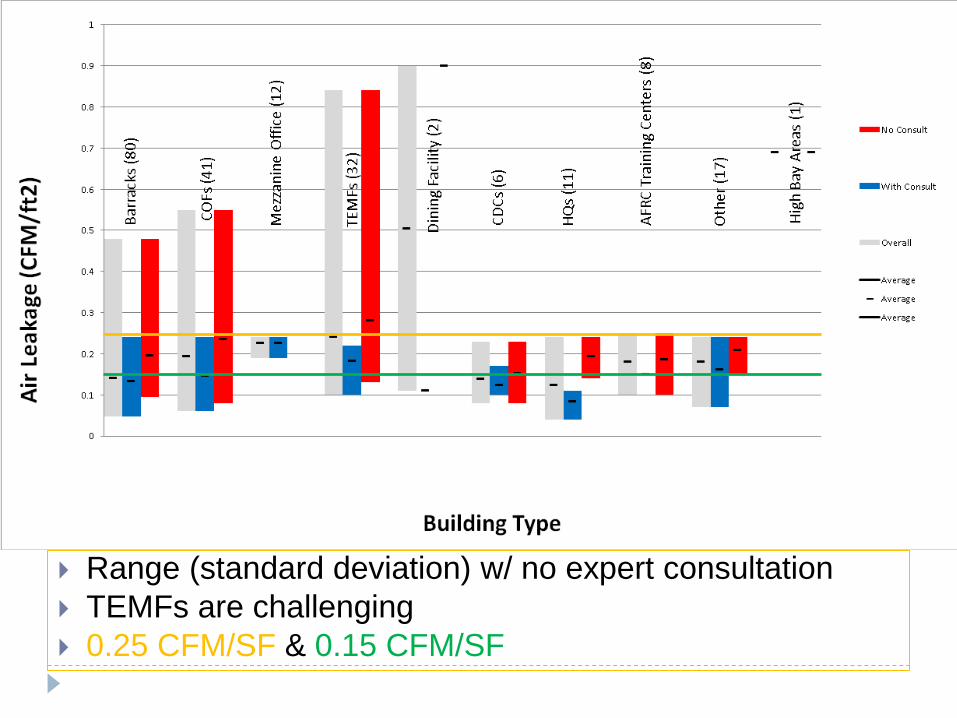
Range (standard deviation) w/ no expert consultation
TEMFs are challenging
0.25 CFM/SF & 0.15 CFM/SF
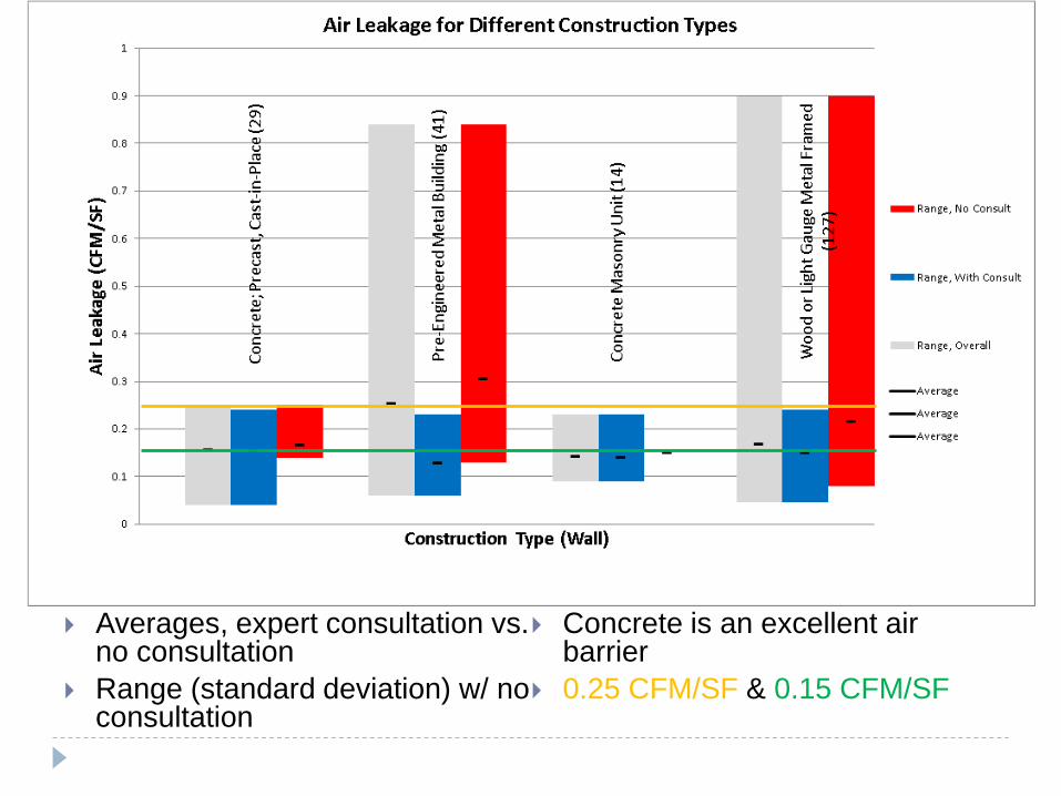
Averages, expert consultation vs. no consultation
Range (standard deviation) w/ no consultation
Concrete is an excellent air barrier
0.25 CFM/SF & 0.15 CFM/SF

Average & range, w/ no consultation 0.25 CFM/SF & 0.15 CFM/SF
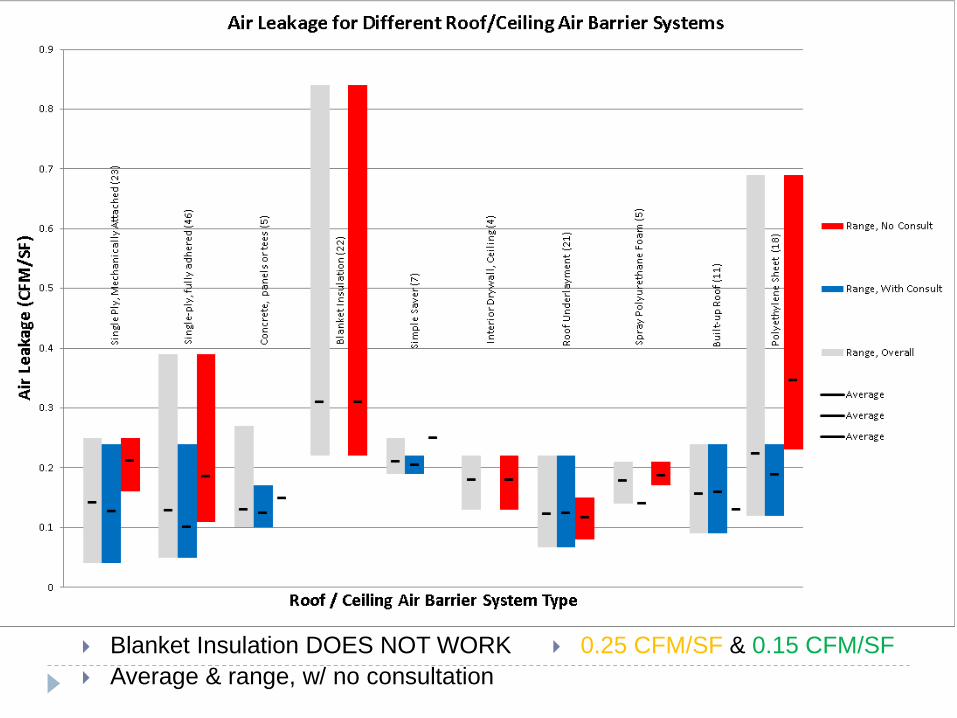
Blanket Insulation DOES NOT WORK
Average & range, w/ no consultation
0.25 CFM/SF & 0.15 CFM/SF
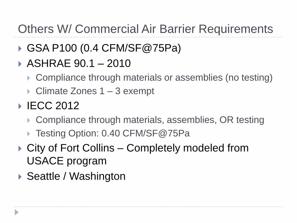
Others W/ Commercial Air Barrier Requirements
GSA P100 (0.4 CFM/SF@75Pa)
ASHRAE 90.1 – 2010
Compliance through materials or assemblies (no testing)
Climate Zones 1 – 3 exempt
IECC 2012
Compliance through materials, assemblies, OR testing
Testing Option: 0.40 CFM/SF@75Pa
City of Fort Collins – Completely modeled from
USACE program
Seattle / Washington
Question &
Answer Matt Heron, PE
Pie Consulting & Engineering
Lee Durston, BS, CBST
BCRA Building Science


![Practical Guide to Ductwork Leakage Testing. 5th Edition[1]](https://img.pdfslide.net/doc/110x75/5525b87d4a795993488b4cc6/practical-guide-to-ductwork-leakage-testing-5th-edition1.jpg)