Embed Size (px)
Citation preview

F6
1
Summary
Summary .................................................................................................................................. 1 F6 .............................................................................................................................................. 2 Technical Data .......................................................................................................................... 3 Belt type................................................................................................................................... 4 Standard modules ................................................................................................................... 5 How to write the order codes for motor drives ...................................................................11 Lateral guides ........................................................................................................................12 Lateral guides accessories.....................................................................................................17 Conveyor support systems ....................................................................................................21 How to write the order codes for conveyor support systems ............................................27 Conveyor support accessories ...............................................................................................28 Stainless steel F6 ...................................................................................................................34 How to write the order codes for stainless steel F6 module ..............................................35 How to use belt conveyors with end motor drive...............................................................36 How to use belt conveyors with central motor drive .........................................................38

F6
2
F6 is a belt conveyor conceived with modular design for light load
Suitable for the transportation of light product and with small dimensions, has a maximum work load of 30 Kg*. Its speed can reach 60 m/min* in function of the installed motor gear and the conveyor dimensions.
F6 is a belt conveyor system, suitable for food industry and not, ideal for the transportation of products with small dimensions. F6 is an Italian product that can offer flexible solutions to a wide range of needs in the product handling process. F6 was designed to be easy to use, both by plant and machine builders and by companies that need to handle products. F6 is a practical system, that allows to use a vast range of accessories and standard components available on the market. F6 interfaces easily with other systems and allows to reuse different elements of related components.

F6
3
Technical Data*
Product dimensions: 20÷400 mm The geometric shape of the product to be handled influences the maximum width of products accommodated by the system.
Maximum weight on the conveyor: 35 Kg The maximum weight on the conveyor is limited to the need to reduce at minimum the belt wear and the stress on the tow roller
Maximum conveyor length: 6 m The maximum length of the conveyor depends on the total load, the motor drive capacity, the speed and the conveyor layout. It is important to calculate and compare the maximum belt tension and the motor drive capacity in the following situations: - Heavy loads - Accumulation - High speed - Long conveyor - Frequency of starts and stops
Belt conveyor layout: Conveyor layout fundamentally depends on the type of motorization installed: - BELT CONVEYOR WITH FLANGED END MOTOR DRIVE (TEF45): Lx2 + 43 mm - BELT CONVEYOR WITH CENTRAL MOTOR DRIVE (TCP4545 e TCP4512): Lx2 + 285 mm (where L is the conveyor length)
Maximum conveyor speed: 60÷70 m/min The maximum speed of the conveyor depends on the total load and the motor drive capacity.
Noise level of the conveyor: The composition and the materials used for the realization of the belt conveyor, makes them the quietest type of conveyor.
* The data indicated above should be considered indicative of normal conveyor performance. For applications that have values outside of this range or have particular working conditions, please contact our technical office for a feasibility assessment.

F6
4
Belt type MH supplies 6 different standard models of belt for some main brand in the sector: Habasit, Siegling, Ammeral, Chiorino, Mabelt. Determining factors in the choice of the belt are: - conveyor model on which it will be installed - the type of application that the conveyor belt will have to carry out - The environment in which the conveyor belt will work - Possible specifications for the brand or other requests from the client If the client requires theme, different brand, materials and accessories are available for every belt. For further information and evaluation on the best belt type for your needs, please contact our Technical Department.
Typical Applications
CHOCOLATE
TINS, CANS, AND JARS
BAKERY PRODUCTS
MECHANCAL ELEMENTS
AND ELECTRICAL PARTS
CHEESES
PRODUCTS IN PLASTIC
BLISTER PACKS
TCP4545 and TEF45 belts
N1 Rough belt with low fiction with 2 canvas, suitable for accumulation of carton or plastic boxes
N2 2 canvas smooth spreaded with good surface endurance and maximum thickness, low friction for small accumulation, suitable for low slope and the transportation of metal particulars
N3 2 canvas with crossed relief surface for high speed phase conveyors or honeycombed, suitable for high slope, unsuitable for accumulation TCP4512 belts
N4 Rough belt with low fiction with 2 canvas, suitable for accumulation of carton or plastic boxes
N5 2 canvas smooth spreaded with low friction for small accumulation, suitable for low slope
N6 Good fiction to overcome slow scope, unsuitable for accumulation

F6
5
Standard modules
Flanged end motor drive (TEF45) Belt conveyor with left/right flanged end motor drive with idle return roller Ø 45 mm
Technical specifications: Standard motor : Triphase 220/380 V
Standard speed at 50 Hz (m/min)
: 4.8, 9.6, 12.5, 19, 27.5
Width : 20 mm÷400 mm
Length : 2000 mm max
Max Load : 20 Kg
W = Belt width A = Volume depending to the motor gear type
L = Conveyor length

F6
6
Article
NumberDescription Article Code
1 BELT
2 SLIDING PLAN **
3 RETURN END Ø 45 mm PLATE P12514
4 RETURN ROLLER Ø 45 mm **
5 TENSIONING BLOCK P12515
6 RETURN ROLLER SHAFT **
7 PS4040 ALUMINUM FRAME R5696
8 FRLANGED END DRIVE PLATE P12548
9 BEARING INSIDE FLANGE 2205-2RS
10 DRIVE ROLLER Ø 45 mm **
11 BEARING 6002-2RS
12 END DRIVE PLATE P12549C
* Depends on the motor type ** Depends on conveyor dimensions
NOTE: For conveyors longer than 2 meters, it will need to add some rollers on the return track to avoid excessive belt lanyards.

F6
7
Central suspended motor drive (TCP4545) Central left/right suspended motor drive with idle return rollers Ø 45 mm. The central motor drive can be installed at any point along the conveyor. and is directly connected to the belt drive roller.
Technical specifications: Standard motor : Triphase 220/380 V
Standard speed at 50 Hz (m/min)
: 4, 12.5, 19.5, 35, 50
Width : 60 mm÷400 mm
Length : 6000 mm max
Max Load : 35 Kg
W = Belt width A = Volume depending to the motor gear type
L = Conveyor length

F6
8
Article
NumberDescription Article Code
1 BELT
2 TENSIONING BLOCK P12515
3 RETURN ROLLER Ø 45 mm P12514
4 PS4040 ALUMINUM FRAME R5696
5 CENTRAL DRIVE PLATE P125719
6 CENTRAL DRIVE PROTECTION P12520
7 DRIVE SUPPORT UFL-005
8 REACTION ARM PIN F5TM06
9 REACTION LEVER *
10 DRIVE SHAFT PROTECTION
11 DRIVE SHAFT *
12 DRIVE ROLLER **
13 RETURN ROLLER Ø 45 mm **
14 BEARING 6002-2RS
15 RETURN ROLLER SHAFT **
16 SLIDING PLAN **
* Depends on the motor type ** Depends on conveyor dimensions
NOTE: For conveyors longer than 2 meters, it will need to add some rollers on the return track to avoid excessive belt lanyards.

F6
9
Central suspended motor drive (TCP4512) Centrale left/right suspended motor drive with idle return roller Ø 45 mm and pen Ø 12 mm. The central motor drive can be installed at any point along the conveyor. and is directly connected to the belt drive roller
Technical specifications: Standard motor : Triphase 220/380 V
Standard speed at 50 Hz (m/min)
: 4, 9.5, 12.5, 19.5, 25
Width : 20 mm÷400 mm
Length : 2500 mm max
Max Load : 35 Kg
W = Belt width A = Volume depending to the motor gear type
L = Conveyor length

F6
10
Article
NumberDescription Article Code
1 BELT
2 SLIDING PLAN **
3 IGUS BUSH JSM 1012 20
4 RETURN PEN Ø 12 mm
5 RETURN PEN PLATE P12516 SX
P12516 DX6 TENSIONING BLOCK P12515
7 CENTRAL DRIVE PLATE P125719
8 CENTRAL DRIVE PROTECTION P12520
9 DRIVE SUPPORT UFL-005
10 REACTION ARM PIN F5TM06
11 DRIVE SHAFT PROTECTION
12 REACTION LEVER *
13 DRIVE SHAFT *
14 DRIVE ROLLER **
15 RETURN ROLLER Ø 45 mm **
16 BEARING 6002-2RS
17 RETURN ROLLER SHAFT **
18 RETURN ROLLER Ø 45 mm PLATE P12514
19 PS4040 ALUMINUM FRAME R5696
* Depends on the motor type ** Depends on conveyor dimensions
NOTE: For conveyors longer than 2 meters, it will need to add some rollers on the return track to avoid excessive belt lanyards.

F6
11
HOW TO WRITE THE ORDER CODES FOR MOTOR DRIVES
Description Order Code
Motor drive type
Flanged suspended end Central suspend end with Ø 45 mm rollers Central suspend end with Ø 12 mm pen
: F6 TEF : F6 TCP 4545 : F6 TCP 4512
Drive side
Right: D
Left: S
Belt width W (width in mm)
Blet length L (length in mm)
Motor gear type
Bonfiglioli MVF49 Bonfiglioli W63
SEW WA20 SEW WA30
Motor gear presence Yes: Y No: N
Belt type Low friction rough belt Spreaded belt for low slopes Belt for phase conveyors or high slopes
: N1 o N4 : N2 o N5 : N3 o N6
If purchasing the drive unit with your order, please specify the required speed at the time of ordering.
Example:
Right suspended central motor drive with Ø 45 mm rollers and SEW WA30 motor gear included and belt for high slopes 200 mm wide and 2000 mm long
Cod: F6TCP4545-D-W200-L2000-WA30-N3
NOTE: For speeds above 20 m/min or in the presence of frequent starts or high loads, it is essential to put the motors under soft starter or inverter

F6
12
Lateral guides F6 is an open system that allows to use several types of supports and lateral guides found on the market. The guides shown below can be either fixed or adjustable, depending on client needs. The corresponding data are correlated to a basic guide format: on request, accessories to increase flexibility are available. For more technical information and evaluations, please contact our Technical Office.
Fixed guides
F6 GPF1
Composition (per channel meter): Clearance:
GL40P GL30A DS2010A6/16/26 PSG95
: 2 m : 2 m : 4 pieces : 4 pieces
X Y
: L-3 mm minimum* : 3 ÷ 28 mm*
(where L is the width of the belt)
* The X dimension changes with the length of the aluminum spacer. The Y dimension varies through the slot in the PSG95 plate.

F6
13
F6 GPF3
Composition (per channel meter): Clearance:
GL12SS MGT12 DS2010A27/37/47 PSG95
: 2 m : 4 pieces : 4 pieces : 4 pieces
X Y
: L+47 mm minimum* : 15 ÷ 48 mm*
(where L is the width of the belt)
* The X dimension changes with the length of the aluminum spacer. The Y dimension varies through the slot in the PSG95 plate.
__________________________________________________________________
F6 GPF4
Composition (per channel meter): Clearance:
GL16PA DS2010A6/16/26 PSG10
: 2 m : 4 pieces : 4 pieces
X Y
: L+4 mm minimum* : 3 ÷25 mm*
(where L is the width of the belt)
* The X dimension changes with the length of the aluminum spacer. The Y dimension varies through the slot in the PSG10 plate.

F6
14
F6 GPF6
Composition (per channel meter): Clearance:
GL31SS MGL31SS DS2010A18/28/38 PSG95
: 2 m : 4 pieces : 4 pieces : 4 pieces
X Y
: L+30 mm minimum* : 3 ÷32 mm*
(where L is the width of the belt)
* The X dimension changes with the length of the aluminum spacer. The Y dimension varies through the slot in the PSG95 plate.

F6
15
Guide regolabili
F6 GPR4
Composition (per channel meter): Clearance:
GL40P GL30A SG11 DS11 PFG14
: 2 m : 2 m : 4 pieces : 4/8/12 pieces : 4 pieces
X Y
L+110 ÷ 30 mm minimum* : 21 ÷ 43 mm*
(where L is the width of the belt)
* The X dimension depends on the number of DS11 spacers used and the adjustment provided by the PFG14 pin. The Y dimension is Y varies through the slot in the SG11 support and on the DS11 spacer.
__________________________________________________________________
F6 GPR11
Composition (per channel meter): Clearance:
GL12SS MGT12 SG11 SG11DS11 PFG14
: 2 m : 4 pieces : 4 pieces : 4/8/12 pieces : 4 pieces
X Y
: L+160 ÷ 20 mm minimum* : 41 ÷ 63 mm*
(where L is the width of the belt)
* The X dimension depends on the number of DS11 spacers used and the adjustment provided by the PFG14 pin. The Y dimension is Y varies through the slot in the SG11 support and on the DS11 spacer.

F6
16
F6 GPR17
Composition (per channel meter): Clearance:
GL31SS MGL31SS SG11 DS11 PFG14
: 2 m : 4 pieces : 4 pieces : 4/8/12 pieces : 4 pieces
X Y
: L+136 ÷ 4 mm minimum* : 26 ÷ 48 mm*
(where L is the width of the belt)
* The X dimension depends on the number of DS11 spacers used and the adjustment provided by the PFG14 pin. The Y dimension is Y varies through the slot in the SG11 support and on the DS11 spacer.

F6
17
Lateral guides accessories
Support
Material : Polyamide
Colour : Black
Packaging : 10 pieces
Order Code: SG11
Guide fastening pin
Material : Stainless steel
Packaging : 10 pieces
Order Code: PFG14
Support spacer
Material : Polyamide
Colour : Black
Packaging : 10 pieces
Order Code: DS11
__________________________________________________________________
Material : Anodized aluminum
Packaging : Custom cut into bars
Order Code: DS2010A

F6
18
Guide support clamps
Material : Polyamide
Colour : Black
Packaging : 10 pieces
Order Code: MGT12
__________________________________________________________________
Material : Polyamide
Colour : Black
Packaging : 20 pieces with bolts
Order Code: MGL31SS
__________________________________________________________________
Material : Stainless steel
Packaging : 10 pieces
Order Code: PSG95
__________________________________________________________________
Material : Polyamide
Colour : Black
Packaging : 10 pieces
Order Code: PSG10

F6
19
Profiles
Material : Polyethylene
Colour : Green
Length : 3 m
Order Code: GL40P
__________________________________________________________________
Material : Anodized aluminum
Length : 6 m
Order Code: GL30A
__________________________________________________________________
Material : Stainless steel and Polyamide
Colour : White
Length : 3 m
Order Code: GL31SS
__________________________________________________________________
Material : Stainless steel
Length : 3/6 m
Order Code: GL12SS

F6
20
Material : Anodized aluminum and Polyamide
Colour : White
Length : 3 m
Order Code: GL16A
Intermediate guide (GLP40) clamps
Material : Polyamide
Colour : Black
Packaging : 10 pieces with screws
Order Code: MBPI
Guide (GLP40) clamp for curves
Material : Polyamide
Colour : Black
Packaging : 10 pieces with screws
Order Code: MBPC
Terminal guide (GLP40) clamp
Material : Polyamide
Colour : Black
Packaging : 10 pieces with screws
Order Code: MBPT
F6
21
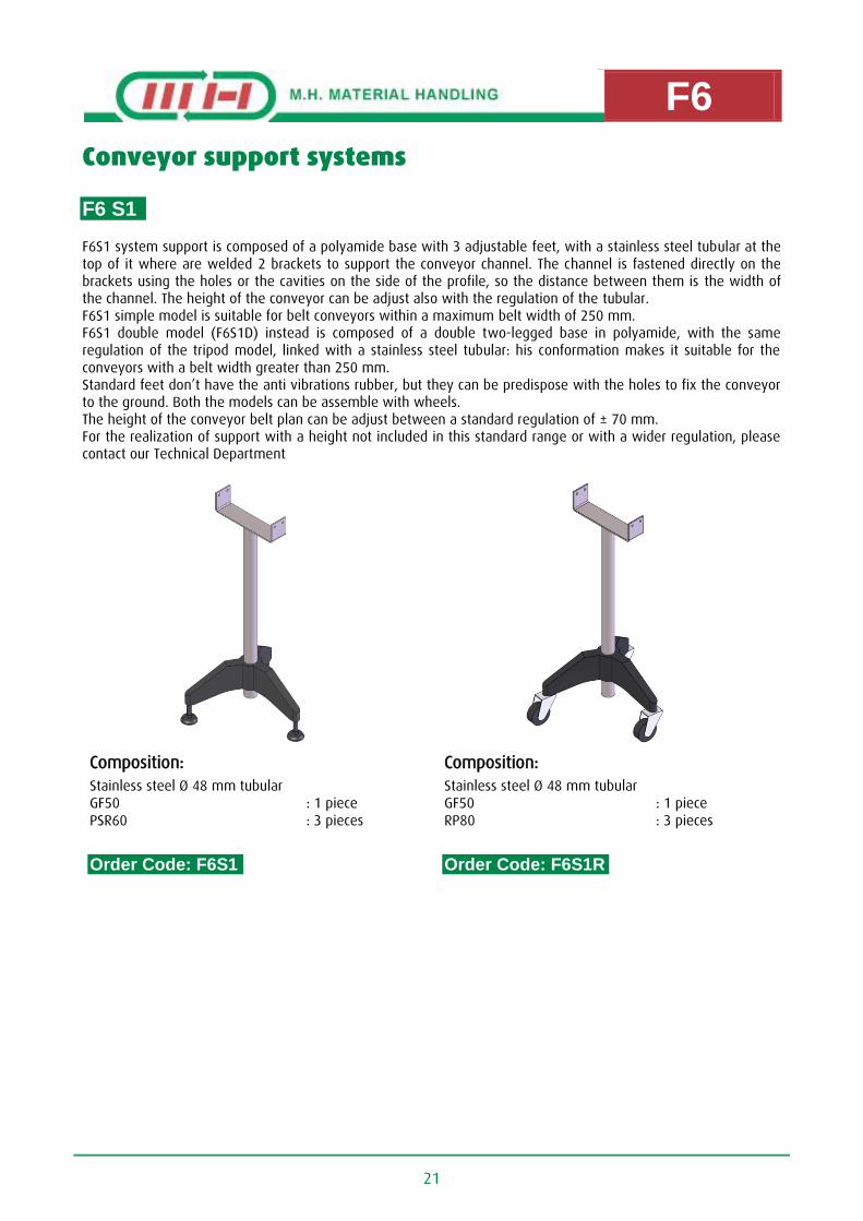
Conveyor support systems
F6 S1 F6S1 system support is composed of a polyamide base with 3 adjustable feet, with a stainless steel tubular at the top of it where are welded 2 brackets to support the conveyor channel. The channel is fastened directly on the brackets using the holes or the cavities on the side of the profile, so the distance between them is the width of the channel. The height of the conveyor can be adjust also with the regulation of the tubular. F6S1 simple model is suitable for belt conveyors within a maximum belt width of 250 mm. F6S1 double model (F6S1D) instead is composed of a double two-legged base in polyamide, with the same regulation of the tripod model, linked with a stainless steel tubular: his conformation makes it suitable for the conveyors with a belt width greater than 250 mm. Standard feet don’t have the anti vibrations rubber, but they can be predispose with the holes to fix the conveyor to the ground. Both the models can be assemble with wheels. The height of the conveyor belt plan can be adjust between a standard regulation of ± 70 mm. For the realization of support with a height not included in this standard range or with a wider regulation, please contact our Technical Department
Composition: Composition:
Stainless steel Ø 48 mm tubular GF50 PSR60
: 1 piece : 3 pieces
Stainless steel Ø 48 mm tubular GF50 RP80
: 1 piece : 3 pieces
Order Code: F6S1 Order Code: F6S1R
F6
22
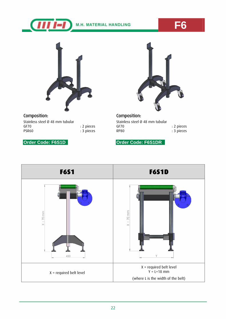
Composition: Composition:
Stainless steel Ø 48 mm tubular GF70 PSR60
: 2 pieces : 3 pieces
Stainless steel Ø 48 mm tubular GF70 RP80
: 2 pieces : 3 pieces
Order Code: F6S1D Order Code: F6S1DR
F6S1 F6S1D
X = required belt level
X = required belt level Y = L+18 mm
(where L is the width of the belt)

F6
23
F6S2D – F6S5D F6S2D and F6S5D systems support are composed of a two-legged frame built with a painted iron or stainless steel square tubular of two different dimensions: - 40x40 mm for F6S2D system - 50x50 mm for F6S5D system
The feet at the base of the frame are in polyamide and are adjustable in height, with a maximum of ± 50 mm. The 2 brackets for the support of the conveyor channel are welded directly on the frame. The channel is fastened on the brackets using the holes on the side of the profile, so the distance between the brackets is the width of the channel. Both the models are suitable for every belt conveyor, independently of the width of the belt used: the frame will be custom built with the necessary size. Standard feet don’t have the anti vibrations rubber, but they can be predispose with the holes to fix the conveyor to the ground. Both the models can be assemble with wheels. For the realization of support with a height not included in this standard range or with a wider regulation, please contact our Technical Department
Composition: Composition:
Square tubular frame 40x40 mm PSR100
: 2 pieces
Square tubular frame 40x40 mm RP80
: 2 pieces
Order Code: F6S2D Order Code: F6S2DR

F6
24
Composition: Composition:
Square tubular frame 50x50 mm PSR100
: 2 pieces
Square tubular frame 50x50 mm RP80
: 2 pieces
Order Code: F6S5D Order Code: F6S5DR
F6S2D F6S5D
X = required belt level Y = L+208 mm Z = L+150 mm
(where L is the width of the belt)
X = required belt level Y = L+198 mm Z = L+150 mm
(where L is the width of the belt)

F6
25
F6S3 F6S3 system support is composed of two-legged frame built with a anodized aluminum profile of different dimensions: - 40x40 mm and 80x40 mm for F6S3 system - Only 40x40 mm for F6S3D system
The feet at the base of the frame are in polyamide and are adjustable in height, with a maximum of ± 50 mm. The 2 brackets for the support of the conveyor channel are screwed directly on the frame, using the cavities on the profile. The channel is fastened on the brackets using the holes on the side of the profile, so the distance between the brackets is the width of the channel. Every model is suitable for different belt conveyors, depending on the width of the chain that is used:
F6S3 simple model is suitable for belt conveyors within a maximum belt width of 250 mm F6S3D model is suitable for belt conveyors with a belt width greater than 250 mm Standard feet don’t have the anti vibrations rubber, but they can be predispose with the holes to fix the conveyor to the ground. Both the models can be assemble with wheels. For the realization of support with a height not included in this standard range or with a wider regulation, please contact our Technical Department
Composition: Composition:
Frame in aluminum profile SFC20 BPSA4040 PS4040 PS8040 PSR100
: 2 pieces : 2 pieces : 1 piece : 2 pieces : 2 pieces
Frame in aluminum profile SFC20 BPSA4040 PS4040 PS8040 RP80
: 2 pieces : 2 pieces : 1 piece : 2 pieces : 2 pieces
Order Code: F6S3 Order Code: F6S3R

F6
26
Composition: Composition:
Frame in aluminum profile 40x40 mm SFC20 BPSA4040 PS4040 PSR100
: 2 pieces : 2 pieces : 3 pieces : 2 pieces
Frame in aluminum profile 40x40 mm SFC20 BPSA4040 PS4040 RP80
: 2 pieces : 2 pieces : 3 pieces : 2 pieces
Order Code: F6S3D Order Code: F6S3DR
F6S3 F6S3D
X = required belt level
X = required belt level Y = L+74 mm
(where L is the width of the belt)

F6
27
HOW TO WRITE THE ORDER CODES FOR CONVEYOR SUPPORT SYSTEMS
Description Order Code
Support type
F6S1 F6S1R F6S1D F6S1DR F6S2D F6S2DR F6S3 F6S3R F6S3D F6S3DR F6S5D F6S5DR
Material (if available)
Stainless Steel: X
Belt width W (width in mm)
Belt plan height H followed from the height measure of the belt plan in mm
Example:
F6S5D support in stainless steel height 915 mm for a belt 200 mm wide Cod: F6S5D-X-W200-H915

F6
28
Conveyor support accessories
Support base with feet
Material : Reinforced polyamide
Colour : Black
Packaging : 8 pieces
Order Code: GF50
__________________________________________________________________
Material : Reinforced polyamide
Colour : Black
Packaging : 8 pieces
Order Code: GF70
Channel fastening bracket
Material : Sanded aluminum
Packaging : 10 Pieces
Order Code: SFC20

F6
29
Support feet
Material : Galvanized steel and Polyamide
Colour : Black
Packaging : 10 pieces
Order Code: PSR100
__________________________________________________________________
Material : Galvanized steel and Polyamide
Colour : Black
Packaging : 10 pieces
Order Code: PSR60
__________________________________________________________________
Material : Galvanized steel and rubber
Packaging : 1 piece
Order Code: RP80

F6
30
Sanded aluminum bases
Material : Sanded aluminum
Packaging : 10 Pieces
Order Code: BPSA4040
__________________________________________________________________
Material : Sanded aluminum
Packaging : 10 Pieces
Order Code: BPSA8040
__________________________________________________________________
Material : Sanded aluminum
Packaging : 10 Pieces
Order Code: BPSA8080
Support profiles
Material : Anodized aluminum
Length : 3÷6 meters in bars
Order Code: PS4040
__________________________________________________________________
Material : Anodized aluminum
Length : 3÷6 meters in bars
Order Code: PS8040

F6
31
Profile cap
Material : Polyamide
Colour : Black
Packaging : 10 pieces
Order Code: TC4040
Square nuts
Material
: Galvanized steel
Stainless steel
Packaging : 100 pieces
Order Code: DRM4/5/6/8
Connecting angles
Material : Sanded aluminum
Packaging : 10 Pieces
Order Code: AC3525
__________________________________________________________________
Material : Sanded aluminum
Packaging : 10 Pieces
Order Code: AC3525C

F6
32
Material : Sanded aluminum
Packaging : 10 Pieces
Order Code: AC3570
__________________________________________________________________
Material : Anodized aluminum
Packaging : 10 Pieces
Order Code: AC3070
__________________________________________________________________
Material : Sanded aluminum
Packaging : 10 Pieces
Order Code: AC4387

F6
33
Profile joining plate
Material : Sanded aluminum
Packaging : 10 Pieces
Order Code: PG4040
__________________________________________________________________
Material : Sanded aluminum
Packaging : 10 Pieces
Order Code: PG8040
__________________________________________________________________
Material : Galvanized steel
Packaging : 10 Pieces
Order Code: PG630/45/60/90

F6
34
Stainless steel F6 For lines in which the conveyor touches the naked product or where it is necessary that the conveyor channel not have slots or for specific requests, a version of F6 TCP4545 made in stainless steel is available.
Technical specifications: Standard motor : Triphase 220/380 V
Standard speed at 50 Hz (m/min)
: 4, 12.5, 19.5, 35, 50
Width : 60 mm÷400 mm
Length : 6000 mm max
Max Load : 35 Kg
W = Belt width A = Volume depending to the motor gear type
L = Conveyor length

F6
35
HOW TO WRITE THE ORDER CODES FOR STAINLESS STEEL F6 MODULE
Description Order Code
Motor drive type Stainless steel central suspend end : F6 TCPX 4545
Drive side
Right: D
Left: S
Belt width W (width in mm)
Blet length L (length in mm)
Motor gear type
Bonfiglioli MVF49 Bonfiglioli W63
SEW WA20 SEW WA30
Motor gear presence Yes: Y No: N
Belt type Low friction rough belt Spreaded belt for low slopes Belt for phase conveyors or high slopes
: N1 o N4 : N2 o N5 : N3 o N6
If purchasing the drive unit with your order, please specify the required speed at the time of ordering.
Example:
Right suspended central motor drive with Ø 45 mm rollers and SEW WA30 motor gear included and belt for high slopes 200 mm wide and 2000 mm long
Cod: F6TCPX4545-D-W200-L2000-WA30-N3

F6
36
How to use belt conveyors with end motor drive
1. Prior to start-up the system verify correspondence between motor data and electrical power supply data.
2. Verify that no foreign objects are inside the conveyor
3. At the start-up the conveyor should not travel in a different direction than the one it has been designed for. Verify travelling movement of belt which should run centred onto the drums. It is suggested to do so because the system could have been damaged during transport which could take to lateral drifts causing unthreading of the belt.
4. Limits load to what foreseen by constructor.
How to centring the belt
To assure a correct function on any belt conveyor it is very important to verify that the drums are perpendicular to the side beam.
Start-up the unloaded conveyor. Tension the side where the belt is drifting to by acting on the adjustable plates as shown in picture.
Necessary tools : 1. Socket head screwdriver n°4 2. Socket head screwdriver n°3 3. Hexagon wrench n°10
Loose the nuts (With the Allen key 3) and slowly adjust until the belt is perfectly centred
Keep the conveyor running and verify that the belt maintains a centred positions on the driving drum.
Once centred the belt repeat the same procedure on both idler drums
Tensioning regulators

F6
37
How to replace the belt
1. Unloose completely the tension registers.
2. Take off the old belt and change it with the new one.
3. Reassemble all the components following the previous points in the opposite manner.
4. Tension and centre the belt following the instructions in the previous page.
Necessary tools : 1. Socket head screwdriver n°4

F6
38
How to use belt conveyors with central motor drive
1. Prior to start-up the system verify correspondance between motor datas and electrical power supply datas.
2. Verify that no foreign objects are inside the conveyor
3. At the start-up the conveyor should not travel in a different direction than the one it has been designed for. Verify travelling movement of belt which should run centered onto the drums. It is suggested to do so because the system could have been damaged during transport which could take to lateral drifts causing unthreading of the belt.
4. Limits load to what foreseen by constructor.
How to centring the belt
To assure a correct function on any belt conveyor it is very important to verify that the drums are perpendicular to the side beam.
Start-up the unloaded conveyor. Tension the side where the belt is drifting to by acting on the adjustable plates as shown in picture.
Necessary tools : 1. Socket head screwdriver n°4 2. Socket head screwdriver n°3 3. Hexagon wrench n°10 4. Cross screwdriver
Using the cross screwdriver remove the safety guard on the central drive unit.
Loose the nuts “A” and slowly adjust until the belt is perfectly centered moving the grub screw “B” as shown in the picture 2.
Keep the conveyor running and verify that the belt maintains a centered positions on the driving drum.
Once centered the belt repeat the same procedure on both idler drums.
Loose nuts “C” and slowly adjust until the belt is perfectly centered moving the grub screw “D” as shown in the picture 2.
Keep the conveyor running and verify that the belt maintains a centered positions on the drums. Then tighten nut “C”.
Reassemble the safety guard on the drive unit.

F6
39
How to replace the belt
1. Remove safety guard under the drive unit.. (Picture 1) 2. Unloose completely the tension registers (Pictures 2.1 + 2.2) 3. Unloose completely the holding screws of the drive unit’s frame opposite to the gearbox side. (Picture 3) 4. Allentare completamente le viti di fissaggio testata al canale dal lato opposto al motore. (Picture 4) 5. Take out the frame and the tension rollers. Be carefully at the rollers fall. (Picture 5) 6. Take off the old belt and change it with the new one. 7. Riassemble all the components following the previous points in the opposite manner. 8. Riassemble all the components following the previous points in the opposite manner.
Foto 1
Foto 1
Picture 2.1 Picture 2.2
Picture 1

F6
40
Foto 2
Picture 4
Picture 3

F6
41
Picture 5