Embed Size (px)
Citation preview
1
Appendix 4: Summary of Installed FRP Decks and Their Damage Inspection
1.0 INTRODUCTION
FRP composite structures for use as vehicular bridge decks have successfully transitioned from the experimental to commercial stage over the past decade. Close to 100 deck installations in the US alone have thus far been cataloged by the Market Development Alliance (MDA)1 organization. The inventory of FRP deck placed in service clearly shows that a small group of manufacturer/suppliers have been successful at bringing FRP bridge decks to commercial viability. Manufacturing efficiency generally dictates the repeatable production of a standard design. Thus, despite the growing number of installed FRP decks, the actual number of unique deck designs can be reduced to the field of manufacturer/supplier sources (less than two dozen at present) and the number of deck types each has to offer. For this reason it is reasonable to discuss the deck designs according to manufacturer/supplier, cross referenced by deck installation projects and subsequent variety of deck types the manufacturer/supplier offers. Any unique aspects of the designs impacting inspection techniques will be discussed within each section.
1.1 Scope
This section will concentrate on the FRP deck designs that are or have been manufactured and placed into service over the past decade in the US. A list of established FRP deck manufacturers to date has been generated.
As mentioned, the discussion will cover mainly in-service decks within the US. The specific discussion of manufacturing issues, anomalies, and in-service problems is based on filed reports and undocumented conversations with the various owners and the manufacturers that have taken place to date.
1.2 FRP Deck Manufacturer list
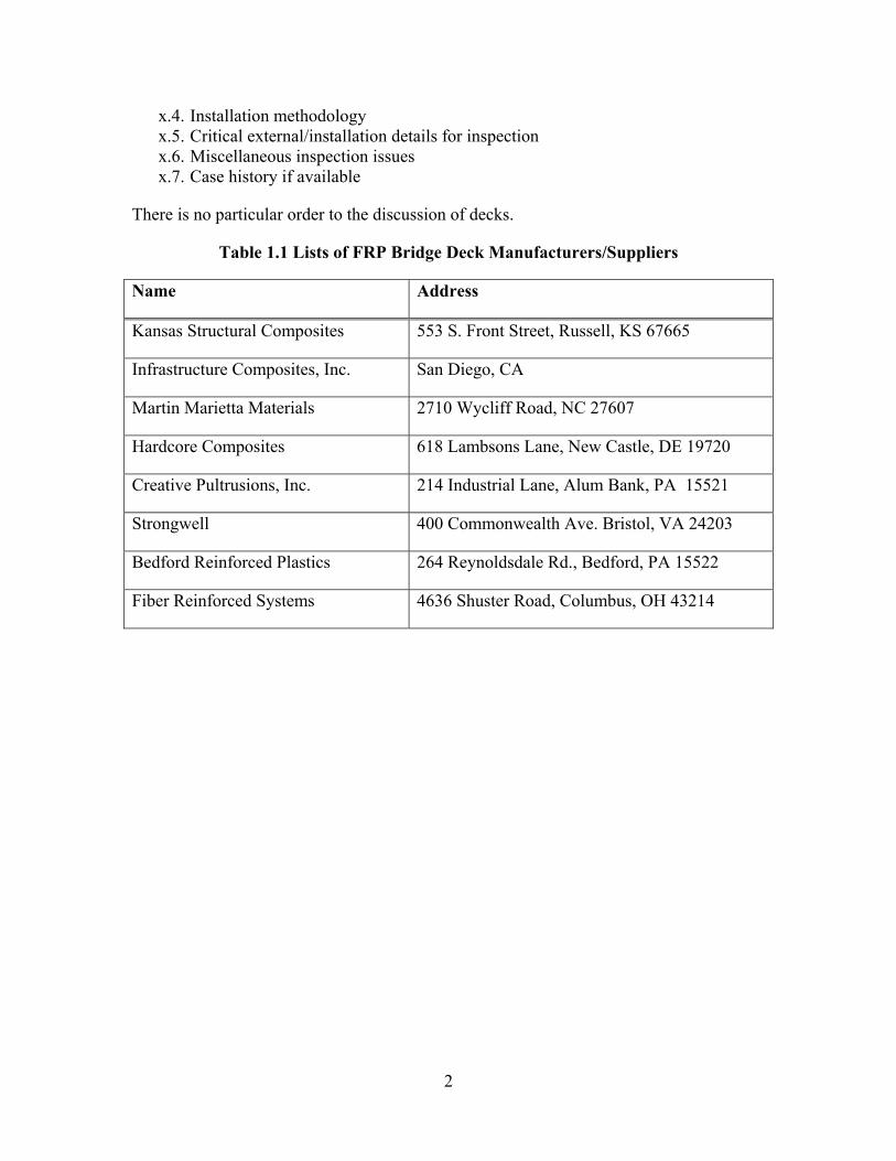
The current list of industry manufacturers/suppliers of FRP composite bridge decks that have completed one or more public installation projects (versus non-vehicular, private and university research) is given in Table-1.1 To the best of the research team members’ knowledge, they are all direct market suppliers of FRP decks and deck systems and are generally contacted directly for assistance.
1.3 Discussion Outline
The flow of discussion for each deck type will be as follows:
x.1. Manufacturer and brief background x.2. Description of deck x.3. Critical geometry details for inspection
1 For listing of infrastructure projects using FRP materials, refer to the web site: http://www.mdacomposites.org
2
x.4. Installation methodology x.5. Critical external/installation details for inspection x.6. Miscellaneous inspection issues x.7. Case history if available
There is no particular order to the discussion of decks.
Table 1.1 Lists of FRP Bridge Deck Manufacturers/Suppliers
Name Address
Kansas Structural Composites 553 S. Front Street, Russell, KS 67665
Infrastructure Composites, Inc. San Diego, CA
Martin Marietta Materials 2710 Wycliff Road, NC 27607
Hardcore Composites 618 Lambsons Lane, New Castle, DE 19720
Creative Pultrusions, Inc. 214 Industrial Lane, Alum Bank, PA 15521
Strongwell 400 Commonwealth Ave. Bristol, VA 24203
Bedford Reinforced Plastics 264 Reynoldsdale Rd., Bedford, PA 15522
Fiber Reinforced Systems 4636 Shuster Road, Columbus, OH 43214
3
2.0 KANSAS STRUCTURAL COMPOSITES, INC., RUSSELL, KS
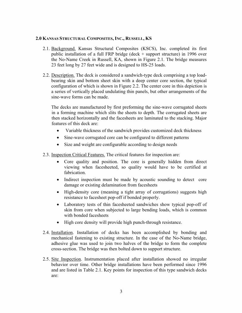
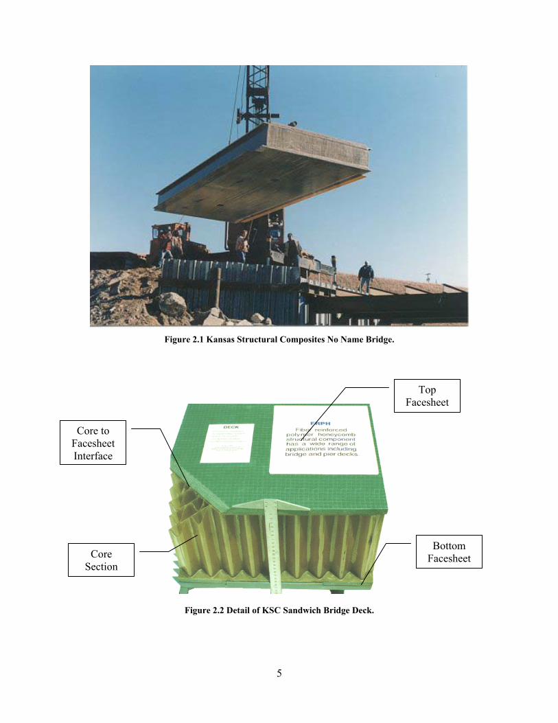
2.1. Background. Kansas Structural Composites (KSCS), Inc. completed its first public installation of a full FRP bridge (deck + support structure) in 1996 over the No-Name Creek in Russell, KA, shown in Figure 2.1. The bridge measures 23 feet long by 27 feet wide and is designed to HS-25 loads.
2.2. Description. The deck is considered a sandwich-type deck comprising a top load-bearing skin and bottom sheet skin with a deep center core section, the typical configuration of which is shown in Figure 2.2. The center core in this depiction is a series of vertically placed undulating thin panels, but other arrangements of the sine-wave forms can be made.
The decks are manufactured by first preforming the sine-wave corrugated sheets in a forming machine which slits the sheets to depth. The corrugated sheets are then stacked horizontally and the facesheets are laminated to the stacking. Major features of this deck are:
• Variable thickness of the sandwich provides customized deck thickness • Sine-wave corrugated core can be configured to different patterns • Size and weight are configurable according to design needs
2.3. Inspection Critical Features. The critical features for inspection are: • Core quality and position. The core is generally hidden from direct
viewing when facesheeted, so quality would have to be certified at fabrication.
• Indirect inspection must be made by acoustic sounding to detect core damage or existing delamination from facesheets
• High-density core (meaning a tight array of corrugations) suggests high resistance to facesheet pop-off if bonded properly.
• Laboratory tests of thin facesheeted sandwiches show typical pop-off of skin from core when subjected to large bending loads, which is common with bonded facesheets
• High core density will provide high punch-through resistance.
2.4. Installation. Installation of decks has been accomplished by bonding and mechanical fastening to existing structure. In the case of the No-Name bridge, adhesive glue was used to join two halves of the bridge to form the complete cross-section. The bridge was then bolted down to support structure.
2.5. Site Inspection. Instrumentation placed after installation showed no irregular behavior over time. Other bridge installations have been performed since 1996 and are listed in Table 2.1. Key points for inspection of this type sandwich decks are:
4
• The mechanical connections and visible bondlines across existing joint. • Any bump or rise in the flat surface which might signal debonding of the top
facesheet to core corrugation. • Signs of water leaks on exit ports indicating water accumulation in interior
cavities.
2.6. Other Inspection Issues. See Section 3
2.7. Case History.
Interviews with KSC and various owners of installed decks are in progress and will be reported when completed
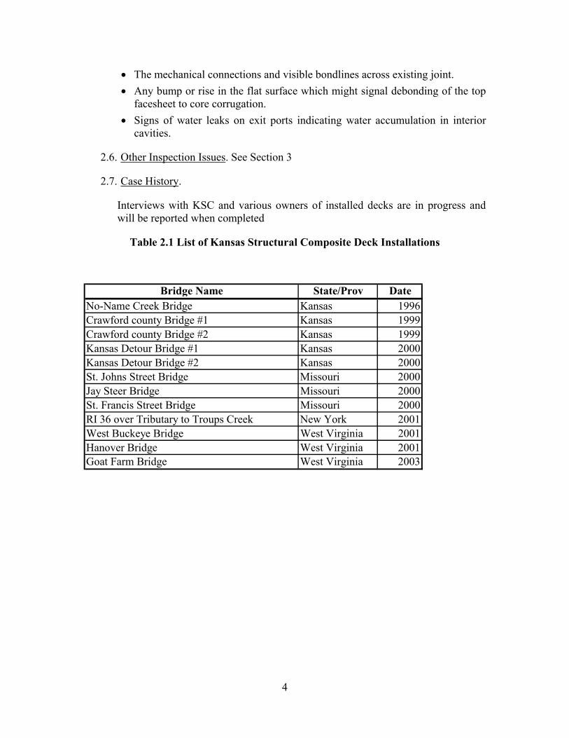
Table 2.1 List of Kansas Structural Composite Deck Installations
Bridge Name State/Prov DateNo-Name Creek Bridge Kansas 1996Crawford county Bridge #1 Kansas 1999Crawford county Bridge #2 Kansas 1999Kansas Detour Bridge #1 Kansas 2000Kansas Detour Bridge #2 Kansas 2000St. Johns Street Bridge Missouri 2000Jay Steer Bridge Missouri 2000St. Francis Street Bridge Missouri 2000RI 36 over Tributary to Troups Creek New York 2001West Buckeye Bridge West Virginia 2001Hanover Bridge West Virginia 2001Goat Farm Bridge West Virginia 2003
5
Figure 2.1 Kansas Structural Composites No Name Bridge.
Figure 2.2 Detail of KSC Sandwich Bridge Deck.
Top Facesheet
Core to Facesheet Interface
Core Section
Bottom Facesheet
6
3.0 INFRASTRUCTURE COMPOSITES, INC., CA
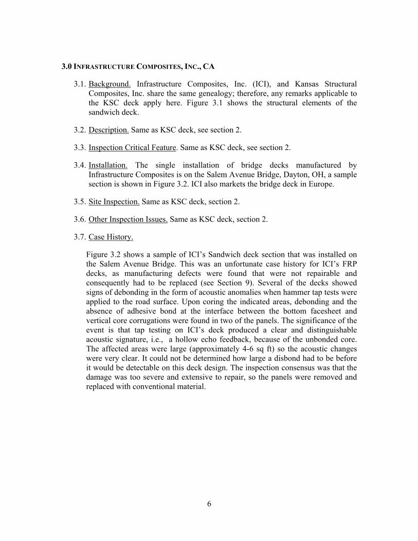
3.1. Background. Infrastructure Composites, Inc. (ICI), and Kansas Structural Composites, Inc. share the same genealogy; therefore, any remarks applicable to the KSC deck apply here. Figure 3.1 shows the structural elements of the sandwich deck.
3.2. Description. Same as KSC deck, see section 2.
3.3. Inspection Critical Feature. Same as KSC deck, see section 2.
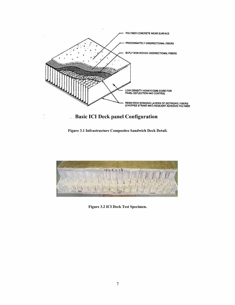
3.4. Installation. The single installation of bridge decks manufactured by Infrastructure Composites is on the Salem Avenue Bridge, Dayton, OH, a sample section is shown in Figure 3.2. ICI also markets the bridge deck in Europe.
3.5. Site Inspection. Same as KSC deck, section 2.
3.6. Other Inspection Issues. Same as KSC deck, section 2.
3.7. Case History.
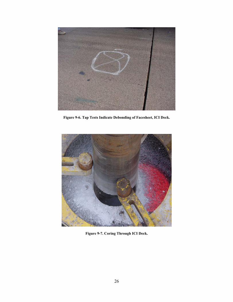
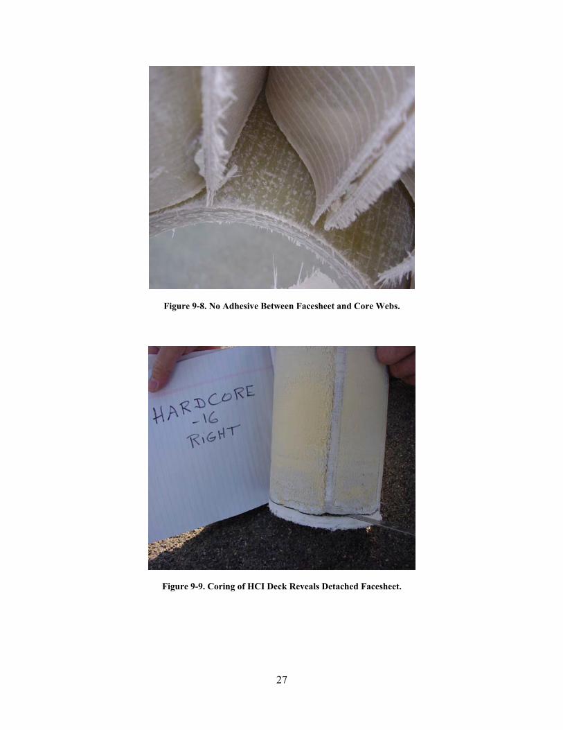
Figure 3.2 shows a sample of ICI’s Sandwich deck section that was installed on the Salem Avenue Bridge. This was an unfortunate case history for ICI’s FRP decks, as manufacturing defects were found that were not repairable and consequently had to be replaced (see Section 9). Several of the decks showed signs of debonding in the form of acoustic anomalies when hammer tap tests were applied to the road surface. Upon coring the indicated areas, debonding and the absence of adhesive bond at the interface between the bottom facesheet and vertical core corrugations were found in two of the panels. The significance of the event is that tap testing on ICI’s deck produced a clear and distinguishable acoustic signature, i.e., a hollow echo feedback, because of the unbonded core. The affected areas were large (approximately 4-6 sq ft) so the acoustic changes were very clear. It could not be determined how large a disbond had to be before it would be detectable on this deck design. The inspection consensus was that the damage was too severe and extensive to repair, so the panels were removed and replaced with conventional material.
7
Figure 3.1 Infrastructure Composites Sandwich Deck Detail.
Figure 3.2 ICI Deck Test Specimen.
8
4.0 MARTIN MARIETTA COMPOSITES, INC., NC
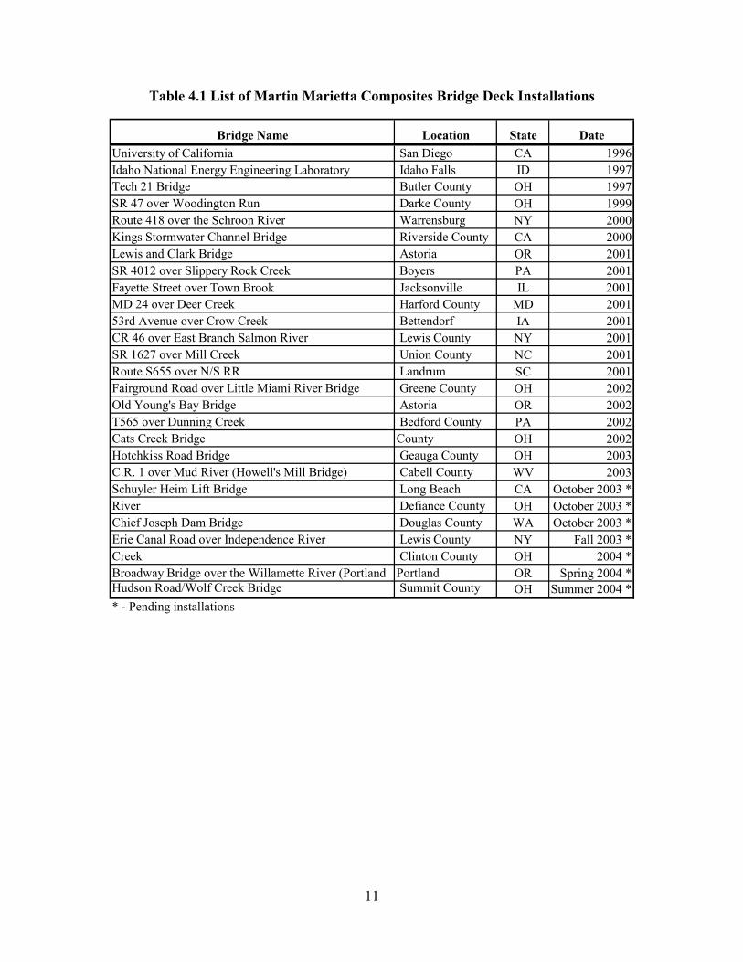
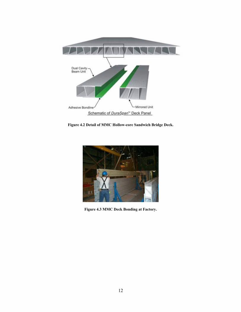
4.1. Background. Martin Marietta Composites (MMC), Raleigh, NC, markets a line of FRP composite bridge decks under the DURASPAN trademark. Figure 4.1 shows the cross-section of its current line of 8” and 5” decks which may be laminated with additional facesheets if necessary to meet stiffness and deflection requirements. MMC’s entry into the composite bridge deck market began with its acquisition of the technology from Lockheed Martin Corporation in 1996. Since then, MMC has been involved with research and development projects sponsored by various Federal and State agencies in supplying and testing several generations of DURASPAN decks. Table 4.1 lists over 20 completed installation and seven pending installations to date. Most of the installations with the exception of the Schuyler Heim Lift Bridge project [5] and a few others categorized as in-progress employ the DURASPAN fiberglass reinforced cross-sections.
4.2. Description. The DURASPAN deck system consists of a base trapezoid cross-sectional piece manufactured by the pultrusion process. Pultrusion is an automated manufacturing process where tightly packed strands and cloth forms of fiberglass reinforcements are saturated in liquid resin and then drawn through a heated metal die. The effect is a dimensionally close-tolerance, constant cross-sectional piece. Similar to metal extrusions, pultruded pieces are drawn continuously and cut to length on-line. This makes for consistent quality control. Because of controlled heating and compaction, the resin properties are typically at the high end of the strength and temperature resistivity range.
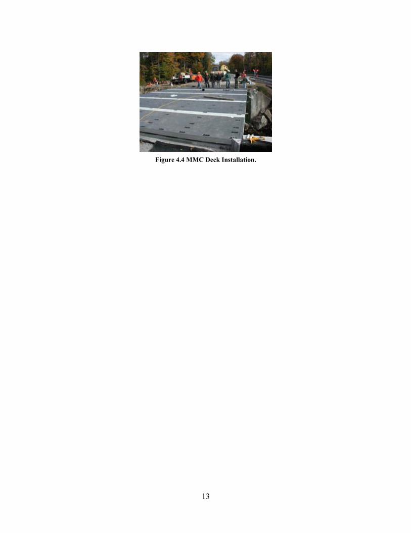
A DURASPAN deck is post-assembled to delivered width by bonding the unit pieces with epoxy or urethane adhesive applied to the tongue–and-groove connection and press-fit until cured. Additional facesheet may be applied to the contiguous top and bottom surface if more stiffness is desired.
4.3. Inspection Critical Features. Prior to assembly, the unit sections are inspected by the manufacturer for fabrication defects by visual and other general inspection methods available for composite materials. During assembly, the finished decks are inspected for quality. The critical areas for inspection are:
• The surface and the bond quality of the lapped joints bonded at the factory. The bond joints may not be visible if additional layers are laminated across the surface or if a wear surface is installed.
• In the case of wear surfaces, the obvious check would be for adhesion strength between the wear surface and pultruded members.
• If spalling or long cracks are evident in the wear surface, that would be a sign of potential problems.
• The manufactured thickness of the top and bottom skins makes it unlikely for delaminations to occur outside the bondline area. Most likely flaw over
9
time is a debonding of the lapped flanges between pultruded sections if too little glue was applied at the joint.
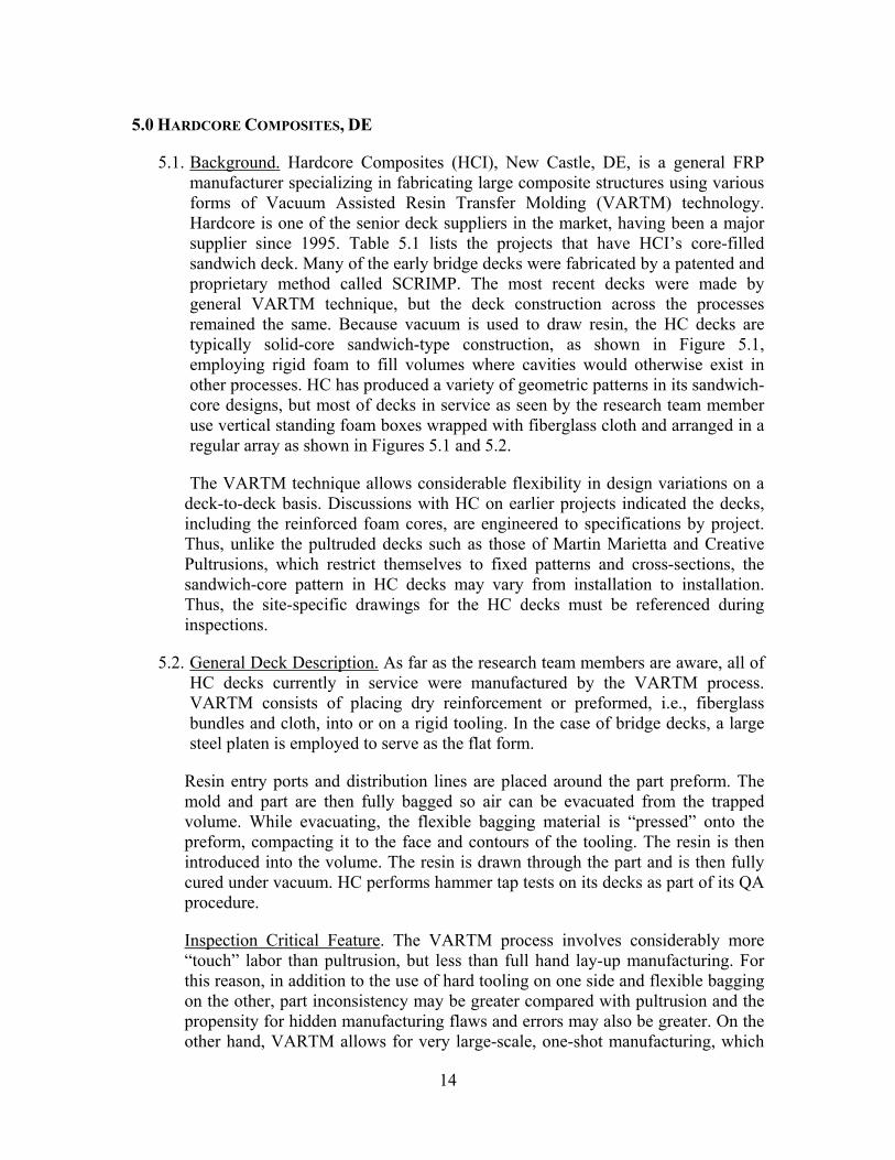
4.4. Installation. Typical installation of the DURASPAN deck as currently practiced by MMC unless requested otherwise is to pre-core connection holes into the deck in a pattern coincident with the support structure. Most installations have used shear stud connections similar to prefabricated concrete slab installations, where the deck is locked onto the superstructure by welding the shear stud to the top of the girder through the holes, then casting concrete grout fill into the hole to fully embed the stud. MMC has indicated the deck and girder interaction due to thermal expansion has not been a problem in all their previous projects employing the connection. Reflective cracks have been observed in thinly applied wear surfaces around the connections. But gross pop-off or spalling of wear surface has not been a problem if surface preparation procedures are followed. Asphalt has been routinely applied to the decks, and on a few decks problems occurred that were traced to improper installation procedures. MMC now applies a precoat of grit material before asphalt installation to eliminate potential adhesion problems.
4.5. Site Inspection. The critical areas for inspection after installation are:
• Bumps or irregular surface features which may indicate disbond at the connection between decks.
• Larger than typical gaps on the underside of the deck along the haunch contact areas. This may indicate loosening of the shear stud connections from failing grout, thus resulting in unrestrained rise of the deck from thermal growth.
• Water leaks indicating water incursion into cell cavities. • Wear surface cracks or peeling.
4.6. Other Inspection Issues. The DURASPAN deck sections are nominally thicker and have higher fiber density than other fabrication methods, so would exhibit more stable dimensional behavior over varying exposure and seasonal environments. Discussions with MMC engineers have indicated no serious problems with the deck structure of previous installations. The recently developed 5”-thick deck cross-section has similar thickness flanges as the 8” cross-section, which makes it equally resistant to internal damage under normal traffic loading. Many of the problems that have occurred have been with wear surface integrity and observable rises and falls of the deck surface under extreme ambient temperatures.
4.7. Case Histories.
• No direct damage or failures of the composite decks have been reported in any of the MMC deck installations.
10
• Two incidences of wear surface failures on the bridge in Darke County, OH and a lift bridge in OR have been traced to improper installation procedures and not to compatibility with deck materials. The wear surfaces were properly replaced and have shown no problems thereafter.
• Earliest known composite decks installed on the University of San Diego campus in 1996 remain functional and exhibit no deck or wear surface problems.
• The Tech 21 bridge installed in Butler County, OH, 1997, has an asphalt wear surface. Only problem observed has been transverse cracking of the asphalt on the contact face of the bridge to approach ramp due to thermal expansion. Bridge and asphalt wear surface on the bridge have shown no signs of problems since its opening.
• The King Stormwater Channel Bridge in Riverside County, CA, 2000, has exhibited wear surface cracking due to severe temperature expansion/contraction in the desert environment. However, the cracks are confined to near abutment areas and show no indications of propagation. Cracks are being monitored and no repairs are currently planned.
11
Table 4.1 List of Martin Marietta Composites Bridge Deck Installations
Bridge Name Location State DateUniversity of California San Diego CA 1996Idaho National Energy Engineering Laboratory Idaho Falls ID 1997Tech 21 Bridge Butler County OH 1997SR 47 over Woodington Run Darke County OH 1999Route 418 over the Schroon River Warrensburg NY 2000Kings Stormwater Channel Bridge Riverside County CA 2000Lewis and Clark Bridge Astoria OR 2001SR 4012 over Slippery Rock Creek Boyers PA 2001Fayette Street over Town Brook Jacksonville IL 2001MD 24 over Deer Creek Harford County MD 200153rd Avenue over Crow Creek Bettendorf IA 2001CR 46 over East Branch Salmon River Lewis County NY 2001SR 1627 over Mill Creek Union County NC 2001Route S655 over N/S RR Landrum SC 2001Fairground Road over Little Miami River Bridge Greene County OH 2002Old Young's Bay Bridge Astoria OR 2002T565 over Dunning Creek Bedford County PA 2002Cats Creek Bridge County OH 2002Hotchkiss Road Bridge Geauga County OH 2003C.R. 1 over Mud River (Howell's Mill Bridge) Cabell County WV 2003Schuyler Heim Lift Bridge Long Beach CA October 2003 *River Defiance County OH October 2003 *Chief Joseph Dam Bridge Douglas County WA October 2003 *Erie Canal Road over Independence River Lewis County NY Fall 2003 *Creek Clinton County OH 2004 *Broadway Bridge over the Willamette River (Portland Portland OR Spring 2004 *Hudson Road/Wolf Creek Bridge Summit County OH Summer 2004 ** - Pending installations
12
Figure 4.2 Detail of MMC Hollow-core Sandwich Bridge Deck.
Figure 4.3 MMC Deck Bonding at Factory.
13
Figure 4.4 MMC Deck Installation.
14
5.0 HARDCORE COMPOSITES, DE
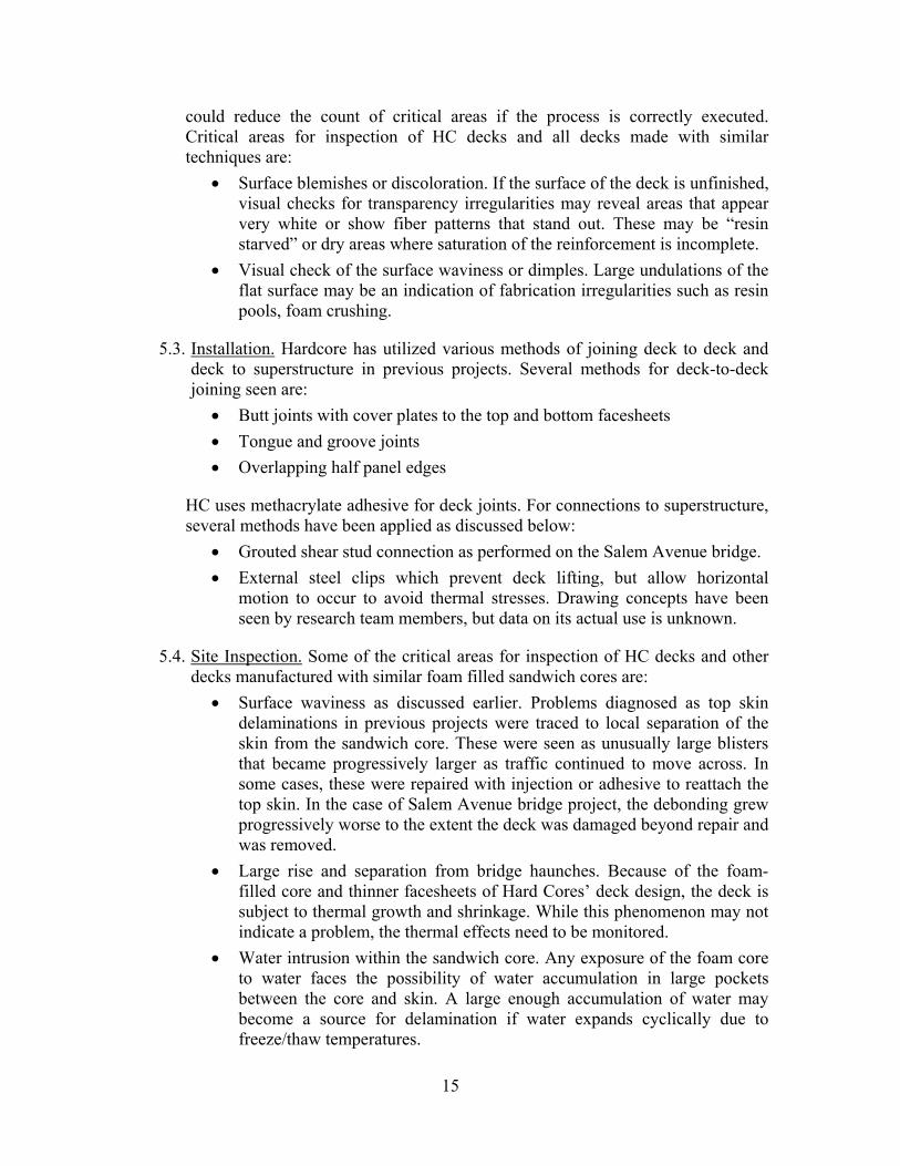
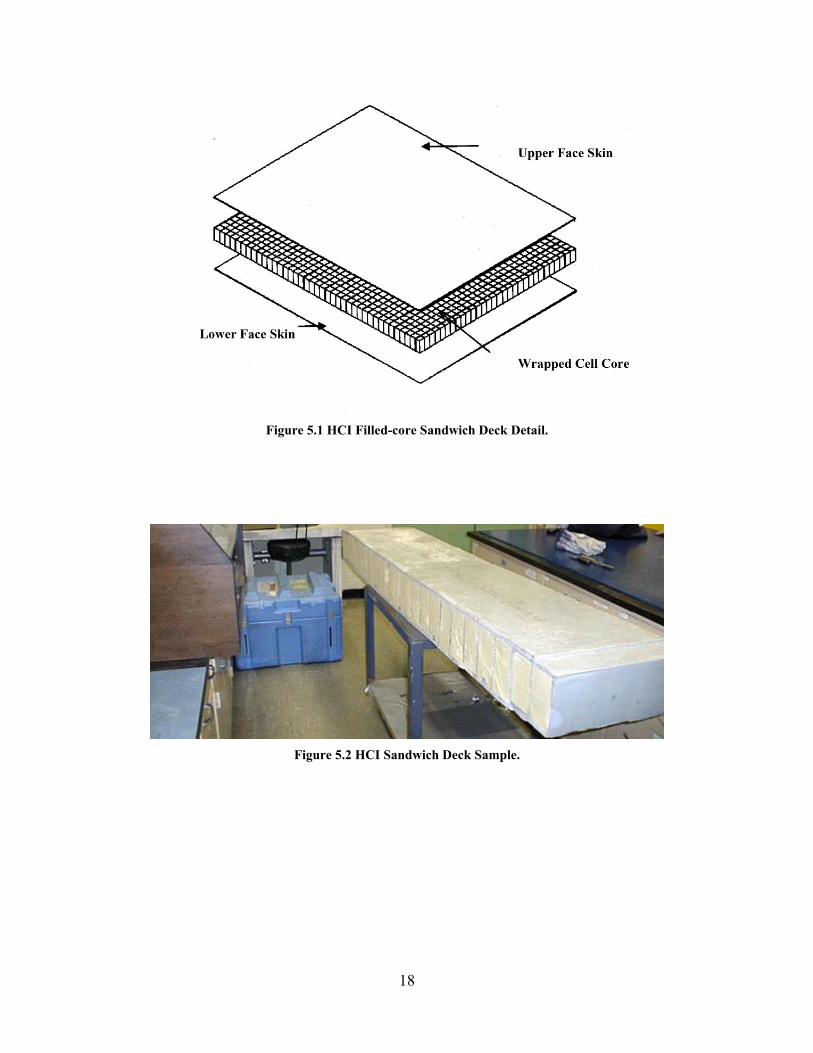
5.1. Background. Hardcore Composites (HCI), New Castle, DE, is a general FRP manufacturer specializing in fabricating large composite structures using various forms of Vacuum Assisted Resin Transfer Molding (VARTM) technology. Hardcore is one of the senior deck suppliers in the market, having been a major supplier since 1995. Table 5.1 lists the projects that have HCI’s core-filled sandwich deck. Many of the early bridge decks were fabricated by a patented and proprietary method called SCRIMP. The most recent decks were made by general VARTM technique, but the deck construction across the processes remained the same. Because vacuum is used to draw resin, the HC decks are typically solid-core sandwich-type construction, as shown in Figure 5.1, employing rigid foam to fill volumes where cavities would otherwise exist in other processes. HC has produced a variety of geometric patterns in its sandwich-core designs, but most of decks in service as seen by the research team member use vertical standing foam boxes wrapped with fiberglass cloth and arranged in a regular array as shown in Figures 5.1 and 5.2.
The VARTM technique allows considerable flexibility in design variations on a deck-to-deck basis. Discussions with HC on earlier projects indicated the decks, including the reinforced foam cores, are engineered to specifications by project. Thus, unlike the pultruded decks such as those of Martin Marietta and Creative Pultrusions, which restrict themselves to fixed patterns and cross-sections, the sandwich-core pattern in HC decks may vary from installation to installation. Thus, the site-specific drawings for the HC decks must be referenced during inspections.
5.2. General Deck Description. As far as the research team members are aware, all of HC decks currently in service were manufactured by the VARTM process. VARTM consists of placing dry reinforcement or preformed, i.e., fiberglass bundles and cloth, into or on a rigid tooling. In the case of bridge decks, a large steel platen is employed to serve as the flat form.
Resin entry ports and distribution lines are placed around the part preform. The mold and part are then fully bagged so air can be evacuated from the trapped volume. While evacuating, the flexible bagging material is “pressed” onto the preform, compacting it to the face and contours of the tooling. The resin is then introduced into the volume. The resin is drawn through the part and is then fully cured under vacuum. HC performs hammer tap tests on its decks as part of its QA procedure.
Inspection Critical Feature. The VARTM process involves considerably more “touch” labor than pultrusion, but less than full hand lay-up manufacturing. For this reason, in addition to the use of hard tooling on one side and flexible bagging on the other, part inconsistency may be greater compared with pultrusion and the propensity for hidden manufacturing flaws and errors may also be greater. On the other hand, VARTM allows for very large-scale, one-shot manufacturing, which
15
could reduce the count of critical areas if the process is correctly executed. Critical areas for inspection of HC decks and all decks made with similar techniques are:
• Surface blemishes or discoloration. If the surface of the deck is unfinished, visual checks for transparency irregularities may reveal areas that appear very white or show fiber patterns that stand out. These may be “resin starved” or dry areas where saturation of the reinforcement is incomplete.
• Visual check of the surface waviness or dimples. Large undulations of the flat surface may be an indication of fabrication irregularities such as resin pools, foam crushing.
5.3. Installation. Hardcore has utilized various methods of joining deck to deck and deck to superstructure in previous projects. Several methods for deck-to-deck joining seen are:
• Butt joints with cover plates to the top and bottom facesheets • Tongue and groove joints • Overlapping half panel edges
HC uses methacrylate adhesive for deck joints. For connections to superstructure, several methods have been applied as discussed below:
• Grouted shear stud connection as performed on the Salem Avenue bridge. • External steel clips which prevent deck lifting, but allow horizontal
motion to occur to avoid thermal stresses. Drawing concepts have been seen by research team members, but data on its actual use is unknown.
5.4. Site Inspection. Some of the critical areas for inspection of HC decks and other decks manufactured with similar foam filled sandwich cores are:
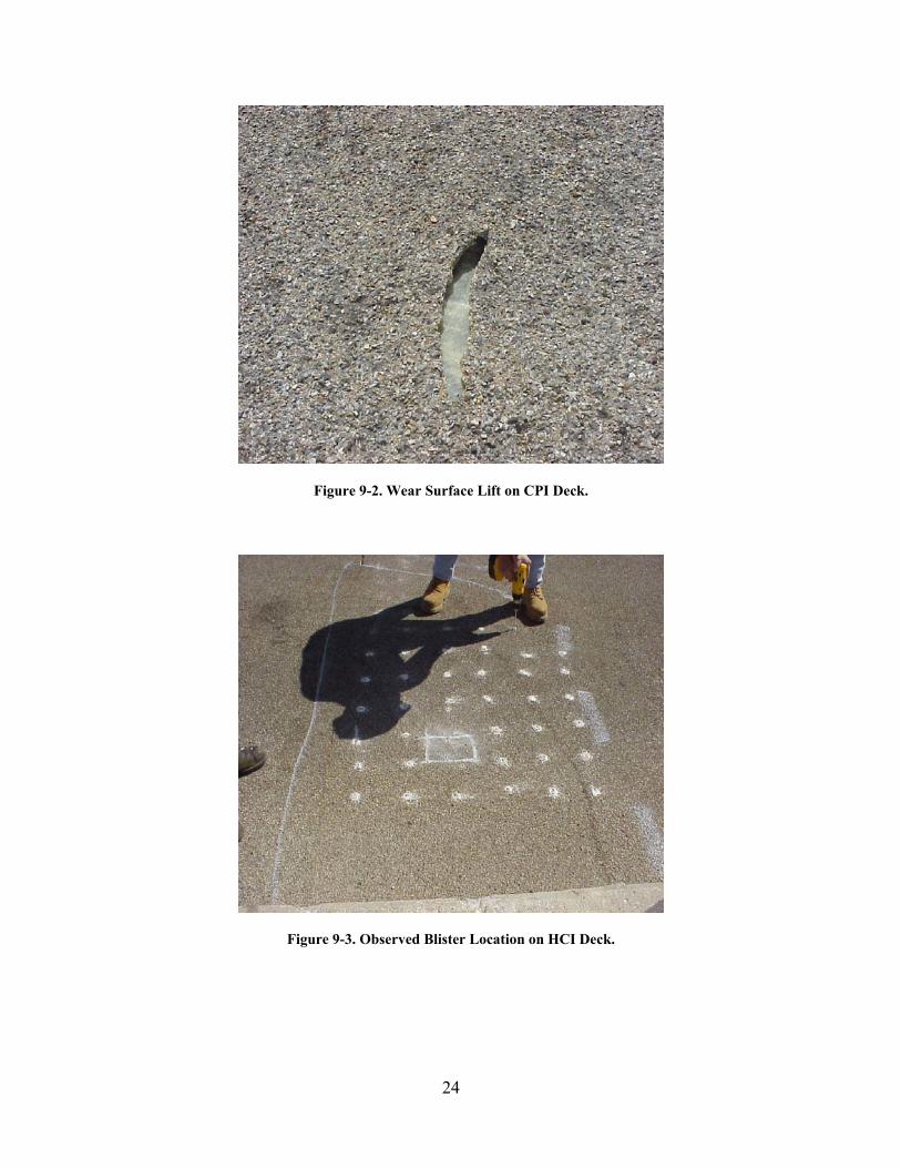
• Surface waviness as discussed earlier. Problems diagnosed as top skin delaminations in previous projects were traced to local separation of the skin from the sandwich core. These were seen as unusually large blisters that became progressively larger as traffic continued to move across. In some cases, these were repaired with injection or adhesive to reattach the top skin. In the case of Salem Avenue bridge project, the debonding grew progressively worse to the extent the deck was damaged beyond repair and was removed.
• Large rise and separation from bridge haunches. Because of the foam-filled core and thinner facesheets of Hard Cores’ deck design, the deck is subject to thermal growth and shrinkage. While this phenomenon may not indicate a problem, the thermal effects need to be monitored.
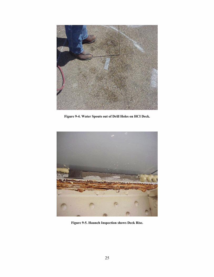
• Water intrusion within the sandwich core. Any exposure of the foam core to water faces the possibility of water accumulation in large pockets between the core and skin. A large enough accumulation of water may become a source for delamination if water expands cyclically due to freeze/thaw temperatures.
16
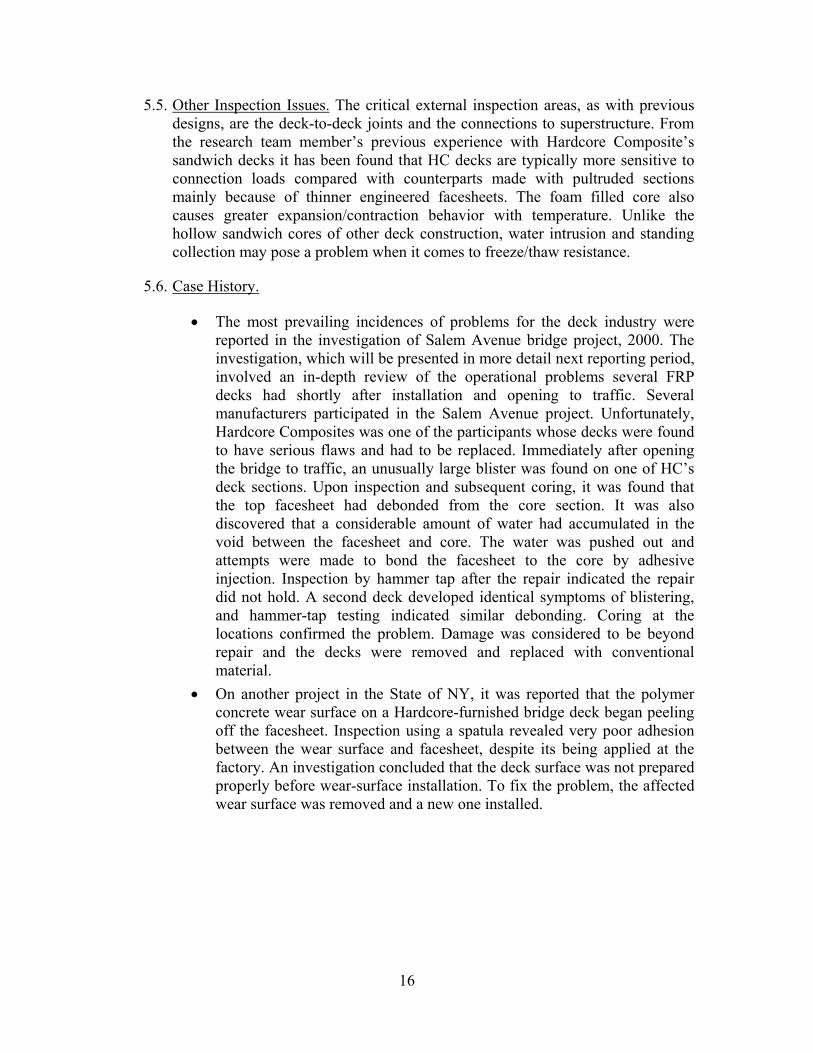
5.5. Other Inspection Issues. The critical external inspection areas, as with previous designs, are the deck-to-deck joints and the connections to superstructure. From the research team member’s previous experience with Hardcore Composite’s sandwich decks it has been found that HC decks are typically more sensitive to connection loads compared with counterparts made with pultruded sections mainly because of thinner engineered facesheets. The foam filled core also causes greater expansion/contraction behavior with temperature. Unlike the hollow sandwich cores of other deck construction, water intrusion and standing collection may pose a problem when it comes to freeze/thaw resistance.
5.6. Case History.
• The most prevailing incidences of problems for the deck industry were reported in the investigation of Salem Avenue bridge project, 2000. The investigation, which will be presented in more detail next reporting period, involved an in-depth review of the operational problems several FRP decks had shortly after installation and opening to traffic. Several manufacturers participated in the Salem Avenue project. Unfortunately, Hardcore Composites was one of the participants whose decks were found to have serious flaws and had to be replaced. Immediately after opening the bridge to traffic, an unusually large blister was found on one of HC’s deck sections. Upon inspection and subsequent coring, it was found that the top facesheet had debonded from the core section. It was also discovered that a considerable amount of water had accumulated in the void between the facesheet and core. The water was pushed out and attempts were made to bond the facesheet to the core by adhesive injection. Inspection by hammer tap after the repair indicated the repair did not hold. A second deck developed identical symptoms of blistering, and hammer-tap testing indicated similar debonding. Coring at the locations confirmed the problem. Damage was considered to be beyond repair and the decks were removed and replaced with conventional material.
• On another project in the State of NY, it was reported that the polymer concrete wear surface on a Hardcore-furnished bridge deck began peeling off the facesheet. Inspection using a spatula revealed very poor adhesion between the wear surface and facesheet, despite its being applied at the factory. An investigation concluded that the deck surface was not prepared properly before wear-surface installation. To fix the problem, the affected wear surface was removed and a new one installed.
17
Table 5.1 List of Hardcore Composite Deck Installations
Bridge Name State/Prov DateMuddy River route 696 Delaware 1998 RI 248 over Bennetts Creek New York 1998 Magazine Ditch Bridge-Memorial Bridge Delaware 1997 Washington School House Road Maryland 1997 Wilson's Bridge Pennsylvania 1998 Greenbranch Vehicular Delaware 1999 Mill Creek Bridge Delaware 1999 RI 357 over Bentley Creek New York 1999 Salem Ave. Bridge (2)(State RI 49) Ohio 1999 Wheatly Road Maryland 2000 Cayuta Creek Bridge New York 2000 South Broad Street Bridge New York 2000 Sintz Road Bridge Ohio 2000 Five Mile Road Bridge # 0171 Ohio 2000 Eliot Run (Highway 114) Ohio 2000 West Brook Road Bridge over Dry Run Creek Ohio 2000 Snouffer School Road Maryland 2001 Triphammer Road over Conesus? Outlet New York 2001 Shaffer Road BRidge Ohio 2001 Five Mile Road Bridge # 67 Ohio 2001 Five Mile Road Bridge #71 Ohio 2001 Spaulding Road Bridge Ohio 2001 SR 1037 over Dubois Creek Pennsylvania 2001 Montrose Bridge West Virginia 2001 Boy Scout Bridge West Virginia 2001 County Road 153 New York 2002
18
Figure 5.1 HCI Filled-core Sandwich Deck Detail.
Figure 5.2 HCI Sandwich Deck Sample.
19
6.0 CREATIVE PULTRUSIONS, PA/WEST VIRGINIA UNIVERSITY
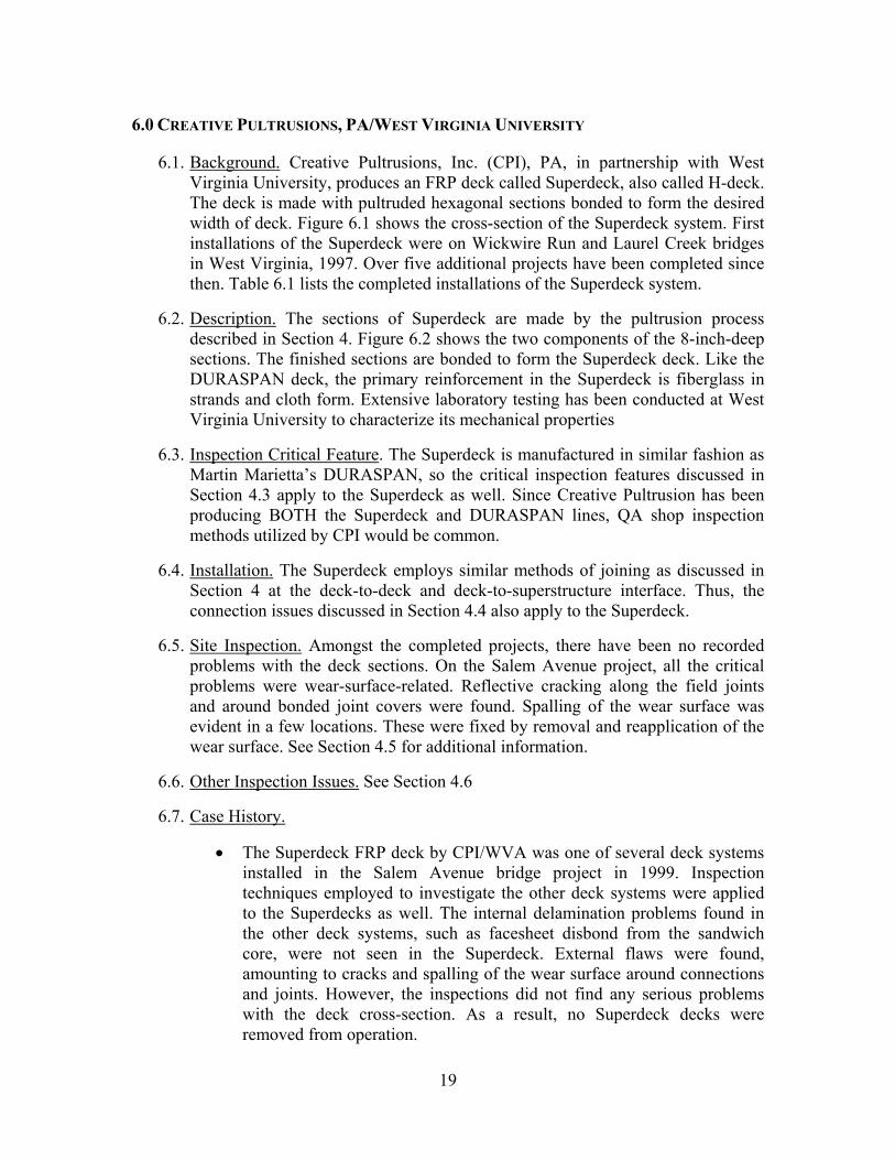
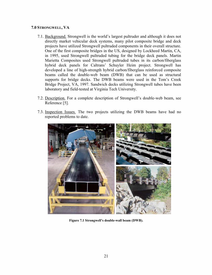
6.1. Background. Creative Pultrusions, Inc. (CPI), PA, in partnership with West Virginia University, produces an FRP deck called Superdeck, also called H-deck. The deck is made with pultruded hexagonal sections bonded to form the desired width of deck. Figure 6.1 shows the cross-section of the Superdeck system. First installations of the Superdeck were on Wickwire Run and Laurel Creek bridges in West Virginia, 1997. Over five additional projects have been completed since then. Table 6.1 lists the completed installations of the Superdeck system.
6.2. Description. The sections of Superdeck are made by the pultrusion process described in Section 4. Figure 6.2 shows the two components of the 8-inch-deep sections. The finished sections are bonded to form the Superdeck deck. Like the DURASPAN deck, the primary reinforcement in the Superdeck is fiberglass in strands and cloth form. Extensive laboratory testing has been conducted at West Virginia University to characterize its mechanical properties
6.3. Inspection Critical Feature. The Superdeck is manufactured in similar fashion as Martin Marietta’s DURASPAN, so the critical inspection features discussed in Section 4.3 apply to the Superdeck as well. Since Creative Pultrusion has been producing BOTH the Superdeck and DURASPAN lines, QA shop inspection methods utilized by CPI would be common.
6.4. Installation. The Superdeck employs similar methods of joining as discussed in Section 4 at the deck-to-deck and deck-to-superstructure interface. Thus, the connection issues discussed in Section 4.4 also apply to the Superdeck.
6.5. Site Inspection. Amongst the completed projects, there have been no recorded problems with the deck sections. On the Salem Avenue project, all the critical problems were wear-surface-related. Reflective cracking along the field joints and around bonded joint covers were found. Spalling of the wear surface was evident in a few locations. These were fixed by removal and reapplication of the wear surface. See Section 4.5 for additional information.
6.6. Other Inspection Issues. See Section 4.6
6.7. Case History.
• The Superdeck FRP deck by CPI/WVA was one of several deck systems installed in the Salem Avenue bridge project in 1999. Inspection techniques employed to investigate the other deck systems were applied to the Superdecks as well. The internal delamination problems found in the other deck systems, such as facesheet disbond from the sandwich core, were not seen in the Superdeck. External flaws were found, amounting to cracks and spalling of the wear surface around connections and joints. However, the inspections did not find any serious problems with the deck cross-section. As a result, no Superdeck decks were removed from operation.
20
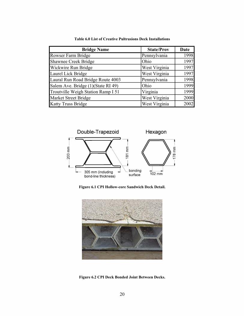
Table 6.0 List of Creative Pultrusions Deck Installations
Figure 6.1 CPI Hollow-core Sandwich Deck Detail.
Figure 6.2 CPI Deck Bonded Joint Between Decks.
Bridge Name State/Prov DateRowser Farm Bridge Pennsylvania 1998 Shawnee Creek Bridge Ohio 1997 Wickwire Run Bridge West Virginia 1997 Laurel Lick Bridge West Virginia 1997 Laural Run Road Bridge Route 4003 Pennsylvania 1998 Salem Ave. Bridge (1)(State RI 49) Ohio 1999 Troutville Weigh Station Ramp I 51 Virginia 1999 Market Street Bridge West Virginia 2000 Katty Truss Bridge West Virginia 2002
21
7.0 STRONGWELL, VA
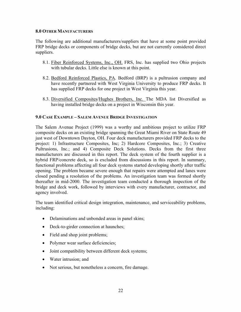
7.1. Background. Strongwell is the world’s largest pultruder and although it does not directly market vehicular deck systems, many pilot composite bridge and deck projects have utilized Strongwell pultruded components in their overall structure. One of the first composite bridges in the US, designed by Lockheed Martin, CA, in 1995, used Strongwell pultruded tubing for the bridge deck panels. Martin Marietta Composites used Strongwell pultruded tubes in its carbon/fiberglass hybrid deck panels for Caltrans’ Schuyler Heim project. Strongwell has developed a line of high-strength hybrid carbon/fiberglass reinforced composite beams called the double-web beam (DWB) that can be used as structural supports for bridge decks. The DWB beams were used in the Tom’s Creek Bridge Project, VA, 1997. Sandwich decks utilizing Strongwell tubes have been laboratory and field-tested at Virginia Tech University.
7.2. Description. For a complete description of Strongwell’s double-web beam, see Reference [5].
7.3. Inspection Issues. The two projects utilizing the DWB beams have had no reported problems to date.
Figure 7.1 Strongwell’s double-wall beam (DWB).
22
8.0 OTHER MANUFACTURERS
The following are additional manufacturers/suppliers that have at some point provided FRP bridge decks or components of bridge decks, but are not currently considered direct suppliers.
8.1. Fiber Reinforced Systems, Inc., OH. FRS, Inc. has supplied two Ohio projects with tubular decks. Little else is known at this point.
8.2. Bedford Reinforced Plastics, PA. Bedford (BRP) is a pultrusion company and have recently partnered with West Virginia University to produce FRP decks. It has supplied FRP decks for one project in West Virginia this year.
8.3. Diversified Composites/Hughes Brothers, Inc. The MDA list Diversified as having installed bridge decks on a project in Wisconsin this year.
9.0 CASE EXAMPLE – SALEM AVENUE BRIDGE INVESTIGATION
The Salem Avenue Project (1999) was a worthy and ambitious project to utilize FRP composite decks on an existing bridge spanning the Great Miami River on State Route 49 just west of Downtown Dayton, OH. Four deck manufacturers provided FRP decks to the project: 1) Infrastructure Composites, Inc; 2) Hardcore Composites, Inc.; 3) Creative Pultrusions, Inc.; and 4) Composite Deck Solutions. Decks from the first three manufacturers are discussed in this report. The deck system of the fourth supplier is a hybrid FRP/concrete deck, so is excluded from discussions in this report. In summary, functional problems affecting all four deck systems started developing shortly after traffic opening. The problem became severe enough that repairs were attempted and lanes were closed pending a resolution of the problems. An investigation team was formed shortly thereafter in mid-2000. The investigation team conducted a thorough inspection of the bridge and deck work, followed by interviews with every manufacturer, contractor, and agency involved.
The team identified critical design integration, maintenance, and serviceability problems, including:
• Delaminations and unbonded areas in panel skins;
• Deck-to-girder connection at haunches;
• Field and shop joint problems;
• Polymer wear surface deficiencies;
• Joint compatibility between different deck systems;
• Water intrusion; and
• Not serious, but nonetheless a concern, fire damage.
23
Remedies for each of the issues were developed and recommended. Many were correctible on site, but some deficiencies stemming from manufacturing flaws and installation quality control problems required considerable manufacturer intervention and repair. In the end, ODOT decided the cost of repair and downtime would be too high, so removing the damaged decks would be the better choice.
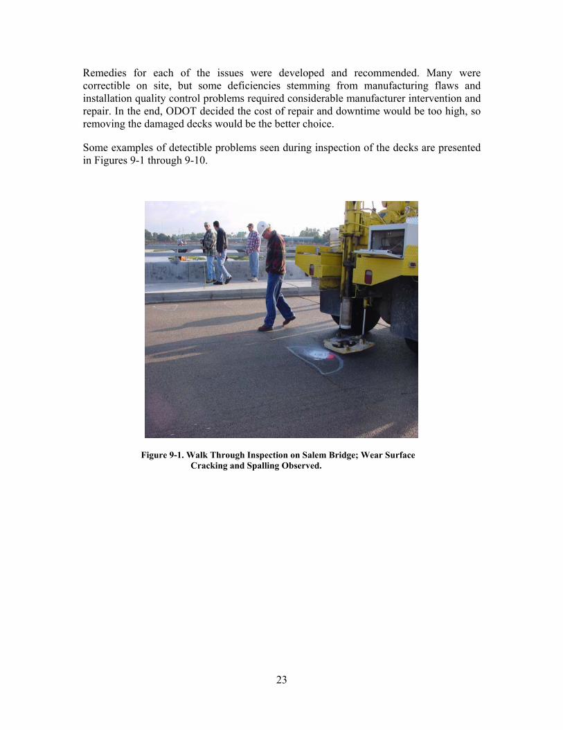
Some examples of detectible problems seen during inspection of the decks are presented in Figures 9-1 through 9-10.
Figure 9-1. Walk Through Inspection on Salem Bridge; Wear Surface Cracking and Spalling Observed.
24
Figure 9-2. Wear Surface Lift on CPI Deck.
Figure 9-3. Observed Blister Location on HCI Deck.
25
Figure 9-4. Water Spouts out of Drill Holes on HCI Deck.
Figure 9-5. Haunch Inspection shows Deck Rise.
26
Figure 9-6. Tap Tests Indicate Debonding of Facesheet, ICI Deck.
Figure 9-7. Coring Through ICI Deck.
27
Figure 9-8. No Adhesive Between Facesheet and Core Webs.
Figure 9-9. Coring of HCI Deck Reveals Detached Facesheet.
28
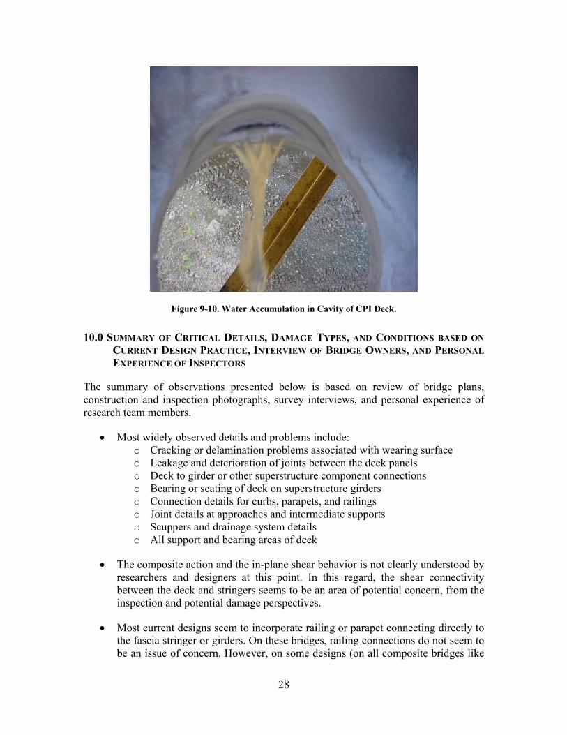
Figure 9-10. Water Accumulation in Cavity of CPI Deck.
10.0 SUMMARY OF CRITICAL DETAILS, DAMAGE TYPES, AND CONDITIONS BASED ON CURRENT DESIGN PRACTICE, INTERVIEW OF BRIDGE OWNERS, AND PERSONAL EXPERIENCE OF INSPECTORS
The summary of observations presented below is based on review of bridge plans, construction and inspection photographs, survey interviews, and personal experience of research team members.
• Most widely observed details and problems include: o Cracking or delamination problems associated with wearing surface o Leakage and deterioration of joints between the deck panels o Deck to girder or other superstructure component connections o Bearing or seating of deck on superstructure girders o Connection details for curbs, parapets, and railings o Joint details at approaches and intermediate supports o Scuppers and drainage system details o All support and bearing areas of deck
• The composite action and the in-plane shear behavior is not clearly understood by researchers and designers at this point. In this regard, the shear connectivity between the deck and stringers seems to be an area of potential concern, from the inspection and potential damage perspectives.
• Most current designs seem to incorporate railing or parapet connecting directly to the fascia stringer or girders. On these bridges, railing connections do not seem to be an issue of concern. However, on some designs (on all composite bridges like
29
the Kings Stormwater Bridge in California) the railing/parapet is connected to the deck. In these designs, potential for damage and need for inspection of these joints could be categorized as critical details.
• Moisture ingress leading to the possibility of freeze-thaw induced delamination seems to be also of some concern to the DOTs, and could be categorized into either Category 1 or 2 along with the issue of delamination of top skin from the core of the deck.
• The deck-to-deck connection is probably the most accessible part of the bridge deck and the most likely part of the deck system to develop problems because of improper installation, environmental swings, or excess loading. Experience with the Salem Avenue Bridge Project and ad hoc inspection/observation of bridge decks on the King Stormwater Canyon, Tech 21, and Darke County bridges have shown that the first instance of problems generally occur at the deck connections in the form of overlay/wear surface cracking or spall.
Other items that have not been researched extensively at this time include damage resulting from fire, chemicals, impact, UV, and moisture. Repercussions of such damages, inspection techniques to detect such damages, and quantifying the severity of such damages might require further research in these areas. In Appendix 5, typical connection details and failure patterns are presented.