Embed Size (px)
Citation preview

Summary Report: Expansion of the Vehicle Fuel System Database and Overview of Pickup Truck History
Report No.:
R04-02 – v02 Date:
2004 – 05 - 10 Status:
Public Prepared for:
Dr. Ken Digges Motor Vehicle Fire Research Institute 1334 Pendleton Court Charlottesvile, Virginia 22901
Authors:
Ed Fournier Jim Kot
Biokinetics and Associates Ltd. 2470 Don Reid Drive Ottawa, Ontario, K1H 1E1 Canada
tel: (613) 736-0384
fax: (613) 736-0990 www.biokinetics.com
Biokinetics and Associates Ltd. (2004)
Biokinetics and Associates Ltd. (2004) R04-02 v02.doc / May 10, 2004 / Page i
Preface
This report constitutes the final deliverable for Biokinetics and Associates’ contract with the Motor Vehicle Fire Research Institute to carry out the work described in Biokinetics’ proposal P03-98. The work comprised updating the vehicle inspection and tank inspection database to include data from additional vehicle and tank inspections, reviewing the model history of pickup trucks and identifying the usage rate of positive battery terminal insulators. Additionally, leakage tests were performed on a sample of vehicle fuel systems.
The opinions expressed herein are those of Biokinetics and Associates Ltd. and do not necessarily reflect those of the Motor Vehicle Fire Research Institute.
Biokinetics and Associates Ltd. (2004) R04-02 v02.doc / May 10, 2004 / Page ii
Table of Contents
1. Introduction............................................................................................................. 1
2. Additional Vehicle and Tank Inspections........................................................... 3
3. Historical Review of Pickup Truck Model Changes.......................................... 5
4. Insulated Positive Battery Terminals ................................................................. 15
5. Leak Tests............................................................................................................... 16 5.1 Observations: Leak Testing ....................................................................... 18
6. Summary ................................................................................................................ 19
7. References .............................................................................................................. 20
Appendix A : Leak Test Results................................................................................A-1

Biokinetics and Associates Ltd. (2004) R04-02 v02.doc / May 10, 2004 / Page iii
List of Figures and Tables
Figure 1: Chevrolet S10.................................................................................................... 6
Figure 2: Dodge Dakota................................................................................................... 7
Figure 3: Dodge Ram 1500. ............................................................................................. 8
Figure 4: Ford F150........................................................................................................... 9
Figure 5: Ford Ranger. ................................................................................................... 10
Figure 6: GMC Sierra. .................................................................................................... 11
Figure 7: Nissan Frontier............................................................................................... 11
Figure 8: Toyota Tacoma............................................................................................... 12
Figure 9: Toyota Tundra................................................................................................ 12
Figure 10: Typical test set-up for a leak test showing inversion of a tank system.................................................................................................... 16
Table 1: List of additional vehicles added to the database......................................... 3
Table 2: Four supplementary vehicles added to database. ........................................ 4
Table 3: Summary of insulating battery terminal cover usage................................ 15
Table 4: Summary of vehicles without insulated positive battery terminals........ 15
Table 5: Summary of leak test results.......................................................................... 17

Biokinetics and Associates Ltd. (2004) R04-02 v02.doc / May 10, 2004 / Page 1
1. Introduction
A database containing information pertaining to the installation of a vehicle’s fuel system was created under a prior contract with the Motor Vehicle Fire Research Institute. The objective of the database is to aid in identifying fuel system fire safety technologies for preventing and/or mitigating post-crash fires. The database comprises 74 vehicles, containing information such as the size and positioning measurements of the various fuel system components. Additional information related to the fuel line routing, the use of fire safety technologies and the proximity of potentially aggressive components is also documented. Photographs of the fuel system installations and of a select number of tank components are also included in the database. The database is described in more detail in Biokinetics Report R03-01 [Ref. 1].
Under a separate follow-on contract, the vehicles in the inspection database were matched with their sister models and corporate cousins, which raised the actual number of vehicles represented by the database to a total of 101 vehicles. Estimates of the North American vehicle sales for these vehicles were also established and it was determined that the 74 vehicle database was representative of 67% of 2003 vehicle sales comprising the North American Fleet [Ref. 2]. Further review of sales numbers indicated that the inclusion of the next 10 highest selling vehicles would raise the representation to 80%. The inclusion of these additional vehicles was accomplished as part of the work described herein.
Additional efforts to further support the understanding of the state-of-the-art in fuel system design technologies is reported herein. They include a historical review of pickup truck fuel system design, a determination of the usage rate of positive battery terminal insulating covers and physical leak tests on fuel tanks.
Research presented at the 2003 ESV conference [Ref. 3] suggested a significant drop in fatality rate in newer model pickup trucks compared with older models (early 90s) with fire/explosion coded as the most harmful event. A historical review of the fuel system components of 9 pickup trucks was performed to identify design changes that occurred during this period that may have influenced this trend. The introduction of fuel system fire safety technologies was specifically sought.
An insulating cover placed over the positive battery terminal is a recognized countermeasure for reducing electrical fires. The use of this feature was not specifically observed during the initial inspection of the database vehicles, however, for the majority of the vehicles it was possible to use the photographic documentation to identify the presence of an insulating cover. For those cases

Biokinetics and Associates Ltd. (2004) R04-02 v02.doc / May 10, 2004 / Page 2
where it could not be determined and for the additional vehicles added under the current effort, the use of an insulating cover was ascertained.
Leak testing performed on 20 fuel tanks is the final task of the current work that is reported on herein.

Biokinetics and Associates Ltd. (2004) R04-02 v02.doc / May 10, 2004 / Page 3
2. Additional Vehicle and Tank Inspections
Ten additional vehicles were inspected and included in the fuel system inspection database. The vehicles selected comprised those with the highest 2003 vehicle sales that were not initially included in the database. The ten additional vehicles are listed in Table 1 along with their reported sales for 2003. Note that the sales numbers reflect the total sales for each vehicle including the sales for their sister models.
Table 1: List of additional vehicles added to the database.
Vehicle
Make Model Classification
Sales for 2003
Chevrolet Impala Sedan/Coupe/Wagon 279,916
Chevrolet Trailblazer SUV 185,967
Ford Escape SUV 105,141
Chevrolet Suburban SUV 90,182
Chevrolet Malibu Sedan/Coupe/Wagon 79,224
Dodge Intrepid Sedan/Coupe/Wagon 72,433
Pontiac Vibe Sedan/Coupe/Wagon 63,546
Chrysler PT Cruiser Sedan/Coupe/Wagon 62,014
Toyota Highlander SUV 57,886
Saturn Ion Sedan/Coupe/Wagon 56,530
The inclusion of these vehicles in the database raises the total number of vehicles to 84 and if the sister models and corporate cousins are included the total number of vehicles represented by the database becomes 121. In terms of total vehicle sales, representation increases from 67% up to 80% of the 2003 North American sales. Representation within the Sedan/Coupe/Wagon and the SUV vehicles classifications also increased from 61% and 50% to 76% and 72% respectively. Representation in the pick-up truck, mini-van and full-size van vehicle classes remain unchanged at 95%, 94% and 98% respectively.
Four supplementary vehicles from the 2000 model year were also inspected and added to the database. These four vehicles, listed in Table 2, were included since the first one, combined with its sister models, exhibit comparatively high fire rates and the remaining three exhibit comparatively low fire rates [Ref. 4]. The

Biokinetics and Associates Ltd. (2004) R04-02 v02.doc / May 10, 2004 / Page 4
circumstances surrounding the high incidences of fire requires further investigation as it is not clear what the primary source/cause of fire is and whether or not it is related to the fuel system.
Table 2: Four supplementary vehicles added to database.
Vehicle
Make Model
Incidence of Fire
Dodge Stratus High
Mercury Grand Marquis Low
Honda Accord Low
Toyota Corolla Low
With the addition of these 4 vehicles and consideration of the sister models and their corporate cousins, the total number of vehicles represented by the database becomes 129.
Of the 14 vehicles that have been inspected and included in the database under the current effort, a more detailed tank component inspection was performed on the four vehicles from the 2000 model year. Additionally, an inspection of the Dodge SX2.0 (Neon) fuel system components was also performed1. The tank inspections were performed following the checklist used in the initial detailed tank component evaluations and the information, including photographs, was included in the vehicle inspection database.
1 The Neon is amongst the vehicles with the highest incidence of post crash fires. An inspection of the Dodge SX2.0 (Neon) was previously performed and was already included in the database.

Biokinetics and Associates Ltd. (2004) R04-02 v02.doc / May 10, 2004 / Page 5
3. Historical Review of Pickup Truck Model Changes
Research presented at the 2003 ESV conference [Ref. 3] suggested a significant drop in fatality rate in newer model pickup trucks compared with older models (early 90s) where fire/explosion was coded as the most harmful event. A historical review of the 9 pickup trucks contained in the database was performed to identify changes related to the fuel systems dating back to 1991. This data will be compared to the results of a statistical analysis of both Federal and State accident databases identifying fire rates for each pickup truck from 1991 onwards2. The objective of the comparisons will be to determine if a correlation exists between the introduction or the change of a fuel system feature with changes in fire rates.
The 9 current model pickup trucks from the database whose model history was reviewed include:
• Chevrolet S-10 • Dodge Dakota • Dodge Ram 1500 • Ford F150 • Ford Ranger • GMC Sierra • Nissan Frontier • Toyota Tacoma • Toyota Tundra
Specific vehicle component or design features that were reviewed include: • Gas tank • Tank location • Filler cap • Filler neck and tube • Fuel sender • Sender retainer • Rollover valve • Check valve • Battery location • Battery terminal cover • Under hood insulation • Fuel pump shut-off • Fuel line routing • Carburetion versus fuel injection
2 The statistical analysis will be performed by Friedman Research Corporation.

Biokinetics and Associates Ltd. (2004) R04-02 v02.doc / May 10, 2004 / Page 6
Vehicle information was obtained from various sources that included the vehicle inspection database, Haynes repair manuals, dealer service manuals, service technicians’ knowledge and the Mitchell PartsPoint database. Where possible the actual OEM fuel tanks which were installed in the late model year trucks were purchased for inspection. The historical data is summarized in Figure 1 to Figure 9. A colour change in the column for a given feature represents a change that has been identified from at least one of the information sources. The specific details of a change are not necessarily known and the colour has no reflection on quality or performance. For example, the evolution of a component may be identified by a change in part number but the specific change to the part may not be determined.
Yea
r
Mod
elG
as T
ank
Tank
Loc
atio
nFi
ller C
apFi
ller N
eck/
Tube
(3)
Fuel
Sen
der (
2)S
ende
r Ret
aine
rR
oll-o
ver V
alve
Che
ck V
alve
Bat
tery
Loc
atio
nB
atte
ry T
erm
inal
Cov
erU
nder
Hoo
d In
sula
tion
Fuel
Pum
p S
hut-o
ff (1
)Fu
el L
ine
Rou
ting
Car
bure
tion/
Fuel
Inje
ctio
n
2003 p I/ Y Y EC/ N Y Y AF FI Legend:2002 FR/ F/ AF -along frame2001 S L U R AR -aft of rear axle2000 N C - carbureted1999 EC -engine compartment1998 F - front1997 FI - fuel injection1996 FR - forward rear axle1995 I - inside frame rail1994 L - left side1993 Y C/FI M - mid1992 N - none1991 O - outside frame rail
P - plasticR - right side S - steelU - unknownY - yes
Note:(1) The fuel pump was relay controlled.(2) 1991 fuel tank sender seal was out of position and could leak in a rollover.(3) 1994 tank filler pipes were improperly manufactured and could cause the fuel tank filler pipes and vent tube to crack.
Figure 1: Chevrolet S10.

Biokinetics and Associates Ltd. (2004) R04-02 v02.doc / May 10, 2004 / Page 7
Yea
r
Mod
elG
as T
ank
Tank
Loc
atio
n (3
)Fi
ller C
apFi
ller N
eck/
Tube
Fuel
Sen
der
Sen
der R
etai
ner
Rol
l-ove
r Val
veC
heck
Val
veB
atte
ry L
ocat
ion
Bat
tery
Ter
min
al C
over
Und
er H
ood
Insu
latio
nFu
el P
ump
Shu
t-off
(1)
Fuel
Lin
e R
outin
g (2
, 4)
Car
bure
tion/
Fuel
Inje
ctio
n
2003 P I/ Y Y EC/ Y N Y AF/ FI Legend:2002 FR/ F/ L AF - along frame2001 L L Y AR -aft of rear axle2000 C - carbureted1999 EC -engine compartment1998 F - front1997 FI - fuel injection1996 U N FR - forward rear axle1995 I - inside frame rail1994 L - left side1993 N M - mid1992 N - none1991 O - outside frame rail
P - plasticR - right side S - steelU - unknownY - yes
Note:(1) The fuel pump was relay controlled.(2) 1991 Contact between braided fuel hoses and the transmission wiring harness could cause damage to the fuel hose resulting in a fuel leak.(3) 1994 Fuel tank mounting straps were improperly tightened and could allow the tank to shift or allow complete separation from the vehicle.(4) 1997 131 inch wheelbase vehicles may have inadequate clearance between the fuel line and the cab underbody which could result in a perforation.
Figure 2: Dodge Dakota.

Biokinetics and Associates Ltd. (2004) R04-02 v02.doc / May 10, 2004 / Page 8
Yea
r
Mod
elG
as T
ank
(1)
Tank
Loc
atio
n (5
)Fi
ller C
apFi
ller N
eck/
Tube
Fuel
Sen
der
Sen
der R
etai
ner
Rol
l-ove
r Val
ve (2
, 3)
Che
ck V
alve
Bat
tery
Loc
atio
nB
atte
ry T
erm
inal
Cov
erU
nder
Hoo
d In
sula
tion
Fuel
Pum
p S
hut-o
ff (4
)Fu
el L
ine
Rou
ting
(6)
Car
bure
tion/
Fuel
Inje
ctio
n
2003 P I/ Y Y EC/ Y Y Y AF/ FI Legend:2002 FR/ F/ L AF - along frame2001 L U L AR -aft of rear axle2000 C - carbureted1999 EC -engine compartment1998 F - front1997 Y FI - fuel injection1996 N FR - forward rear axle1995 I - inside frame rail1994 L - left side1993 N N M - mid1992 N - none1991 O - outside frame rail
P - plasticR - right side S - steelU - unknownY - yes
Note:(1) Within each change there are various tank capacity options.(2) Recall on 1994, 1995 and 1996 roll-over valves. Under certain vehicle operating conditions the rollover valve can allow fuel to leak. Rollover valves were replaced with float type valves. (3) The roll-over valve was part of the sending unit.(4) The fuel pump was relay controlled.(5) 94 models did not meet FMVSS 301 rear impact requirements.(6) 98 models had a heat shield screw that could rub on an underbody fuel line possibly causing fuel leaks.
Figure 3: Dodge Ram 1500.

Biokinetics and Associates Ltd. (2004) R04-02 v02.doc / May 10, 2004 / Page 9
Yea
r
Mod
elG
as T
ank
Tank
Loc
atio
n (1
)Fi
ller C
apFi
ller N
eck/
Tube
(2)
Fuel
Sen
der (
3) (6
)S
ende
r Ret
aine
rR
oll-o
ver V
alve
Che
ck V
alve
(4)
Bat
tery
Loc
atio
nB
atte
ry T
erm
inal
Cov
erU
nder
Hoo
d In
sula
tion
Fuel
Pum
p S
hut-o
ff (5
)Fu
el L
ine
Rou
ting
(7, 8
)C
arbu
retio
n/Fu
el In
ject
ion
2003 S I/ Y Y EC/ Y Y Y AF/ FI Legend:2002 FR/ M/ L AF - along frame2001 L R AR -aft of rear axle2000 C - carbureted1999 EC -engine compartment1998 F - front1997 FI - fuel injection1996 I/ N EC/ FR - forward rear axle1995 AR F/ I - inside frame rail1994 R L - left side1993 M - mid1992 N - none1991 O - outside frame rail
P - plasticR - right side S - steelU - unknownY - yes
Note:(1) From 1991 to 1996 both a midship and aft axle tank were available. The midship tank was the same from 91-96. The aft axle tank changed between 91 and 92-96.(2) The same filler neck/tube was used for the midship and the aft axle tank.(3) The fuel pump was the same but the gage changed in 92.(4) The check valve was located in the filler neck.(5) The fuel pump shut-off is inertially activated.(6) 1990 to 1993 a malfunctioning check valve within the fuel pump caused unused fuel to be returned to the second tank which could result in over filling and fuel spillage.(7) 1999 possibility that a fuel pressure regulator O-ring may have been damage during installation in the fuel rail which may allow vapor or fuel to leak.(8) 1997 In some vehicles rubbing on the fuel line may result in a fuel leak.
Figure 4: Ford F150.

Biokinetics and Associates Ltd. (2004) R04-02 v02.doc / May 10, 2004 / Page 10
Yea
r
Mod
elG
as T
ank
Tank
Loc
atio
n (1
)Fi
ller C
apFi
ller N
eck/
Tube
(2)
Fuel
Sen
der (
3) (6
)S
ende
r Ret
aine
rR
oll-o
ver V
alve
Che
ck V
alve
(4)
Bat
tery
Loc
atio
nB
atte
ry T
erm
inal
Cov
erU
nder
Hoo
d In
sula
tion
Fuel
Pum
p S
hut-o
ff (5
)Fu
el L
ine
Rou
ting
(7, 8
)C
arbu
retio
n/Fu
el In
ject
ion
2003 S I/ Y Y EC/ Y Y Y AF/ FI Legend:2002 FR/ M/ L AF -along frame2001 L R AR -aft of rear axle2000 C - carbureted1999 EC -engine compartment1998 F - front1997 FI - fuel injection1996 I/ N EC/ FR - forward rear axle1995 AR F/ I - inside frame rail1994 R L - left side1993 M - mid1992 N - none1991 O - outside frame rail
P - plasticR - right side S - steelU - unknownY - yes
Note:(1) From 1991 to 1997 various tank capacities with different versions of the tank were available. (2) The fuel pump shut-off is inertially activated.(3) 1999 an O-ring seal in the fuel injector pulse damper to fuel rail joint could be damaged allowing fuel leakage.(4) 1997 possibility of the fuel line coming into contact with the exhaust manifold.(5) 1994 front fuel line flexible hose is susceptible to cracking allowing fuel to leak.
Figure 5: Ford Ranger.

Biokinetics and Associates Ltd. (2004) R04-02 v02.doc / May 10, 2004 / Page 11
Year
Mod
elG
as T
ank
Tank
Loc
atio
nFi
ller C
apFi
ller N
eck/
Tube
(1)
Fuel
Sen
der
Sen
der R
etai
ner
Rol
l-ove
r Val
veC
heck
Val
veB
atte
ry L
ocat
ion
Bat
tery
Ter
min
al C
over
Und
er H
ood
Insu
latio
nFu
el P
ump
Shu
t-off
(2)
Fuel
Lin
e R
outin
gC
arbu
retio
n/Fu
el In
ject
ion
2003 P I/ Y N EC/ Y Y Y AF/ FI Legend:2002 FR/ F/ L AF -along frame2001 S L U L AR -aft of rear axle2000 Y C - carbureted1999 EC -engine compartment1998 U EC/ U F - front1997 F/ FI - fuel injection1996 N R FR -forward rear axle1995 I - inside frame rail1994 L - left side1993 M - mid1992 N - none1991 O - outside frame rail
P - plasticR - right side S - steelU - unknownY - yes
Note:(1) The filler tube varies depending on box style.(2) The fuel pump was relay controlled.
Figure 6: GMC Sierra.
Yea
r
Mod
elG
as T
ank
Tank
Loc
atio
nFi
ller C
apFi
ller N
eck/
Tube
(1)
Fuel
Sen
der
Sen
der R
etai
ner
Rol
l-ove
r Val
veC
heck
Val
veB
atte
ry L
ocat
ion
Bat
tery
Ter
min
al C
over
Und
er H
ood
Insu
latio
n (2
)Fu
el P
ump
Shu
t-off
Fuel
Lin
e R
outin
gC
arbu
retio
n/Fu
el In
ject
ion
2003 S I/ Y Y EC/ Y Y Y R FI Legend:2002 FR/ F/ AF -along frame2001 R R AR -aft of rear axle2000 N C - carbureted1999 (2) EC -engine compartment1998 F - front1997 N Y FI - fuel injection1996 FR - forward rear axle1995 I - inside frame rail1994 L - left side1993 M - mid1992 U U N - none1991 O - outside frame rail
P - plasticR - right side S - steelU - unknownY - yes
Notes:(1) 2001 model inlet shutter valve does not seal properly. When filling with winter grade gasoline in high ambient temperatures fuel could spill from filler inlet. (2) No shield listed.(3) In 1998 the Nissan Pickup was renamed the Frontier.
Figure 7: Nissan Frontier.

Biokinetics and Associates Ltd. (2004) R04-02 v02.doc / May 10, 2004 / Page 12
Yea
r
Mod
el (1
)G
as T
ank
Tank
Loc
atio
nFi
ller C
apFi
ller N
eck/
Tube
Fuel
Sen
der
Sen
der R
etai
ner
Rol
l-ove
r Val
veC
heck
Val
veB
atte
ry L
ocat
ion
Bat
tery
Ter
min
al C
over
Und
er H
ood
Insu
latio
nFu
el P
ump
Shu
t-off
(2)
Fuel
Lin
e R
outin
g (3
)C
arbu
retio
n/Fu
el In
ject
ion
2003 S I/ Y Y EC/ Y Y Y AF FI Legend:2002 FR/ F/ AF -along frame2001 R U R AR -aft of rear axle2000 C - carbureted1999 EC -engine compartment1998 F - front1997 FI - fuel injection1996 FR - forward rear axle1995 I - inside frame rail1994 L - left side1993 M - mid1992 N - none1991 O - outside frame rail
P - plasticR - right side S - steelU - unknownY - yes
Note:(1) The Tacoma replaced the Toyota pickup in 1995.(2) The fuel pump was relay controlled.(3) 2001-2003 during a side impact NCAP test, a fuel line inlet hose was damaged by a flange at the rear end of the double cab body which could result in fuel leakage.
Figure 8: Toyota Tacoma.
Yea
r
Mod
el (1
)G
as T
ank
Tank
Loc
atio
nFi
ller C
apFi
ller N
eck/
Tube
Fuel
Sen
der
Sen
der R
etai
ner
Rol
l-ove
r Val
veC
heck
Val
veB
atte
ry L
ocat
ion
Bat
tery
Ter
min
al C
over
Und
er H
ood
Insu
latio
nFu
el P
ump
Shu
t-off
(1)
Fuel
Lin
e R
outin
gC
arbu
retio
n/Fu
el In
ject
ion
2003 S I/ Y Y EC/ Y Y Y AF FI Legend:2002 FR F/ AF -along frame2001 L AR -aft of rear axle2000 C - carbureted1999 EC -engine compartment1998 F - front1997 FI - fuel injection1996 FR - forward rear axle1995 I - inside frame rail1994 L - left side1993 M - mid1992 N - none1991 O - outside frame rail
P - plasticR - right side S - steelU - unknownY - yes
Note:(1) New truck. The first model year was 2000.
Figure 9: Toyota Tundra.

Biokinetics and Associates Ltd. (2004) R04-02 v02.doc / May 10, 2004 / Page 13
Observations
• The gas tanks were predominantly plastic except for the F150 and the Toyota trucks whose tanks were made from steel. The Chevrolet S-10 and the GMC Sierra, prior to 2001, also had tanks fabricated from steel.
• All the trucks had their tanks situated inside the frame rails ahead of the rear axle.
• In 1977, light trucks were required to conform to the FMVSS 301 Fuel System Integrity standard, which incorporates a maximum fuel leakage requirement following a crash test. The leakage rate is measured as the vehicle is inverted, which necessitates the use of a rollover valve. Consequently, the trucks during the period of investigation going back to 1991 had rollover valves, however, it could not be ascertained if the valves changed during that time period.
• The filler neck check valve is usually built into the tank and is not itemized separately in the parts list. A visual inspection of each tank component is required to determine the presence of a filler check valve. Where possible original OEM tanks were purchased to ascertain if a check valve was installed.
• All the batteries were located at the front of the engine compartment on either the left or right side except for the Ford F150 whose battery was mounted in the middle on the right side of the engine compartment.
• The Chevrolet S-10 and the older model of both the Dodge Dakota and the Ram 1500 did not use insulating covers over the positive battery terminal.
• The insulating material supported on the inside surface of a vehicle’s hood was identified in all the trucks except for early model Dodge Ram 1500 and late model years of the Dodge Dakota pickup. It is speculated that such an under hood liner could be used as a fire blanket that would detach from the hood and fall down to smother an engine fire. The fire retardant properties of the material comprising the insulting liner were not ascertained.
• Each manufacturer employed a fuel-pump shut-off mechanism. The Fords used an inertial switch, whereas GM, Chrysler and Toyota employed an electronically controlled fuel pump shut-off mechanism to disable the fuel pump.
• It was typical of all the pickup trucks to have the fuel lines routed along the frame rails of the vehicle.
• The nine pickup trucks from the database were fuel injected for the period of investigation spanning from 2003 back to 1991, except for the Chevrolet
Biokinetics and Associates Ltd. (2004) R04-02 v02.doc / May 10, 2004 / Page 14
S10 which had both carburetion and fuel injection available in 1991 to 1993 models.

Biokinetics and Associates Ltd. (2004) R04-02 v02.doc / May 10, 2004 / Page 15
4. Insulated Positive Battery Terminals
The presence of an insulating cover placed over the positive battery terminal is recognized as an effective countermeasure for reducing post crash fires by eliminating a potential ignition source for spilled fuels such as gasoline. The most common method to insulate the positive terminal is to place a plastic cap directly over the battery terminal. However, some vehicles employ an insulating box that completely encompasses the battery. The use of either insulating method was specifically recorded during the 14 vehicle inspections described in this report. However, the presence of this feature was not determined during the previous inspections of the 74 vehicles contained in the database. Nevertheless, it was possible, for the majority of the vehicles, to review the photographic documentation to identify the usage of an insulating cover. Additional efforts were made as part of the current work to ascertain the use of the insulating covers where their use was initially uncertain. The battery terminal cover usage for the 88 vehicles in the database is summarized in Table 3. Those vehicles that do not use the covers are summarized in Table 4.
Table 3: Summary of insulating battery terminal cover usage.
Insulated Cover Over Positive Battery Terminal
No. of Vehicles
Yes 81
No 7
Table 4: Summary of vehicles without insulated positive battery terminals.
Vehicles Without Insulated Positive Battery Terminals
Notes:
Volvo XC90 BMW 320i
The battery was located in the rear of the vehicle.
Audi A4 VW Passat
The battery was located at the mid rear of the engine compartment, below the lower edge of the windshield.
Dodge Grand Caravan Dodge Ram GMC Savana
The battery is located in the engine compartment. A cover over the positive terminal was not used.
Although the batteries for the first four vehicles listed in Table 4 did not employ an insulating cover over the positive battery terminal, their locations make them less prone to damage during a collision.

Biokinetics and Associates Ltd. (2004) R04-02 v02.doc / May 10, 2004 / Page 16
5. Leak Tests
The tank components from 20 fuel systems, 5 from the current work, have been purchased and reviewed in detail. This information including photographs is included in the vehicle inspection database.
Rudimentary leak testing of these tank systems was performed to determine if the tank would leak if inverted as in a rollover and to determine which hose would result in a fuel leak if severed.
The testing comprised filling the tanks to capacity and rotating them about an axis that, for a tank installed in a vehicle, would be parallel to the longitudinal axis of the vehicle. For safety and environmental reasons, the tanks were filled with water instead of gasoline or Stoddard which is typically used in automotive testing. It was understood that the properties of these liquids are different, however, any leakage encountered solely because of the difference between the liquids would be negligible. Nevertheless, liquid soap was added to the water to reduce surface tension and promote capillary flow as much as possible.
In each tank orientation the hoses connected to the tank were disconnected one at a time and the leakage rate was observed and measured. Excessive leaks were plugged and the leakage rate was not measured.
A typical leak test set-up is shown in Figure 10.
Figure 10: Typical test set-up for a leak test showing inversion of a tank system.
The results of the leak tests are summarized in Table 5. More detailed results are presented in Appendix A.

Biokinetics and Associates Ltd. (2004) R04-02 v02.doc / May 10, 2004 / Page 17
Table 5: Summary of leak test results.
Tank Orientation Vehicle
0o 60o 90o 120o 180o 210o 270o 300o
Acura 3.2 TL/Honda Accord (1)
N Y Y Y Y Y Y N
Audi A8 Y Y Y Y Y Y Y Y
BMW 325i N N N N Y Y Y Y
Chevrolet Corvette Y Y Y Y Y Y Y Y
Chrysler Cirrus (Stratus) N N N N N N N N
Dodge Neon N N N N N N N N
Ford Mustang N N N N N N N N
GMC Sierra N Y Y Y Y Y Y Y
Honda Odyssey N Y Y Y Y Y Y N
Jeep Cherokee Y N N Y Y Y Y Y
KIA Spectra N N N N N N N N
Mazda MPV Y Y Y Y Y Y Y Y
Mercury Grand Marquis (2) N Y Y N N N N Y
Plymouth Grand Voyager N Y Y Y Y Y Y Y
Toyota Camry Y Y Y Y Y Y Y Y
Toyota Corolla Y Y Y Y Y Y Y Y
Toyota Prius N Y Y Y Y Y Y Y
VW Jetta N Y Y Y Y Y Y Y
Mercedes S430 Y Y Y Y Y Y Y Y
Saturn SL N N N N Y Y Y Y
Notes: (1) The Acura 3.2 TL is the same as the Honda Accord
(2) The Mercury Grand Marquis uses the same tank components as the Crown Victoria except for an additional valve on the tank. Testing was only performed on the Grand Marquis.
(3) A Chevrolet Cavalier/Pontiac Sunfire tank was purchased under previous work, however, it was not leak tested because of inspection holes that had been drilled in the tank.

Biokinetics and Associates Ltd. (2004) R04-02 v02.doc / May 10, 2004 / Page 18
5.1 Observations: Leak Testing The following observations stem from a review of the fuel system leak test results.
• For the most part, all leakages observed in the tank system rollover tests were largely in excess of 28 g per minute which is the maximum rate permitted in the FMVSS 301 standard for “Fuel System Integrity”.
• None of the tank systems leaked if the fuel lines remained intact. In general, leakage only occurred when a fuel line was disconnected to represent a severed line.
• Leakage that occurred in the upright (0o) orientation stemmed from fuel system hoses that are connected to the tank below the fluid fill level.
• Four tanks did not leak in any combination of severed hoses and tank orientation.
• Three of the four vehicles that had no leakage, in any orientation, exhibit a high fire occurrence rate according to a review of FARS data [Ref. 4]. The fourth vehicle was not represented in the review. The review of the FARS data does not, at this time, link the incidents of fire with fuel spillage following a crash. However, assuming fuel spillage is a contributing factor, the leak test findings indicate that crashworthiness of the vehicle and/or that of the system installation may be a significant contributing factor in post crash vehicle fires.
• According to the FARS review three of the tank systems that leaked in all test orientations exhibit a low fire rate. Once again, it has not been ascertained whether the incidence of fire in the FARS review are related to fuel spillage, however, the fact that these tanks that perform poorly in the leak tests have lower fire rates strengthens the argument that vehicle and/or tank system crashworthiness is an important consideration in preventing post crash fires.

Biokinetics and Associates Ltd. (2004) R04-02 v02.doc / May 10, 2004 / Page 19
6. Summary
The vehicle inspection database was updated to include an additional 14 vehicles and 5 detailed tank inspections, bringing the total number of vehicles in the database to 88. When sister models and corporate cousins are considered the total number of vehicles becomes 121. The resulting percentage of 2003 total sales represented by these vehicles is 80%.
The model/design history of nine pickup trucks was reviewed in support of a future statistical analysis of Federal and State accident databases that will seek to correlate changes in fire rate with the evolution of a vehicle’s fuel system design. Examples of tank features that were reviewed included tank location, material and the use of rollover and check valves.
An insulating cover placed over the positive battery terminal eliminates a potential ignition source for spilled or leaking fuels following a crash. Of the 88 vehicles in the database 81 employed an insulating cover whereas 7 did not.
A series of leak tests was performed on tank system components. None of the tank systems leaked if the fuel lines remained intact. There were varying degrees of leakage when the tanks where inverted and the fuel system hoses disconnected to represent a severed line.
Current accident analysis does not indicate the source of post crash vehicle fires. However, if the assumption is made that fuel spillage is a contributing factor to the occurrence of post crash vehicle fires, then the leak test findings suggest that the crash worthiness of the vehicle and/or that of the system installation may be a significant contributing factor in the potential for fires.

Biokinetics and Associates Ltd. (2004) R04-02 v02.doc / May 10, 2004 / Page 20
7. References
Ref. 1 Fournier, E., Bayne, T., Kot, J., “Review of the State-of-the-art in Fuel Tank Systems – Phase II”, Biokinetics and Associates Ltd., Report R03-01, May 12, 2003.
Ref. 2 Fournier, E., Sullivan, D., “ Preliminary Analysis of the Vehicle Fuel System Database”, Biokinetics and Associates Ltd., Report R03-16, August 18, 2003.
Ref. 3 Digges, K. H., Stephenson, R. R., Bedewi, P. G., “Fire Safety Performance of Motor Vehicles In Crashes”, 18th International Technical Conference on the Enhanced Safety of Vehicles (ESV) May 2003, ESV Paper Number 422, Nagoya, Japan.
Ref. 4 Bedewi, P., “Make & Model Review of Fatal Analysis Reporting System (FARS) by Fire Occurrence In Fatal Crashes and Fatalities by Most Harmful Event as Fire”, Motor Vehicle Fire Research Institute, March 1, 2003.

Biokinetics and Associates Ltd. (2004) R04-02 v02.doc / May 10, 2004 / Page A-1
Appendix A : Leak Test Results
The leak testing comprised rotating a full tank about an axis that, for a tank installed in a vehicle, would be parallel to the longitudinal axis of the vehicle. For safety and environmental reasons, the tanks were filled with soapy water instead of gasoline or Stoddard. In each tank orientation the hoses connected to the tank were disconnected one at a time and the leakage rate was observed and measured. The results for the individual tanks are summarized in this Appendix. As a point of reference, the allowable leakage specified in FMVSS 301 standard for “Fuel system Integrity” is 28 grams per minute and in most cases the observed leaks were largely in excess of this amount.
Acura 3.2 TL
Position Tank Lines and Hoses Intact
Filler Neck Vent
Filler Cap Off Fuel Supply Fuel Return Vent Lines
0 N N N N N N60 N N N Y Y N90 N N N Y Y N
120 N N Y N Y N180 N N N N Y N210 N N N N Y N270 N N Y Y Y N300 N N N N N N
Location
Tank Rotation: Counter ClockwiseFiller Neck Position: Left SideCheck valve inside tank: Yes
The leakage rate was measured in grams.
Notes:- Rate of leakage with filler cap off was greatest at 270 degrees @ 415 grams per min.
- Fuel supply leak was greatest @ 60 degrees, at a rate of 130 grams per min.
- Fuel return leakage was constant, in excess of 500 grams per min.

Biokinetics and Associates Ltd. (2004) R04-02 v02.doc / May 10, 2004 / Page A-2
Audi A8
Position Tank Lines and Hoses Intact
Filler Neck Vent
Filler Cap Off Fuel Supply Fuel Return Vent Lines
0 N Y N N N N60 N Y Y N N Y90 N Y Y N N Y
120 N Y Y N N Y180 N Y Y N N Y210 N Y N N N Y270 N Y N N N Y300 N Y N N N Y
Location
Tank Rotation: ClockwiseFiller Neck Position: Right SideCheck valve inside tank: No
The leakage rate was measured in grams.
Notes:- Filler neck contains several vent lines and a secondary tank in which fluid pools as tank is rotated, leakage occurs in excess of 1000 grams per minute at 60 degrees rotation.
- Filler neck vent lines at the tank leak in all positions in excess of 1000 grams per minute.
- Filler neck with cap off leaked from 60- 180 degree positions with flow in excess of 1000 grams per minute at the 180 degree position.
- Vent line leaked in excess of 1000 grams per min in almost all positions.

Biokinetics and Associates Ltd. (2004) R04-02 v02.doc / May 10, 2004 / Page A-3
BMW 325i
Position Tank Lines and Hoses Intact
Filler Neck Vent
Filler Cap Off Fuel Supply Fuel Return Vent Lines
0 N N N N N N60 N N N N N N90 N N N N N N
120 N N N N N N180 N Y Y N N Y210 N Y Y N N Y270 N Y Y N N Y300 N Y Y N N Y
Location
Tank Rotation: ClockwiseFiller Neck Position: Right SideCheck valve inside tank: No
The leakage rate was measured in grams.
Notes:- Rate of leakage with filler cap off was greatest at 270 degrees in excess of 1000 grams per min.
- Filler neck vent line leaked at rate in excess of 300 grams per min at 270 degrees rotation.
- Vent lines at the tank were numbered individually, the blue vent line leaked at a constant rate of 430 grams per min at 180 degrees rotation and at a rate of 150 grams per min at 300 degrees.
- The largest diameter vent line leaked in excess of 1000 grams per min at 270 and 300 degrees of rotation.
- The third vent line leaked initially 230 grams before stopping at 180 degrees no other leakage occurred from this line except for the initial filling.
Biokinetics and Associates Ltd. (2004) R04-02 v02.doc / May 10, 2004 / Page A-4
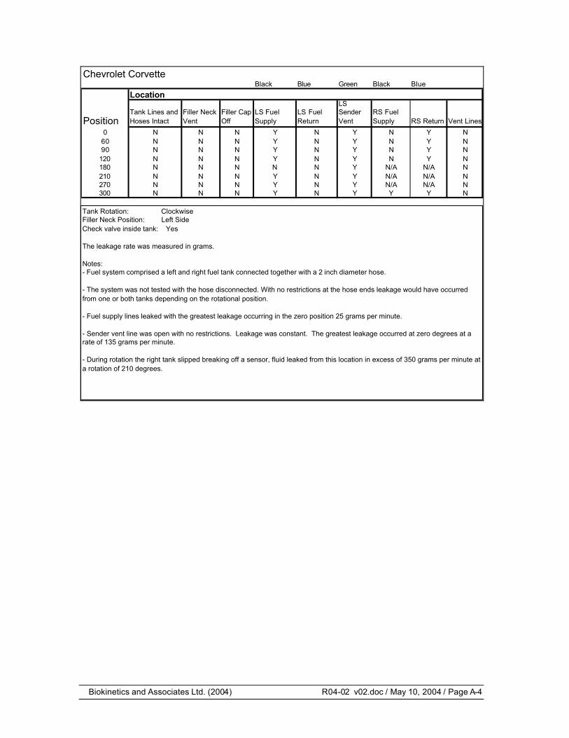
Chevrolet CorvetteBlack Blue Green Black Blue
Location
Position Tank Lines and Hoses Intact
Filler Neck Vent
Filler Cap Off
LS Fuel Supply
LS Fuel Return
LS Sender Vent
RS Fuel Supply RS Return Vent Lines
0 N N N Y N Y N Y N60 N N N Y N Y N Y N90 N N N Y N Y N Y N
120 N N N Y N Y N Y N180 N N N N N Y N/A N/A N210 N N N Y N Y N/A N/A N270 N N N Y N Y N/A N/A N300 N N N Y N Y Y Y N
Tank Rotation: ClockwiseFiller Neck Position: Left SideCheck valve inside tank: Yes
The leakage rate was measured in grams.
Notes:- Fuel system comprised a left and right fuel tank connected together with a 2 inch diameter hose.
- The system was not tested with the hose disconnected. With no restrictions at the hose ends leakage would have occurred from one or both tanks depending on the rotational position.
- Fuel supply lines leaked with the greatest leakage occurring in the zero position 25 grams per minute.
- Sender vent line was open with no restrictions. Leakage was constant. The greatest leakage occurred at zero degrees at a rate of 135 grams per minute.
- During rotation the right tank slipped breaking off a sensor, fluid leaked from this location in excess of 350 grams per minute at a rotation of 210 degrees.

Biokinetics and Associates Ltd. (2004) R04-02 v02.doc / May 10, 2004 / Page A-5
Chrysler Cirrus
Position Tank Lines and Hoses Intact
Filler Neck Vent
Filler Cap Off Fuel Supply Fuel Return Vent Lines
0 N N N N N/A N60 N N N N N/A N90 N N N N N/A N120 N N N N N/A N180 N N N N N/A N210 N N N N N/A N270 N N N N N/A N300 N N N N N/A N
Location
Tank Rotation: Counter ClockwiseFiller Neck Position: Left SideCheck valve inside tank: Yes
The leakage rate was measured in grams.
Notes:- Returnless system.
- There were no fuel leaks in any orientation,

Biokinetics and Associates Ltd. (2004) R04-02 v02.doc / May 10, 2004 / Page A-6
Dodge Neon
Position Tank Lines and Hoses Intact
Filler Neck Vent
Filler Cap Off Fuel Supply Fuel Return Vent Lines
0 N N N N N/A N60 N N N N N/A N90 N N N N N/A N
120 N N N N N/A N180 N N N N N/A N210 N N N N N/A N270 N N N N N/A N300 N N N N N/A N
Location
Tank Rotation: Counter ClockwiseFiller Neck Position: Right SideCheck valve inside tank: Yes
The leakage rate was measured in grams.
Notes:- Returnless system.
- There were no fuel leaks in any orientation,

Biokinetics and Associates Ltd. (2004) R04-02 v02.doc / May 10, 2004 / Page A-7
Ford Mustang
Position Tank Lines and Hoses Intact
Filler Neck Vent
Filler Cap Off Fuel Supply Fuel Return Vent Lines
0 N N N N N/A N60 N N N N N/A N90 N N N N N/A N
120 N N N N N/A N180 N N N N N/A N210 N N N N N/A N270 N N N N N/A N300 N N N N N/A N
Location
Tank Rotation: ClockwiseFiller Neck Position: Right SideCheck valve inside tank: Yes
The leakage rate was measured in grams.
Notes:- Initially the vent line on the tank leak 50 grams when the tank was filled to the top of the filler neck

Biokinetics and Associates Ltd. (2004) R04-02 v02.doc / May 10, 2004 / Page A-8
GMC Serria
Position Tank Lines and Hoses Intact
Filler Neck Vent
Filler Cap Off Fuel Supply Fuel Return Sender Vent Vent Lines
0 N N N N N N N60 N N N Y Y Y N90 N N N Y Y Y N120 N N N Y Y Y N180 N Y Y N Y N N210 N Y Y N N N N270 N Y Y N N N N300 N Y Y N N N N
Location
Tank Rotation: ClockwiseFiller Neck Position: Left SideCheck valve inside tank: No
The leakage rate was measured in grams.
Notes:- Rate of leakage with filler cap off was in excess of 1000 grams per min between 180 and 300 degrees rotation.
- The fuel supply and vent line leakage was minimal at less than 2 grams per minute.
- Fuel return leakage exceeded 1000 grams per min at 90 degrees rotation. At 180 degrees rotation, the flow rate dropped from 525 grams in the first minute to 93 grams per min in the fourth minute.

Biokinetics and Associates Ltd. (2004) R04-02 v02.doc / May 10, 2004 / Page A-9
Honda Odyssey
Position Tank Lines and Hoses Intact
Filler Neck Vent
Filler Cap Off Fuel Supply Fuel Return Vent Lines
0 N N N N N N60 N N N Y Y N90 N N N Y Y N
120 N N N Y Y N180 N N Y N Y N210 N N Y N Y N270 N N Y Y Y N300 N N N N N N
Location
Tank Rotation: Counter ClockwiseFiller Neck Position: Left SideCheck valve inside tank: Yes
The leakage rate was measured in grams.
Notes:- Rate of leakage with the filler cap off was greatest at 270 degrees at 465 grams per min. At 180 degrees rotation the flow reduced from 175 grams in the first min to 33 grams per min after three minutes.
- Fuel supply leaked between 0 and 120 degrees and again at 270 degrees at a flow rate was in excess of 200 grams per min.
- Fuel return leakage was constant from 0-270 degrees with the greatest flow rate of 488 grams per min at 210 degrees rotation..

Biokinetics and Associates Ltd. (2004) R04-02 v02.doc / May 10, 2004 / Page A-10
Jeep Cherokee
Position Tank Lines and Hoses Intact
Filler Neck Vent
Filler Cap Off Fuel Supply Fuel Return Vent Lines
0 N Y N N N/A N60 N N N N N/A N90 N N N N N/A N
120 N Y N N N/A N150 N Y Y N N/A N180 N Y N N N/A N210 N Y Y N N/A N270 N Y N N N/A N300 N Y Y N N/A N
Location
Tank Rotation: Counter ClockwiseFiller Neck Position: Left SideCheck valve inside tank: Yes
The leakage rate was measured in grams.
Notes:- Filler neck vent line leaked from filler neck end with the cap on at 150, 210, and 300 degrees of rotation.
- Filler neck vent line at the tank end leaked in excess of 1000 grams per min in all positions except for 60 and 90 degrees.
- Rate of leakage with filler cap off was greatest at 210 degrees rotation at a rate in excess of 550 grams per min.
Biokinetics and Associates Ltd. (2004) R04-02 v02.doc / May 10, 2004 / Page A-11
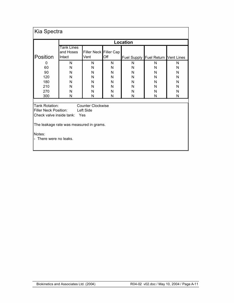
Kia Spectra
Position
Tank Lines and Hoses Intact
Filler Neck Vent
Filler Cap Off Fuel Supply Fuel Return Vent Lines
0 N N N N N N60 N N N N N N90 N N N N N N
120 N N N N N N180 N N N N N N210 N N N N N N270 N N N N N N300 N N N N N N
Location
Tank Rotation: Counter ClockwiseFiller Neck Position: Left SideCheck valve inside tank: Yes
The leakage rate was measured in grams.
Notes:- There were no leaks.

Biokinetics and Associates Ltd. (2004) R04-02 v02.doc / May 10, 2004 / Page A-12
Mazda MPV
Position Tank Lines and Hoses Intact
Filler Neck Vent
Filler Cap Off Fuel Supply Fuel Return Vent Lines
0 N Y N Y N/A N60 N Y N N N/A N90 N Y N N N/A N
120 N Y N N N/A N180 N Y Y 6 GRAMS N/A N210 N Y Y Y N/A N270 N Y Y Y N/A N300 N Y Y Y N/A N
Location
Tank Rotation: Counter ClockwiseFiller Neck Position: Left SideCheck valve inside tank: No
The leakage rate was measured in grams.
Notes:- Filler neck vent line at tank leaked constantly, flow rate was in excess of 400 grams per minute.
- Filler neck with cap off oriented at 80 degrees leaked at a rate of 81grams per min. At 270 degrees the flow rate increased to in excess of 600 grams per minute.
- Fuel supply line leakage was greatest at 210 degrees from 66 grams in the first minute to 23 grams per minute in the fourth minute. Leakage also occurred at 270 and 300 degrees with a minimal leakage of 6 grams in the 180 degree position.

Biokinetics and Associates Ltd. (2004) R04-02 v02.doc / May 10, 2004 / Page A-13
Mercury Grand Marquis
Position Tank Lines and Hoses Intact
Filler Neck Vent
Filler Cap Off Fuel Supply Fuel Return Vent Lines
0 N N N N N N60 N N N N Y N90 N N N N Y N
120 N N N N N N180 N N N N N N210 N N N N N N270 N N N N N N300 N N N N Y N
Location
Tank Rotation: Counter ClockwiseFiller Neck Position: Left SideCheck valve inside tank: Yes
The leakage rate was measured in grams.
Notes:- Leakage occurred at a rate of 35 grams per min in the 90 degrees position. The highest rate of leakage occurred at 300 degrees rotation at a rate of 69 grams per min.
- Leakage stopped between 100 and 280 degrees rotation.

Biokinetics and Associates Ltd. (2004) R04-02 v02.doc / May 10, 2004 / Page A-14
Plymouth Grand Voyageur
Position Tank Lines and Hoses Intact
Filler Neck Vent
Filler Cap Off Fuel Supply Fuel Return Vent Lines
0 N N N N N N60 N Y N N N N90 N Y N N N N
120 N Y N N N N180 N Y Y N N N210 N Y Y N N N270 N Y Y N N N300 N Y N N N N
Location
Tank Rotation: Counter ClockwiseFiller Neck Position: Left SideCheck valve inside tank: No
The leakage rate was measured in grams.
Notes:- Filler neck vent line at the tank end leaked in excess of 250 grams per min between 60 - 300 degrees rotation. Leakage occurred from filler neck end between 120 - 270 degrees at flow rate estimated to be above 150 grams per min.
- Rate of leakage with filler cap off was greatest at 180 degrees at a flow rate in excess of 1000 grams per min.

Biokinetics and Associates Ltd. (2004) R04-02 v02.doc / May 10, 2004 / Page A-15
Toyota Camry
Position Tank Lines and Hoses Intact
Filler Neck Vent
Filler Cap Off Fuel Supply Fuel Return Vent Lines
0 N Y N N N/A N60 N Y N Y N/A N90 N Y N Y N/A N
120 N Y N Y N/A N180 N Y Y Y N/A N210 N Y N Y N/A N270 N N N Y N/A N300 N N N Y N/A N
Location
Tank Rotation: ClockwiseFiller Neck Position: Left SideCheck valve inside tank: Yes
The leakage rate was measured in grams.
Notes:- Filler neck vent lines at the tank leaked in excess of 400 grams per minute in all positions indicated.
- Filler neck with the cap off leaked at a rate of 73 grams per min. at the 180 degree orientation.
- Fuel supply line leakage was greatest at 120 degrees from 160 grams in the first minute to 135 grams per minute after three minute. Leakage also occurred at 0 degrees during the filling process if the tank was filled to the top of the filler neck.

Biokinetics and Associates Ltd. (2004) R04-02 v02.doc / May 10, 2004 / Page A-16
Toyota Corolla
Position Tank Lines and Hoses Intact
Filler Neck Vent
Filler Cap Off Fuel Supply Fuel Return Vent Lines
0 N Y N N N/A N60 N Y N Y N/A N90 N Y N Y N/A N
120 N Y N Y N/A N180 N Y N Y N/A N210 N Y Y Y N/A N270 N Y N Y N/A N300 N Y N Y N/A N
Location
Tank Rotation: ClockwiseFiller Neck Position: Left SideCheck valve inside tank: Yes
The leakage rate was measured in grams.
Notes:- Filler Neck Vent leaked when disconnected from filler neck, draining fluid in filler neck.
- Fuel Supply leaked during over filling, as tank rotation approached 180 degrees flow rate increased exceeding 155 grams per min.
- Filler neck did not leak in the 180 position, however it did leaked as indicated at 120 degrees from horizontal where the filler neck is in an upside down position.
- Filler neck vent lines at the tank leaked 145 grams then stopped when all other lines were connected, movement of the tank caused further leakage spilling approx the 145 grams. with all lines disconnected the larger of the two vent lines at the filler neck opening leaked rapidly and constantly in excess of 450 grams per min.

Biokinetics and Associates Ltd. (2004) R04-02 v02.doc / May 10, 2004 / Page A-17
Toyota Prius
Position Tank Lines and Hoses Intact
Filler Neck Vent
Filler Cap Off Fuel Supply Fuel Return Vent Lines
0 N N N N N/A N60 N N N Y N/A N90 N N N Y N/A N
120 N N N Y N/A N180 N N Y Y N/A N210 N N Y Y N/A N270 N N N Y N/A N300 N N N Y N/A N
Location
Tank Rotation: ClockwiseFiller Neck Position: Right SideCheck valve inside tank: Yes
The leakage rate was measured in grams.
Notes:- Filler neck with cap off leaked at a rate of 287 grams per minute over a three minute period in the 180 degree orientation.
- Fuel supply line leakage was greatest at 120 degrees with 185 grams per minute. Leakage at 90 to 180 degrees was similar at 173 and 165 grams per minute. Leakage at 300 degrees was less than 5 grams per minute.

Biokinetics and Associates Ltd. (2004) R04-02 v02.doc / May 10, 2004 / Page A-18
VW Jetta
Position Tank Lines and Hoses Intact
Filler Neck Vent
Filler Cap Off Fuel Supply Fuel Return Vent Lines
0 N N N N N N60 N Y N N N N90 N Y N N N N
120 N Y N N N N180 N Y Y N N N210 N Y Y N N N270 N Y Y N N N300 N Y Y N N N
Location
Tank Rotation: ClockwiseFiller Neck Position: Right SideCheck valve inside tank: Yes
The leakage rate was measured in grams.
Notes:- Filler neck vent line at the tank end leaks at rate of 730 grams per min in the 90-270 degree positions. Rate of leakage in the 60 and 300 degrees was lower.
- Rate of leakage with filler cap off was greatest at 180 degrees, with a flow rate of 704 grams per min.

Biokinetics and Associates Ltd. (2004) R04-02 v02.doc / May 10, 2004 / Page A-19
Mercedes S430
Position Tank Lines and Hoses Intact
Filler Neck Vent
Filler Cap Off Fuel Supply Fuel Return Vent Lines
0 N N/A N Y Y N60 N N/A N Y Y N90 N N/A N Y Y N
120 N N/A N Y N N180 N N/A Y N N N210 N N/A Y Y N N270 N N/A Y Y N N300 N N/A Y Y N N
Location
Tank Rotation: ClockwiseFiller Neck Position: Right SideCheck valve inside tank: Yes
The leakage rate was measured in grams.
Notes:- Filler neck with cap off leaked 245 grams in the first minute, 38 grams in the second and zero in the third minute at 180 degrees. At 240 degrees rotation 4830 grams were measured over a 5 minute period. Excessive leakage also occurred at 270 and 300 degrees.
- Fuel supply leakage was not measured. With the fuel pump located out side of the tank, leakage at this point through the fuel strainer was estimated in excess of 1000 grams per minute.
- Fuel return line leakage was greatest at 0 degrees with 217 grams per minute leakage. Leakage also occurred at 60 and 90 degrees.

Biokinetics and Associates Ltd. (2004) R04-02 v02.doc / May 10, 2004 / Page A-20
Saturn SL
Position Tank Lines and Hoses Intact
Filler Neck Vent
Filler Cap Off Fuel Supply Fuel Return Vent Lines
0 N N N N N N60 N N N N N N90 N N N N N N
120 N N N N N N180 N Y Y N Y N210 N Y Y N Y N270 N Y Y N Y N300 N Y Y N N N
Location
Tank Rotation: Counter ClockwiseFiller Neck Position: Left SideCheck valve inside tank: Yes
The leakage rate was measured in grams.
Notes:- Rate of leakage with filler cap off was greatest at 270 degrees with 632 grams per min, at 300 degrees the flow reduced to 582 grams per min and at 180 degrees it reduced to 485 grams per min.
- Fuel return leakage was greatest at 210 degrees with a constant flow of 345 grams per min. Flow rates in other positions in which leakage occurred was constant.