Embed Size (px)
Citation preview

MAHARASHTRA STATE BOARD OF TECHNICAL EDUCATION (Autonomous)
(ISO/IEC - 27001 - 2005 Certified)
__________________________________________________________________________________________________
Page No: ____/ N
MODEL ANSWER SUMMER– 17 EXAMINATION Subject Title: Advanced Manufacturing Processes Subject Code:
Important Instructions to examiners: 1) The answers should be examined by key words and not as word-to-word as given in the model answer
scheme. 2) The model answer and the answer written by candidate may vary but the examiner may try to assess the
understanding level of the candidate. 3) The language errors such as grammatical, spelling errors should not be given more Importance (Not
applicable for subject English and Communication Skills. 4) While assessing figures, examiner may give credit for principal components indicated in the figure. The
figures drawn by candidate and model answer may vary. The examiner may give credit for any equivalent figure drawn.
5) Credits may be given step wise for numerical problems. In some cases, the assumed constant values may vary and there may be some difference in the candidate’s answers and model answer.
6) In case of some questions credit may be given by judgement on part of examiner of relevant answer based on candidate’s understanding.
7) For programming language papers, credit may be given to any other program based on equivalent concept.
Q. No.
Sub Q. N.
Answer Marking Scheme
1 a
(i)
Attempt any THREE of the following
Differentiate between AJM and WJM
Sr. No.
AJM WJM
1. Abrasive jet machining is process in which working
fluid is abrasives.
Water jet machining water acts as a working fluid
2. Rate of material removal depends on abrasive size
Rate of material removal depends on water pressure jet.
3. Used for brittle and hard material
Used for soft materials
4. Used where mass
production is required
Not suitable for mass production
5. Capital cost is low Capital cost is high
6. Process can be used for
intricate shape holes
Used for cutting thin nonmetallic
sheets
7. Suitable dust collection system is essential
WJM cleans work piece.
04 Marks for any four
differences
17527

MAHARASHTRA STATE BOARD OF TECHNICAL EDUCATION (Autonomous)
(ISO/IEC - 27001 - 2005 Certified)
__________________________________________________________________________________________________
Page No: ____/ N
(ii)
State advantages and applications of Broaching machines.
1) Broaching is faster than other machining operations
2) It enables higher rate of production with more accuracy & finish than other machining operations
3) It has longer tool life than other cutting tools. Tool cost per job is low
4) Both roughing & finishing operations are done by single tool
5) Interchangeable components can be produced at much faster rate in Broaching
6) Broaching operation does not require highly skilled operator
Applications of Broaching machine
i) Bearing Caps , Bearing bodies ii) Cylinder blocks ii) Cylinder Heads iii) turbine blades
iv) aircraft engine parts v) Crank cases vi) Toothed sprockets vii)
bushings
02Marks
for two advantages & 02 For
applications

MAHARASHTRA STATE BOARD OF TECHNICAL EDUCATION (Autonomous)
(ISO/IEC - 27001 - 2005 Certified)
__________________________________________________________________________________________________
Page No: ____/ N
MODEL ANSWER
SUMMER – 17 EXAMINATION
Subject Code:
Q. No.
Sub Q. N.
Answer Marking Scheme
(iii)
iv)
Define Gear Cutting. State gear manufacturing methods.
A gear is a rotating machine part having cut teeths , which mesh with
another toothed part to transmit torque. Gear is cut from round blank carrying teeth along its periphery. Gear cutting is specialized job . Gear cutting is any machining process for creating a gear. The most common gear-
cutting processes include hobbing, broaching, milling, and grinding. Such cutting operations may occur either after or instead of forming processes
such as forging, extruding, investment casting, or sand casting.
Gear manufacturing Methods:-
1) Casting-Gears are cast in metal moulds.
2) Rolling:- Gears are produced by Hot rolling or Cold rolling Process
3) Extrusion:- Gears are made from bar by extruding through forming die.
4) Stamping;- Small & thin gears are manufactured by stamping process
5) powder Metallurgy:- Small , highly accurate gears are produced through this process.
6) Machining ;- gears are produced by Gear shaping or Hobbing Machine
Explain the use of following codes in Part Programming
G95- Feed per revolution , G41-Tool compensation on left or right hand side of the part
M06-Automatic Tool Change , M98-Sub-programme call (Call subroutine)
2 marks for
definition and
2 marks for
manufacturing
methods
1 mark each for
correct ans
17527

MAHARASHTRA STATE BOARD OF TECHNICAL EDUCATION (Autonomous)
(ISO/IEC - 27001 - 2005 Certified)
__________________________________________________________________________________________________
Page No: ____/ N
Q1
B)
Q1
B)
(i)
(ii)
Attempt any ONE of the following
Draw neat labeled sketch of Center less grinding. Explain its working
In this process the job/work piece is supported between grinding wheel,
regulating wheel & work rest blade. Center less grinding operation is performed by grinding wheel only while regulating wheel provides support to
work piece while it is pushed away by grinding pressure of grinding wheel. The direction of rotation both wheels are the same. External & Internal grinding can be done on center less grinding machine. The common methods
used for feeding the work are
i) Through Feed- In this , the workpiece is supported ,revolved & feed axially
by regulating wheel .Axis of regulating wheel is inclined by 2 to 10 degree with the vertical. ii) Infeed :- Thr regulating wheel is drawn away to
accommodate the workpiece on blade of work rest ,then regulating wheel is pushed in to press against the work.
iii) End feed. :- In this method grinding wheel & Regulating wheel is dressed to contain the required shape. The workpiece is fed longitudinally from the sides of wheels
Define:-
1) Maintenance Manual:- Maintenance manual comes with purchased
machine. It gives information about the preventive maintenance to be done with respect to time scale of service period of machine tool. The maintenance manual is prepared based on previous experience & feedback received by
manufacturer. This manual helps for systematic maintenance of machine tool without trial & error method. It gives standards to be used e.g Oil grade ,
spare parts etc. Safety procedures to be followed.
2) Maintenance records, state the types of maintenance.
Maintenance records are the various documents of maintenance activities carried out by staff of the maintenance section. These documents are used for improvements as well as to get the history of maintenance of a particular machine or equipment. The maintenance records include following reports.
3 marks for
sketch & 3
marks for explan
ation
3 marks for
each point

MAHARASHTRA STATE BOARD OF TECHNICAL EDUCATION (Autonomous)
(ISO/IEC - 27001 - 2005 Certified)
__________________________________________________________________________________________________
Page No: ____/ N
Q 2
a)
1.Machine history card.
2.Preventive maintenance chart.
3. Break down Report.
By using these previous record and its analysis it is easy for fast decision making when faults occur in the machine.
Types of maintenance are as following
Planned maintenance:- Preventive maintenance , Predictive maintenance ,
Routine maintenance, corrective maintenance
Unplanned Maintenance:- Breakdown maintenance , Opportunistic
maintenance
Attempt any FOUR of the following
Explain the concept of :-
(i) Repair cycle analysis :- To ensure that entire repair work is carried out in a planned Maintenance system ,The repair cycle is followed, which consists of four stages as following
A) Inspection and adjustment –Visual inspection is done of bearings , clutches, sliding parts , filters are cleaned.
B) Small repairs:- Sub-assemblies are dismantled & restored for efficient
operations.
C) Medium Repairs:- This stage involves checking the equipment as per
prescribed standards .
D) Complete overhaul :- This is planned maintenance as per reports,
undertaken after fairly long period of operation.
(ii) Repair complexity
Repair Complexity is defined as the extent of complexity of machine tool considered for the maintenance work which is represented by a comparative index number. This number is called as repair complexity number .If the repair complexity number is high, then repair cycle of the machine is longer because it consists high number
of maintenance activities. Repair complexity number is useful to decide the number of staff required for maintenance, to decide inventory of spares required for maintenance. To decide the repair cycle of the particular machine. To find out the number of critical maintenance points of the machine. T o forecast the maintenance cost of the machine or plant. Also repair complexity decides the time interval of repair cycle. On the basis of repair complexity number maintenance schedule is prepared for the machine or plant. For higher number long schedule is prepared while for small complexity number short schedule is needed. For example repair complexity number of various machines are given as follows.
2 marks
each for (i) & (ii)
MAHARASHTRA STATE BOARD OF TECHNICAL EDUCATION (Autonomous)
(ISO/IEC - 27001 - 2005 Certified)
__________________________________________________________________________________________________
Page No: ____/ N
b)
c)
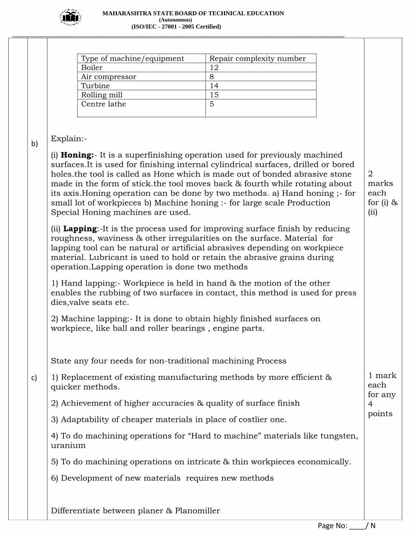
Type of machine/equipment Repair complexity number
Boiler 12
Air compressor 8
Turbine 14
Rolling mill 15
Centre lathe
5
Explain:-
(i) Honing:- It is a superfinishing operation used for previously machined surfaces.It is used for finishing internal cylindrical surfaces, drilled or bored
holes.the tool is called as Hone which is made out of bonded abrasive stone made in the form of stick.the tool moves back & fourth while rotating about its axis.Honing operation can be done by two methods. a) Hand honing ;- for
small lot of workpieces b) Machine honing :- for large scale Production Special Honing machines are used.
(ii) Lapping:-It is the process used for improving surface finish by reducing roughness, waviness & other irregularities on the surface. Material for
lapping tool can be natural or artificial abrasives depending on workpiece material. Lubricant is used to hold or retain the abrasive grains during operation.Lapping operation is done two methods
1) Hand lapping:- Workpiece is held in hand & the motion of the other
enables the rubbing of two surfaces in contact, this method is used for press dies,valve seats etc.
2) Machine lapping:- It is done to obtain highly finished surfaces on workpiece, like ball and roller bearings , engine parts.
State any four needs for non-traditional machining Process
1) Replacement of existing manufacturing methods by more efficient &
quicker methods.
2) Achievement of higher accuracies & quality of surface finish
3) Adaptability of cheaper materials in place of costlier one.
4) To do machining operations for “Hard to machine” materials like tungsten, uranium
5) To do machining operations on intricate & thin workpieces economically.
6) Development of new materials requires new methods
Differentiate between planer & Planomiller
2 marks
each for (i) & (ii)
1 mark each for any
4 points

MAHARASHTRA STATE BOARD OF TECHNICAL EDUCATION (Autonomous)
(ISO/IEC - 27001 - 2005 Certified)
__________________________________________________________________________________________________
Page No: ____/ N
d)
e)
PLANER PLANOMILLER
1) Single point cutting tool is used
for cutting the job
Multi point cutting tool is used for
cutting the job
2) It can cut the workpiece during forward stroke of table only
It can cut the workpiece during both, forward and return stroke of
table
3) Different Tools are required as per the shape of job.
Single cutter can be used for nos. of jobs.
4) Process is slow 4) Process is faster
5) Highly skilled operator is required
5) Semiskilled operator can be operate this machines.
6) Tool is stationary 6) Tool is rotating
State meaning of absolute and incremental co-ordinate system
Absolute System:-In this system , the positions are indicated from fixed zero point of reference point.
As shown in figure all tool positions are shown with reference to a fixed zero point.
Incremental System :- In this System, the tool positions are indicated with
reference to a previously known location. As shown in figure all tool positions
are shown with reference to a previous dimension point.
1 mark each
for any 4
points
2 mark each
for correct
meaning

MAHARASHTRA STATE BOARD OF TECHNICAL EDUCATION (Autonomous)
(ISO/IEC - 27001 - 2005 Certified)
__________________________________________________________________________________________________
Page No: ____/ N
f)
Explain LBM with suitable Sketch
Laser(amplification of light by stimulated emission of radiation ) beam machining set up consists of a stiumulating light source and a laser rod. The light radiated from the flash lamp is focused on to the laser rod from where it is reflected and accelerated in the path. This light is emitted in the form of divergent beam. A lens is incorporated in the path of this beam of light which converges and focuses the light beam on to the workpiece to be machined. This concentration of laser beam on the work piece melts the work material & vapourises it.
Sketch 2
marks & Explan
ation 2 marks
MAHARASHTRA STATE BOARD OF TECHNICAL EDUCATION (Autonomous)
(ISO/IEC - 27001 - 2005 Certified)
__________________________________________________________________________________________________
Page No: ____/ N
Q3
a)
b)
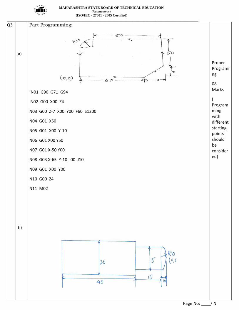
Part Programming:
`N01 G90 G71 G94
N02 G00 X00 Z4
N03 G00 Z-7 X00 Y00 F60 S1200
N04 G01 X50
N05 G01 X00 Y-10
N06 G01 X00 Y50
N07 G01 X-50 Y00
N08 G03 X-65 Y-10 I00 J10
N09 G01 X00 Y00
N10 G00 Z4
N11 M02
Proper Programing
08 Marks
( Programming with different starting points should be considered)

MAHARASHTRA STATE BOARD OF TECHNICAL EDUCATION (Autonomous)
(ISO/IEC - 27001 - 2005 Certified)
__________________________________________________________________________________________________
Page No: ____/ N
c)
Assuming S=2500 rpm and Feed= 30 mm/min
N01 G21 G90 G92 X5 Z5
N02 M03 S2500
N03 G00 X00 Z2
N04 G01 X10 Z-65 F30
N05 G00 X00 Z2
N06 G01 X7.5 Z-25
N07 G00 X00 Z2
N08 G02 X7.5 Z-10 R10 F30
N09 G01 X00 Z2
N10 M05 M30
Steps for Compound Indexing;
1) Factories the number of divisions required.
2) Factories the standard number 40
3) Select for trial any two circles on the same plate and on its same side. Factories their
difference
4) Factories the number of holes of one circle.
5) Factories the number of holes of the other circle.
After obtaining these factors place them as follows;
Factors of divisions required X Factors of difference of hole circles
Factors of 40 X Factors of First Circle X Factors of Second Circle
Example: Compound Indexing for 51 divisions
Required movement = 40/51
Let us try circles of 17 and 18 holes
The first expression = 3X17X1 =1/240
10X4X17X3X6
We get unity in numerator, so circles selected are correct.
240/17 – 240/18 Or 240/18 – 240/17
proper Programing
08 Marks
( Programming with different starting points should be considered)
04 Marks for Steps
04 Marks for
Example
MAHARASHTRA STATE BOARD OF TECHNICAL EDUCATION (Autonomous)
(ISO/IEC - 27001 - 2005 Certified)
__________________________________________________________________________________________________
Page No: ____/ N
Q4
a)
i)
14 2/17 -13 6/18 Or 13 6/18 – 14 2/17
By taking out 14 as common, the above expression will be reduced as;
2/17 + 12/18 Or -12/18-2/17
Similar signs show that both the movements will be in the same direction. By adopting the first result we get the required movement.
( Similar type of Examples can be Considered )
Select Non Traditional Machining Processes with Justification:
1. Machining Profile Of Glass:
Ultrasonic Machining :- USM is mechanical material removal process or an
abrasive process used to erode holes or cavities on hard or brittle work piece by using shaped tools, high frequency mechanical motion and an abrasive
slurry. USM offers a solution to the expanding need for machining brittle materials such as single crystals, glasses and polycrystalline ceramics, and increasing complex operations to provide intricate shapes and work piece
profiles. It is therefore used extensively in machining hard and brittle materials that are difficult to machine by traditional manufacturing
processes. The hard particles in slurry are accelerated toward the surface of the work piece by a tool oscillating at a frequency up to 100 KHz - through repeated abrasions, the tool machines a cavity of a cross section identical to
its own.
Justification:-
1. USM process is a non-thermal, non-chemical, creates no changes in the microstructures, chemical or physical properties of the work piece and offers virtually stress free machined surfaces.
2. Especially suitable for machining of brittle materials
3. Machined parts by USM possess better surface finish and higher structural integrity.
4.USM does not produce thermal, electrical and chemical abnormal surface.
OR (Abrasive water jet cutting can be considered with Justification)
Abrasive water jet cutting
Abrasive water jet cutting is an extended version of water jet cutting; in which the water jet contains abrasive particles such as silicon carbide or aluminum oxide in order to increase the material removal rate above that of water jet machining. Almost any type of material ranging from hard brittle materials such as ceramics, metals and glass to extremely soft materials such as foam and rubbers can be cut by abrasive water jet cutting.
2. Cutting Internal Thread in Hard Material:-
04 Marks for all correct Answers with Justification

MAHARASHTRA STATE BOARD OF TECHNICAL EDUCATION (Autonomous)
(ISO/IEC - 27001 - 2005 Certified)
__________________________________________________________________________________________________
Page No: ____/ N
1. EDM :- Electro Discharge Machining-
Electro Discharge Machining (EDM) is an electro-thermal non-traditional machining process, where electrical energy is used to generate electrical spark and material removal mainly occurs due to thermal energy of the spark. EDM is mainly used to machine difficult-to-machine materials and high strength temperature resistant alloys. EDM can be used to machine difficult geometries in small batches or even on job-shop basis. Work material to be machined by EDM has to be electrically conductive. In EDM, the spark occurs between the two nearest point on the tool and work piece. Thus machining may occur on the side surface as well leading to overcut and taper cut as depicted.
Justification:-
1. Process is used for Hard Materials.
2. Surface finish is Good.
3. Complicated thread profiles can be cut.
OR (ECM can be considered with Justification)
Electrochemical Machining (ECM) is a non-traditional machining (NTM) process belonging to Electrochemical category. ECM is opposite of electrochemical or galvanic coating or deposition process. Thus ECM can be thought of a controlled anodic dissolution at atomic level of the work piece that is electrically conductive by a shaped tool due to flow of high current at relatively low potential difference through an electrolyte which is quite often water based neutral salt solution.
3. Cutting Of Hot Extrusion Components:-
Electron Beam Machining (EBM) and Laser Beam Machining (LBM) are thermal processes considering the mechanisms of material removal. However electrical energy is used to generate high-energy electrons in case of Electron Beam Machining (EBM) and high-energy coherent photons in case of Laser Beam Machining (LBM). In case of oxyacetylene flame or welding arc, the characteristic length is in mm to tens of mm and the power density is typically low. Electron Beam may have a characteristic length of tens of microns to mm depending on degree of focusing of the beam
Justification :-
1. No physical tool is required.
2. Surface finish after cutting is as good as finish.
3. Complex cutting is possible.
Sketch Milling Cutters for the following.

MAHARASHTRA STATE BOARD OF TECHNICAL EDUCATION (Autonomous)
(ISO/IEC - 27001 - 2005 Certified)
__________________________________________________________________________________________________
Page No: ____/ N
ii)
iii)
1) Side Milling
Any One Fig.
2) Facing
3. Plain Milling
Specification of Grinding Wheels with Suitable example:-
Grinding wheels are specified as:-
It consists of Six symbols representing properties of the grinding wheel.
1. Type of Abrasives
2. Grain size
3. grade
04 Marks for all correct Answers
02 Marks for explanation 02 Marks for Example

MAHARASHTRA STATE BOARD OF TECHNICAL EDUCATION (Autonomous)
(ISO/IEC - 27001 - 2005 Certified)
__________________________________________________________________________________________________
Page No: ____/ N
iv)
4. structure
5. Type of Bond
6. Manufacturers symbol for reference ( optional)
Apart from the above information , in order to specify grinding wheel
completely, the size, ie Dia, and width or thickness and the dia of Bore are also required to be specify.
Example : 250 X 25 X 32 W A 46 L 4 V 17
Wheel Dia= 250mm
Thickness of wheel= 25 mm
Bore dia=32mm
W = Manufacturers Prefix to Abrasive Here it is White
A= Abrasive
46= Grain Size
L= Medium Grade
4= Dense Structure
V= Vitrified Bond
17= Bond type
Terms In CNC Machines:-
1) Dry Run:- It is the trial run without actual running of CNC machine for checking correct shape of the component. It shows correctness of the steps
given in the program. It give idea about the tool impact collision with the chuck and other machine parts due to incorrect program.
2) Jog Mode:- This mode of machine is useful for initial setting of machine tool before doing manufacturing of component. Jog mode means warm up of
machines slides to check for initial settings. In this mode machine axes are moved by using direction keys provided on the control panel of the CNC
machine. With this jog mode operator can set the tool /work piece at required position with reference to the location of machine table or chuck.
3) Block By Block execution:- The CNC program consists of program blocks which are numbered as N10, N20 etc. In CNC single block mode only one block of CNC will be executed, in CNC execution of program can be done
completely or Block By Block.
02
02

MAHARASHTRA STATE BOARD OF TECHNICAL EDUCATION (Autonomous)
(ISO/IEC - 27001 - 2005 Certified)
__________________________________________________________________________________________________
Page No: ____/ N
b)
i)
ii)
Straddle Milling Operation For Hexagonal Bolt:-
This is similar to the side milling operation. Two side milling cutters are mounted on the same arbor
Distance between them is so adjusted with the help of spacing collars such that both sides of the work piece can be milled simultaneously. Hexagonal bolt can be produced by this operation by rotating the work-piece only two times as this operation produces two parallel faces of bolt simultaneously.
Fig- Straddle Milling Operation
Sr. No Capstan lathe Turret lathe
1. It is a light duty machine It is a heavy duty machine
2. The turret head is mounted on the ram
and the ram is mounted on the saddle.
The turret head is directly mounted on the saddle
and the saddle slides over the bed ways
3. The saddle will not be moved during
machining
The saddle is moved along with the turret head
during machining
4. The lengthwise movement of turret is
less The lengthwise movement of turret is more
5. Short work pieces only can be
machined. Long work pieces can be machined
6. It is easy to move the turret head as it
slides over the ram
It is difficult to move the turret head along with
saddle
7. The turret head cannot be moved
crosswise
The turret head can be moved crosswise in some
turret lathes
8. As the construction of lathe is not
rigid, heavy cut cannot be given
As the construction of lathe is rigid, heavy cut
can be given
9. It is used for machining work pieces
up to 60mm diameter
It is used for machining work pieces up to
200mm diameter
10. Collate is used to hold the work piece Jaw chuck is used to hold the work piece
03
03
01 for each any six

MAHARASHTRA STATE BOARD OF TECHNICAL EDUCATION (Autonomous)
(ISO/IEC - 27001 - 2005 Certified)
__________________________________________________________________________________________________
Page No: ____/ N
Q5
a)
b)
Maintenance Practices for Bearings: (i) Never spin the bearing with compressed air.
(ii) Do not try to disassemble the bearing.
(iii) Avoid direct fire or fumes contact with bearing.
(iv) Do not hit the bearing with metal part/use bearing pullers while assembling or
dismantling.
(v) Store the bearing away from moisture.
(vi) Check the clearance between bearing cap and bearing using plastic gauge before assembly.
(vii) Do not run the bearing over its specified speed.
(viii) Do not throw away broken bearing, it may help you to know type of failure for corrective
actions.
[2] Maintenance Practices for Chains: (i) Use covers on chains to avoid entry of foreign material.
(ii) Check alignment.
(iii) Inspect chain flexibility.
(iv) If amount of stretch is greater than 3% of its original length, then single pitch rollers
should be changed.
(v) Lubricate chain properly and periodically.
(vi) Check for any physical damage of chain/s.
PAM :- In plasma arc machining the gases are ionized by placing an arc across the path of gas
flow. The gas molecules get dissociated causing large amount of thermal energy to be liberated.
This generates temperatures of the order of 165000C , which are than utilized in removing metal
by melting and vaporization.
WEDM :- The basic mechanism of metal removal in WEDM is identical to that in die sinking type
EDM. Instead of moving electrode, the electrode in this process is a moving wire of CU or brass.
A vertically oriented wire is fed into the work piece continuously travelling from a supply spool to
take a spool, so that it is continuously renewed , since it will get worn out during the process.
02
02
02
02

MAHARASHTRA STATE BOARD OF TECHNICAL EDUCATION (Autonomous)
(ISO/IEC - 27001 - 2005 Certified)
__________________________________________________________________________________________________
Page No: ____/ N
c)
d)
e)
Buffing :- buffing is a polishing operation in which the work piece is brought in contact with
revolving cloth buffing wheel, that usually has been charged with the fine abrasive. The polishing
action in buffing is very closely related to lapping.
Burnishing :- Burnishing operation is the process of getting a smooth and shiny surface by contact
and rubbing of the surface against the walls of hard tool. It is finishing and strengthening process.
Burnishing is basically a cold surface plastic deformation process.
Gang Milling:-
When two or more milling cutters are mounted on an arbor so that each cutter will produce its own
distinctive surface as work piece is fed to it, the operation is called “ gang milling”
02
02
02
02

MAHARASHTRA STATE BOARD OF TECHNICAL EDUCATION (Autonomous)
(ISO/IEC - 27001 - 2005 Certified)
__________________________________________________________________________________________________
Page No: ____/ N
f)
Maintenance Practices for Gears: 1) Select the proper gear.
2) Select proper raw material for manufacturing of gear.
3) Do the balancing of gear properly.
4) Do the proper alignment of gear on shaft and key.
5) Check the alignment of gear with its meshing gear.
6) Check the lubrication and change the oil on specified intervals.
7) Minor repairs like burr or imperfections can be cleared by using a fine oil stone or file.
8) If major repair is required remove the gear from assembly, repair it and assemble.
Maintenance Practices for machine belts:
1) The belt is free from damages.
2) It must be properly aligned.
3) It should be properly assembled to the other mating parts
4) Check tension in the belt
02
02
02
02

MAHARASHTRA STATE BOARD OF TECHNICAL EDUCATION (Autonomous)
(ISO/IEC - 27001 - 2005 Certified)
__________________________________________________________________________________________________
Page No: ____/ N
6
a)
b)
c)
i)
When internal surface of a hollow part is turned, that is, single point tool is used for
enlarging a hole, the operation is called as boring.
Types of boring:-
Counter boring
Counter sinking
Spot facing
Slot milling :-
Rectangular, T and dovetail slots are milled on vertical spindlie machines by means of
suitable shank type milling cutters. Rectangular slots can also be machined on horizontal
machine.
Key ways can be machined with special cutters
Splines may be milled on horizontal spindle machines by using single / double angle
cutters.
Open Loop control:-
In open loop system the command signal from the MCU is given to the servo motor. The
motor is driven a precise angular rotation for every pulse issued by CLU. So, the response
of motor is incremental step of is common. This will result in a corresponding linear
movement of the lead screw and hence of the machine slide.
02
02
02
02
01
01

MAHARASHTRA STATE BOARD OF TECHNICAL EDUCATION (Autonomous)
(ISO/IEC - 27001 - 2005 Certified)
__________________________________________________________________________________________________
Page No: ____/ N
ii)
d)
Closed loop control in CNC
The name indicates that the closed loop control system has a loop that is closed as shown in fig. A
feedback device is used for this purpose. This makes the design of closed loop a little complicated
and expensive. But a very high degree of accuracy is achieved in the movement of slide.
This system is similar to open loop control system. But it consists of two additional devices in the
form of feedback transducer and a comparator as shown in Fig.
The transducer feedbacks the actual slide displacement to the comparator. The comparator
compares the actually achieved slide movement with command signal. If there is any error then it
is feedback to the MCU.
The MCU then sends the corrective commands to the drive unit and the cycle repeats until
there is no error signal from the comparator
Sketches of boring tools:- any two
(1) Light Boring Tools (2) Forged Boring Tools (4) Double Ended Boring Tool
(3) Boring Bar (6) Counter Boring Tool (5) Multiple Edged Boring Tool
01
01
02 for each sketch
Any two

MAHARASHTRA STATE BOARD OF TECHNICAL EDUCATION (Autonomous)
(ISO/IEC - 27001 - 2005 Certified)
__________________________________________________________________________________________________
Page No: ____/ N
e)
f)
Compare Pull broach and push broach
Pull broach Push broach
Broach is pulled through work piece Broach is pushed through work piece
Broach is longer in length Broach is comparatively shorter in length
Length of surface to be machined is long Length of surface to be machined is short
No. of teeth’s are more No. of teeth’s are less
Broach is in tension Broach is in compression
Various aspects of safety for grinding are
1) Operator should always use safety devices such as goggles & aprons to protect his eyes
and body from the flying abrasive particles and dust.
2) Wheel should be checked for the damage in the transit, cracks and other tests. Sound
wheel when tapped lightly sound clear while crack wheel will not ring this is called
ring test on grinding wheel.
3) Wheels not in used should be stored in dry place & placed on their edges in racks.
4) Wheel should be correctly mounted in the spindle and enclosed by the guards
5) Wheel speed which is dependent on bursting strength, grit size, bond, structure etc and is
usually specified by the manufacturers should not be exceeded in order to avoid the accidents.
6) Do not tighten the flange bolts excessively in order to avoid the cracking of the wheel.
7) During wet grinding the wheel should not be partly immersed in order to avoid out of
balance of the wheel.
8) Ensure adequate power supply during grinding operation in adequate power may cause
out of balance of the wheel
01 for
each any four
01 for each
any four