Embed Size (px)
Citation preview
www.summitracing.com SUMMIT RACING EQUIPMENT TECH 1
Summit RacingStreet & Strip Digital CD Ignition
Part No. SUM-850610
Parts Included:1 - Ignition Control4 - Mounting Screws
WARNING: During installation, disconnect the battery cables. When disconnecting the battery always remove the Negative cable first and install it last.
Note: Solid Core spark plug wires cannot be used with the Summit CDI Control.Note: The Summit CD Ignition cannot be used with distributorless ignition systems (DIS).
GENERAL INFORMATIONBATTERYThe Summit Racing Street & Strip Digital CD Ignition Control will operate on any negative ground, 12 volt electrical system with a distributor. It can be used with 16 volt batteries and can withstand a momentary 24 volts in case of jump starts. The Ignition will deliver full voltage with a supply of 9 - 18 volts and will operate with a supply voltage as low as 7 volts.
COILSThis Ignition can be used with most stock coils and aftermarket coils designed to replace the stock coils. If you have any questions concerning coils, contact our Tech Department at (330) 630-0240.
TACHOMETERSThis Ignition features a Tach Output wire that provides a trigger signal for tachometers, a shift light or other add-on rpm activated devices. The Tach Output produces a 12 volt square wave signal with a 24% duty cycle. Some vehicles with factory tachometers may require a Tach Adapter to operate with the ignition. If your GM vehicle has an inline filter it may cause the tach to drop to zero on acceleration. If this occurs, bypass the filter.
FOREIGN VEHICLESDue to the fuel injection systems, some foreign vehicles may require a special Tach/Fuel Injection Adapter with this Summit Ignition. See page 9 for wiring and Tach Adapter information.Note: Vehicles originally equipped with a CD ignition control cannot use this Summit Ignition.
SPARK PLUGS AND WIRESSpark plug wires are very important to the operation of your ignition system. A good quality, helically wound wire and proper routing are required to get the best performance from your ignition, such as Summit Racing Street & Strip Ignition Wire.
Note: Solid Core spark plug wires cannot be used with this Summit Ignition.
Spark Plugs: Choosing the correct spark plug design and heat range is important when trying to get the best performance possible. It is recommended to follow the engine builder or manufacturer's specification for spark plugs. With that, you can then experiment with the plug gap to obtain the best performance. The gap of the plugs can be opened in 0.005" increments, then tested until the best performance is obtained.
MISCELLANEOUS INFORMATIONSealing: Do not attempt to seal the ignition. All of the circuits of this Summit Ignition receive a thick conformal coating for resistance against moisture. Rubber plugs are supplied to protect the rpm dials.
Welding: If you are welding on your vehicle, to avoid the chance of damage, always disconnect both Heavy Power cables of the ignition (you should also disconnect the tach ground wire).
1 - Screwdriver2 - Wiring Harnesses
1 - Misc. Connectors/Wiring
2 SUMMIT RACING EQUIPMENT TECH (330) 630-0240
MOUNTINGThis Summit Ignition can be mounted in most positions, except directly upside down (if upside down, moisture or water cannot escape). It can be mounted in the engine compartment as long as it is away from direct engine heat sources. It is not recommended to mount the unit in an enclosed area such as the glove box.
When you find a suitable location to mount the unit, make sure the wires of the ignition reach their connections. Hold the Ignition in place and mark the location of the mounting holes. Use an 1/8" drill bit to drill the holes. Use the supplied self tapping screws to mount the box.
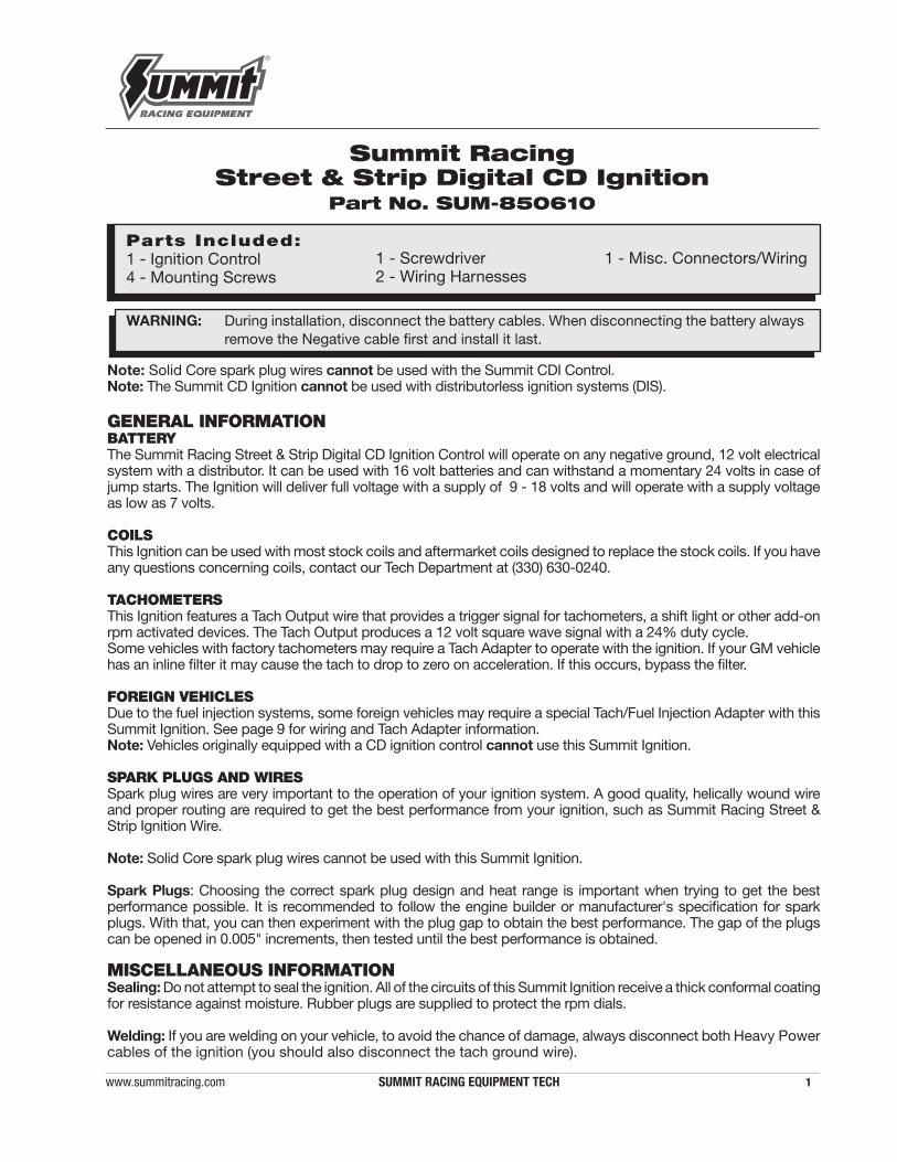
CYLINDER SELECTThe Rev Limiter that is built into the ignition is programmed for operation on an 8-cylinder engine. If you are installing one of these units on a 4 or 6-cylinder even-fire engine, the cylinder count must be selected. This is easily achieved through the cylinder select wire loops on the side of the ignition. To program the unit cut the loops as shown in Figure 1.
LEDThere is a diagnostic LED next to the rpm dials. The LED will blink with each trigger signal. It will appear On when the engine is running. If the input voltage drops below 9 volts it will flash at idle speed.
WIRINGWire Length: All of the wires of the ignition may be shortened as long as quality connectors are used or soldered in place. To lengthen the wires, use one size bigger gauge wire (10 gauge for the power leads and 16 gauge for the other wires) with the proper connections.
Grounds: A poor ground connection can cause many frustrating problems. When a wire is specified to go to ground, it should be connected to the battery negative terminal, engine block or chassis. There should always be a ground strap between the engine and the chassis. Always securely connect the ground wire to a clean, paint free metal surface.
These are the two heavy gauge wires (14 gauge) and are responsible for getting direct battery voltage to the Ignition.
This wire connects directly to the battery positive (+) terminal or to a positive battery junction or the positive side of the starter solenoid.Note: Never connect to the alternator.
This wire connects to a good ground, either at the battery negative (-) terminal or to the engine.
Connects to a switched 12 volt source. Such as the ignition key or switch.
Connects to the positive (+) terminal of the coil. This is the only wire that makes electrical contact with the coil positive terminal.
Connects to the negative (-) terminal of the coil. This is the only wire that makes electrical contact with the coil negative terminal.
Tach output wire. Connect to the tachometer or other rpm device.
There are two circuits that can be used to trigger the Summit Ignition; a Points circuit (White wire) and a Magnetic Pickup circuit (Violet and Green wires). The two circuits will never be used together.
This wire is used to connect to the points or electronic ignition amplifier output .
These wires are routed together in one harness to form the Magnetic Pickup connector. The connector plugs directly into a distributor with a magnetic pickup. It will also connect to factory magnetic pickups or other aftermarket pickups. The Violet wire is positive (+) and the Green is negative (-). When these wires are used, the White wire is not.
POWER LEADS
HEAVY RED
HEAVY BLACK
RED
ORANGE
BLACK
GRAY
TRIGGER WIRES
WHITE
VIOLET AND GREEN (Magnetic Pickup Connector)
WIRE FUNCTIONS
Figure 1 Selecting the number of Cylinders.
CYLINDERSELECT LOOPS
www.summitracing.com SUMMIT RACING EQUIPMENT TECH 3
Ballast Resistor: If your vehicle has a ballast resistor inline with the coil wiring, it is recommended to bypass it.
ROUTING WIRESWires should be routed away from direct heat sources such as exhaust manifolds and headers and any sharp edges. The trigger wires should be routed separate from the other wires and spark plug wires. It is best if they are routed along a ground plane such as the block or firewall, which creates an electrical shield. The magnetic pickup wires should always be routed separately and should be twisted together to help reduce extraneous interference.
REV LIMITERThis Summit Ignition features an adjustable rev limiter. This feature will protect your engine from overrev damge in the event of driveline failure or a missed gear. The rev limit is adjustable from 2,000 - 9,900 rpm in 100 rpm increments (Figure 3).
PRESTART CHECK LIST• The only wires connected to the coil terminals are: Orange to coil positive,
and Black to coil negative.• The small Red wire of the Ignition is connected to a switched 12 volt source.• If running a 4- or 6-cylinder engine the cylinder select must be modified.• The power leads are connected directly to the battery positive and negative
terminals.• The battery is connected and fully charged if not using an alternator.• The engine is equipped with at least one ground strap to the chassis.
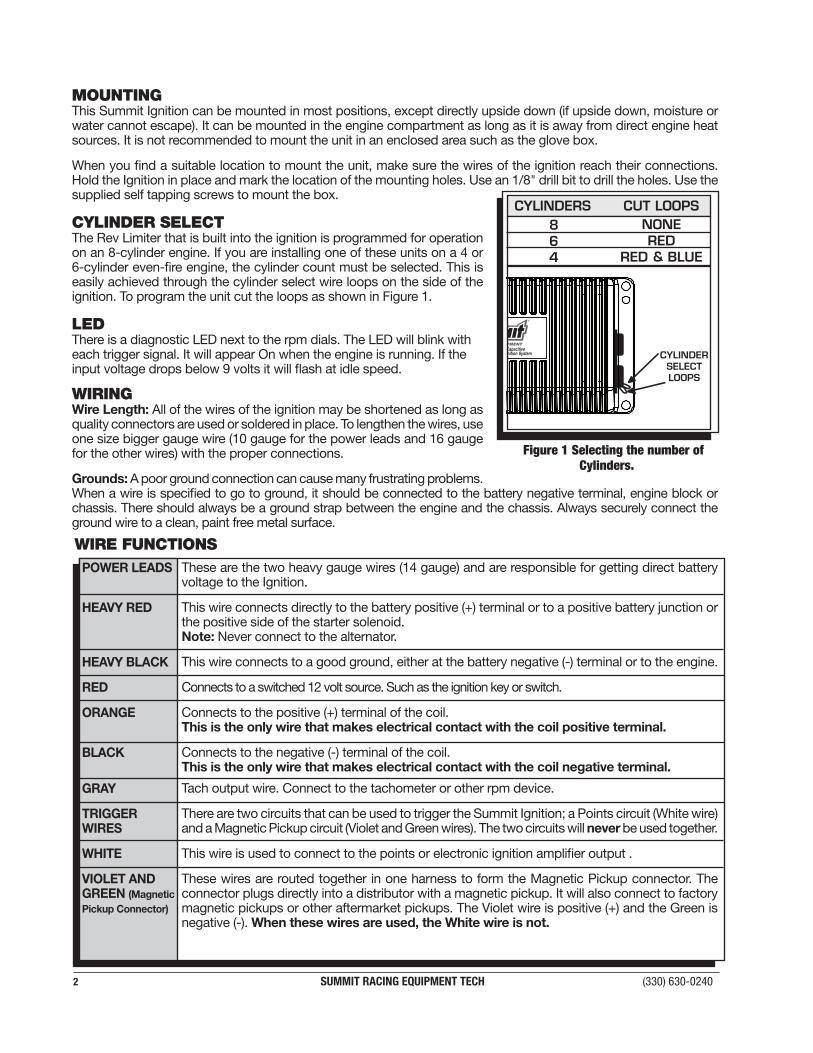
The chart in Figure 2 shows the polarity of other common magnetic pickups.
Figure 2 Common Mag Pickup Wires.
Common Mag Pickup Wires Colors Mag+ Mag-SUMMIT Distributor Org/Blk Vio/BlkFord Orange VioletAccel 46/48000 Series Org/Blk Vio/BlkAccel 51/61000 Series Red BlackChrysler Org/Wht BlackMallory Org/Blk Vio/BlkSummit CDI Violet Green
COILORANGE
BLACK
SMALL RED
GRAYTO TACH
MAGNETIC PICKUP(NOT USED)
WHITE
SUMMIT SYSTEMS Installing to Points/Amplifier Style Ignition.NOTE: On dual point setups, it is recommended to remove the trailing set of points.
NOTE: Ballast Resistor is not necessary.
NOTE: Remove the coil terminal wires. The negative wire connects to the Summit White. The positive wire connects to the Summit Red. The Summit Orange connects to the coil positive terminal, Black connects to the coil negative terminal.
CYLINDER SELECT LOOPS
Figure 3 Adjusting the Rev Limiter.
WARNING: The Summit Racing Street & Strip Digital CD Ignition is a capacitive discharge ignition. High voltage is present at the coil primary terminals. Do not touch the coil or connect test equipment to the terminals.
4 SUMMIT RACING EQUIPMENT TECH (330) 630-0240
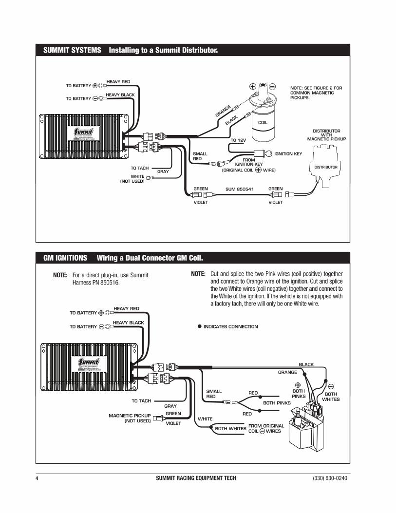
NOTE: SEE FIGURE 2 FOR COMMON MAGNETIC PICKUPS.
GRAYTO TACH
WHITE(NOT USED)
ORANGE
BLACK
SMALL RED
DISTRIBUTORWITH
MAGNETIC PICKUP
SUM 850541
COIL
SUMMIT SYSTEMS Installing to a Summit Distributor.
GM IGNITIONS Wiring a Dual Connector GM Coil.
SMALL RED
BOTH PINKS
RED
RED
ORANGE
BLACK
WHITEMAGNETIC PICKUP
(NOT USED)
GRAYTO TACH
FROM ORIGINALCOIL WIRES
NOTE: Cut and splice the two Pink wires (coil positive) together and connect to Orange wire of the ignition. Cut and splice the two White wires (coil negative) together and connect to the White of the ignition. If the vehicle is not equipped with a factory tach, there will only be one White wire.
NOTE: For a direct plug-in, use Summit Harness PN 850516.
www.summitracing.com SUMMIT RACING EQUIPMENT TECH 5
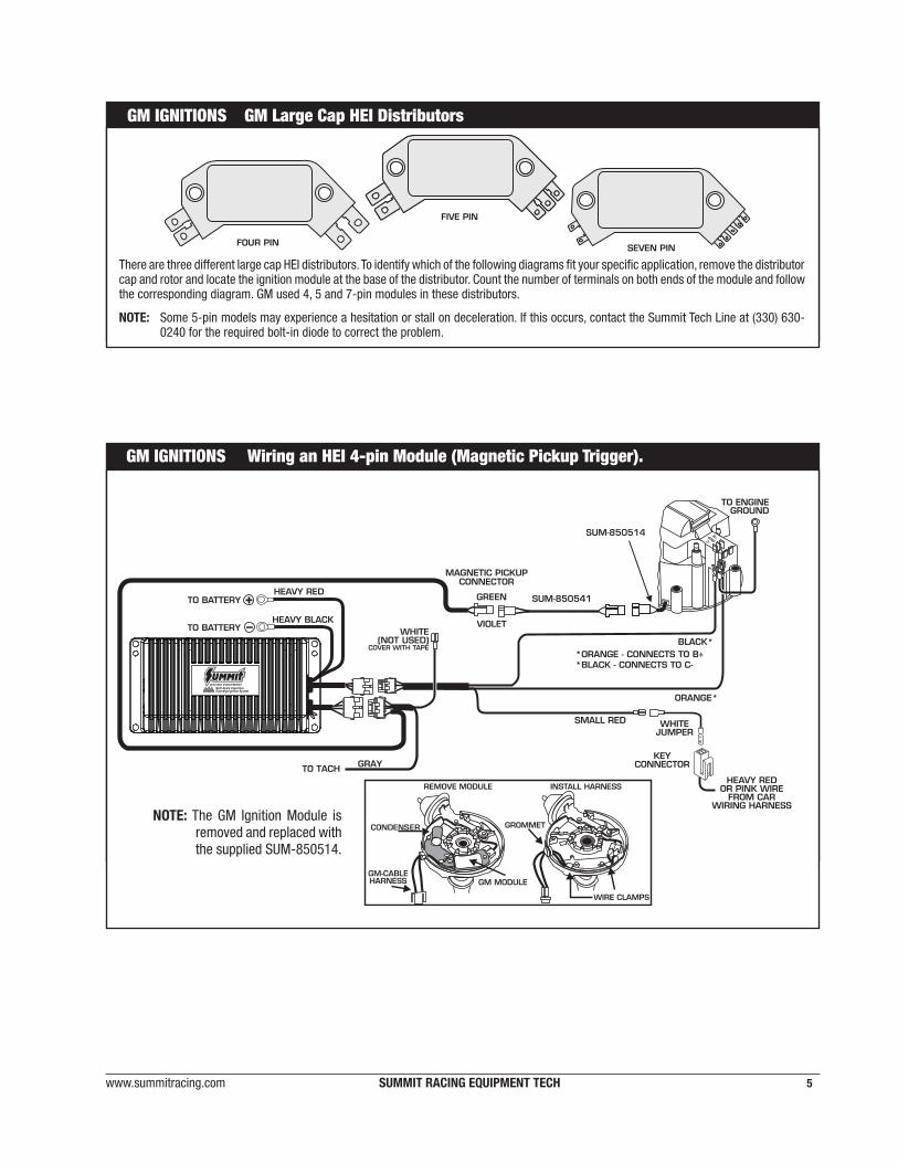
GM IGNITIONS Wiring an HEI 4-pin Module (Magnetic Pickup Trigger).
SMALL RED
SUM-850541
SUM-850514
GRAYTO TACH
NOTE: The GM Ignition Module is removed and replaced with the supplied SUM-850514.
GM IGNITIONS GM Large Cap HEI Distributors
There are three different large cap HEI distributors. To identify which of the following diagrams fit your specific application, remove the distributor cap and rotor and locate the ignition module at the base of the distributor. Count the number of terminals on both ends of the module and follow the corresponding diagram. GM used 4, 5 and 7-pin modules in these distributors.
NOTE: Some 5-pin models may experience a hesitation or stall on deceleration. If this occurs, contact the Summit Tech Line at (330) 630-0240 for the required bolt-in diode to correct the problem.
6 SUMMIT RACING EQUIPMENT TECH (330) 630-0240
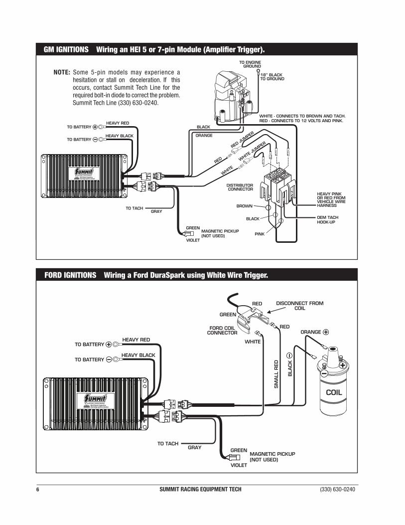
FORD IGNITIONS Wiring a Ford DuraSpark using White Wire Trigger.
COIL
SM
ALL
RED
GRAYTO TACH
MAGNETIC PICKUP(NOT USED)
GM IGNITIONS Wiring an HEI 5 or 7-pin Module (Amplifier Trigger).
GRAYTO TACH
MAGNETIC PICKUP (NOT USED)
WHITE - CONNECTS TO BROWN AND TACH.RED - CONNECTS TO 12 VOLTS AND PINK.
OEM TACHHOOK-UP
NOTE: Some 5-pin models may experience a hesitation or stall on deceleration. If this occurs, contact Summit Tech Line for the required bolt-in diode to correct the problem. Summit Tech Line (330) 630-0240.
www.summitracing.com SUMMIT RACING EQUIPMENT TECH 7
MAGNETIC PICKUPCONNECTOR
HARNESS
BLA
CK
OR
AN
GE
+
FORDDISTRIBUTOR
VIOLET ORANGE
VIOLET
BLACK(NOT USED) DISTRIBUTOR
CONNECTOR-DISCONNECT FROMORIGINAL HARNESS
GREEN
INDICATES CONNECTION
+
+ +
C+TACH
NOT USED
COIL
SM
ALL
RED
SUM-850541
GRAYTO TACH
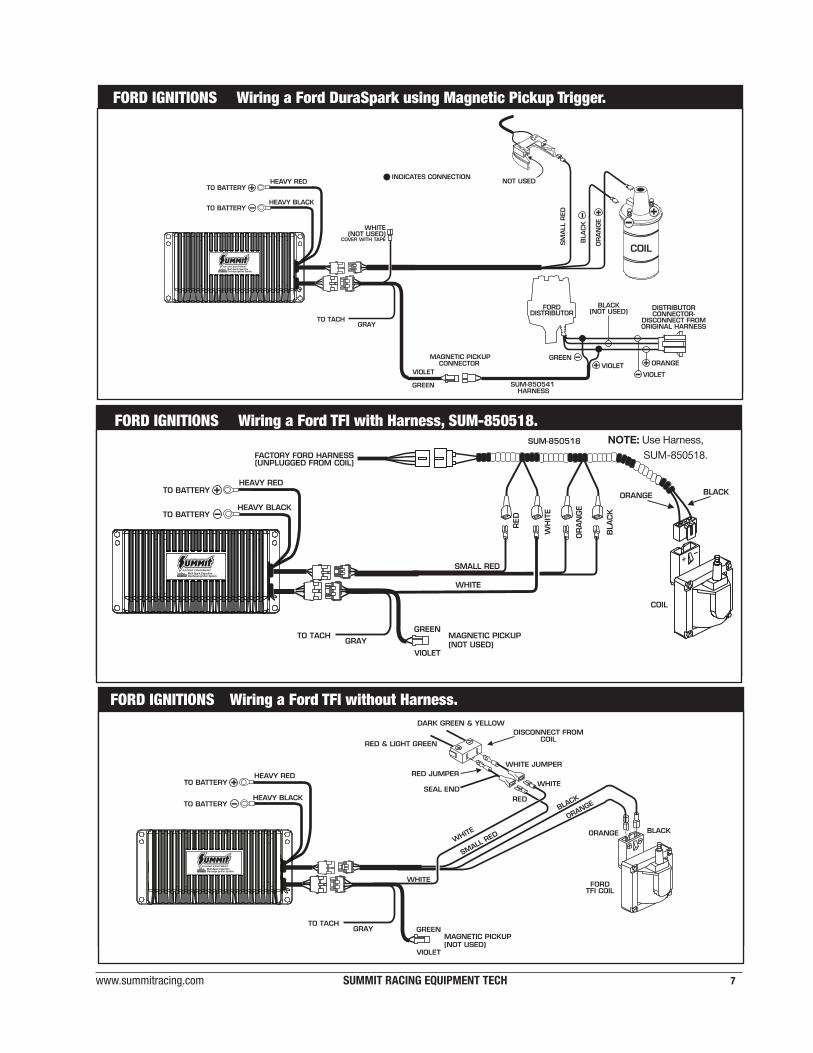
FORD IGNITIONS Wiring a Ford DuraSpark using Magnetic Pickup Trigger.
FORD IGNITIONS Wiring a Ford TFI with Harness, SUM-850518.
SMALL RED
WHITE
SUM-850518
GRAYTO TACH MAGNETIC PICKUP
(NOT USED)
FORD IGNITIONS Wiring a Ford TFI without Harness.
SMALL RED
ORANGE
WHITE
BLACK
GRAYTO TACH
MAGNETIC PICKUP(NOT USED)
WHITE
NOTE: Use Harness, SUM-850518.
8 SUMMIT RACING EQUIPMENT TECH (330) 630-0240
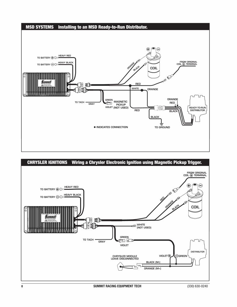
CHRYSLER IGNITIONS Wiring a Chrysler Electronic Ignition using Magnetic Pickup Trigger.
COIL
RED
ORAN
GE
BLACK
WHITE (NOT USED)
GRAYTO TACH
MSD SYSTEMS Installing to an MSD Ready-to-Run Distributor.
INDICATES CONNECTION•
ORANGE
RED
BLACK
ORANGE
BLACK
TO GROUND
READY-TO-RUNDISTRIBUTOR
RED
COILORAN
GE
BLACK
WHITE
GRAYTO TACH
RED
MAGNETIC PICKUP
(NOT USED)
www.summitracing.com SUMMIT RACING EQUIPMENT TECH 9
TROUBLESHOOTINGEvery Summit Ignition undergoes numerous quality control checks including a four hour burn-in test. If you experience a problem with your ignition, our research has shown that the majority of problems are due to improper installation or poor connections. This Troubleshooting section has several checks and tests you can perform to ensure proper installation and operation of your Summit Ignition. If you have any questions, call our Tech Line at (330) 630-0240.
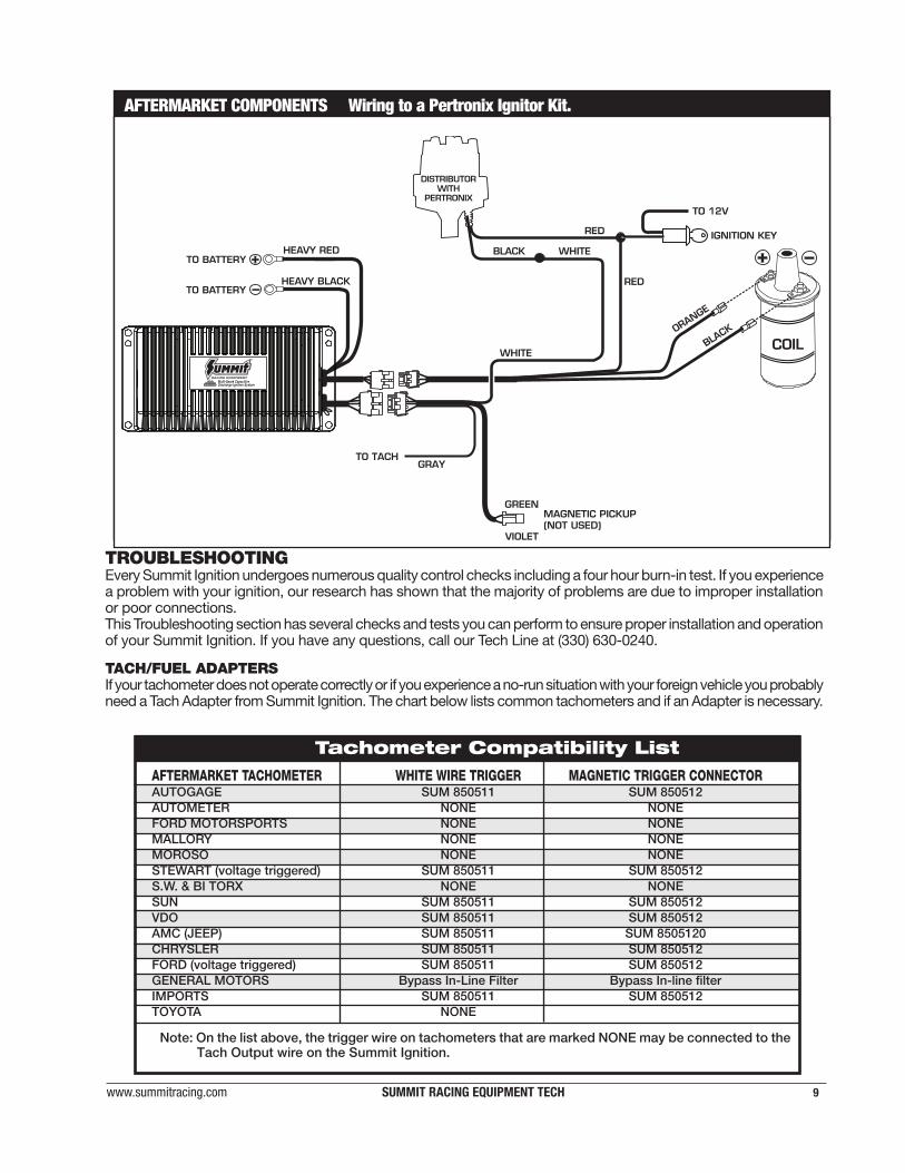
TACH/FUEL ADAPTERSIf your tachometer does not operate correctly or if you experience a no-run situation with your foreign vehicle you probably need a Tach Adapter from Summit Ignition. The chart below lists common tachometers and if an Adapter is necessary.
Tachometer Compatibility ListAFTERMARKET TACHOMETER WHITE WIRE TRIGGER MAGNETIC TRIGGER CONNECTORAUTOGAGE SUM 850511 SUM 850512AUTOMETER NONE NONEFORD MOTORSPORTS NONE NONEMALLORY NONE NONEMOROSO NONE NONESTEWART (voltage triggered) SUM 850511 SUM 850512S.W. & BI TORX NONE NONESUN SUM 850511 SUM 850512VDO SUM 850511 SUM 850512AMC (JEEP) SUM 850511 SUM 8505120CHRYSLER SUM 850511 SUM 850512FORD (voltage triggered) SUM 850511 SUM 850512GENERAL MOTORS Bypass In-Line Filter Bypass In-line filterIMPORTS SUM 850511 SUM 850512TOYOTA NONE
Note: On the list above, the trigger wire on tachometers that are marked NONE may be connected to the Tach Output wire on the Summit Ignition.
AFTERMARKET COMPONENTS Wiring to a Pertronix Ignitor Kit.
DISTRIBUTORWITH
PERTRONIX
BLACK
COIL
GRAYTO TACH
MAGNETIC PICKUP(NOT USED)
10 SUMMIT RACING EQUIPMENT TECH (330) 630-0240
ENGINE RUN-ONIf your engine continues to run even when the ignition is turned off you are experiencing engine Run-On. This usually only occurs on older vehicles with an external voltage regulator. Because this Summit Ignition receives power directly from the battery, it does not require much current to keep the unit energized. If you are experiencing Run-On, it is due to a small amount of voltage going through the charging lamp indicator and feeding the small Red wire even if the key is turned off.
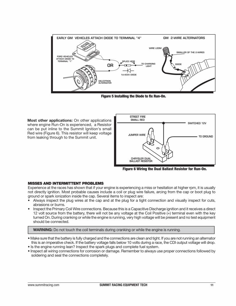
Early Ford and GM: To solve the Run-On problem, a Diode is supplied in the parts bag. By installing this Diode inline of the wire that goes to the Charging indicator, the voltage is kept from entering the Ignition. Figure 5 shows the proper installation for early Ford and GM vehicles.
Note: Diodes are used to allow voltage to flow only one way. Make sure the Diode is installed facing the proper direction (as shown in Figure 5).
Ford: Install the Diode inline to the wire going to the #1 terminal.GM: Install the Diode inline to the wire going to terminal #4. GM 1973 - 1983 with Delcotron AlternatorsGM Delcotron Alternators use an internal voltage regulator. Install the Diode inline on the smallest wire exiting the alternator (Figure 5). It is usually a Brown wire.
NO-RUN ON FOREIGN VEHICLESSome foreign vehicles with fuel injection systems may require a Summit Tach/Fuel Injection Adapter to run with the Summit Ignition. This is because many of these systems use the same trigger source to operate the Ignition, the tachometer and the fuel injection. This results in a voltage signal that is too low to accurately trigger the fuel injection. To fix this, a Summit Tach Adapter, SUM-850511, will remedy the problem on the majority of vehicles. If the SUM 850511 does not fix the problem, the SUM-850512 will be required.
Note: Toyotas and Ford Probes will require an Adapter.
INOPERATIVE TACHOMETERSIf your tachometer fails to operate with the Summit Ignition installed, you may need a Tach Adapter. Before getting an adapter, try connecting your tachometer trigger wire to the Gray Wire. This output produces a 12 volt, square wave (see page 1). If the tach still does not operate, you will need a Tach Adapter. There are two Tach Adapters:
SUM-850512: If you are using the Magnetic Pickup connector (Green and Violet wires) to trigger the CDI, you will need the SUM-850512.
SUM-850511: If your tachometer was triggered from the coil negative terminal (voltage trigger) and you are using the White wire to trigger the CDI you will need the SUM-850511.
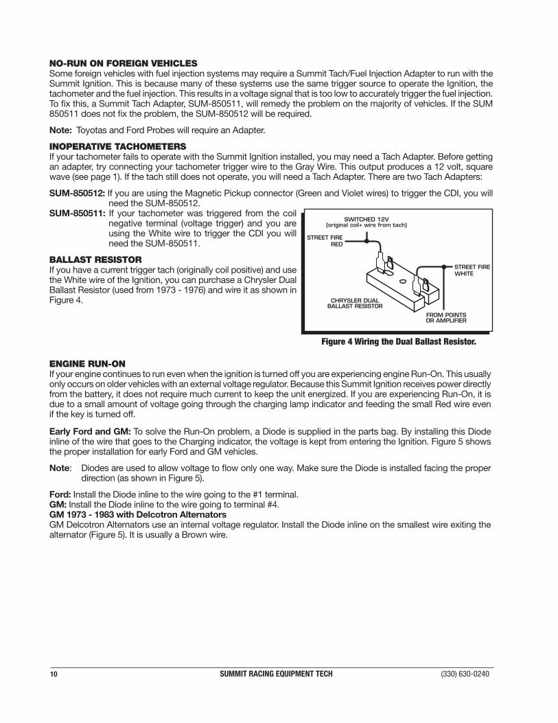
BALLAST RESISTORIf you have a current trigger tach (originally coil positive) and use the White wire of the Ignition, you can purchase a Chrysler Dual Ballast Resistor (used from 1973 - 1976) and wire it as shown in Figure 4.
FROM POINTSOR AMPLIFIER
STREET FIREWHITE
STREET FIRERED
SWITCHED 12V(original coil+ wire from tach)
CHRYSLER DUALBALLAST RESISTOR
Figure 4 Wiring the Dual Ballast Resistor.
www.summitracing.com SUMMIT RACING EQUIPMENT TECH 11
1A-400V DIODE
TO CHARGINGLIGHT
SPLICE HERE
OR
DELCOTRONALTERNATOR
FORD VEHICLESATTACH DIODE TO
TERMINAL "1"
EARLY GM VEHICLES ATTACH DIODE TO TERMINAL "4"
12
34 SMALLER OF THE 2-WIRES
DIODE
WIRE LOOM
GM 2-WIRE ALTERNATORS
Figure 5 Installing the Diode to fix Run-On.
Most other applications: On other applications where engine Run-On is experienced, a Resistor can be put inline to the Summit Ignition's small Red wire (Figure 6). This resistor will keep voltage from leaking through to the Summit unit.
STREET FIRE
Figure 6 Wiring the Dual Ballast Resistor for Run-On.
MISSES AND INTERMITTENT PROBLEMSExperience at the races has shown that if your engine is experiencing a miss or hesitation at higher rpm, it is usually not directly ignition. Most probable causes include a coil or plug wire failure, arcing from the cap or boot plug to ground or spark ionization inside the cap. Several items to inspect are:• Always inspect the plug wires at the cap and at the plug for a tight connection and visually inspect for cuts,
abrasions or burns.• Inspect the Primary Coil Wire connections. Because this is a Capacitive Discharge ignition and it receives a direct
12 volt source from the battery, there will not be any voltage at the Coil Positive (+) terminal even with the key turned On. During cranking or while the engine is running, very high voltage will be present and no test equipment should be connected.
WARNING: Do not touch the coil terminals during cranking or while the engine is running.
• Make sure that the battery is fully charged and the connections are clean and tight. If you are not running an alternator this is an imperative check. If the battery voltage falls below 10 volts during a race, the CDI output voltage will drop.
• Is the engine running lean? Inspect the spark plugs and complete fuel system.• Inspect all wiring connections for corrosion or damage. Remember to always use proper connections followed by
soldering and seal the connections completely.
12 SUMMIT RACING EQUIPMENT TECH (330) 630-0240
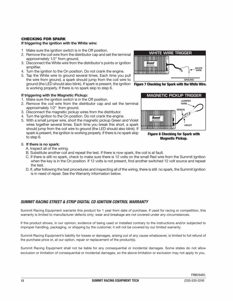
CHECKING FOR SPARKIf triggering the ignition with the White wire:
1 Make sure the ignition switch is in the Off position.2. Remove the coil wire from the distributor cap and set the terminal
approximately 1/2" from ground. 3. Disconnect the White wire from the distributor's points or ignition
amplifier. 4. Turn the ignition to the On position. Do not crank the engine.5. Tap the White wire to ground several times. Each time you pull
the wire from ground, a spark should jump from the coil wire to ground (the LED should also blink). If spark is present, the ignition is working properly. If there is no spark skip to step 6.
If triggering with the Magnetic Pickup:1. Make sure the ignition switch is in the Off position.2. Remove the coil wire from the distributor cap and set the terminal
approximately 1/2" from ground. 3. Disconnect the magnetic pickup wires from the distributor. 4. Turn the ignition to the On position. Do not crank the engine.5. With a small jumper wire, short the magnetic pickup Green and Violet
wires together several times. Each time you break this short, a spark should jump from the coil wire to ground (the LED should also blink). If spark is present, the ignition is working properly. If there is no spark skip to step 6.
6. If there is no spark:A. Inspect all of the wiring. B. Substitute another coil and repeat the test. If there is now spark, the coil is at fault.C. If there is still no spark, check to make sure there is 12 volts on the small Red wire from the Summit Ignition
when the key is in the On position. If 12 volts is not present, find another switched 12 volt source and repeat the test.
D. If, after following the test procedures and inspecting all of the wiring, there is still no spark, the Summit Ignition is in need of repair. See the Warranty information below.
Figure 7 Checking for Spark with the White Wire.
WHITE WIRE TRIGGER
VIOLET
GREEN
JUMPERWIRE
MAGNETIC PICKUP TRIGGER
Figure 8 Checking for Spark with Magnetic Pickup.
SUMMIT RACING STREET & STRIP DIGITAL CD IGNITION CONTROL WARRANTY
Summit Racing Equipment warrants this product for 1 year from date of purchase. If used for racing or competition, this warranty is limited to manufacturer defects only; wear and breakage are not covered under any circumstances.
If the product shows, in our opinion, evidence of being used or installed contrary to the instructions and/or subjected to improper handling, packaging, or shipping by the customer, it will not be covered by our limited warranty.
Summit Racing Equipment’s liability for losses or damages, arising out of any cause whatsoever, is limited to full refund of the purchase price or, at our option, repair or replacement of the product(s).
Summit Racing Equipment shall not be liable for any consequential or incidental damages. Some states do not allow exclusion or limitation of consequential or incidental damages, so the above limitation or exclusion may not apply to you.
FRM29485.