Embed Size (px)
DESCRIPTION
Sun Enterprise 6x00, 5x00, 4x00,and 3x00 Systems DynamicReconfiguration User’s Guide
Citation preview
Sun Enterprise 6x00, 5x00, 4x00,and 3x00 Systems DynamicReconfiguration User’s Guide
901 San Antonio RoadPalo Alto, , CA 94303-4900
USA 650 960-1300 Fax 650 969-9131
Part No: 806-0280-10Revision A, May 1999
Copyright 1999 Sun Microsystems, Inc. 901 San Antonio Road, Palo Alto, California 94303-4900 U.S.A. All rights reserved.This product or document is protected by copyright and distributed under licenses restricting its use, copying, distribution, anddecompilation. No part of this product or document may be reproduced in any form by any means without prior written authorization ofSun and its licensors, if any.Portions of this product may be derived from the UNIX® system, licensed from Novell, Inc., and from the Berkeley 4.3 BSD system,licensed from the University of California. UNIX is a registered trademark in the United States and in other countries and is exclusivelylicensed by X/Open Company Ltd. Third-party software, including font technology in this product, is protected by copyright and licensedfrom Sun’s suppliers. RESTRICTED RIGHTS: Use, duplication, or disclosure by the U.S. Government is subject to restrictions of FAR52.227-14(g)(2)(6/87) and FAR 52.227-19(6/87), or DFAR 252.227-7015(b)(6/95) and DFAR 227.7202-3(a).Sun, Sun Microsystems, the Sun logo, Solstice DiskSuite, Sun Enterprise Volume Manager, Sun RSM Array, Sun Enterprise SyMON, andSolaris are trademarks or registered trademarks of Sun Microsystems, Inc. in the United States and in other countries. All SPARCtrademarks are used under license and are trademarks or registered trademarks of SPARC International, Inc. in the United States and inother countries. Products bearing SPARC trademarks are based upon an architecture developed by Sun Microsystems, Inc.The OPEN LOOK® and Sun
TM
Graphical User Interfaces were developed by Sun Microsystems, Inc. for its users and licensees. Sunacknowledges the pioneering efforts of Xerox Corporation in researching and developing the concept of visual or graphical user interfacesfor the computer industry. Sun holds a nonexclusive license from Xerox to the Xerox Graphical User Interface, which license also coversSun’s licensees who implement OPEN LOOK GUIs and otherwise comply with Sun’s written license agreements.THIS PUBLICATION IS PROVIDED“AS IS” WITHOUT WARRANTY OF ANY KIND, EITHER EXPRESS OR IMPLIED, INCLUDING,BUT NOT LIMITED TO, THE IMPLIED WARRANTIES OF MERCHANTABILITY, FITNESS FOR A PARTICULAR PURPOSE, ORNON-INFRINGEMENT.Copyright 1999 Sun Microsystems, Inc., 901 San Antonio Road, Palo Alto, Californie 94303-4900 U.S.A. Tous droits réservés.Ce produit ou document est protégé par un copyright et distribué avec des licences qui en restreignent l’utilisation, la copie et ladécompilation. Aucune partie de ce produit ou de sa documentation associée ne peut être reproduite sous aucune forme, par quelquemoyen que ce soit, sans l’autorisation préalable et écrite de Sun et de ses bailleurs de licence, s’il y en a.Des parties de ce produit pourront être derivées du système UNIX® licencié par Novell, Inc. et du système Berkeley 4.3 BSD licencié parl’Université de Californie. UNIX est une marque enregistrée aux Etats-Unis et dans d’autres pays, et licenciée exclusivement par X/OpenCompany Ltd. Le logiciel détenu par des tiers, et qui comprend la technologie relative aux polices de caractères, est protégé par uncopyright et licencié par des fournisseurs de Sun.Sun, Sun Microsystems, le logo Sun, Solstice DiskSuite, Sun Enterprise Volume Manager, Sun RSM Array, Sun Enterprise SyMON, etSolaris sont des marques déposées ou enregistrées de Sun Microsystems, Inc. aux Etats-Unis et dans d’autres pays. Toutes les marquesSPARC, utilisées sous licence, sont des marques déposées ou enregistrées de SPARC International, Inc. aux Etats-Unis et dans d’autrespays. Les produits portant les marques SPARC sont basés sur une architecture développée par Sun Microsystems, Inc.Les utilisateurs d’interfaces graphiques OPEN LOOK® et Sun
TM
ont été développés de Sun Microsystems, Inc. pour ses utilisateurs etlicenciés. Sun reconnaît les efforts de pionniers de Xerox Corporation pour la recherche et le développement du concept des interfacesd’utilisation visuelle ou graphique pour l’industrie de l’informatique. Sun détient une licence non exclusive de Xerox sur l’interfaced’utilisation graphique, cette licence couvrant aussi les licenciés de Sun qui mettent en place les utilisateurs d’interfaces graphiques OPENLOOK et qui en outre se conforment aux licences écrites de Sun.CETTE PUBLICATION EST FOURNIE "EN L’ETAT" SANS GARANTIE D’AUCUNE SORTE, NI EXPRESSE NI IMPLICITE, Y COMPRIS,ET SANS QUE CETTE LISTE NE SOIT LIMITATIVE, DES GARANTIES CONCERNANT LA VALEUR MARCHANDE, L’APTITUDE DESPRODUITS A REPONDRE A UNE UTILISATION PARTICULIERE OU LE FAIT QU’ILS NE SOIENT PAS CONTREFAISANTS DEPRODUITS DE TIERS.
PleaseRecycle
Contents
Preface vii
1. Overview 1
How to Locate Service Procedures and Related Information 1
Sun Enterprise DR Web Site 2
Software Patches 2
Limitations 3
Hardware 3
Firmware 4
Displaying Board Status 5
Basic Status Display 5
Detailed Status Display 6
Terminology 8
The cfgadm Command 8
cfgadm Conditions 9
Naming Conventions for Memory Banks and CPU Numbers 12
Attachment Point 13
Conditions and States 14
Connection and Configuration 15
Hot-Plug Hardware 15
Contents iii
Quiescence 16
Discussion of Board or Device Installation 17
Connecting a Board 17
Configuring a Board 18
Using a Board as a Spare 19
Enabling an Unconfigured Board 19
Addition of Storage Devices 19
Discussion of Board Removal 19
Memory Device Preparation 20
I/O and Network Device Preparation 20
I/O Board Unconfiguration 20
Discussion of Board and Device Replacement or Modification 21
Replacement Sequence 21
Discussion of System Reconfiguration 22
When to Reconfigure 22
I/O Device Reconfiguration 22
Disk Controller Renumbering During a Reconfiguration 23
2. Procedures 25
SPARC: Displaying PROM Versions 25
Testing for Suspend-Safe Drivers 26
Enabling Dynamic Reconfiguration 27
Removing a Board 27
Removing a CPU/Memory Board 27
Removing an I/O Board 30
Removing Boards That Use Detach-Unsafe Drivers 34
Temporarily Unconfiguring a Board 35
Installing a Board 36
Installing or Replacing a CPU/Memory Board 37
iv Sun Enterprise 6x00, 5x00, 4x00, and 3x00 Systems Dynamic Reconfiguration User’s Guide ♦ Revision A, May1999
Installing a New I/O Board 39
Installing a Replacement I/O Board 41
Adding Storage Devices 42
Preparing a Spare Board 43
Disabling a Board 43
Enabling Spare Boards 44
3. Troubleshooting 45
Troubleshooting Specific Failures 45
Diagnostic Messages 45
Driver Does Not Support Dynamic Reconfiguration 46
Unconfigure Operation Fails 46
CPU/Memory Board Unconfiguration Failure 46
I/O Board Unconfiguration Failure 48
Configure Operation Fails 50
CPU/Memory Board Configuration Failure 50
I/O Board Configuration Failure 50
Disabled Board List 51
Glossary 53
Contents v

vi Sun Enterprise 6x00, 5x00, 4x00, and 3x00 Systems Dynamic Reconfiguration User’s Guide ♦ Revision A, May1999
Preface
The information in this book is intended for the system administrator and serviceprovider.
This user’s guide describes the Dynamic Reconfiguration (DR) feature, which enablesyou to attach and detach system boards from a running system. The information inthis user guide applies to these Sun EnterpriseTM systems:
� Sun Enterprise 6500 system
� Sun Enterprise 6000 system
� Sun Enterprise 5500 system
� Sun Enterprise 5000 system
� Sun Enterprise 4500 system
� Sun Enterprise 4000 system
� Sun Enterprise 3500 system
� Sun Enterprise 3000 system
How This Book Is OrganizedChapter 1 gives a general description of Dynamic Reconfiguration (DR).
Chapter 2 provides step-by-step DR procedures.
Chapter 3 has information for troubleshooting DR problems.
Glossary defines the technical terms used in this book.
Preface vii
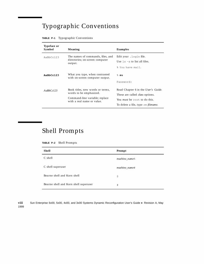
Typographic Conventions
TABLE P–1 Typographic Conventions
Typeface orSymbol Meaning Examples
AaBbCc123 The names of commands, files, anddirectories; on-screen computeroutput.
Edit your .login file.
Use ls -a to list all files.
% You have mail .
AaBbCc123 What you type, when contrastedwith on-screen computer output.
%su
Password:
AaBbCc123 Book titles, new words or terms,words to be emphasized.
Command-line variable; replacewith a real name or value.
Read Chapter 6 in the User’s Guide.
These are called class options.
You must be root to do this.
To delete a file, type rm filename.
Shell Prompts
TABLE P–2 Shell Prompts
Shell Prompt
C shell machine_name%
C shell superuser machine_name#
Bourne shell and Korn shell $
Bourne shell and Korn shell superuser #
viii Sun Enterprise 6x00, 5x00, 4x00, and 3x00 Systems Dynamic Reconfiguration User’s Guide ♦ Revision A, May1999
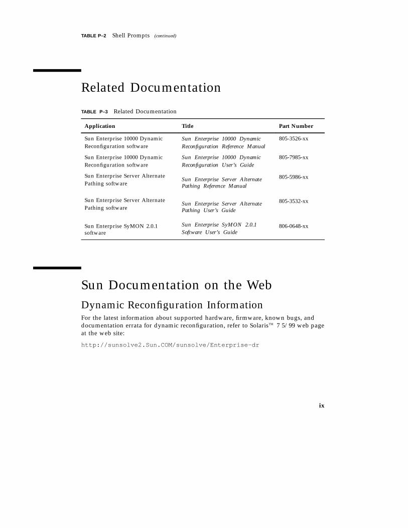
TABLE P–2 Shell Prompts (continued)
Related Documentation
TABLE P–3 Related Documentation
Application Title Part Number
Sun Enterprise 10000 DynamicReconfiguration software
Sun Enterprise 10000 DynamicReconfiguration Reference Manual
805-3526-xx
Sun Enterprise 10000 DynamicReconfiguration software
Sun Enterprise 10000 DynamicReconfiguration User’s Guide
805-7985-xx
Sun Enterprise Server AlternatePathing software
Sun Enterprise Server AlternatePathing Reference Manual
805-5986-xx
Sun Enterprise Server AlternatePathing software
Sun Enterprise Server AlternatePathing User’s Guide
805-3532-xx
Sun Enterprise SyMON 2.0.1software
Sun Enterprise SyMON 2.0.1Software User’s Guide
806-0648-xx
Sun Documentation on the WebDynamic Reconfiguration InformationFor the latest information about supported hardware, firmware, known bugs, anddocumentation errata for dynamic reconfiguration, refer to SolarisTM 7 5/99 web pageat the web site:
http://sunsolve2.Sun.COM/sunsolve/Enterprise-dr
ix
Obtaining Sun DocumentsThe docs.sun.com web site enables you to access Sun technical documentation onthe Web. You can browse the docs.sun.com archive or search for a specific booktitle or subject at:
http://docs.sun.com
Sun Welcomes Your CommentsWe are interested in improving our documentation and welcome your comments andsuggestions. You can email your comments to us at:
Please include the part number of your document in the subject line of your email.
x Sun Enterprise 6x00, 5x00, 4x00, and 3x00 Systems Dynamic Reconfiguration User’s Guide ♦ Revision A, May1999
CHAPTER 1
Overview
Dynamic reconfiguration (DR) is an operating environment feature that provides theability to reconfigure system hardware while the system is running. This feature isoptional and can be implemented at the discretion of the system administrator. Themain benefit of DR is that a service provider can add or replace hardware resources(such as CPUs, memory, and I/O interfaces) with little interruption of normal systemoperations.
DR is available for SunTM system architectures that contain multiple system boardsand use board sockets that support hot-plugging. The DR features described in thisuser’s guide are specific to Sun Enterprise
TM
6500, 6000, 5500, 5000, 4500, 4000, 3500,and 3000 systems using the 5/99 release of the SolarisTM 7 operating environment.These features may not apply to other types of server systems.
For information about DR for Sun Enterprise 10000 systems, refer to the SunEnterprise 10000 Dynamic Reconfiguration User’s Guide.
The Sun Enterprise SyMONTM system monitoring and management software supportsdynamic reconfiguration, including features described in this user guide. For moreinformation, refer to the Sun Enterprise SyMON 2.0.1 Software User’s Guide.
Note - For the sake of brevity, the rest of this document refers to an individualsystem as a “Sun Enterprise xx00 system”, or simply as “the system”.
How to Locate Service Procedures andRelated Information� To determine what types of boards are supported, see “Limitations ” on page 3
1
� To find the system name of a board or device and check its status, see“Displaying Board Status” on page 5
� To install a board, see “Installing a Board” on page 36
� To remove or replace a board, see “Removing a Board” on page 27
� To remove a device driver that does not support Dynamic Reconfiguration, see“Removing Boards That Use Detach-Unsafe Drivers” on page 34
� To connect storage devices to an I/O board, see “Adding Storage Devices” onpage 42
Sun Enterprise DR Web SiteFor late-breaking news and patch information, visit the Solaris 7 5/99 web page at:
http://sunsolve2.Sun.COM/sunsolve/Enterprise-dr
The web site is updated periodically.
If you do not have access to this web site, ask your Sun service provider forassistance in obtaining the latest information.
Software PatchesFor software patch requirements, visit the Solaris 7 5/99 web page at the DR website noted in the previous section.
Note - SAP R/3 software requires patches to support dynamic reconfiguration. SAPR/3 versions 3.1I and 4.0B currently require the patches dw1_310.CAR ,dw2_310.CAR , and sapstart , dated February 1999, but this list is subject to changeat any time. Refer to the web page above for any new information about thesepatches.
2 Sun Enterprise 6x00, 5x00, 4x00, and 3x00 Systems Dynamic Reconfiguration User’s Guide ♦ Revision A, May1999
LimitationsHardware
Hot Plug SupportIf you see the following message on your console or in your console logs, thehardware cannot be removed while the system is powered up and does not supportDR.
Hot Plug not supported in this system
Board SupportDR may not be fully supported on all board types at this time, although additionalsupport is being developed. For late-breaking news, refer to the Solaris 7 5/99section at the DR web site. See “Sun Enterprise DR Web Site” on page 2.
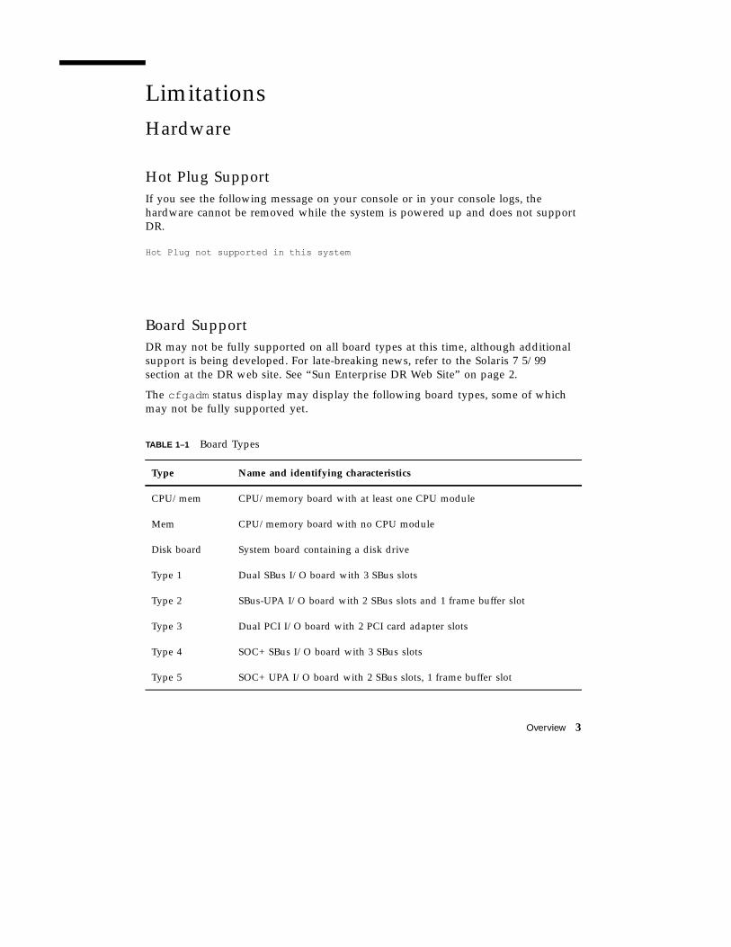
The cfgadm status display may display the following board types, some of whichmay not be fully supported yet.
TABLE 1–1 Board Types
Type Name and identifying characteristics
CPU/mem CPU/memory board with at least one CPU module
Mem CPU/memory board with no CPU module
Disk board System board containing a disk drive
Type 1 Dual SBus I/O board with 3 SBus slots
Type 2 SBus-UPA I/O board with 2 SBus slots and 1 frame buffer slot
Type 3 Dual PCI I/O board with 2 PCI card adapter slots
Type 4 SOC+ SBus I/O board with 3 SBus slots
Type 5 SOC+ UPA I/O board with 2 SBus slots, 1 frame buffer slot
Overview 3
TABLE 1–1 Board Types (continued)
Broken Boards
Caution - Inserting a broken (malfunctioning) board may cause a system crash. Useonly boards that are known to be functional.
Non-Detachable BoardsIf the cfgadm -v status display identifies a board as “non-detachable”, the boardcannot be dynamically reconfigured. The lowest-numbered CPU/memory board iscurrently in this category and cannot be removed while the system is running.Support is being developed for these board locations.
Memory InterleavingMemory boards or CPU/memory boards that contain interleaved memory currentlycannot be dynamically reconfigured. To list boards with interleaved memory, use theprtdiag or cfgadm commands.
Permanent MemoryA CPU/memory board containing non-relocatable memory cannot be dynamicallyreconfigured. Typically, this condition applies to one CPU/memory board in thesystem. The board is identified as “PERMANENT” in the status display produced bythe cfgadm -v command.
Firmware
General Support for Dynamic ReconfigurationYour machine may require firmware updates to dynamically reconfigure. Look forsystem messages when the system boots.
Older versions of the CPU PROM may display the following message:
Firmware does not support Dynamic Reconfiguration
4 Sun Enterprise 6x00, 5x00, 4x00, and 3x00 Systems Dynamic Reconfiguration User’s Guide ♦ Revision A, May1999
More recent versions of the CPU PROM may display variations of this message.
CPU/Memory Board FirmwareTo support DR in the Solaris 7 5/99 operating environment, CPU/memory boardsmay require a PROM upgrade. Instructions for obtaining the CPU upgrade firmwareare available at the Solaris 7 5/99 section at the DR web site. See “Sun Enterprise DRWeb Site” on page 2.
To list board PROM versions, see “SPARC: Displaying PROM Versions” on page 25.
Firmware for FC-AL Disk Arrays or Internal DrivesFor Sun StorEdgeTM A5000 disk arrays, or for internal FC-AL disks in the SunEnterprise 3500 system, the firmware version must be ST19171FC 0413 or later. Formore information, refer to the Solaris 7 5/99 section at the DR web site. See “SunEnterprise DR Web Site” on page 2.
Displaying Board StatusThe cfgadm program displays information about boards and slots. Refer to thecfgadm(1) man page for options to this command.
Basic Status DisplayMany operations require that you specify the system board names. To obtain thesesystem names, type:
# cfgadm
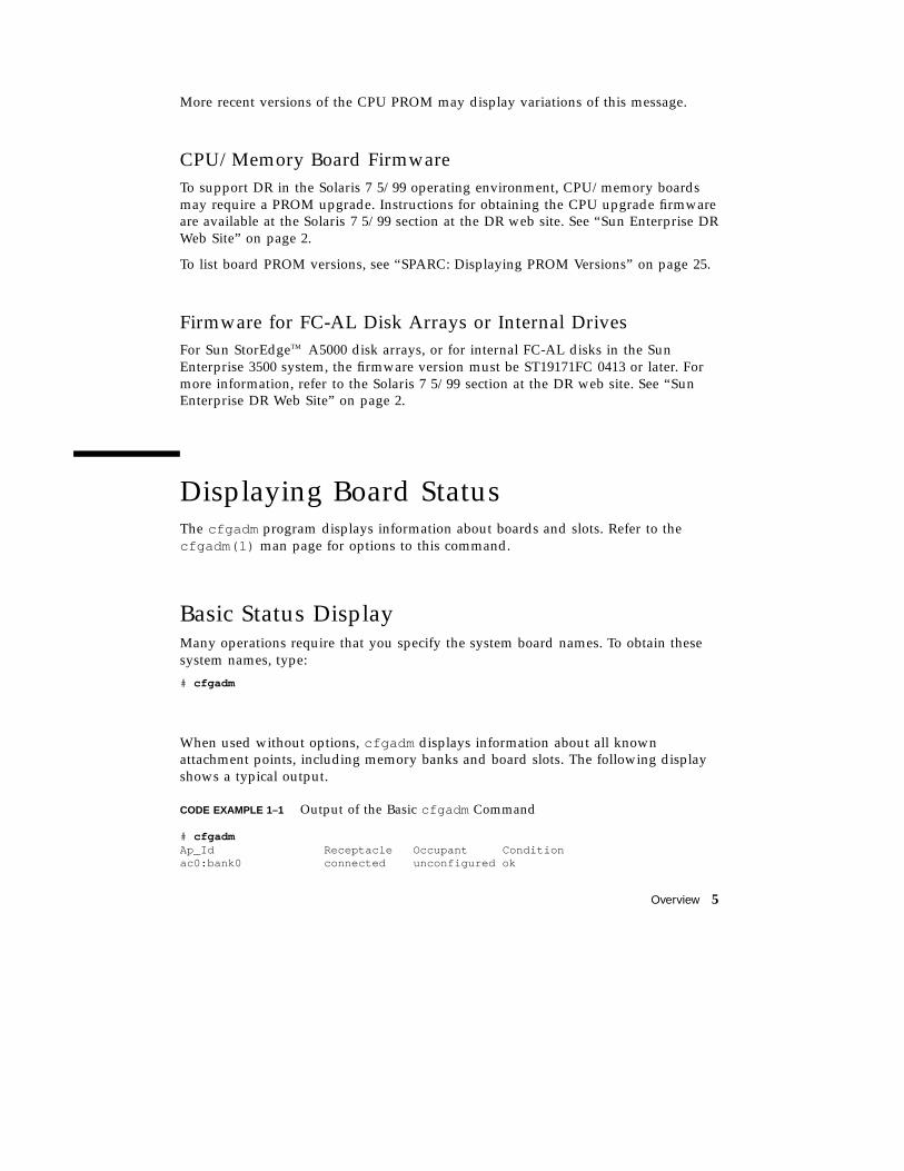
When used without options, cfgadm displays information about all knownattachment points, including memory banks and board slots. The following displayshows a typical output.
CODE EXAMPLE 1–1 Output of the Basic cfgadm Command
# cfgadmAp_Id Receptacle Occupant Conditionac0:bank0 connected unconfigured ok
Overview 5
ac0:bank1 empty unconfigured unknownac1:bank0 connected unconfigured okac1:bank1 empty unconfigured unknownac2:bank0 connected configured okac2:bank1 empty unconfigured unknownac3:bank0 empty unconfigured unknownac3:bank1 empty unconfigured unknownac4:bank0 empty unconfigured unknownac4:bank1 connected unconfigured okac8:bank0 empty unconfigured unknownac8:bank1 empty unconfigured unknownsysctrl0:slot0 connected configured oksysctrl0:slot1 connected configured oksysctrl0:slot2 connected configured oksysctrl0:slot3 empty unconfigured unknownsysctrl0:slot4 empty unconfigured unusablesysctrl0:slot5 connected configured oksysctrl0:slot6 empty unconfigured unusablesysctrl0:slot7 empty unconfigured unknownsysctrl0:slot8 connected configured oksysctrl0:slot9 connected configured oksysctrl0:slot10 connected configured oksysctrl0:slot11 connected configured oksysctrl0:slot12 empty unconfigured unusablesysctrl0:slot13 disconnected unconfigured unknownsysctrl0:slot14 empty unconfigured unusablesysctrl0:slot15 disconnected unconfigured unknown
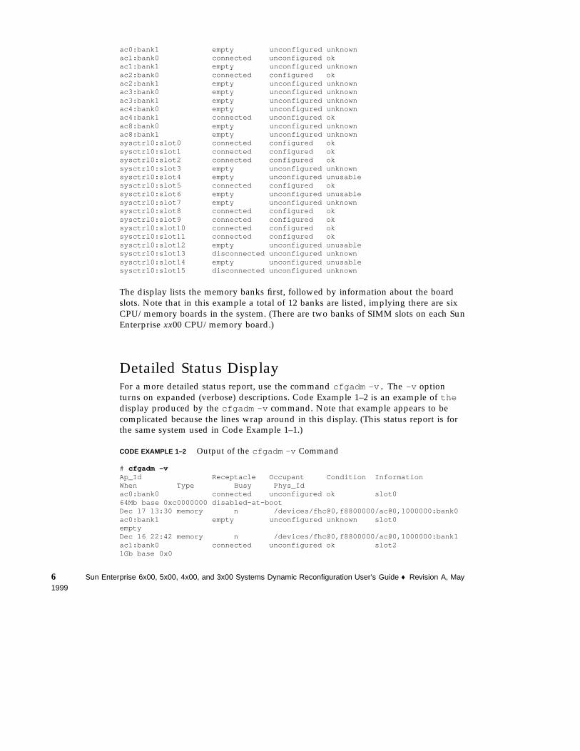
The display lists the memory banks first, followed by information about the boardslots. Note that in this example a total of 12 banks are listed, implying there are sixCPU/memory boards in the system. (There are two banks of SIMM slots on each SunEnterprise xx00 CPU/memory board.)
Detailed Status DisplayFor a more detailed status report, use the command cfgadm -v. The -v optionturns on expanded (verbose) descriptions. Code Example 1–2 is an example of thedisplay produced by the cfgadm -v command. Note that example appears to becomplicated because the lines wrap around in this display. (This status report is forthe same system used in Code Example 1–1.)
CODE EXAMPLE 1–2 Output of the cfgadm -v Command
# cfgadm -vAp_Id Receptacle Occupant Condition InformationWhen Type Busy Phys_Idac0:bank0 connected unconfigured ok slot064Mb base 0xc0000000 disabled-at-bootDec 17 13:30 memory n /devices/fhc@0,f8800000/ac@0,1000000:bank0ac0:bank1 empty unconfigured unknown slot0emptyDec 16 22:42 memory n /devices/fhc@0,f8800000/ac@0,1000000:bank1ac1:bank0 connected unconfigured ok slot21Gb base 0x0
6 Sun Enterprise 6x00, 5x00, 4x00, and 3x00 Systems Dynamic Reconfiguration User’s Guide ♦ Revision A, May1999
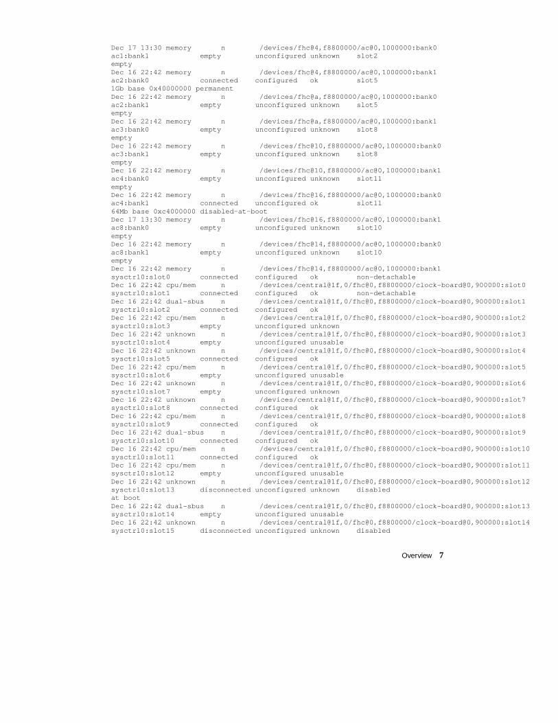
Dec 17 13:30 memory n /devices/fhc@4,f8800000/ac@0,1000000:bank0ac1:bank1 empty unconfigured unknown slot2emptyDec 16 22:42 memory n /devices/fhc@4,f8800000/ac@0,1000000:bank1ac2:bank0 connected configured ok slot51Gb base 0x40000000 permanentDec 16 22:42 memory n /devices/fhc@a,f8800000/ac@0,1000000:bank0ac2:bank1 empty unconfigured unknown slot5emptyDec 16 22:42 memory n /devices/fhc@a,f8800000/ac@0,1000000:bank1ac3:bank0 empty unconfigured unknown slot8emptyDec 16 22:42 memory n /devices/fhc@10,f8800000/ac@0,1000000:bank0ac3:bank1 empty unconfigured unknown slot8emptyDec 16 22:42 memory n /devices/fhc@10,f8800000/ac@0,1000000:bank1ac4:bank0 empty unconfigured unknown slot11emptyDec 16 22:42 memory n /devices/fhc@16,f8800000/ac@0,1000000:bank0ac4:bank1 connected unconfigured ok slot1164Mb base 0xc4000000 disabled-at-bootDec 17 13:30 memory n /devices/fhc@16,f8800000/ac@0,1000000:bank1ac8:bank0 empty unconfigured unknown slot10emptyDec 16 22:42 memory n /devices/fhc@14,f8800000/ac@0,1000000:bank0ac8:bank1 empty unconfigured unknown slot10emptyDec 16 22:42 memory n /devices/fhc@14,f8800000/ac@0,1000000:bank1sysctrl0:slot0 connected configured ok non-detachableDec 16 22:42 cpu/mem n /devices/central@1f,0/fhc@0,f8800000/clock-board@0,900000:slot0sysctrl0:slot1 connected configured ok non-detachableDec 16 22:42 dual-sbus n /devices/central@1f,0/fhc@0,f8800000/clock-board@0,900000:slot1sysctrl0:slot2 connected configured okDec 16 22:42 cpu/mem n /devices/central@1f,0/fhc@0,f8800000/clock-board@0,900000:slot2sysctrl0:slot3 empty unconfigured unknownDec 16 22:42 unknown n /devices/central@1f,0/fhc@0,f8800000/clock-board@0,900000:slot3sysctrl0:slot4 empty unconfigured unusableDec 16 22:42 unknown n /devices/central@1f,0/fhc@0,f8800000/clock-board@0,900000:slot4sysctrl0:slot5 connected configured okDec 16 22:42 cpu/mem n /devices/central@1f,0/fhc@0,f8800000/clock-board@0,900000:slot5sysctrl0:slot6 empty unconfigured unusableDec 16 22:42 unknown n /devices/central@1f,0/fhc@0,f8800000/clock-board@0,900000:slot6sysctrl0:slot7 empty unconfigured unknownDec 16 22:42 unknown n /devices/central@1f,0/fhc@0,f8800000/clock-board@0,900000:slot7sysctrl0:slot8 connected configured okDec 16 22:42 cpu/mem n /devices/central@1f,0/fhc@0,f8800000/clock-board@0,900000:slot8sysctrl0:slot9 connected configured okDec 16 22:42 dual-sbus n /devices/central@1f,0/fhc@0,f8800000/clock-board@0,900000:slot9sysctrl0:slot10 connected configured okDec 16 22:42 cpu/mem n /devices/central@1f,0/fhc@0,f8800000/clock-board@0,900000:slot10sysctrl0:slot11 connected configured okDec 16 22:42 cpu/mem n /devices/central@1f,0/fhc@0,f8800000/clock-board@0,900000:slot11sysctrl0:slot12 empty unconfigured unusableDec 16 22:42 unknown n /devices/central@1f,0/fhc@0,f8800000/clock-board@0,900000:slot12sysctrl0:slot13 disconnected unconfigured unknown disabledat bootDec 16 22:42 dual-sbus n /devices/central@1f,0/fhc@0,f8800000/clock-board@0,900000:slot13sysctrl0:slot14 empty unconfigured unusableDec 16 22:42 unknown n /devices/central@1f,0/fhc@0,f8800000/clock-board@0,900000:slot14sysctrl0:slot15 disconnected unconfigured unknown disabled
Overview 7
at bootDec 16 22:42 dual-sbus n /devices/central@1f,0/fhc@0,f8800000/clock-board@0,900000:slot15
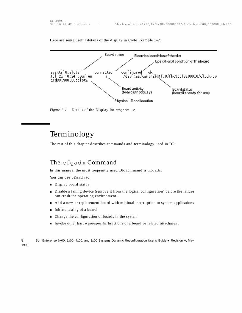
Here are some useful details of the display in Code Example 1–2:
Figure 1–1 Details of the Display for cfgadm -v
TerminologyThe rest of this chapter describes commands and terminology used in DR.
The cfgadm CommandIn this manual the most frequently used DR command is cfgadm .
You can use cfgadm to:
� Display board status
� Disable a failing device (remove it from the logical configuration) before the failurecan crash the operating environment.
� Add a new or replacement board with minimal interruption to system applications
� Initiate testing of a board
� Change the configuration of boards in the system
� Invoke other hardware-specific functions of a board or related attachment
8 Sun Enterprise 6x00, 5x00, 4x00, and 3x00 Systems Dynamic Reconfiguration User’s Guide ♦ Revision A, May1999
Many procedures require that you specify the system name for a board. Use thecfgadm status report to determine the name and status of the board or card cageslot. For an example, see “Displaying Board Status” on page 5.
The man pages for the cfgadm command used on the Sun Enterprise 6x00, 5x00,4x00, and 3x00 systems include cfgadm(1M) , cfgadm_sysctrl(1M) , andcfgadm_ac(1M) . cfgadm(1M) describes the basic functions of the cfgadmcommand. cfgadm_sysctrl(1M) describes additional support for system boards,including newly-added support for CPU/memory boards. cfgadm_ac(1M) describesnewly-added support for memory banks.
This release uses a command-line user interface. The Sun Enterprise SyMON systemmonitoring and management software uses a graphical user interface that supportsthe DR features described in this user guide. For more information, refer to the SunEnterprise SyMON 2.0.1 Software User’s Guide.
Note - DR can work with (but does not require) Alternate Pathing (AP) software. APswitches I/O operations from one I/O board to another. With a combination of DRand AP commands, the system administrator can remove, replace, or deactivate anI/O board with little or no interruption to system operation. Note that for I/Ooperations, AP requires redundant hardware, meaning that the system must containan alternate I/O board that is connected to the same device(s) as the board beingremoved or replaced. For more information on AP, refer to the Sun Enterprise ServerAlternate Pathing User’s Guide.
cfgadm ConditionsThe following table lists cfgadm conditions for boards and slots. A detailedexplanation of each condition and possible corrective actions follow the table.
TABLE 1–2 Summary of Board, Device, and Slot Conditions
Condition Explanation
empty No board is present in the slot. All LEDs are off.
disconnected A board is present but is electrically disconnected.
connected The board is electrically connected and powered up. The system isactively monitoring the board for temperature and cooling.
configured Devices on the board are fully initialized and may be mounted orconfigured for use.
Overview 9
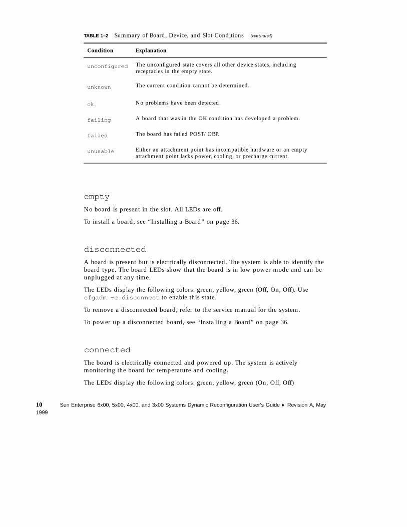
TABLE 1–2 Summary of Board, Device, and Slot Conditions (continued)
Condition Explanation
unconfigured The unconfigured state covers all other device states, includingreceptacles in the empty state.
unknown The current condition cannot be determined.
ok No problems have been detected.
failing A board that was in the OK condition has developed a problem.
failed The board has failed POST/OBP.
unusable Either an attachment point has incompatible hardware or an emptyattachment point lacks power, cooling, or precharge current.
empty
No board is present in the slot. All LEDs are off.
To install a board, see “Installing a Board” on page 36.
disconnected
A board is present but is electrically disconnected. The system is able to identify theboard type. The board LEDs show that the board is in low power mode and can beunplugged at any time.
The LEDs display the following colors: green, yellow, green (Off, On, Off). Usecfgadm -c disconnect to enable this state.
To remove a disconnected board, refer to the service manual for the system.
To power up a disconnected board, see “Installing a Board” on page 36.
connected
The board is electrically connected and powered up. The system is activelymonitoring the board for temperature and cooling.
The LEDs display the following colors: green, yellow, green (On, Off, Off)
10 Sun Enterprise 6x00, 5x00, 4x00, and 3x00 Systems Dynamic Reconfiguration User’s Guide ♦ Revision A, May1999
Use cfgadm -c connect to enable this state. To remove a connected board, see“Removing a Board” on page 27. To use a connected board, see “Installing a Board”on page 36.
configured
Devices on the board are fully initialized and may be mounted or configured for use.The LEDs show the normal running pattern.
The LEDs display the following colors: On, Off, Flash
Use cfgadm -c configure to enable this state.
To remove a configured board, see “Removing a Board” on page 27.
unconfigured
The unconfigured state covers all other device states, including receptacles in theempty state. The LED pattern is the same as for the connected receptacle state.
The LEDs display the following colors: green, yellow, green (On, Off, Off)
Use cfgadm -c unconfigure to enable this state.
To remove an unconfigured board, see “Removing a Board” on page 27.
To use an unconfigured board, see “Installing a Board” on page 36.
unknown
The current condition cannot be determined. This situation results either when a newboard is inserted in a running system, or a board is placed on the disabled board listprior to a reboot. A transition to a connected receptacle state will change anattachment point condition from unknown to either OK or Failed.
To use an unknown board, see “Installing a Board” on page 36.
ok
No problems have been detected. This condition can only occur after a board hasbeen connected. This condition will persist either until the board is physicallyremoved, or a problem is detected. An ok condition requires correct hardwarecompatibility, correct firmware revision, adequate power, adequate cooling, andadequate precharge.
To remove an ok board, see “Removing a Board” on page 27.
Overview 11
failing
A failing condition can only occur when a board that was in the OK conditiondevelops a problem. For example, the board has begun to overheat. This conditionwill be displayed until the problem is corrected or the attachment point isdisconnected.
To remove a failing board, see “Removing a Board” on page 27.
To correct an overheating condition, see the system service manual.
failed
The board has failed POST/OBP. A failed condition may occur either during bootupor after a failed connect attempt. This condition is considered uncorrectable and willpersist until the board is physically removed. For a failed attachment point condition,the receptacle state should never transition beyond disconnected.
To remove a failed board, see “Removing a Board” on page 27.
unusable
Either an attachment point has incompatible hardware, or an empty attachment pointlacks power, cooling, or precharge current. An unusable condition is correctable. Thiscondition is caused by one of the following events:
1. Inadequate cooling in a slot
2. Power is detected in an empty slot
3. A disconnected board has inadequate cooling, inadequate power, or unsupportedhardware
4. Firmware has detected a problem either during bootup or when a board isinserted
To remove a board from an unusable slot, see “Removing a Board” on page 27.
To correct overheating conditions in the slot, refer to the system service manual.
Naming Conventions for Memory Banks and CPUNumbersThis section explains the numbering of memory banks and CPUs used in thecfgadm status display.
12 Sun Enterprise 6x00, 5x00, 4x00, and 3x00 Systems Dynamic Reconfiguration User’s Guide ♦ Revision A, May1999
Memory Bank ac NumbersThe cfgadm status report lists memory banks in the order of their respective boardaddress controller numbers (ac0 , ac1 , ac2 , and so forth). Note that the ac numbersare not listed in the order of their physical board slot numbers, but in thechronological order in which the CPU/memory boards were inserted into thesystem. Thus, if the second CPU/memory board is already in slot 7, and you nowinstall a third CPU/memory board in slot 4, a cfgadm status report would list thethird CPU/memory board (ac2 ) after the second CPU/memory board, even thoughthe third CPU/memory board is in a lower-numbered physical slot.
CPU NumbersThe CPUs are identified by numbers based on the board number. The first CPUnumber is equal to twice the board number (2*n). The second CPU number is twicethe board number, plus one (2*n + 1).
For example, for board 3 the CPUs are 6 and 7. To see the CPU information for board3, specify CPUs 6 and 7 in the psrinfo command:
# psrinfo 6 76 on-line since 01/10/99 18:00:567 on-line since 01/10/99 18:01:01
Attachment PointAn attachment point is a collective term for a board and its card cage slot.
DR can display the status of the slot, the board, and the attachment point. The DRdefinition of a board also includes the devices connected to it, so the term occupantrefers to the combination of board and attached devices.
� A slot (also called a receptacle) may have the ability to electrically isolate theoccupant from the host machine. That is, the software can put a single slot intolow-power mode.
� Receptacles can be named according to slot numbers or can be anonymous (forexample, a SCSI chain). To obtain a list of all available logical attachment points,use the -l option with the cfgadm command.
� An occupant I/O board includes any external storage devices connected byinterface cables.
There are two types of system names for attachment points:
� A physical attachment point describes the software driver and location of the cardcage slot. An example of a physical attachment point name is:
Overview 13
/devices/central@1f,0/fhc@0,f8800000/clock-board@0,900000:sysctrl,slot0
� A logical attachment point is an abbreviated name created by the system to refer tothe physical attachment point:
sysctrl0:slot0
Tip - Note that in the term sysctrl0 , “l” is a letter and “0” is zero.
DetachabilityFor a device to be detachable:
� The device driver must support DDI_DETACH.
� Critical resources must be redundant or accessible through an alternate pathway.CPUs and memory banks can be redundant critical resources. Disk drives areexamples of critical resources that can be accessible through an alternate pathway(through an alternate I/O board).
Some boards cannot be detached. For example, if a system has only one CPU board,that CPU board cannot be detached. An I/O board is not detachable if it controls aboot drive (unless Alternate Pathing is installed on the system, in which case youcan switch control of the boot drive to an alternate I/O board).
In the current revision of the software, the lowest-numbered CPU/memory boardcannot be detached. In the verbose version of the status display (cfgadm -v ) theseboards are identified as “non-detachable”. For example, in Code Example 1–2, theboards in slot 0 and slot 1 are listed as non-detachable.
If there is no alternate pathway for an I/O board, you can:
� Put the disk chain on a separate I/O board. The secondary I/O board can then bedetached.
� Add a second path to the device through a second I/O board. The I/O board canbe detached (using Alternate Pathing software to switch access through thealternate board) without losing access to the secondary disk chain.
Conditions and StatesA state is the operational status of either a receptacle (slot) or an occupant (board).
A condition is the operational status of an attachment point.
The cfgadm program can display 10 types of states and conditions. See Table 1–2.
14 Sun Enterprise 6x00, 5x00, 4x00, and 3x00 Systems Dynamic Reconfiguration User’s Guide ♦ Revision A, May1999
Note - For a receptacle procedure to be valid, the receptacle must transition insequence through all three states (empty, disconnected, connected) or in the reversesequence (connected, disconnected, empty).
Connection and ConfigurationThere are four main types of operations related to boards:
Connection—in this operation, the slot provides power to the board and beginsmonitoring the board temperature. For I/O boards, the connection operation isincluded in the configuration operation (see below). A connection involves a delaythat can last up to approximately one minute. The actual time depends on the typeof board and the number of boards in the system.
Configuration—the operating environment assigns functional roles to a board andloads device drivers for the board and for devices attached to the board.
Unconfiguration—the system detaches a board logically from the operatingenvironment and takes the associated device drivers offline. Environmentalmonitoring continues, but any devices on the board are not available for system use.
Disconnection—the system stops monitoring the board and power to the slot isturned off.
If a system board is in use, before powering it off and removing it, stop its use andunconfigure it. After a new or upgraded system board is inserted and powered on,connect its attachment point and configure it for use by the operating environment.
cfgadm can connect and configure (or unconfigure and disconnect) in a singlecommand, but if necessary, each operation (connection, configuration,unconfiguration, or disconnection) can be performed separately.
Hot-Plug HardwareHot-plug boards and modules have special connectors that supply electrical power tothe board or module before the data pins make contact. Boards and devices that donot have hot-plug connectors cannot be inserted or removed while the system isrunning.
I/O boards and CPU/memory boards used in Enterprise x000 and x500 systems arehot-plug devices. Some devices, such as the clock board and peripheral power supply(PPS), are not hot-plug modules and cannot be removed while the system is running.
Overview 15
QuiescenceDuring an unconfigure/disconnect operation on a system board with non-pageableOpenBootTM PROM (OBP) or kernel memory, the operating environment is brieflypaused, which is known as operating environment quiescence. All operatingenvironment and device activity on the backplane must cease for a few secondsduring a critical phase of the operation.
To quiesce a system and test for DR-compatible drivers, see “Testing forSuspend-Safe Drivers” on page 26.
Before it can achieve quiescence, the operating environment must temporarilysuspend all processes, CPUs, and device activities. If the operating environmentcannot achieve quiescence, it displays the reasons, which may include the following:
� A user thread did not suspend.
� Real-time processes are running.
� A device exists that cannot be paused by the operating environment.
The conditions that cause processes to fail to suspend are generally temporary.Examine the reasons for the failure. If the operating environment encountered atransient condition—a failure to suspend a process—you can try the operation again.
Note - The screen, mouse, and keyboard are not operational while the system issuspended, but you regain control of these devices after the system resumesoperation.
Suspend-Safe and Suspend-Unsafe DevicesA suspend-safe device is one that does not access memory or interrupt the systemwhile the operating environment is in quiescence. A driver is suspend-safe if itsupports operating environment quiescence (suspend/resume). A suspend-savedriver also guarantees that when a suspend request is successfully completed, thedevice that the driver manages will not attempt to access memory, even if the deviceis open when the suspend request is made.
Suspend-safe drivers provide the ability to:
� Stop user threads.
� Execute the DDI_SUSPENDcall in each device driver.
� Stop the clock.
� Stop the CPUs.
A suspend-unsafe device allows a memory access or a system interruption while theoperating environment is in quiescence.
The operating environment refuses a quiescence request if a suspend-unsafe device isopen. To manually suspend the device, you may have to close the device by killing
16 Sun Enterprise 6x00, 5x00, 4x00, and 3x00 Systems Dynamic Reconfiguration User’s Guide ♦ Revision A, May1999
the processes that have it open, by asking users not to use the device, or bydisconnecting the cables. For example, if a device that allows asynchronousunsolicited input is open, you can disconnect its cables prior to activating operatingenvironment quiescence and reconnect them after the operating environmentresumes. This action prevents traffic from arriving at the device and, thus, the devicehas no reason to access the backplane.
Tape Devices
The sequential nature of tape devices prevents them from being reliably suspendedin the middle of an operation, and then resumed. Therefore, all tape drivers aresuspend-unsafe. Before executing an operation that activates operating environmentquiescence, make sure all tape devices are closed or not in use.
Discussion of Board or DeviceInstallationThe installation of a new board involves the connection and configuration operationsdescribed below. If the board is intended to be a spare board, it must additionally bedisabled now, so that you can enable it when you want to use it.
Note - This section does not contain actual procedures. Service procedures begin inChapter 2.
To install a board, see “Installing a Board” on page 36.
To add a storage device to an existing board, see “Adding Storage Devices” on page42.
Connecting a BoardAfter a board is physically inserted into the card cage, a logical connection must bemade. For I/O boards the configuration step automatically connects the board. ForCPU/memory boards, the connect operation is not included in the configuration step.
The syntax for a board connection is:
cfgadm -c connect sysctrl0:slot number
The term sysctrl0:slot number is the logical attachment point identification (thesystem name for the board), which can be found in the cfgadm status display.
Overview 17
During the connection process, there is a delay of from 15 seconds to more than aminute before the prompt returns. The length of the delay depends on the type ofboard and the size and complexity of the system. The system tests the board duringthis delay.
The states and conditions for the attachment point before a board is inserted are:
� Receptacle state—Empty
� Occupant state—Unconfigured
� Condition—Unknown
After a board is physically inserted, the states and conditions are:
� Receptacle state—Disconnected
� Occupant state—Unconfigured
� Condition—Unknown
After the attachment point is logically connected, the states and conditions are:
� Receptacle state—Connected
� Occupant state—Unconfigured
� Condition—OK
Now the system is aware of the board, but not the usable devices that reside on theboard. Temperature is monitored, and power and cooling affect the attachment pointcondition.
Configuring a BoardFor I/O boards the configure operation on a disconnected board will alsoautomatically include the connect operation.
Use the cfgadm command to configure a CPU/memory board:
# cfgadm -c configure sysctrl0:slot number
The states and conditions for a configured attachment point are:
� Receptacle state—Connected
� Occupant state—Configured
� Condition—OK
Now the system is also aware of the usable devices which reside on the board andall devices may be mounted or configured for use.
If the configure operation fails for any reason, the states and conditions will stilltransition to configured. This creates a special situation where the board is partially
18 Sun Enterprise 6x00, 5x00, 4x00, and 3x00 Systems Dynamic Reconfiguration User’s Guide ♦ Revision A, May1999
configured. In this situation, only an unconfigure operation is allowed. A furtherattempt to reconfigure the partial configuration is not permitted.
Using a Board as a SpareA working board can be kept in the system for use as a spare. To prepare the boardfor this use, enter the name of the board in the disabled board list. This prevents theboard from being used when the system is turned on or rebooted. See “Disabling aBoard” on page 43.
To use a spare board, see “Enabling Spare Boards” on page 44.
Enabling an Unconfigured BoardA running system may contain one or more unconfigured boards. That is, the boardsare not being used by the system. These unconfigured boards may have been:
� Plugged into the system after the system was booted
� Disabled (as described the previous section)
� Previously unconfigured
To enable a board, use the configure option described in “Configuring a Board ” onpage 18.
Addition of Storage DevicesTo add a storage device, see “Adding Storage Devices” on page 42.
Discussion of Board RemovalThe removal of a board requires the devices attached to the board be idled, followedby the unconfiguration and disconnection of the board, as described below.
Note - This section does not contain actual procedures. Service procedures begin inChapter 2.
The steps include:
1. Preparing the devices on the board.
Overview 19
2. Unconfiguring the board.
Memory Device PreparationDynamic reconfiguration of interleaved memory is not currently supported. Todetermine if interleaved memory is used in the system, use the prtdiag or cfgadmcommands. Memory boards and CPU/memory boards can be dynamicallyreconfigured if memory on the boards is not interleaved.
I/O and Network Device PreparationA board with vital system resources cannot be detached unless alternate resourcesare available on another board. A boot disk is an example of a vital system resource.
A board hosting non-vital system resources can be unconfigured whether or notthere are alternate paths to the resources. All its file systems must be unmounted andits swap partitions must be deleted. You may have to kill processes that have openfiles or devices, or place a hard lock on the file systems (using lockfs(1M) ) beforeunmounting the file systems. All I/O device drivers must be detachable.
The system swap space should be configured as multiple partitions on disks attachedto controllers hosted by different boards. With this kind of configuration, a particularswap partition is not a vital resource because swap partitions can be added anddeleted dynamically. See swap(1M) for more information.
Note - When memory or disk swap space is detached, there must be enoughmemory or swap disk space remaining in the machine to accommodate currentlyrunning programs.
I/O Board Unconfiguration
Preparation of an I/O Board for RemovalBefore the unconfigure operation can be completed, you must manually terminateusage of all I/O devices on the board, including network interfaces. If AlternatePathing is installed on your system, switch all I/O functions from the board toalternate I/O boards.
20 Sun Enterprise 6x00, 5x00, 4x00, and 3x00 Systems Dynamic Reconfiguration User’s Guide ♦ Revision A, May1999
Note - To identify the components that are on the board to be unconfigured, use theprtdiag(1M) , ifconfig(1M) , mount(1M) , ps(1) , or swap(1M) commands. Theprtdiag(1M) command provides some information, but is less informative.
Termination of Network DevicesUnconfiguring a board does not automatically terminate use of all network interfaceson the board. You must manually terminate the use of each interface.
You cannot unconfigure any interface that fits the following conditions. In thesecases, the unconfigure operation fails with an error message.
� The network interface is the primary network interface for the machine. That is,the IP address of the interface corresponds to the network interface namecontained in the file /etc/nodename . Halting the primary network interface forthe machine prevents network information name services from operating, whichresults in the inability to make network connections to remote hosts usingapplications such as ftp(1) , rsh(1) , rcp(1) , rlogin(1) . NFS client andserver operations are also affected.
� The interface is the active alternate for an Alternate Pathing (AP) meta devicewhen the AP meta device is plumbed. Interfaces used by the AP system shouldnot be the active path when the board is being unconfigured. Manually switch theactive path to one that is not on the board being unconfigured. If no such pathexists, manually execute the ifconfig down and ifconfig unplumb commandson the AP interface. (To manually switch an active path, use the apconfig(1M)command.)
Discussion of Board and DeviceReplacement or ModificationFor the procedure to replace a board, see “Installing a Board” on page 36.
For the procedure to add an interface to a board, see “Adding Storage Devices” onpage 42.
Replacement SequenceA number of conditions must be satisfied before a system board can be added to orremoved from a system that is under power. For example, the peripheral powersupply (PPS) module must be working properly because the PPS supplies precharge
Overview 21
current that allows a system board to be safely inserted or removed. A power andcooling module (PCM) must also be working properly in order to supply electricalcurrent and cooling air to system boards.
For these reasons, before you add or replace a system board in Enterprise x000 andx500 servers, first replace any defective PPS or PCM modules.
Discussion of System ReconfigurationThis section discusses reconfiguring your system after you have configured orunconfigured a system board.
When to ReconfigureIn the current version of the software, you might need to reconfigure the systemunder several conditions, including:
� Board addition—when adding a board, you must execute the reconfigurationsequence to configure the I/O devices associated with the board.
� Board removal—if you remove a board that is not to be replaced, you may (but donot have to) execute the reconfiguration sequence to clean up the /dev links fordisk devices.
� Board replacement—if you remove a board and then insert it into a different slot,or replace a board with another board that has different I/O devices, you mustexecute the reconfiguration sequence to configure the I/O devices associated withthe board. However, if you replace a board with another board that hosts the sameset of I/O devices, inserting the replacement into the same slot, you may not needto execute the reconfiguration sequence. But be sure to insert a replacement intothe same slot that was vacated to retain the original /dev link names.
These limitations are expected to be removed in future versions of the software.
I/O Device ReconfigurationThe reconfiguration sequence is the same as the Solaris reconfiguration bootsequence (boot -r ):
drvconfig; devlinks; disks; ports; tapes;
22 Sun Enterprise 6x00, 5x00, 4x00, and 3x00 Systems Dynamic Reconfiguration User’s Guide ♦ Revision A, May1999
When the reconfiguration sequence is executed after a board is configured, devicepath names not previously seen by the system are entered into the/etc/path_to_inst file. The same path names are also added to the /deviceshierarchy and links to them are created in the /dev directory.
Disk Controller Renumbering During aReconfiguration
Caution - The disk controller number is part of the /dev link name used to accessthe disk. If that number changes during the reconfiguration sequence, the /dev linkname also changes. This change may affect file system tables and software, such asSolstice
TM
DiskSuiteTM
, which uses the /dev link names. Update /etc/vfstab filesand execute other administrative actions necessary due to the changes in the /devlink names.
When the reconfiguration sequence is executed after a board is unconfigured ordisconnected, the /dev links for all the disk partitions on that board may be deleted.The remaining boards retain their current numbering. Disk controllers on a newlyinserted board are assigned the next available lowest number by disks(1M) .
The disks(1m) utility creates symbolic links in the /dev/dsk and /dev/rdskdirectories pointing to the actual special disk device files under the /devicesdirectory tree. These entries take the form /dev/dsk/c xt xdxsx where:
� cx is the disk controller number
� t x corresponds to the disk target number, in most cases
� dx refers to the logical unit number
� sx is the partition number
Removing boards that contain one or more disk controllers prompts the disks(1m)utility to examine entries in /dev/dsk and /dev/rdsk . These entries list the disksattached to the removed controller(s). The disks(1m) utility discovers references todisconnected devices have been removed from /dev/dsk and /dev/rdsk . Thisremoval action makes the logical controller numbers available for re-use. This re-useof controller numbers can lead to confusion when unexpected controller numbers areassigned to disk controllers that are added to the system.
Overview 23

24 Sun Enterprise 6x00, 5x00, 4x00, and 3x00 Systems Dynamic Reconfiguration User’s Guide ♦ Revision A, May1999
CHAPTER 2
Procedures
These procedures are covered in this chapter:
� “SPARC: Displaying PROM Versions” on page 25
� “Testing for Suspend-Safe Drivers” on page 26
� “Enabling Dynamic Reconfiguration” on page 27
� “Removing a Board” on page 27
� “Removing Boards That Use Detach-Unsafe Drivers” on page 34
� “Temporarily Unconfiguring a Board ” on page 35
� “Installing a Board” on page 36
� “Adding Storage Devices” on page 42
� “Preparing a Spare Board” on page 43
Note - The screen, mouse, and keyboard are not operational at times when DRmomentarily suspends the system, but you regain control of these devices whenthe system resumes operations.
SPARC: Displaying PROM Versions1. To see your current PROM version, enter .version and banner at the ok
prompt. Your display may be similar to the following:
25
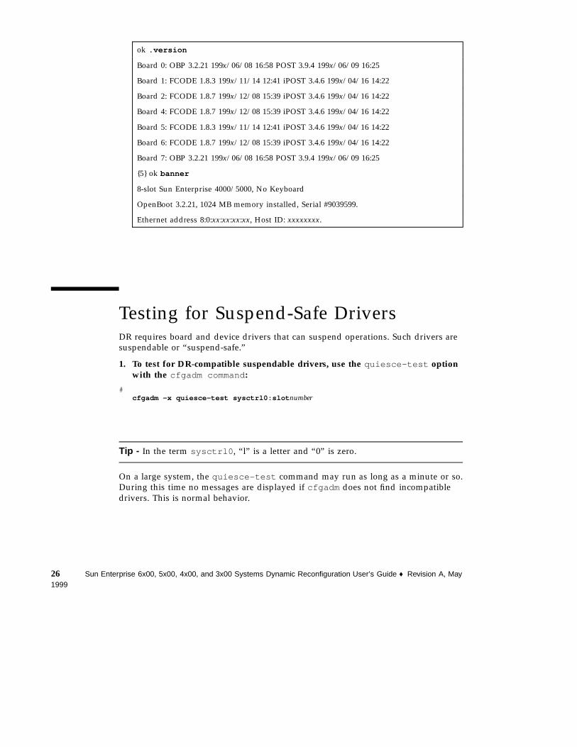
ok .version
Board 0: OBP 3.2.21 199x/06/08 16:58 POST 3.9.4 199x/06/09 16:25
Board 1: FCODE 1.8.3 199x/11/14 12:41 iPOST 3.4.6 199x/04/16 14:22
Board 2: FCODE 1.8.7 199x/12/08 15:39 iPOST 3.4.6 199x/04/16 14:22
Board 4: FCODE 1.8.7 199x/12/08 15:39 iPOST 3.4.6 199x/04/16 14:22
Board 5: FCODE 1.8.3 199x/11/14 12:41 iPOST 3.4.6 199x/04/16 14:22
Board 6: FCODE 1.8.7 199x/12/08 15:39 iPOST 3.4.6 199x/04/16 14:22
Board 7: OBP 3.2.21 199x/06/08 16:58 POST 3.9.4 199x/06/09 16:25
{5} ok banner
8-slot Sun Enterprise 4000/5000, No Keyboard
OpenBoot 3.2.21, 1024 MB memory installed, Serial #9039599.
Ethernet address 8:0:xx:xx:xx:xx, Host ID: xxxxxxxx.
Testing for Suspend-Safe DriversDR requires board and device drivers that can suspend operations. Such drivers aresuspendable or “suspend-safe.”
1. To test for DR-compatible suspendable drivers, use the quiesce-test optionwith the cfgadm command :
#cfgadm -x quiesce-test sysctrl0:slot number
Tip - In the term sysctrl0 , “l” is a letter and “0” is zero.
On a large system, the quiesce-test command may run as long as a minute or so.During this time no messages are displayed if cfgadm does not find incompatibledrivers. This is normal behavior.
26 Sun Enterprise 6x00, 5x00, 4x00, and 3x00 Systems Dynamic Reconfiguration User’s Guide ♦ Revision A, May1999
Enabling Dynamic ReconfigurationIn the /etc/system file, two variables must be set to enable dynamicreconfiguration and an additional variable must be set to enable the removal ofCPU/memory boards.
1. Log in as superuser.
2. To enable dynamic reconfiguration, edit the /etc/system file and add thefollowing lines:
set pln:pln_enable_detach_suspend=1set soc:soc_enable_detach_suspend=1
3. To enable the removal of a CPU/memory board, edit the /etc/system file andadd this line:
set kernel_cage_enable=1
Setting this variable enables the memory unconfiguration operation.
4. Reboot the system to put the changes into effect.
Removing a BoardThere are two separate procedures in this section:
� “Removing a CPU/Memory Board” on page 27“Removing a CPU/MemoryBoard” on page 27
� “Removing an I/O Board” on page 30
Removing a CPU/Memory BoardThe memory modules on a CPU/memory board can be shared by other CPU/memory boards. It is therefore necessary to halt all use of memory modules on aboard before the board can be removed from a system configuration.
Procedures 27
Note - The CPU/memory board cannot be removed if (1) it contains interleavedmemory or (2) if it is listed in the cfgadm status report (cfgadm -scols=ap_id:type:info ) as “non-detachable” or “permanent”.
1. Log in as root.
2. Use the cfgadm command to determine the system name for the CPU/memoryboard.
Code Example 2–1 shows the cfgadm output for a typical Sun Enterprise 6x00system.
For the example in this procedure, the board is ac1 , which has one memory bank(bank1).
3. Stop all activity in the memory modules on the board.
This step halts all accesses by other CPU/memory boards and prevents anyfurther use until the board is replaced.
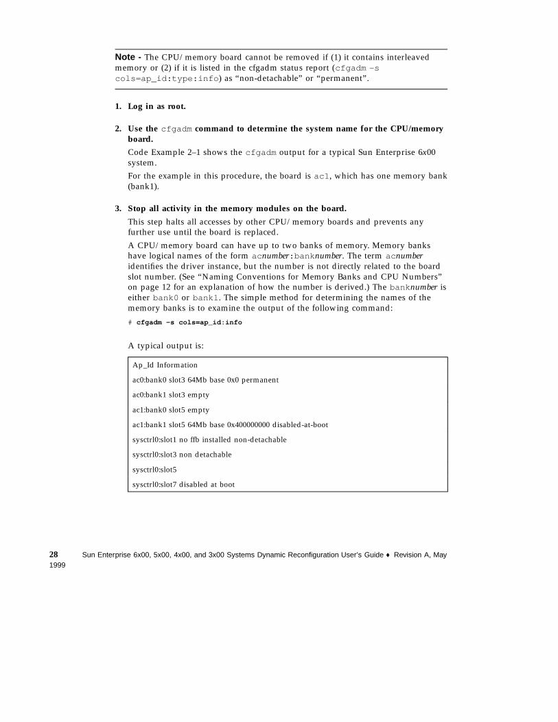
A CPU/memory board can have up to two banks of memory. Memory bankshave logical names of the form ac number:bank number. The term ac numberidentifies the driver instance, but the number is not directly related to the boardslot number. (See “Naming Conventions for Memory Banks and CPU Numbers”on page 12 for an explanation of how the number is derived.) The bank number iseither bank0 or bank1 . The simple method for determining the names of thememory banks is to examine the output of the following command:
# cfgadm -s cols=ap_id:info
A typical output is:
Ap_Id Information
ac0:bank0 slot3 64Mb base 0x0 permanent
ac0:bank1 slot3 empty
ac1:bank0 slot5 empty
ac1:bank1 slot5 64Mb base 0x400000000 disabled-at-boot
sysctrl0:slot1 no ffb installed non-detachable
sysctrl0:slot3 non detachable
sysctrl0:slot5
sysctrl0:slot7 disabled at boot
28 Sun Enterprise 6x00, 5x00, 4x00, and 3x00 Systems Dynamic Reconfiguration User’s Guide ♦ Revision A, May1999
This output shows two populated banks of memory: ac0:bank0 is on the boardin slot3 (sysctrl0:slot3 ) and ac1:bank is on the board in slot 5(sysctrl0:slot5 ).
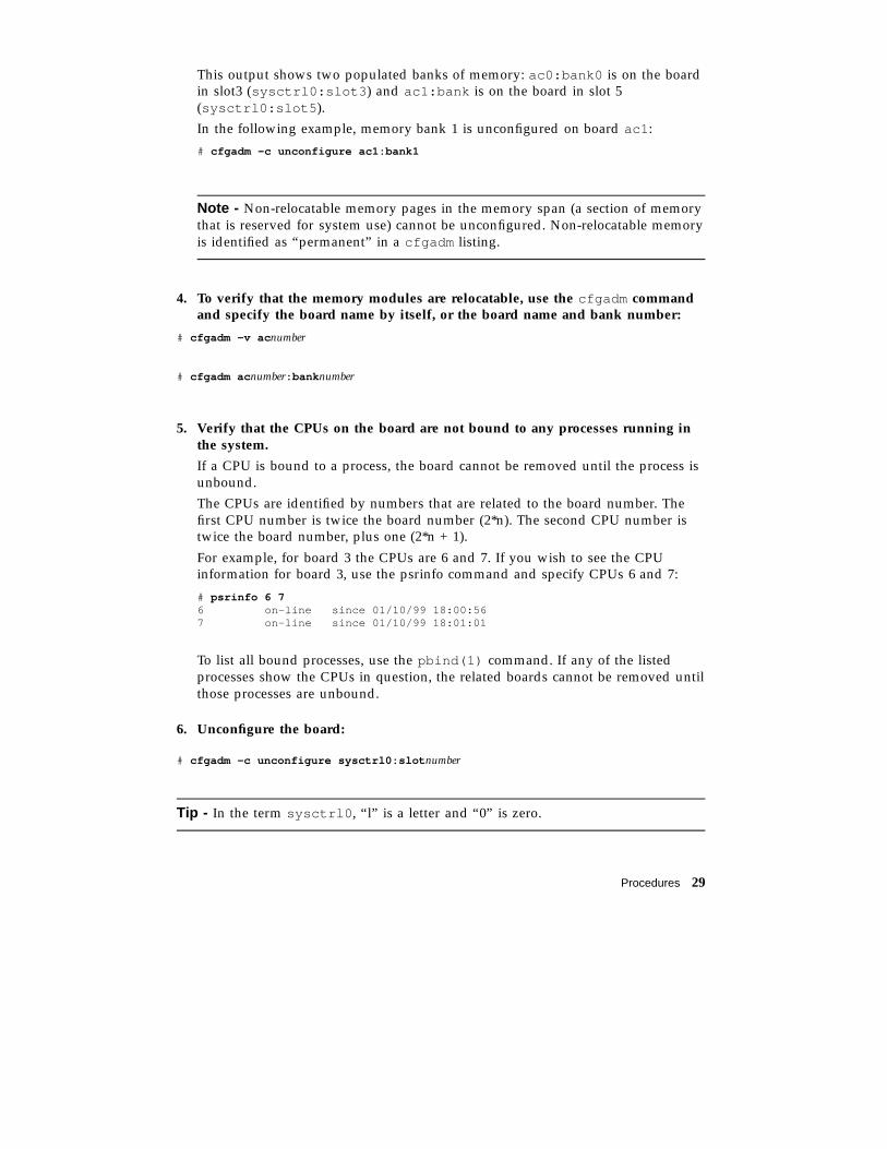
In the following example, memory bank 1 is unconfigured on board ac1 :
# cfgadm -c unconfigure ac1:bank1
Note - Non-relocatable memory pages in the memory span (a section of memorythat is reserved for system use) cannot be unconfigured. Non-relocatable memoryis identified as “permanent” in a cfgadm listing.
4. To verify that the memory modules are relocatable, use the cfgadm commandand specify the board name by itself, or the board name and bank number:
# cfgadm -v ac number
# cfgadm ac number:bank number
5. Verify that the CPUs on the board are not bound to any processes running inthe system.
If a CPU is bound to a process, the board cannot be removed until the process isunbound.
The CPUs are identified by numbers that are related to the board number. Thefirst CPU number is twice the board number (2*n). The second CPU number istwice the board number, plus one (2*n + 1).
For example, for board 3 the CPUs are 6 and 7. If you wish to see the CPUinformation for board 3, use the psrinfo command and specify CPUs 6 and 7:
# psrinfo 6 76 on-line since 01/10/99 18:00:567 on-line since 01/10/99 18:01:01
To list all bound processes, use the pbind(1) command. If any of the listedprocesses show the CPUs in question, the related boards cannot be removed untilthose processes are unbound.
6. Unconfigure the board:
# cfgadm -c unconfigure sysctrl0:slot number
Tip - In the term sysctrl0 , “l” is a letter and “0” is zero.
Procedures 29
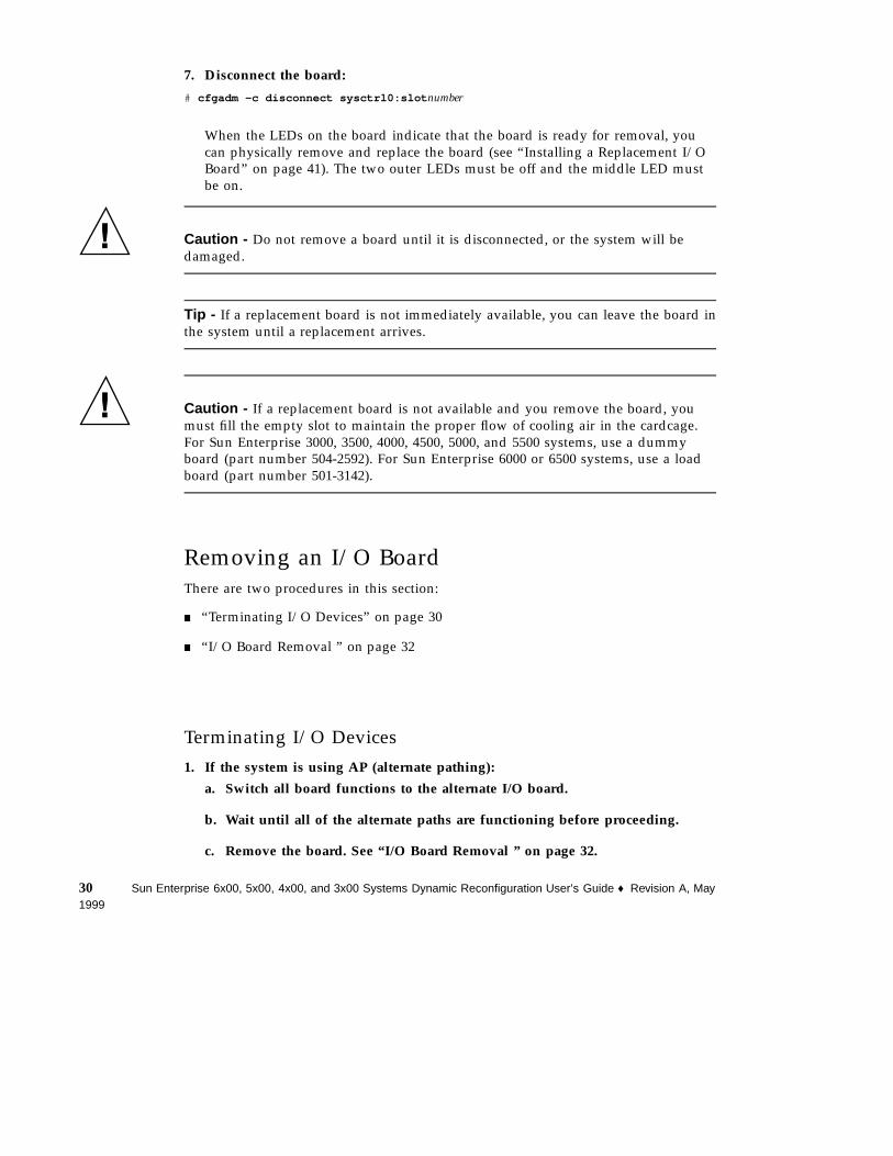
7. Disconnect the board:
# cfgadm -c disconnect sysctrl0:slot number
When the LEDs on the board indicate that the board is ready for removal, youcan physically remove and replace the board (see “Installing a Replacement I/OBoard” on page 41). The two outer LEDs must be off and the middle LED mustbe on.
Caution - Do not remove a board until it is disconnected, or the system will bedamaged.
Tip - If a replacement board is not immediately available, you can leave the board inthe system until a replacement arrives.
Caution - If a replacement board is not available and you remove the board, youmust fill the empty slot to maintain the proper flow of cooling air in the cardcage.For Sun Enterprise 3000, 3500, 4000, 4500, 5000, and 5500 systems, use a dummyboard (part number 504-2592). For Sun Enterprise 6000 or 6500 systems, use a loadboard (part number 501-3142).
Removing an I/O BoardThere are two procedures in this section:
� “Terminating I/O Devices” on page 30
� “I/O Board Removal ” on page 32
Terminating I/O Devices1. If the system is using AP (alternate pathing):
a. Switch all board functions to the alternate I/O board.
b. Wait until all of the alternate paths are functioning before proceeding.
c. Remove the board. See “I/O Board Removal ” on page 32.
30 Sun Enterprise 6x00, 5x00, 4x00, and 3x00 Systems Dynamic Reconfiguration User’s Guide ♦ Revision A, May1999
2. If AP is not available, warn all users to stop using the functions that the boardprovides.
3. Terminate all usage of devices on the board.
All I/O devices must be closed before they can be unconfigured. Ensure that anynetworking interfaces on the board are not in use. All storage devices attached tothe board should be unmounted and closed. See “I/O Board Unconfiguration” onpage 20.
a. To identify the components that are on the board to be unconfigured, usethe ifconfig , mount , df , or swap commands.
b. To see which processes have these devices open, use the fuser(1M)command.
c. Ensure that any networking interfaces on the board are not in use. Allstorage devices attached to the board should be unmounted and closed.
Note - DR does not automatically terminate network use or close devices.There currently is no way to ensure that the use of the network remainsterminated or that all devices remain closed. Other clients may remount thembetween the time of the unmount and the unconfigure operations.
4. Unmount file systems, including Solstice DiskSuite meta-devices that have aboard resident partition, (for example: umount / partition)
5. Remove Solstice DiskSuite or Alternate Pathing databases from board-residentpartitions. The location of Solstice DiskSuite or Alternate Pathing databases ischosen by the user and can be changed.
6. Remove any private regions used by Sun Enterprise Volume ManagerTM
. Thevolume manager by default uses a private region on each device that itcontrols, so such devices must be removed from volume manager controlbefore they can be detached.
7. If the board contains Sun RSM ArrayTM
2000 controllers, take the controllersoffline, using the rm6 or rdacutil commands.
8. Remove disk partitions from the swap configuration.
9. Either kill any process that directly opens a device or raw partition, or directsuch a process to close the open device on the board.
Procedures 31
10. If a detach-unsafe device is present on the board, close all instances of thedevice and use modunload(1M) to unload the driver. If a detach-unsafe deviceis present on the board, close all instances of the device and usemodunload(1M) to unload the driver.
Caution - Unmounting file systems may affect NFS client systems.
I/O Board Removal1. Terminate all usage of devices on the board.
See “Terminating I/O Devices” on page 30.
2. Check the status of the board:
� For a simple list containing board names, states, and conditions, enter:
# cfgadm
� For a more detailed list, enter:
# cfgadm -v
For a board removal or replacement, the states and conditions must be one of thefollowing sets:
� The board is ok:
� Receptacle state—Connected� Occupant state—Configured� Condition—OK
� The board is failing:
� Receptacle state—Connected� Occupant state—Configured� Condition—Failing
3. Unconfigure the board:
# cfgadm -c unconfigure sysctrl0:slot number
Tip - In the term sysctrl0 , “l” is a letter and “0” is zero.
For sysctrl0:slot number (the attachment point ID) use the board name thatwas listed in the status report of the previous step.
For an I/O board, the unconfigure operation normally also disconnects the board.
32 Sun Enterprise 6x00, 5x00, 4x00, and 3x00 Systems Dynamic Reconfiguration User’s Guide ♦ Revision A, May1999
4. Use the cfgadm command to confirm that the board is unconfigured.
If the unconfigure operation failed:
a. See “Removing Boards That Use Detach-Unsafe Drivers” on page 34.
b. See “Quiescence” on page 16.
c. Resolve the problem.
d. Unconfigure the board again (Step 1 on page 28).
Note - A failure of the unconfigure step results in a partially unconfiguredcondition. If this happens, attempt to unconfigure again. A configurationoperation is not permitted at this point.
5. When the board is unconfigured, you can do one of the following:
� Leave the board in the system unconfigured.
� Configure the board.
� Disconnect the board manually, if the unconfiguration operation did not do soautomatically:
# cfgadm -v -c disconnect sysctrl0:slot number
6. If you wish to remove the board from the card cage, first verify the board status.
a. Use cfgadm to verify that the board is logically disconnected.
b. Check the LEDs on the board to verify that the board is electricallydisconnected.The two outer LEDs must be off and the middle LED must be on.
After you have verified that the board is disconnected, and the peripheral powersupply is operating properly (see “Replacement Sequence ” on page 21), you canphysically remove or replace the board. For the replacement procedure, see“Installing a Board” on page 36.
If a replacement board is not available, you can leave the board in the system until areplacement arrives.
Procedures 33
Caution - If you remove a board and a replacement board is not immediatelyavailable, you must fill the empty slot to maintain the proper flow of cooling air inthe cardcage. For Sun Enterprise 3000, 3500, 4000, 4500, 5000, and 5500 systems, use adummy board (part number 504-2592). For Sun Enterprise 6000 or 6500 systems, usea load board (part number 501-3142).
Removing Boards That UseDetach-Unsafe DriversSome drivers do not yet support DR on Sun Enterprise 3x00, 4x00, 5x00, and 6x00systems. DR cannot detach these drivers, but you can remove some undetachabledrivers manually.
1. Halt all use of the device controller.
2. Halt the use of all other controllers of the same type on all boards in themachine.
The remaining controllers can be used again after the DR unconfigure operationis complete.
3. Use appropriate Unix commands to manually close all such drivers on theboard.
4. Use the modinfo(1M) command to find the module IDs of the drivers, thenuse the modunload(1M) command to unload them.
5. Disconnect the board with this command:
# cfgadm -c disconnect sysctrl0:slot number
Tip - In the term sysctrl0 , “l” is a letter and “0” is zero.
The disconnected board can be physically removed now or at a later time.
34 Sun Enterprise 6x00, 5x00, 4x00, and 3x00 Systems Dynamic Reconfiguration User’s Guide ♦ Revision A, May1999
Caution - If you remove a board and a replacement board is not immediatelyavailable, you must fill the empty slot to maintain the proper flow of cooling air inthe cardcage. For Sun Enterprise 3000, 3500, 4000, 4500, 5000, and 5500 systems, use adummy board (part number 504-2592). For Sun Enterprise 6000 or 6500 systems, usea load board (part number 501-3142).
Tip - If you cannot execute the above steps, recover the system configuration byadding the board to the disabled board list using the NVRAM settingdisabled-board-list (see Platform Notes), then reboot the system. Remove theboard at a later time.
Tip - Many third-party drivers (those purchased from vendors other than SunMicrosystems) do not yet properly support the standard Solaris software modunloadinterface. Test these driver functions during the qualification and installation phasesof any third-party device.
Temporarily Unconfiguring a BoardIf a replacement board or a filler board (a dummy board or a load board, whereapplicable) is not available, you can use DR to power down the board and leave it inplace.
1. Prepare the board with the procedures in “Discussion of Board Removal ” onpage 19.
Note - To identify the components that are on the board to be unconfigured, usethe ifconfig , mount , df , or swap commands. Another somewhat lessinformative way is to execute the prtdiag(1M) command.
2. Make sure the device is not being used.
For a board removal or replacement, the states and conditions must be one of thefollowing sets:
� The board is ok:
� Receptacle state—Connected
� Occupant state—Configured
� Condition—OK
� The board is failing:
Procedures 35
� Receptacle state—Connected� Occupant state—Configured� Condition—Failing
3. Unconfigure the attachment point occupant:
# cfgadm -v -c unconfigure sysctrl0:slot number
Tip - In the term sysctrl0 , “l” is a letter and “0” is zero.
Note - If the unconfigure step fails, the states and conditions will remain thesame as before. This creates a special situation in which the board is onlypartially unconfigured. In this situation, attempt to unconfigure again. An attemptto configure or reconfigure is not permitted at this point.
4. Disconnect the attachment point:
# cfgadm -v -c disconnect sysctrl0:slot number
5. If you do not want the attachment point to be enabled at boot:
# cfgadm -o disable-at-boot sysctrl0:slot number
Installing a BoardWhen installing a board:
� Do not use a board that is bad or suspected to be unreliable. It can crash thesystem.
� The board PROM version must support DR functionality.
� The board type and option cards must be supported by DR. Refer to the web sitefor the current list of supported hardware.
There are three separate procedures in this section;
� “Installing or Replacing a CPU/Memory Board” on page 37
36 Sun Enterprise 6x00, 5x00, 4x00, and 3x00 Systems Dynamic Reconfiguration User’s Guide ♦ Revision A, May1999
� “Installing a New I/O Board” on page 39
� “Installing a Replacement I/O Board” on page 41
Installing or Replacing a CPU/Memory Board1. If the peripheral power supply (PPS) is faulty, replace it before beginning this
procedure. The PPS must be able to supply precharge current to the board thatis being installed or removed.
2. Verify that the selected board slot can accept a board.
# cfgadm
The states and conditions should be:
� Receptacle state—Empty
� Occupant state—Unconfigured
� Condition—Unknown
or
� Receptacle state—Disconnected
� Occupant state—Unconfigured
� Condition—Unknown
3. Physically insert the board into the slot and watch for an acknowledgment onthe system console or in the system log file. The acknowledgment is of theform “name board inserted into slot3 ”.
After a CPU/memory board is inserted, the states and conditions should become:
� Receptacle state—Disconnected
� Occupant state—Unconfigured
� Condition—Unknown
Any other states or conditions are an error.
4. Configure the board:
# cfgadm -v -c configure sysctrl0:slot number
Tip - In the term sysctrl0 , “l” is a letter and “0” is zero.
There is a delay of about a minute before the message appears. The system istesting the board during the delay.
The states and conditions for a connected and configured attachment pointshould be:
Procedures 37
� Receptacle state—Connected
� Occupant state—Configured
� Condition—OK
Now the system is aware of the usable devices on the board and the devices canbe used.
5. Configure the memory devices on the board:
# drvconfig -i ac
6. Determine the system numbers of the new CPU modules. For example:
CODE EXAMPLE 2–1 Using psrinfo to List CPU Module System Numbers
# psrinfo6 on-line since 12/08/98 11:01:257 on-line since 12/08/98 11:01:2910 powered-off since 12/08/98 12:42:17
In this example, there is one new CPU module (system number 10). The modulehas not yet been enabled, so it is listed as being powered off.
Note - The system number for a CPU is calculated from the board number and isequal to twice the board number, plus 0 for CPU module 0, or 1 for CPU module1. In Code Example 2–1 system number 10 represents module 0 on board number5.
7. Enable the new CPU module or modules:
# psradm -n number number
In Code Example 2–1, there is only one CPU module (10), so the command is:
# psradm -n 10
8. Test the new memory banks:
# cfgadm -o test_type -t ac number:bank0# cfgadm -o test_type -t ac number:bank1
where test_type is one of three memory tests:
� Quick (writes a pattern of ones and zeros)
� Normal (detects specific memory address failures)
38 Sun Enterprise 6x00, 5x00, 4x00, and 3x00 Systems Dynamic Reconfiguration User’s Guide ♦ Revision A, May1999
� Extended (tests interference between memory cells)
Note - For one Gbyte of memory the test times are on the order of severalminutes (for the quick and normal tests) to more than six hours (for theextended test).
To determine the logical names of the new board, see Step 1 on page 28 in“Removing a CPU/Memory Board” on page 27.
9. Configure the new memory banks:
# cfgadm -c configure ac number:bank0# cfgadm -c configure ac number:bank1
10. Verify that the board and the memory banks are configured.
� For the CPU status, use the psrinfo or mpstat commands.
� For the memory status, use the prtconf or vmstat commands.
Installing a New I/O Board1. If the peripheral power supply (PPS) is faulty, replace it before beginning this
procedure. The PPS must be able to supply precharge current to the board thatis being installed or removed.
2. Verify that the selected board slot is ready for a board.
# cfgadm
The states and conditions should be:
� Receptacle state—Empty
� Occupant state—Unconfigured
� Condition—Unknown
or
� Receptacle state—Disconnected
� Occupant state—Unconfigured
� Condition—Unknown
3. Physically insert the board into the slot and look for an acknowledgment onthe console, such as, “name board inserted into slot3 ”.
After an I/O board is inserted, the states and conditions should become:
� Receptacle state—Disconnected
� Occupant state—Unconfigured
Procedures 39
� Condition—Unknown
Any other states or conditions should be considered an error.
4. Connect any peripheral cables and interface modules to the board.
5. Configure the board with the command:
# cfgadm -v -c configure sysctrl0:slot number
Tip - In the term sysctrl0 , “l” is a letter and “0” is zero.
This command should both connect and configure the receptacle. Verify with thecfgadm command.
The states and conditions for a connected and configured attachment pointshould be:
� Receptacle state—Connected
� Occupant state—Configured
� Condition—OK
Now the system is also aware of the usable devices which reside on the boardand all devices may be mounted or configured to be used.
If the command fails to connect and configure the board and slot (the statusshould be shown as “configured” and “ok”), do the connection and configurationas separate steps:
a. Connect the board and slot by entering:
# cfgadm -v -c connect sysctrl0:slot number
There is a delay of 15 seconds or more before the message appears. Thesystem is testing the board during the delay.The states and conditions for a connected attachment point should be:
�
� Receptacle state—Connected� Occupant state—Unconfigured� Condition—OK
Now the system is aware of the board, but not the usable devices which resideon the board. Temperature is monitored and power and cooling affect theattachment point condition.
b. Configure the board and slot by entering:
# cfgadm -v -c configure sysctrl0:slot number
The states and conditions for a configured attachment point should be:
40 Sun Enterprise 6x00, 5x00, 4x00, and 3x00 Systems Dynamic Reconfiguration User’s Guide ♦ Revision A, May1999
�
� Receptacle state—Connected
� Occupant state—Configured
� Condition—OK
Now the system is also aware of the usable devices which reside on the boardand all devices may be mounted or configured to be used.
6. Reconfigure the devices on the board by entering:
# drvconfig; devlinks; disks; ports; tapes;
The console should display a list of devices and their addresses.
7. Activate the devices on the board using commands such as mount andifconfig , as appropriate.
Installing a Replacement I/O Board1. If you are not continuing from “Removing an I/O Board” on page 30 above, use
the cfgadm command and select a card cage slot to use, but do not insert theboard yet.
2. View the configuration list and verify that the slot is unconfigured:
# cfgadm
3. Insert the board in the slot and look for an acknowledgment on the console,such as, “name board inserted into slot3 .”
4. Use the cfgadm command again to look for the system name assigned to thenew board.
5. Configure the board using the system name for the board:
# cfgadm -c configure sysctrl0:slot number
Tip - In the term sysctrl0 , “l” is a letter and “0” is zero.
There is a delay of 15 seconds or more before the message appears. The system istesting the board during the delay.
Procedures 41
6. Configure any I/O devices on the board using commands such as drvconfigand devlinks , as appropriate.
7. Activate the devices on the board using commands such as mount andifconfig , as appropriate.
Adding Storage DevicesTo add storage devices to an I/O board in the system:
1. Terminate all active use of the devices on the I/O board.
2. Unconfigure the board.
# cfgadm -c unconfigure sysctrl0:slot number
Tip - In the term sysctrl0 , “l” is a letter and “0” is zero.
3. To remove the board from the card cage:
a. Use cfgadm to verify that the board is logically disconnected.
b. Check the LEDs on the board to verify that the board is electricallydisconnected.The two outer LEDs must be off and the middle LED must be on.
c. Physically remove the board.
4. Add the storage device controller:
� For an optical controller, attach the I/O module and interface cable.
� For an SBus or PCI controller card, use the Disconnect command beforeremoving the board. Add the controller card and place the I/O board back inthe card cage.
5. Insert the board into the slot and watch for an acknowledgment on the systemconsole or in the system log file. The acknowledgment is of the form,“name board inserted into slot3 .”
After a CPU/memory board is inserted, the states and conditions should become:
42 Sun Enterprise 6x00, 5x00, 4x00, and 3x00 Systems Dynamic Reconfiguration User’s Guide ♦ Revision A, May1999
� Receptacle state—Disconnected
� Occupant state—Unconfigured
� Condition—Unknown
Any other states or conditions should be considered an error.
6. Reconfigure the board.
# cfgadm -c configure sysctrl0:slot number
There is a delay of 15 seconds or more before the prompt reappears. The systemis testing the board during the delay.
Only the Occupant state should change. The Receptacle state and conditionshould remain the same.
7. If you installed the board in a different slot, reconfigure the devices on theboard by entering:
# drvconfig; devlinks; disks; ports; tapes;
The console should display a list of devices and their addresses.
8. Activate the devices on the board using commands such as mount andifconfig , as appropriate.
Preparing a Spare BoardA working board can be disabled for later use as a spare.
Disabling a BoardThere are two methods for disabling a board. You can use an EEPROM command ora cfgadm command.
� To use the EEPROM command to disable a board:
# eeprom disabled-board-list=sysctrl0:slot number
Tip - In the term sysctrl0 , “l” is a letter and “0” is zero.
Procedures 43
� To use the cfgadm command to disable a board:
# cfgadm -c disconnect -o disable-at-boot sysctrl0:slot number
Tip - In the term sysctrl0 , “l” is a letter and “0” is zero.
Enabling Spare Boards
Enabling a Single BoardYou can enable a single disabled board immediately, or set it to be enabled at thenext boot:
1. To immediately override the disabled condition, use the force flag (-f ) with thecfgadm command:
# cfgadm -f -c connect sysctrl0:slot number
1. To enable at boot, use the enable option (-o enable-at-boot ) with thecfgadm command:
# cfgadm -o enable-at-boot -c connect sysctrl0:slot number
Tip - In the term sysctrl0 , “l” is a letter and “0” is zero.
Enabling Multiple BoardsYou can set all boards to be enabled at the next boot:
1. If you are at the system prompt, use the eeprom command to remove allboards from the disabled board list by setting the disabled-board-list variableto a null set:
# eeprom disabled-board-list=
1. If you are at the OpenBoot prompt, use this OBP command to remove allboards from the disabled board list:
OK set-default disabled-board-list
44 Sun Enterprise 6x00, 5x00, 4x00, and 3x00 Systems Dynamic Reconfiguration User’s Guide ♦ Revision A, May1999
CHAPTER 3
Troubleshooting
Troubleshooting Specific FailuresThis chapter discusses common types of failure:
� “Driver Does Not Support Dynamic Reconfiguration” on page 46
� “Unconfigure Operation Fails” on page 46
� “Configure Operation Fails” on page 50
Diagnostic MessagesThe following are examples of cfgadm diagnostic messages. (Syntax error messagesare not included here.)
cfgadm: Configuration administration not supported on this machinecfgadm: hardware component is busy, try againcfgadm: operation: configuration operation not supported on this machinecfgadm: operation: Data error: error_textcfgadm: operation: Hardware specific failure: error_textcfgadm: operation: Insufficient privilegescfgadm: operation: Operation requires a service interruptioncfgadm: System is busy, try againcfgadm: Hardware specific failure: memory delete failed: VM viability test failedcfgadm: Hardware specific failure: memory delete failed: memory operation refusedcfgadm: Hardware specific failure: memory delete failed: memory delete timeoutWARNING: Processor number number failed to offline.NOTICE: dual-sbus-soc+ board in slot 4 partially configured
45
See config_admin(3X) for additional error message detail.
Driver Does Not Support DynamicReconfigurationSome drivers do not yet support quiesce operations. A DR-compatible driver mustbe suspendable.
1. Use this command to test for suspendable drivers.
# cfgadm -x quiesce-test sysctrl0:slot number
Tip - In the term sysctrl0 , “l” is a letter and “0” is zero.
DR may not yet support some types of I/O boards in Sun Enterprise 6x00, 5x00,4x00, and 3x00 systems. For late-breaking news, refer to the Solaris 7 5/99 section atthe DR web site. See “Sun Enterprise DR Web Site” on page 2.
Unconfigure Operation FailsAn unconfigure operation can fail if:
� The devices on the board are in use.
� The affected drivers are not detachable.
CPU/Memory Board Unconfiguration FailureProblems that prevent unconfiguration for the CPU/memory board are:
� The memory banks on the board are configured (in use). See “Unable toUnconfigure a Memory Bank” on page 47.
� CPUs on the board cannot be taken off line. See “Unable to Unconfigure a CPU”on page 48.
46 Sun Enterprise 6x00, 5x00, 4x00, and 3x00 Systems Dynamic Reconfiguration User’s Guide ♦ Revision A, May1999
� The board cannot be disconnected after it is unconfigured. See “Unable toDisconnect a Board” on page 48.
Unable to Unconfigure a Memory BankTo unconfigure a memory bank, it must be possible to move the contents of thememory to the swap device, file system or some other piece of memory that is notbeing deleted.
Bank Cannot Be Reconfigured
If the unconfigure fails with the following message, this bank cannot be unconfigured:
cfgadm: Hardware specific failure: memory delete failed: non-relocatable pages in span
Some memory pages that cannot be moved.
1. To confirm that a memory page cannot be moved, use the verbose option withthe cfgadm command and look for the word “permanent” in the listing:
# cfgadm -v ac number
Not Enough Available Memory
If the unconfigure fails with one of the messages below, there would not enoughavailable memory in the system if the board is removed:
cfgadm: Hardware specific failure: memory delete failed: VM viability test failed
cfgadm: Hardware specific failure: memory delete failed: memory operation refused
1. Reduce the memory load on the system and try again. If practical, install morememory in another board slot.
Memory Demand Increased
If the unconfigure fails with the following message, the memory demand hasincreased while the unconfigure operation was proceeding:
cfgadm: Hardware specific failure: memory delete failed: memory delete timeout
Troubleshooting 47
1. Reduce the memory load on the system and try again.
Unable to Unconfigure a CPUCPU unconfiguration is part of the unconfiguration operation for a CPU/memoryboard. If the operation fails to take the CPUs offline, the following message is loggedto the console:
WARNING: Processor number failed to offline.
This failure occurs if:
� The CPU has processes bound to it.
� The CPU is the last one in a CPU set.
� The CPU is the last on-line CPU in the system.
Unable to Disconnect a BoardIt is possible to unconfigure a board and then discover that it cannot bedisconnected. The cfgadm status display lists the board as not detachable. Thisproblem occurs when the board is supplying an essential hardware service thatcannot be relocated to an alternate board.
I/O Board Unconfiguration FailureA device cannot be unconfigured or disconnected while it is in use. Many failures tounconfigure I/O boards occur because activity on the boards have not been stopped,or because an I/O device becomes active again after it has been stopped.
If Alternate Pathing is in use on the system, switch all I/O activity from the board tothe alternate I/O board.
Device BusyDisks attached to an I/O board must idled before any attempt is made tounconfigure or disconnect that board. Any attempt to unconfigure/disconnect aboard whose devices are still in use will be rejected.
If an unconfiguration operation fails because an I/O board has a busy or opendevice, the board is left only partially unconfigured. The operation sequence stoppedat the busy device.
48 Sun Enterprise 6x00, 5x00, 4x00, and 3x00 Systems Dynamic Reconfiguration User’s Guide ♦ Revision A, May1999
To regain access to the devices which were not unconfigured, the board must becompletely unconfigured and then reconfigured.
In such a case, the system will log messages similar to the following:
NOTICE: unconfiguring dual-pci board in slot 7NOTICE: dual-pci board in slot 7 partially unconfigured
1. To continue the unconfigure operation, unmount the device and retry theunconfigure operation. The board must be in the unconfigured state before youtry to reconfigure this board.
Problems with I/O DevicesAll I/O devices must be closed before they are unconfigured.
1. To see which processes have these devices open, use the fuser(1M) command.
2. Perform the following tasks for I/O devices.
� If the redundancy features of Alternate Pathing or Solstice DiskSuite mirroringare used to access a device connected to the board, reconfigure thesesubsystems so that the device or network is accessible by way of controllers onother system boards.
� Unmount file systems, including Solstice DiskSuite meta-devices that have aboard resident partition. (For example, umount/ partition).
� Remove Solstice DiskSuite or Alternate Pathing databases from board-residentpartitions. The location of Solstice DiskSuite or Alternate Pathing databases isexplicitly chosen by the user and can be changed.
� Remove any private regions used by Sun Volume Manager or Veritas VolumeManager. Volume Manager by default uses a private region on each device thatit controls, so such devices must be removed from Volume Manager controlbefore they can be detached.
� Take offline any RSM 2000 controllers on the board that is being detached,using the rm6 or rdacutil commands.
� Remove disk partitions from the swap configuration.
� Either kill any process that directly opens a device or raw partition, or direct itto close the open device on the board.
� If a detach-unsafe device is present on the board, close all instances of thedevice and use modunload(1M) to unload the driver. If a detach-unsafedevice is present on the board, close all instances of the device and usemodunload(1M) to unload the driver.
Troubleshooting 49
Caution - Unmounting file systems may affect NFS client systems.
RPC or TCP Time-out or Loss of ConnectionTime-outs occur by default after two minutes. Administrators may need to increasethis time-out value to avoid time-outs during a DR-induced operating systemquiescence, which may take longer than two minutes. Quiescing a system makes thesystem and related network services unavailable for a period of time that can exceedtwo minutes. These changes affect both the client and server machines.
Configure Operation FailsCPU/Memory Board Configuration FailureThe attempt to configure a memory bank fails if the board has been intentionallydisabled. For example:
# cfgadm -c configure ac0:bank0cfgadm: Hardware specific failure: memory is disabled at boot
1. Use the -f (force) option to overcome this problem.
# cfgadm -c configure -f ac0:bank0
I/O Board Configuration FailureA configure operation may fail because an I/O board with a device does notcurrently support hot-plugging. In such a situation, the board is now only partiallyconfigured. The operation has stopped at the unsupported device. In this situation,the board must be brought back to the unconfigured state before another configureattempt. In such a case the system will log messages similar to the following:
NOTICE: configuring dual-sbus-soc+ board in slot 4NOTICE: dual-sbus-soc+ board in slot 4 partially configured
50 Sun Enterprise 6x00, 5x00, 4x00, and 3x00 Systems Dynamic Reconfiguration User’s Guide ♦ Revision A, May1999
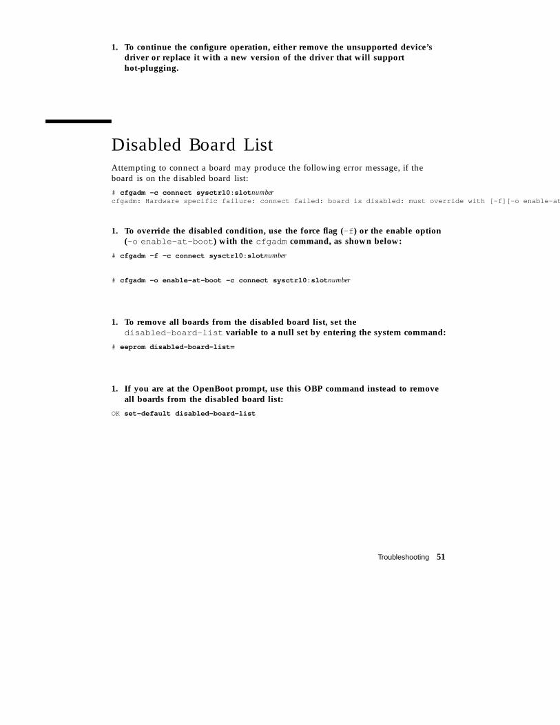
1. To continue the configure operation, either remove the unsupported device’sdriver or replace it with a new version of the driver that will supporthot-plugging.
Disabled Board ListAttempting to connect a board may produce the following error message, if theboard is on the disabled board list:
# cfgadm -c connect sysctrl0:slot numbercfgadm: Hardware specific failure: connect failed: board is disabled: must override with [-f][-o enable-a t
1. To override the disabled condition, use the force flag (-f ) or the enable option(-o enable-at-boot ) with the cfgadm command, as shown below:
# cfgadm -f -c connect sysctrl0:slot number
# cfgadm -o enable-at-boot -c connect sysctrl0:slot number
1. To remove all boards from the disabled board list, set thedisabled-board-list variable to a null set by entering the system command:
# eeprom disabled-board-list=
1. If you are at the OpenBoot prompt, use this OBP command instead to removeall boards from the disabled board list:
OK set-default disabled-board-list
Troubleshooting 51

52 Sun Enterprise 6x00, 5x00, 4x00, and 3x00 Systems Dynamic Reconfiguration User’s Guide ♦ Revision A, May1999
Glossary
AP See Alternate Pathing.ac Address controller. The cfgadm status report lists memory banks in
the order of the board address controller numbers (ac0 , ac1 , ac2 ,and so forth). Note that the ac numbers are not listed in the order oftheir physical board slot numbers, but in the chronological order inwhich the CPU/memory boards were inserted into the system.Thus, if the second CPU/memory board is already in slot 7, andyou now install a third CPU/memory board in slot 4, a cfgadmstatus report would list the third CPU/memory board (ac2 ) afterthe second CPU/memory board, even though the third CPU/memory board is in a lower-numbered physical slot.
ap_id Attachment point identifier; an ap_id specifies the type andlocation of the attachment point in the system and is unambiguous.There are two types of identifiers: physical and logical. A physicalidentifier contains a fully specified pathname, while a logicalidentifier contains a shorthand notation.
Alternate Pathing Alternate Pathing (AP) is software package that allows the use ofmultiple paths between a server and a disk array or a network. Ifone path fails, AP can ensure that the disk array or network is stillavailable through the alternate path. For example, the alternate pathcan be a second port on an interface board, or an entirely separateinterface board. See also Dynamic Reconfiguration.
Attachment point A collective term for a board and its card cage slot. Aphysical attachment point describes the software driver and locationof the card cage slot. A logical attachment point is an abbreviatedname created by the system to refer to the physical attachment point.
cfgadm command cfgadm is the primary command for dynamic reconfiguration onthe Sun Enterprise 6x00, 5x00, 4x00, and 3x00 systems. For
Glossary-53
information about the command and its options, refer to thecfgadm(1M) , cfgadm_sysctrl(1M) , and cfgadm_ac(1M) manpages. For any late-breaking news about this and related commands,refer to the Solaris 7 5/99 section at the DR web site. See “SunEnterprise DR Web Site” on page 2. For dynamic reconfigurationcommands used on the Sun Enterprise 10000 system, refer to theSun Enterprise 10000 Dynamic Reconfiguration User’s Guide.
Condition The operational status of an attachment point.
Configuration(system)
The collection of attached devices known to the system. The systemcannot use a physical device until the configuration is updated. Theoperating system assigns functional roles to a board and loadsdevice drivers for the board and for devices attached to the board.
Configuration(board)
The operating system assigns functional roles to a board and loadsdevice drivers for the board and for devices attached to the board.
Connection A board is present in a slot and is electrically connected. Thetemperature of the slot is monitored by the system.
Detachability The device driver supports DDI_DETACHand the device (such as anI/O board or a SCSI chain) is physically arranged so that it can bedetached.
Disconnection The system stops monitoring the board and power to the slot isturned off. A board in this state can be unplugged.
DR See Dynamic Reconfiguration
DynamicReconfiguration
Dynamic Reconfiguration (DR) is software that allows theadministrator to (1) view a system configuration; (2) suspend orrestart operations involving a port, storage device, or board; and (3)reconfigure the system (detach or attach hot-swappable devices suchas disk drives or interface boards) without the need to power downthe system. When DR is used with Alternate Pathing or SolsticeDiskSuite software (and redundant hardware), the server cancontinue to communicate with disk drives and networks withoutinterruption while a service provider replaces an existing device orinstalls a new device. DR supports replacement of a CPU/Memory,provided the memory on the board is not interleaved with memoryon other boards in the system.
Hot-plug Hot-plug boards and modules have special connectors that supplyelectrical power to the board or module before the data pins make
Glossary-54 Sun Enterprise 6x00, 5x00, 4x00, and 3x00 Systems Dynamic Reconfiguration User’s Guide ♦Revision A, May 1999
contact. Boards and devices that do not have hot-plug connectorscannot be inserted or removed while the system is running.
Hot swap A hot swap device has special DC power connectors and logiccircuitry that allow the device to be inserted without the necessityof turning off the system.
Logical DR A DR operation in which hardware is not physically added orremoved. An example is the deactivation of a failed board that isthen left in the slot (to avoid changing the flow of cooling air) untila replacement is available.
Physical DR A DR operation that involves the physical addition or removal of aboard. See also “Logical DR.”
Quiescence A brief pause in the operating environment to allow an unconfigureand disconnect operation on a system board with non-pageableOpenBoot PROM (OBP) or kernel memory. All operatingenvironment and device activity on the backplane must cease for afew seconds during a critical phase of the operation.
Receptacle A receiver such as a board slot or SCSI chain.
State The operational status of either a receptacle (slot) or an occupant(board).
Suspendability To be suitable for DR, a device driver must have the ability to stopuser threads, execute the DDI_SUSPENDcall, stop the clock, andstop the CPUs.
Suspend-safe A suspend-safe device is one that does not access memory orinterrupt the system while the operating system is in quiescence. Adriver is considered suspend-safe if it supports operating systemquiescence (suspend/resume). It also guarantees that when asuspend request is successfully completed, the device that the drivermanages will not attempt to access memory, even if the device isopen when the suspend request is made.
Suspend-unsafe A suspend-unsafe device is one that allows a memory access or asystem interruption while the operating system is in quiescence.
SyMON Sun Enterprise SyMON is a graphical user interface for monitoringand managing systems. The interface includes dynamicreconfiguration capability.
Glossary-55
Occupant Hardware resource such as a system board or a disk drive thatoccupies a DR receptacle or slot.
Unconfiguration The system detaches a board logically from the operating systemand takes the associated device drivers off-line. Environmentalmonitoring continues, but any devices on the board are notavailable for system use.
Glossary-56 Sun Enterprise 6x00, 5x00, 4x00, and 3x00 Systems Dynamic Reconfiguration User’s Guide ♦Revision A, May 1999