Embed Size (px)
Citation preview

Sun HPC ClusterTools™ 3.1
Administrator’s Guide
ument to: [email protected] to: [email protected]
Part No. 806-3731-10March 2000, Revision A
Send comments about this docSend comments about this doc
Sun Microsystems, Inc.901 San Antonio RoadPalo Alto, CA 94303-4900 USA650 960-1300 Fax 650 969-9131

Copyright 2000 Sun Microsystems, Inc., 901 San Antonio Road, Palo Alto, California 94303-4900 U.S.A. All rights reserved.
This product or document is protected by copyright and distributed under licenses restricting its use, copying, distribution, and decompilation.
No part of this product or document may be reproduced in any form by any means without prior written authorization of Sun and its licensors,
if any. Third-party software, including font technology, is copyrighted and licensed from Sun suppliers.
Parts of the product may be derived from Berkeley BSD systems, licensed from the University of California. UNIX is a registered trademark in
the U.S. and other countries, exclusively licensed through X/Open Company, Ltd. For Netscape Communicator™, the following notice applies:
(c) Copyright 1995 Netscape Communications Corporation. All rights reserved.
Sun, Sun Microsystems, the Sun logo, SunStore, AnswerBook2, docs.sun.com, Solaris, Sun HPC ClusterTools, Prism, Sun Performance
WorkShop Fortran, Sun Performance Library, Sun WorkShop Compilers C, Sun WorkShop Compilers C++, Sun WorkShop Compilers Fortran,
Sun Visual WorkShop, and UltraSPARC are trademarks, registered trademarks, or service marks of Sun Microsystems, Inc. in the U.S. and other
countries. All SPARC trademarks are used under license and are trademarks or registered trademarks of SPARC International, Inc. in the U.S.
and other countries. Products bearing SPARC trademarks are based upon an architecture developed by Sun Microsystems, Inc.
The OPEN LOOK and Sun™ Graphical User Interface was developed by Sun Microsystems, Inc. for its users and licensees. Sun acknowledges
the pioneering efforts of Xerox in researching and developing the concept of visual or graphical user interfaces for the computer industry. Sun
holds a non-exclusive license from Xerox to the Xerox Graphical User Interface, which license also covers Sun’s licensees who implement OPEN
LOOK GUIs and otherwise comply with Sun’s written license agreements.
RESTRICTED RIGHTS: Use, duplication, or disclosure by the U.S. Government is subject to restrictions of FAR 52.227-14(g)(2)(6/87) and FAR
52.227-19(6/87), or DFAR 252.227-7015(b)(6/95) and DFAR 227.7202-3(a).
DOCUMENTATION IS PROVIDED “AS IS” AND ALL EXPRESS OR IMPLIED CONDITIONS, REPRESENTATIONS AND WARRANTIES,
INCLUDING ANY IMPLIED WARRANTY OF MERCHANTABILITY, FITNESS FOR A PARTICULAR PURPOSE OR NON-INFRINGEMENT,
ARE DISCLAIMED, EXCEPT TO THE EXTENT THAT SUCH DISCLAIMERS ARE HELD TO BE LEGALLY INVALID.
Copyright 2000 Sun Microsystems, Inc., 901 San Antonio Road, Palo Alto, Californie 94303-4900 U.S.A. Tous droits réservés.
Ce produit ou document est protégé par un copyright et distribué avec des licences qui en restreignent l’utilisation, la copie, la distribution, et la
décompilation. Aucune partie de ce produit ou document ne peut être reproduite sous aucune forme, par quelque moyen que ce soit, sans
l’autorisation préalable et écrite de Sun et de ses bailleurs de licence, s’il y en a. Le logiciel détenu par des tiers, et qui comprend la technologie
relative aux polices de caractères, est protégé par un copyright et licencié par des fournisseurs de Sun.
Des parties de ce produit pourront être dérivées des systèmes Berkeley BSD licenciés par l’Université de Californie. UNIX est une marque
déposée aux Etats-Unis et dans d’autres pays et licenciée exclusivement par X/Open Company, Ltd. La notice suivante est applicable à
Netscape Communicator™: (c) Copyright 1995 Netscape Communications Corporation. Tous droits réservés.
Sun, Sun Microsystems, le logo Sun, AnswerBook2, docs.sun.com, Solaris , Sun HPC ClusterTools, Prism, Sun Performance WorkShop Fortran,
Sun Performance Library, Sun WorkShop Compilers C, Sun WorkShop Compilers C++, Sun WorkShop Compilers Fortran, Sun Visual
WorkShop, et UltraSPARC sont des marques de fabrique ou des marques déposées, ou marques de service, de Sun Microsystems, Inc. aux Etats-
Unis et dans d’autres pays. Toutes les marques SPARC sont utilisées sous licence et sont des marques de fabrique ou des marques déposées de
SPARC International, Inc. aux Etats-Unis et dans d’autres pays. Les produits portant les marques SPARC sont basés sur une architecture
développée par Sun Microsystems, Inc.
L’interface d’utilisation graphique OPEN LOOK et Sun™ a été développée par Sun Microsystems, Inc. pour ses utilisateurs et licenciés. Sun
reconnaît les efforts de pionniers de Xerox pour la recherche et le développement du concept des interfaces d’utilisation visuelle ou graphique
pour l’industrie de l’informatique. Sun détient une licence non exclusive de Xerox sur l’interface d’utilisation graphique Xerox, cette licence
couvrant également les licenciés de Sun qui mettent en place l’interface d’utilisation graphique OPEN LOOK et qui en outre se conforment aux
licences écrites de Sun.
CETTE PUBLICATION EST FOURNIE "EN L’ETAT" ET AUCUNE GARANTIE, EXPRESSE OU IMPLICITE, N’EST ACCORDEE, Y COMPRIS
DES GARANTIES CONCERNANT LA VALEUR MARCHANDE, L’APTITUDE DE LA PUBLICATION A REPONDRE A UNE UTILISATION
PARTICULIERE, OU LE FAIT QU’ELLE NE SOIT PAS CONTREFAISANTE DE PRODUIT DE TIERS. CE DENI DE GARANTIE NE
S’APPLIQUERAIT PAS, DANS LA MESURE OU IL SERAIT TENU JURIDIQUEMENT NUL ET NON AVENU.
PleaseRecycle

Contents
Preface xi
1. Introduction 1
Sun HPC System Hardware 2
The Cluster Runtime Environment 2
Sun HPC ClusterTools Software 3
Sun MPI and MPI I/O 3
Parallel File System 3
Prism Environment 3
Sun S3L 4
Related Tools 4
Sun Compilers 4
Cluster Console Manager 4
Switch Management Agent 5
2. Getting Started 7
Fundamental CRE Concepts 8
Cluster of Nodes 8
Partitions 8
Load Balancing 9
iii

Jobs and Processes 10
Parallel File System 10
Starting the CRE Daemons 10
Verifying Basic Functionality 11
Run mpinfo 11
Create a Default Partition 11
Verify That the CRE Executes Jobs 12
Verifying MPI Communications 12
Stopping and Restarting the CRE 13
Stopping the CRE 13
Restarting the CRE 13
3. Overview of Administration Controls 15
The CRE Daemons 15
Master Daemon tm.rdb 16
Master Daemon tm.mpmd 16
Master Daemon tm.watchd 16
Nodal Daemon tm.omd 17
Nodal Daemon tm.spmd 17
mpadmin : Administration Interface 17
Introduction to mpadmin 18
Understanding Objects, Attributes, and Contexts 19
Performing Sample mpadmin Tasks 22
Quitting mpadmin 26
Cluster Configuration File hpc.conf 27
Prepare to Edit hpc.conf 28
Create PFS I/O Servers 29
Create PFS File Systems 30
iv Sun HPC ClusterTools 3.1 Administrator’s Guide • March 2000

Set Up Network Interfaces 33
Specify MPI Options 35
Update the CRE Database 38
Enable or Disable Authentication 38
Using DES Authentication 40
Using Kerberos Version 5 Authentication 40
4. PFS Configuration and Operations 43
PFS Basics 43
PFS Components 45
I/O Daemon 46
Kernel Module 47
Proxy Daemon 47
Runtime Library 47
PFS File System Commands 48
Solaris File System Commands 48
PFS-Specific File System Commands 48
Creating a Parallel File System 49
Configure PFS File Systems and Servers 49
Start the PFS Daemons 51
Create and Mount PFS File Systems 52
Create the File System 53
Mount the File System 53
Verify That PFS File System is Mounted 53
Maintaining a PFS File System 54
Stopping the PFS File System 54
Recovering from Node or Daemon Failure 55
Notes on PFS Configuration 56
v

Authentication With Kerberos Version 5 56
Applications and I/O Processes,
Collocate or Run Separately? 57
5. Cluster Configuration Notes 59
Nodes 59
Number of CPUs 59
Memory 60
Swap Space 60
Interconnects 60
ClusterTools Internode Communication 61
Network Characteristics 63
Storage and the Parallel File System 65
PFS on SMPs and Clusters 65
PFS Using Individual Disks or Storage Arrays 65
PFS and Storage Placement 65
Balancing Bandwidth for PFS Performance 67
6. mpadmin : Detailed Description 69
mpadmin Syntax 69
Command-Line Options 70
–c command – Single Command Option 70
–f file-name – Take Input From a File 70
–h – Display Help 71
–q – Suppress Warning Message 71
–s cluster-name – Connect to Specified Cluster 71
–V – Version Display Option 71
mpadmin Objects, Attributes, and Contexts 71
mpadmin Objects and Attributes 71
vi Sun HPC ClusterTools 3.1 Administrator’s Guide • March 2000

mpadmin Contexts 72
mpadmin Command Overview 73
Types of mpadmin Commands 73
Configuration Control 74
Attribute Control 75
Context Navigation 77
Information Retrieval 79
Miscellaneous Commands 82
Additional mpadmin Functionality 85
Multiple Commands on a Line 85
Command Abbreviation 85
Using mpadmin 86
Note on Naming Partitions and Custom Attributes 86
Logging In to the Cluster 87
Customizing Cluster-Level Attributes 88
Managing Nodes and Network Interfaces 90
Managing Partitions 95
Setting Custom Attributes 102
7. hpc.conf Configuration File 105
ShmemResource Section 106
Guidelines for Setting Limits 107
Netif Section 109
Interface Names 109
Rank Attribute 110
MTU Attribute 110
Stripe Attribute 110
Protocol Attribute 111
vii

Latency Attribute 111
Bandwidth Attribute 111
MPIOptions Section 111
PFSFileSystem Section 116
Parallel File System Name 117
Server Node Hostnames 117
Storage Device Names 117
Options 118
PFSServers Section 118
Nodes 119
Options 120
HPCNodes Section 121
Propagating hpc.conf Information 121
8. Troubleshooting 123
Cleaning Up Defunct CRE Jobs 123
Removing CRE Jobs That Have Exited 123
Removing CRE Jobs That Have Not Terminated 124
Killing Orphaned Processes 125
Using Diagnostics 125
Using Network Diagnostics 125
Checking Load Averages 126
Using Interval Diagnostics 126
Interpreting Error Messages 126
Anticipating Common Problems 127
Recovering From System Failure 129
A. Cluster Console Tools 131
Launching Cluster Console Tools 132
viii Sun HPC ClusterTools 3.1 Administrator’s Guide • March 2000

Common Window 132
Hosts Menu 133
Select Hosts Dialog 133
Options Menu 135
Help Menu 135
Text Field 135
Term Windows 136
Using the Cluster Console 136
Administering Configuration Files 137
The clusters File 137
The serialports File 137
B. Using the Command Line to Install and Remove ClusterTools 3.1 139
Preparing for Installation 141
Accessing and Editing hpc_config 141
hpc_config Template 141
Accessing the hpc_config Template 141
Editing hpc_config 142
Run cluster_tool_setup 148
Installing ClusterTools 3.1 150
Removing ClusterTools 3.0 or 3.1 151
Removing and Reinstalling Individual Packages 152
Selecting the Active ClusterTools Version 152
Adding/Removing Nodes in an Existing Cluster 153
Adding Nodes to an Existing Cluster 154
Removing Nodes From an Existing Cluster 156
Remastering the Cluster 157
ix

C. Administering the LSF Plugins 159
The LSF Suite 159
Sun HPC Configuration File 160
Editing hpc.conf 160
Propagating hpc.conf Information 161
Creating Sun HPC–Specific Queues 162
Specify PAM as Job Starter 162
Enable Interactive Batch Mode 162
Configuring for Fast Interactive Batch Response Time 163
Set PRIORITY in lsb.queues 163
Set NICE in lsb.queues 163
Set NEW_JOB_SCHED_DELAY in lsb.queues 164
Add Optimization Parameters to lsb.params 164
Control of Queue Access to SCI Interfaces for RSM Communication 164
Verifying Project-Based Accounting 166
x Sun HPC ClusterTools 3.1 Administrator’s Guide • March 2000

Preface
The Sun HPC ClusterTools 3.1 Administrator’s Guide explains how to configure and
manage a cluster of Sun™ servers running the Sun HPC Cluster Runtime
Environment (CRE) job management software. These instructions are designed for
an experienced system administrator with networking knowledge.
An alternative to the CRE is the Load-Sharing Facility™ (LSF) resource-management
suite from Platform Computing. If your cluster is configured to run Sun HPC
ClusterTools with the LSF suite, you should consult Appendix C of this manual
along with the LSF system administration documentation.
Using Solaris Commands
This document may not contain information on basic Solaris™ commands and
procedures such as shutting down the system, booting the system, and configuring
devices.
See one or more of the following for this information:
■ AnswerBook2™ online documentation for the Solaris™ software environment
■ Other software documentation that you received with your system
xi

Typographic Conventions
Shell Prompts
Typeface orSymbol Meaning Examples
AaBbCc123 The names of commands, files,
and directories; on-screen
computer output
Edit your .login file.
Use ls -a to list all files.
% You have mail .
AaBbCc123 What you type, when
contrasted with on-screen
computer output
% suPassword:
AaBbCc123 Book titles, new words or terms,
words to be emphasized
Read Chapter 6 in the User’s Guide.
These are called class options.
You must be superuser to do this.
Command-line variable; replace
with a real name or value
To delete a file, type rm filename.
Shell Prompt
C shell machine_name%
C shell superuser machine_name#
Bourne shell and Korn shell $
Bourne shell and Korn shell superuser #
xii Sun HPC ClusterTools 3.1 Administrator’s Guide • March 2000

Related Sun Documentation
Ordering Sun Documentation
Fatbrain.com, an Internet professional bookstore, stocks select product
documentation from Sun Microsystems, Inc.
For a list of documents and how to order them, visit the Sun Documentation Center
on Fatrain.com at:
http://www1.fatbrain.com/documentation/sun
Application Title Part Number
All Read Me First: Guide to Sun HPCClusterTools Documentation
806-3729-10
All Sun HPC ClusterTools 3.1 Product Notes 806-4182-10
Installation Sun HPC ClusterTools 3.1 InstallationGuide
806-3730-10
SCI Sun HPC SCI 3.1 Guide 806-4183-10
Performance
Programming
Sun HPC ClusterTools 3.1 PerformanceGuide
806-3732-10
ClusterTools Usage Sun HPC ClusterTools 3.1 User’s Guide 806-3733-10
Sun MPI Programming Sun MPI 4.1 Programming and ReferenceGuide
806-3734-10
Sun S3L Programming Sun S3L 3.1 Programming and ReferenceGuide
806-3735-10
Prism Environment Prism 6.1 User’s Guid 806-3736-10
Prism Environment Prism 6.1 Reference Manual 806-3737-10
Preface xiii

Accessing Sun Documentation Online
The docs.sun.com SM web site enables you to access Sun technical documentation
on the Web. You can browse the docs.sun.com archive or search for a specific book
title or subject at:
http://docs.sun.com
Sun Welcomes Your Comments
We are interested in improving our documentation and welcome your comments
and suggestions. You can email your comments to us at:
Please include the part number (8xx-xxxx-xx) of your document in the subject line of
your email.
xiv Sun HPC ClusterTools 3.1 Administrator’s Guide • March 2000

CHAPTER 1
Introduction
The Sun HPC Cluster Runtime Environment (CRE) is a program execution
environment that provides basic job launching and load-balancing capabilities.
This manual provides information needed to administer Sun HPC clusters on which
MPI programs run under the CRE. The system administration topics covered in this
manual are organized in the following manner:
■ Chapter 2 provides quick-start instructions for getting an MPI job running on a
Sun HPC cluster with newly installed Sun HPC ClusterTools software.
■ Chapter 3 provides an introduction to configuring a Sun HPC cluster, using both
the administration command interface, mpadmin , and the cluster configuration
file, hpc.conf .
■ Chapter 4 explains how to start and stop PFS daemons. If your cluster does not
implement PFS file systems, ignore this chapter.
■ Chapter 5 discusses various considerations that can influence how a Sun HPC
cluster will be configured.
■ Chapter 6 provides a more comprehensive description of mpadmin features.
■ Chapter 7 provides a more comprehensive description of the hpc.confconfiguration file.
■ Chapter 8 provides guidelines for performing routine maintenance and for
recognizing and troubleshooting error conditions.
■ Appendix A describes the Cluster Console Manager (CCM), a set of cluster
administration tools.
■ Appendix B describes the procedure for installing Sun HPC ClusterTools from the
command line rather that using the graphical user interface supplied with the
ClusterTools software.
■ Appendix C describes plugins that enable HPC ClusterTools software to run on
the Load-Sharing facility (LSF) suite from Platform Computing.
1

Note – If your Sun HPC cluster is configured to use the LSF suite instead of the
CRE, please consult the LSF Batch System Administration’s Guide (supplied by
Platform Computing), along with Appendix C of this manual.
The balance of this chapter provides an overview of the Sun HPC ClusterTools
software and the Sun HPC cluster hardware on which it runs.
Sun HPC System HardwareA Sun HPC cluster configuration can range from a single Sun SMP (symmetric
multiprocessor) server to a cluster of SMPs connected via any Sun-supported,
TCP/IP-capable interconnect.
Note – An individual SMP server within a Sun HPC cluster is referred to as a node.
The recommended interconnect technology for clustering Sun HPC servers is the
Scalable Coherent Interface (SCI). SCI’s bandwidth and latency characteristics make
it the preferred choice for the cluster’s primary network. An SCI network can be
used to create Sun HPC clusters with up to four nodes.
Larger Sun HPC clusters can be built using a Sun-supported, TCP/IP interconnect,
such as 100BASE-T Ethernet or ATM. The CRE supports parallel jobs running on
clusters of up to 64 nodes containing up to 1024 CPUs.
Any Sun HPC node that is connected to a disk storage system can be configured as
a Parallel File System (PFS) I/O server.
The Cluster Runtime EnvironmentThe CRE comprises two sets of daemons—the master daemons and the nodal
daemons. These two sets of daemons work cooperatively to maintain the state of the
cluster and manage program execution.
The master daemons consist of the tm.rdb , tm.mpmd, and tm.watchd . They run on
one node exclusively, which is called the master node. There are two nodal daemons,
tm.omd and tm.spmd . They run on all the nodes.
2 Sun HPC ClusterTools 3.1 Administrator’s Guide • March 2000

Sun HPC ClusterTools SoftwareSun HPC ClusterTools software is an integrated ensemble of parallel development
tools that extend Sun’s network computing solutions to high-end distributed-
memory applications.
The Sun HPC ClusterTools products can be used either in the Cluster Runtime
Environment or with the LSF Suite, Platform Computing Corporation’s resource
management software, extended with parallel support. To determine which resource
manager is used in an existing installation, execute the command hpc_rte . It will
display rte (for LSF), or cre , or none (if neither set of daemons is running).
Sun HPC ClusterTools components run under Solaris 2.6, Solaris 7, or Solaris 8 (32-
bit or 64-bit) operating environments.
Sun MPI and MPI I/O
Sun MPI is a highly optimized version of the Message-Passing Interface (MPI)
communications library. Sun MPI implements all of the MPI 1.2 standard as well as
a significant subset of the MPI 2.0 feature list. In addition, Sun MPI provides
extensions such as support for multithreaded programming, MPI I/O support for
parallel file I/O, and others as detailed in the Sun MPI documentation.
Sun MPI provides full F77, C, and C++ support and basic F90 support.
Parallel File System
Sun HPC ClusterTools software’s Parallel File System (PFS) component provides
high-performance file I/O for multiprocess applications running in a cluster-based,
distributed-memory environment.
PFS file systems closely resemble UFS file systems, but provide significantly higher
file I/O performance by striping files across multiple PFS I/O server nodes.
Prism Environment
The Prism™ graphical programming environment allows you to develop, execute,
debug, profile, and visualize data in message-passing programs.
Chapter 1 Introduction 3

The Prism environment can be used with applications written in F77, F90, C, and
C++.
Sun S3L
The Sun Scalable Scientific Subroutine Library (Sun S3L) provides a set of parallel
and scalable functions and tools that are used widely in scientific and engineering
computing. It is built on top of MPI.
Sun S3L routines can be called from applications written in F77, F90, C, and C++.
Related ToolsSun HPC ClusterTools provides or makes use of several related tools, including Sun
compilers, the Cluster Console Manager, and the Switch Management Agent.
Sun Compilers
The Sun HPC ClusterTools 3.1 release supports the following Sun compilers:
■ Sun WorkShop™ compilers C/C++ 4.2 (also included in Sun Visual WorkShop
C++ 3.0)
■ Sun WorkShop Compilers Fortran 4.2 (also included in Sun Performance
WorkShop Fortran 3.0)
■ Sun Visual WorkShop C++ 5.0
■ Sun Performance WorkShop Fortran 5.0
Cluster Console Manager
The Cluster Console Manager is a suite of applications (cconsole , ctelnet , and
crlogin ) that simplify cluster administration by enabling you to initiate commands
on all nodes in the cluster simultaneously. Any command entered in the CCM’s
master window is broadcast to all the nodes in the cluster.
4 Sun HPC ClusterTools 3.1 Administrator’s Guide • March 2000

Switch Management Agent
The Switch Management Agent (SMA) supports management of the Scalable
Coherent Interface (SCI), including SCI session management and various link and
switch states.
Chapter 1 Introduction 5

6 Sun HPC ClusterTools 3.1 Administrator’s Guide • March 2000

CHAPTER 2
Getting Started
This chapter introduces the CRE and the basic procedures required to get a Sun HPC
cluster ready for use:. These basic procesures include starting the CRE daemons and
testing the cluster’s readiness. This chapter also describes the procedure for shutting
down the CRE .
The topics covered in this chapter include
■ Fundamental CRE concepts
■ Starting the CRE daemons
■ Verifying system readiness
■ Creating a logical set of nodes called a partition
■ Testing MPI communications
■ Shutting down the CRE
This chapter assumes that the ClusterTools software, including the CRE, has been
correctly installed and configured, as described in the Sun HPC ClusterToolsInstallation Guide.
7

Fundamental CRE ConceptsThis section introduces some important concepts that you should understand in
order to administer the Sun HPC ClusterTools software with the CRE.
Cluster of Nodes
As its name implies, the Sun Cluster Runtime Environment is intended to operate in
a Sun HPC cluster—that is, in a collection of Sun symmetric multiprocessor (SMP)
servers that are interconnected by any Sun-supported, TCP/IP-capable interconnect.
An SMP attached to the cluster network is referred to as a node.
The CRE manages the launching and execution of both serial and parallel jobs on the
cluster nodes, which are grouped into logical sets called partitions. (See the next
section for more information about partitions.) For serial jobs, its chief contribution
is to perform load-balancing in shared partitions, where multiple processes may be
competing for the same node resources. For parallel jobs, the CRE provides:
■ A single job-monitoring and control point
■ Load-balancing for shared partitions
■ Information about node connectivity
■ Support for spawning of MPI processes
■ Support for Prism interaction with parallel jobs
Note – A “cluster” can consist of a single Sun SMP server. However, executing MPI
jobs on even a single-node cluster requires the CRE to be running on that cluster.
The CRE supports parallel jobs running on clusters of up to 64 nodes containing up
to 1024 CPUs.
Partitions
The system administrator configures the nodes in a Sun HPC cluster into one or
more logical sets, called partitions. A job is always launched on a predefined
partition that is currently enabled, or accepting jobs. A job will run on one or more
nodes in that partition, but not on nodes in any other enabled partition.
8 Sun HPC ClusterTools 3.1 Administrator’s Guide • March 2000

Note – The CPUs in a Sun E 10000 server can be configured into logical “nodes.”
These domains can be logically grouped to form partitions, which the CRE uses in
the same way it deals with partitions containing other types of Sun HPC nodes.
Partitioning a cluster allows multiple jobs to execute concurrently, without any risk
that jobs on different partitions will interfe with each other. This ability to isolate
jobs can be beneficial in various ways. For example:
■ If one job requires exclusive use of a set of nodes but other jobs need to execute at
the same time, the availability of two partitions in a cluster would allow both
needs to be satisfied.
■ If a cluster contains a mix of nodes whose characteristics differ—such as having
different memory sizes, CPU counts, or levels of I/O support—the nodes can be
grouped into partitions that have similar resources. This would allow jobs that
require particular resources to be run on suitable partitions, while jobs that are
less resource-dependent could be relegated to less specialized partitions.
The system administrator can selectively enable and disable partitions. Jobs can be
executed only on enabled partitions. This restriction makes it possible to define
many partitions in a cluster but have only a few active at any one time.
In addition to enabling and disabling partitions, the system administrator can set
and unset other partition attributes that influence various aspects of how the
partition functions.
It is possible for nodes in a cluster not to belong to a currently enabled partition. If a
user logs in to one of these “independent” nodes and does not request a particular
partition for a job, the CRE will launch that user’s job on the cluster’s defaultpartition. It is also possible for a node to belong to more than one partition, so long
as only one is enabled at a time.
Note – Although a job cannot be run across partition boundaries, it can be run on a
partition plus independent nodes. See the Sun HPC ClusterTools User’s Guide for
information.
Load Balancing
The CRE load-balances programs that execute in partitions where multiple jobs are
running concurrently.
When a user launches a job in such a shared partition, the CRE first determines what
criteria (if any) have been specified for the node or nodes on which that program is
to run. It then determines which nodes within the partition meet these criteria. If
Chapter 2 Getting Started 9

more nodes meet the criteria than are required to run the program, the CRE starts
the program on the node or nodes that are least loaded. It examines the one-minute
load averages of the nodes and ranks them accordingly.
Jobs and Processes
When a serial program executes on a Sun HPC cluster, it becomes a Solaris process
with a Solaris process ID, or pid.
When the CRE executes a distributed message-passing program it spawns multiple
Solaris processes, each with its own pid.
The CRE also assigns a job ID, or jid, to the program. If it is an MPI job, the jid
applies to the overall job. Job IDs always begin with a j to distinguish them from
pids. Many CRE commands take jids as arguments. For example, you can issue an
mpkill command with a signal number or name and a jid argument to send the
specified signal to all processes that make up the job specified by the jid.
Parallel File System
From the user’s perspective, PFS file systems closely resemble UNIX file systems.
PFS uses a conventional inverted-tree hierarchy, with a root directory at the top and
subdirectories and files branching down from there. The fact that individual PFS
files are distributed across multiple disks managed by multiple I/O servers is
transparent to the programmer. The way that PFS files are actually mapped to the
physical storage facilities is determined by the configuration information the
administrator has supplied in the ClusterTools configuration file hpc.conf .
Starting the CRE DaemonsStart the CRE daemons on the cluster’s master node and then on all the other nodes
of the cluster.
If you do not know which node in your cluster is the master node, look at the line
MASTER_NODE="hostname" in the hpc_config file. This file was used in the
ClusterTools installation process.
● On the master node, start the CRE master daemons as root.
# /etc/init.d/sunhpc.cre_master start
10 Sun HPC ClusterTools 3.1 Administrator’s Guide • March 2000

5
● On all the other nodes in the cluster, start the CRE nodal daemons.
# /etc/init.d/sunhpc.cre_node start
You may want to use one of the Cluster Console Manager (CCM) tools for this step,
if available. CCM enables you to broadcast a command to all the nodes from a single
entry. See Appendix A for instructions on using the CCM tools.
Verifying Basic FunctionalityTo test the cluster’s ability to perform basic operations, you should check that all
daemons are running, create a default partition, and run a simple job. This section
explains how to perform these steps.
Run mpinfo
Run mpinfo -N to display information about the cluster nodes. This step requires
/opt/SUNWhpc/bin to be in your path.
If any nodes are missing from the list or do not have a y (yes) entry in the UPcolumn, restart their nodal daemons as described in “Starting the CRE Daemons” on
page 10.
Create a Default Partition
A partition is a logical group of nodes that cooperate in executing an MPI program.
You can create a cluster-wide default partition by running the initialization script
named part_initialize on any node in the cluster. The script resides by default
in /opt/SUNWhpc/etc .
This script creates a single partition named all , which includes all the nodes in the
cluster as members.
# mpinfo -NNAME UP PARTITION OS OSREL NCPU FMEM FSWP LOAD1 LOAD5 LOAD1node1 y - SunOS 5.6 1 7.17 74.76 0.03 0.04 0.05
Chapter 2 Getting Started 11

5
Then, run mpinfo -N again to verify the successful creation of all . See below for an
example of mpinfo -N output when the all partition is present.
Verify That the CRE Executes Jobs
Verify that the CRE can launch jobs on the cluster. For example, use the mpruncommand to execute hostname on all the nodes in the cluster, as shown below:
# mprun –Ns –np 0 hostnamenode1node2
mprun is the CRE command that launches jobs. The combination of –Ns and –np 0ensures that the CRE will start one hostname process on each node. See the mprunman page for descriptions of –Ns, –np , and the other mprun options. In this
example, the cluster contains two nodes, node1 and node2 , each of which returns
its host name.
Note – The CRE does not sort or rank the output of mprun by default, so host name
ordering may vary from one run to another.
Verifying MPI CommunicationsYou can verify MPI communications by running a simple MPI program.
The MPI program must have been compiled by one of the compilers supported by
Sun HPC ClusterTools 3.1 software (listed in “Sun Compilers” on page 4).
Two simple Sun MPI programs are available in /opt/SUNWhpc/examples/mpi :
■ connectivity.c – A C program that checks the connectivity among all
processes and prints a message when it finishes
■ monte.f – A Fortran program in which each process participates in calculating
an estimate of π using a Monte-Carlo method
# /opt/SUNWhpc/bin/part_initialize# mpinfo -NNAME UP PARTITION OS OSREL NCPU FMEM FSWP LOAD1 LOAD5 LOAD1node1 y all SunOS 5.6 1 7.17 74.76 0.03 0.04 0.05node2 y all SunOS 5.6 1 34.69 38.08 0.00 0.00 0.01
12 Sun HPC ClusterTools 3.1 Administrator’s Guide • March 2000

See the Readme file in the same directory; it provides instructions for using the
examples. The directory also contains the make file, Makefile . The full text of both
code examples is also included in the Sun MPI 4.1 Programming and Reference Guide.
Stopping and Restarting the CREIf you want to shut down the entire cluster with the least risk to your file systems,
use the Solaris shutdown command.
However, if you prefer to stop and restart the CRE without shutting down the entire
cluster, the CRE supports a pair of scripts that simplify this process:
■ sunhpc.cre_master – Use this command to stop or start the CRE master
daemons.
■ sunhpc.cre_node – Use this command to stop or start the CRE nodal daemons.
Stopping the CRE
To shut down the CRE daemons without shutting down the Solaris operating
environment, execute the following commands as root :
● Stop all the nodal daemons by executing the following on all the nodes.
# /etc/init.d/sunhpc.cre_node stop
You can simplify this step by using one of the CCM tools (cconsole , ctelnet , or
crlogin ) to broadcast the following command entered on the master node to all the
other nodes. See Appendix A for information about the CCM tools.
● Stop the master daemons by executing the following on the master node.
# /etc/init.d/sunhpc.cre_master stop
Restarting the CRE
To restart the CRE without rebooting the Solaris operating environment, execute the
following commands on the master node:
● Start the master daemons.
# /etc/init.d/sunhpc.cre_master start
Chapter 2 Getting Started 13

● Start the nodal daemons.
# /etc/init.d/sunhpc.cre_node start
Note – Always bring up the master daemons first (before the nodal daemons).
Otherwise, the nodal daemons will not be initialized properly and the CRE will not
work.
When the sunhpc.cre_master and sunhpc.cre_node programs are executed with
start commands, they both initiate a stop command on all currently running
daemons before restarting the CRE daemons.
14 Sun HPC ClusterTools 3.1 Administrator’s Guide • March 2000

CHAPTER 3
Overview of AdministrationControls
The Sun HPC cluster’s default configuration will support execution of MPI
applications. In other words, if you have started the CRE daemons on your cluster
and created a default partition, as described in Chapter 2, users can begin executing
MPI jobs.
You may, however, want to customize your cluster’s configuration to make it better
suited to the specific administration and use requirements of your site.
This chapter provides a brief overview of the features that control your cluster’s
configuration and behavior. These are:
■ The CRE daemons - introduced here and described more fully in their respective
man pages
■ The mpadmin command - introduced here and described more fully in Chapter 6,
as well as in its man page
■ The cluster configuration file hpc.conf – introduced here and described more
fully in Chapter 7, as well as in its man page
■ Authentication features (Kerberos and DES)
The CRE DaemonsThe CRE comprises three master daemons and two nodal daemons:
■ CRE master daemons
■ tm.rdb
■ tm.mpmd
■ tm.watchd
15

■ CRE nodal daemons
■ tm.omd
■ tm.spmd .
This section present brief descriptions of the CRE daemons. For complete
information on the daemons, see their respective man pages.
Master Daemon tm.rdb
tm.rdb is the resource database daemon. It runs on the master node and implements
the resource database used by the other parts of the CRE. This database represents
the state of the cluster and the jobs running on it.
If you make changes to the cluster configuration, for example, if you add a node to a
partition, you must restart the tm.rdb daemon to update the CRE resource database
to reflect the new condition.
Master Daemon tm.mpmd
tm.mpmd is the master process-management daemon. It runs on the master node and
services user (client) requests made via the mprun command. It also interacts with
the resource database via calls to tm.rdb and coordinates the operations of the
nodal client daemons.
Master Daemon tm.watchd
tm.watchd is the cluster watcher daemon. It runs on the master node and monitors
the states of cluster resources and jobs and, as necessary:
■ Marks individual nodes as online or offline by periodically executing remote
procedure calls (RPCs) to all of the nodes.
■ Clears stale resource database (rdb ) locks.
■ If the –Yk option has been enabled, aborts jobs that have processes on nodes
determined to be down. This option is disabled by default.
16 Sun HPC ClusterTools 3.1 Administrator’s Guide • March 2000

Nodal Daemon tm.omd
tm.omd is the object-monitoring daemon. It runs on all the nodes in the cluster,
including the master node, and continually updates the CRE resource database with
dynamic information concerning the nodes, most notably their load. It also
initializes the database with static information about the nodes, such as their host
names and network interfaces, when the CRE starts up.
The environment variable SUNHPC_CONFIG_DIRspecifies the directory in which the
CRE resource database files are to be stored. The default is /var/hpc.
Nodal Daemon tm.spmd
tm.spmd is the slave process-management daemon. It runs on all the compute nodes of
the cluster and, as necessary:
■ Handles spawning and termination of nodal processes per requests from the
tm.mpmd.
■ In conjunction with mprun , handles multiplexing of stdio streams for nodal
processes.
■ Interacts with the resource database via calls to tm.rdb .
mpadmin : Administration InterfaceThe CRE provides an interactive command interface, mpadmin , which you can use to
administer your Sun HPC cluster. It must be invoked by root.
This section introduces mpadmin and shows how to use it to perform several
administrative tasks:
■ List the names of all nodes in the cluster
■ Enable nodes
■ Create and enable partitions
■ Customize some aspects of cluster administration
mpadmin offers many more capabilities than are described in this section. See
Chapter 6 for a more comprehensive description of mpadmin .
Chapter 3 Overview of Administration Controls 17

Introduction to mpadmin
The mpadmin command has the following syntax.
# mpadmin [ –c command] [ –f filename] [ –h ] [– q] [ –s cluster_name] [ –V]
When you invoke mpadmin with no options, it goes into interactive mode,
displaying an mpadmin prompt. It also goes into interactive mode when invoked
with the options –f , –q , or –s . In this mode, you can execute any number of
mpadmin subcommands to perform operations on the cluster or on nodes, partitions,
or network interfaces.
When you invoke mpadmin with the –c , –h , or –V options, it performs the requested
operation and returns to the shell level.
The mpadmin command-line options are summarized in TABLE 3-1.
Commonly Used mpadmin Options
This section describes the mpadmin options -c , -f , and -s .
–c command – Execute a Single Command
Use the –c option when you want to execute a single mpadmin command and return
upon completion to the shell prompt. For example, the following use of mpadmin –cchanges the location of the CRE log file to /home/wmitty/cre_messages :
# mpadmin –c set logfile="/home/wmitty/cre_messages"
#
TABLE 3-1 mpadmin Options
Option Description
–c command Execute single specified command.
–f file-name Take input from specified file.
–h Display help/usage text.
–q Suppress the display of a warning message when a non-root user
attempts to use restricted command mode.
–s cluster-name Connect to the specified Sun HPC cluster.
–V Display mpadmin version information.
18 Sun HPC ClusterTools 3.1 Administrator’s Guide • March 2000

Most commands that are available via the interactive interface can be invoked via
the –c option. See Chapter 6 for a description of the mpadmin command set and a
list of which commands can be used as arguments to the –c option.
–f file-name – Take Input From a File
Use the –f option to supply input to mpadmin from the file specified by the file-nameargument. The source file is expected to consist of one or more mpadmin commands,
one command per line.
This option can be particularly useful in the following ways:
■ It can be used following use of the mpadmin command dump, which outputs all or
part of a cluster’s configuration in the form of an mpadmin script. If the dumpoutput is stored in a file, mpadmin can, at a later time, read the file via the –foption, thereby reconstructing the configuration that had been saved in the dumpoutput file.
■ The –f option can also be used to read mpadmin scripts written by the system
administrator—scripts designed to simplify other cluster management tasks that
involve issuing a series of mpadmin commands.
–s cluster-name – Connect to Specified Cluster
Use the –s option to connect to the cluster specified by the cluster-name argument. A
cluster’s name is the hostname of the cluster’s master node.
The mpadmin commands apply to a certain cluster, determined as follows:
■ First, the cluster specified on the command line with the -s option
■ If no such option specified, the command uses the value of the environment
variable SUNHPC_CLUSTER
■ If this environment variable is not set, the command uses the cluster name
supplied (usually at installation time) in /etc/hpc_system .
Understanding Objects, Attributes, and Contexts
To use mpadmin , you need to understand the concepts of object, attribute, and contextas they apply to mpadmin .
Chapter 3 Overview of Administration Controls 19

Objects and Attributes
From the perspective of mpadmin , a Sun HPC cluster consists of a system of objects,
which include
■ The cluster itself
■ Each node contained in the cluster
■ Each partition (logical group of nodes) defined in the cluster
■ The network interfaces used by the nodes
Each type of object has a set of attributes, which control various aspects of their
respective objects. For example, a node’s enabled attribute can be
■ set to make the node available for use
■ unset to prevent it from being used
Some attribute values can be operated on via mpadmin commands.
Note – The CRE sets many attributes in a cluster to default values each time it boots
up. You should not change attribute values, except for the attribute modifications
described here and in Chapter 6.
Contexts
mpadmin commands are organized into four contexts, which correspond to the four
types of mpadmin objects. These contexts are summarized below and illustrated in
FIGURE 3-1.
■ Cluster – These commands affect cluster attributes.
■ Node – These commands affect node attributes.
■ Network – These commands affect network interface attributes.
■ Partition – These commands affect partition attributes.
20 Sun HPC ClusterTools 3.1 Administrator’s Guide • March 2000

FIGURE 3-1 mpadmin Contexts
mpadmin Prompts
In the interactive mode, the mpadmin prompt contains one or more fields that
indicate the current context. TABLE 3-2 shows the prompt format for each of the
possible mpadmin contexts.
Note – When the prompt indicates a specific network interface, it uses I as the
abbreviation for Network to avoid being confused with the Node abbreviation N.
TABLE 3-2 mpadmin Prompt Formats
Prompt Formats Context
[ cluster-name]:: Current context = Cluster
[ cluster-name]Node:: Current context = Node, but not a
specific node
[ cluster-name]N( node-name):: Current context = a specific node
[ cluster-name]Partition:: Current context = Partition, but not a
specific partition
[ cluster-name]P( partition-name):: Current context = a specific partition
[ cluster-name]N( node-name) Network:: Current context = Network, but not a
specific network interface
[ cluster-name]N( node-name) I( net-if-name):: Current context = a specific network
interface
Cluster
Node Partition
Network Interface
Chapter 3 Overview of Administration Controls 21

Performing Sample mpadmin Tasks
To introduce the use of mpadmin , this section steps through some common tasks the
administrator may want to perform. These tasks are:
■ List names of nodes
■ Enable nodes so that MPI jobs can run on them
■ Create and enable partitions so that MPI jobs can run on them
■ Customize some cluster attributes
List Names of Nodes
mpadmin provides various ways to display information about the cluster and many
kinds of information that can be displayed. However, the first information you are
likely to need is a list of the nodes in your cluster.
Use the list command in the Node context to display this list. In the following
example, list is executed on node1 in a four-node cluster.
node1# mpadmin[node0]:: node[node0] Node:: list
node0node1node2node3
[node0] Node::
The mpadmin command starts up an mpadmin interactive session in the Clustercontext. This is indicated by the [node0]:: prompt, which contains the cluster
name, node0 , and no other context information.
Note – A cluster’s name is assigned by the CRE and is always the name of the
cluster’s master node.
The node command on the example’s second line makes Node the current context.
The list command displays a list of all the nodes in the cluster.
Once you have this list of nodes, you have the information you need to enable the
nodes and to create a partition. However, before moving on to those steps, you
might want to try listing information from within the cluster context or the partition
context. In either case, you would follow the same general procedure as for listing
nodes.
22 Sun HPC ClusterTools 3.1 Administrator’s Guide • March 2000

If this is a newly installed cluster and you have not already run the
part_initialize script (as described in “Create a Default Partition” on page 8),
the cluster will contain no partitions at this stage. If, however, you did run
part_initialize and have thereby created the partition all , you might want to
perform the following test.
node1# mpadmin[node0]:: partition[node0] Partition:: list
all[node0] Partition::
To see what nodes are in partition all , make all the current context and execute
the list command. The following example illustrates this; it begins in the
Partition context (where the previous example ended).
[node0] Partition:: all[node0] P[all]:: list
node0node1node2node3
[node0] P[all]::
Enabling Nodes
A node must be in the enabled state before MPI jobs can run on it.
Note that enabling a partition automatically enables all its member nodes, as
described in the next section.
To enable a node manually, make that node the current context and set its enabledattribute. Repeat for each node that you want to be available for running MPI jobs.
The following example illustrates this, using the same four-node cluster used in the
previous examples.
node1# mpadmin[node0]:: node0[node0] N[node0]:: set enabled[node0] N[node0]:: node1[node0] N[node1]:: set enabled[node0] N[node1]:: node2[node0] N[node2]:: set enabled[node0] N[node2]:: node3[node0] N[node3]:: set enabled[node0] N[node3]::
Chapter 3 Overview of Administration Controls 23

Note the use of a shortcut to move directly from the Cluster context to the node0context without first going to the general Node context. You can explicitly name a
particular object as the target context in this way so long as the name of the object is
unambiguous—that is, it is not the same as an mpadmin command.
mpadmin accepts multiple commands on the same line. The previous example could
be expressed more succinctly as:
node1# mpadmin[node0]:: node0 set enabled node1 set enabled node2 set enabled node3set enabled[node0] N[node3]::
To disable a node, use the unset command in place of the set command.
Creating and Enabling Partitions
You must create at least one partition and enable it before you can run MPI
programs on your Sun HPC cluster. Even if your cluster already has the default
partition all in its database, you will probably want to create other partitions with
different node configurations to handle particular job requirements.
There are three essential steps involved in creating and enabling a partition:
■ Use the create command to assign a name to the partition.
■ Set the partition’s nodes attribute to a list of the nodes you want to include in the
partition.
■ Set the partition’s enabled attribute, which automatically enables all the
partition’s member nodes.
Once a partition is created and enabled, you can run serial or parallel jobs on it. A
serial program will run on a single node of the partition. Parallel programs will be
distributed to as many nodes of the partition as the CRE determines to be
appropriate for the job.
Example: Creating a Two-Node Partition
The following example creates and enables a two-node partition named part0 . It
then lists the member nodes to verify the success of the creation.
node1# mpadmin[node0]:: partition[node0] Partition:: create part0[node0] P[part0]:: set nodes=node0 node1[node0] P[part0]:: set enabled[node0] P[part0]:: list
24 Sun HPC ClusterTools 3.1 Administrator’s Guide • March 2000

node0node1
[node0] P[part0]::
Note – There are no restrictions on the number or size of partitions, so long as no
node is a member of more than one enabled partition.
Example: Two Partitions Sharing a Node
The next example shows a second partition, part1 , being created. One of its nodes,
node1 , is also a member of part1 .
[node0] P[part0]:: up[node0] Partition:: create part1[node0] P[part1]:: set nodes=node1 node2 node3[node0] P[part1]:: list
node1node2node3
[node0] P[part1]::
Because node1 is shared with part0 , which is already enabled, part1 is not being
enabled at this time. This illustrates the rule that a node can be a member of more
than one partition, but only one of those partitions can be enabled at a time.
Note the use of the up command. The up command moves the context up one level,
in this case, from the context of a particular partition (that is, from part0 ) to the
general Partition context.
Example: Shared vs. Dedicated Partitions
The CRE can configure a partition to allow multiple MPI jobs to be running on it
concurrently. Such partitions are referred to as shared partitions. The CRE can also
configure a partition to permit only one MPI job to run at a time. These are called
dedicated partitions.
In the following example, the partition part0 is configured to be a dedicated
partition and part1 is configured to allow shared use by up to four processes.
node1# mpadmin[node0]:: part0[node0] P[part0]:: set max_total_procs=1[node0] P[part0]:: part1[node0] P[part1]:: set max_total_procs=4[node0] P[part1]::
Chapter 3 Overview of Administration Controls 25

The max_total_procs attribute defines how many processes can be active on each
node in the partition for which it is being set. In this example, it is set to 1 on part0 ,
which means only one process can be running at a time. It is set to 4 on part1 to
allow up to four processes to run on that partition.
Note again, that the context-changing shortcut (introduced in “Enabling Nodes” on
page 20) is used in the second and fourth lines of this example.
Customizing Cluster Attributes
Two cluster attributes that you may be interested in modifying are logfile and
administrator .
Changing the logfile Attribute
The logfile attribute allows you to log CRE messages in a separate file from all
other system messages. For example, if you enter
[node0]:: set logfile=/home/wmitty/cre-messages
CRE will output its messages to the file /home/wmitty/cre-messages . If
logfile is not set, CRE messages will be passed to syslog , which will store them
with other system messages in /var/adm/messages .
Note – A full path name must be specified when setting the logfile attribute.
Changing the administrator Attribute
You can set the administrator attribute to specify, say, the email address of the
system administrator. To do this:
[node0]:: set administrator="[email protected]"
Note the use of double quotes.
Quitting mpadmin
Use either the quit or exit command to quit an mpadmin interactive session.
Either causes mpadmin to terminate and return you to the shell level.
For example:
26 Sun HPC ClusterTools 3.1 Administrator’s Guide • March 2000

[node0]:: quitnode1#
Cluster Configuration File hpc.confWhen the CRE starts up, it updates portions of the resource database according to
the contents of a configuration file named hpc.conf . This file is organized into six
sections, which are summarized below and illustrated in FIGURE 3-2.
■ The ShmemResource section specifies the maximum amount of shared memory
and swap space that jobs can allocate.
■ The Netif section lists and ranks all network interfaces to which Sun HPC nodes
may be connected.
■ The MPIOptions section defines various MPI parameters that can affect the
communication performance of MPI jobs.
■ The PFSFileSystem section names and defines PFS file systems in the cluster.
■ The PFSServers section names and defines I/O servers for the PFS file systems.
■ The HPCNodessection is not used by the CRE. It applies only in an LSF-based
runtime environment, and is described in Appendix C.
You can change any of these aspects of your cluster’s configuration by editing the
corresponding parts of the hpc.conf file. This section explains how to:
■ Prepare for editing hpc.conf
■ Create one or more I/O servers for the PFS file systems
■ Create PFS file systems
■ Specify various attributes of the network interfaces that your cluster nodes use
■ Control MPI communication attributes
■ Update the CRE database
Chapter 3 Overview of Administration Controls 27

H
Note – You may never need to make any other changes to hpc.conf than are
described in this section. However, if you do want to edit hpc.conf further, see
Chapter 7 for a fuller description of this file.
Prepare to Edit hpc.conf
Perform the steps described below to stop the CRE Daemons and copy the
hpc.conf template.
Stop the CRE Daemons
Stop the CRE nodal and master daemons (in that order). The nodal daemons must
be stopped on each node, including the master node.
TABLE 3-3 General Organization of the hpc.conf File
Begin ShmemResource :End ShmemResource
Begin NetifNAME RANK MTU STRIPE PROTOCOL LATENCY BANDWIDT : : : : : : :End Netif
Begin MPIOptions Queue=queue_name :End MPIOptions
Begin PFSFileSystem=fs_nameNODE DEVICE OPTIONS : : :End PFSFileSystem
Begin PFSServersNODE OPTIONS : :End PFSServers
Begin HPCNodes : :End HPCNodes
28 Sun HPC ClusterTools 3.1 Administrator’s Guide • March 2000

Use the following scripts to stop the CRE nodal and master daemons:
# /etc/init.d/sunhpc.cre_node stop# /etc/init.d/sunhpc.cre_master stop
You can use one of the CCM tools (cconsole , ctelnet , or crlogin ) to broadcast
the nodal stop command to all the nodes from a single command entered on the
master node.
Note – If you edit the hpc.conf file at a later time and make any changes to the
PFSServers section or PFSFileSystem section, you will need to also unmount
any PFS file systems and stop the PFS daemons on the PFS I/O servers before
making the changes.
Copy the hpc.conf Template
The Sun HPC ClusterTools distribution includes an hpc.conf template, which is
stored, by default, in /opt/SUNWhpc/examples/cre/hpc.conf.template .
Copy the template from its installed location to /opt/SUNWhpc/conf/hpc.confand edit it as described below in this section.
When you have finished editing hpc.conf , you need to update the CRE database
with the new configuration information. This step is described in “Update the CRE
Database” on page 38.
Create PFS I/O Servers
Decide which cluster nodes that you want to have function as PFS I/O servers. To be
of value as PFS I/O servers, these nodes must be connected to one or more disk
storage devices that have enough capacity to handle the PFS file systems you expect
will be stored on them.
Note – The disk storage units should include some level of RAID support to protect
the file systems against failure of individual storage devices.
Chapter 3 Overview of Administration Controls 29

Once you know which nodes you want as I/O servers, list their host names on
separate lines in the PFSServers section of hpc.conf . FIGURE 3-3 shows a sample
PFSServers section that includes three PFS I/O server nodes.
The left column lists the host names of the PFS I/O server nodes.
The second column in this example shows an option specifying the amount of
memory the PFS I/O daemon will have available for buffering transfer data. This
value is specified in units of 32-Kbyte buffers. The number of buffers that you
should specify will depend on the amount of I/O traffic you expect that server is
likely to experience at any given time. The optimal buffer size will vary with system
type and load. Buffer sizes in the range of 128 to 512 provide reasonable
performance on most Sun HPC clusters.
Note – You can use pfsstat to get reports on buffer cache hit rates. Knowing
buffer cache hit rates can be useful for evaluating how well suited the buffer size is
to the cluster’s current I/O activity.
You can specify other options for PFS servers in addition to number of buffers,
including the number of client threads to spawn and whether to control congestion
on either the client side or the server side. For details, see Chapter 4.
Create PFS File Systems
Add a separate PFSFileSystem section for each PFS file system you want to create.
Include the following information in each PFSFileSystem section:
■ The name of the parallel file system
■ The hostname of each server node in the parallel file system
■ The name of the storage device attached to each server node
■ The number of PFS I/O threads spawned to support each PFS storage device.
■ Other options, such as the number and size data buffers for each disk and the
optimal alignment for disk accesses (see Chapter 4)
TABLE 3-4 PFSServers Section Example
Begin PFSServersNODE OPTIONSnode4 nbufs=150node5 nbufs=150node6 nbufs=300End PFSServers
30 Sun HPC ClusterTools 3.1 Administrator’s Guide • March 2000

TABLE 3-5 shows sample PFSFileSystem sections for two parallel file systems, pfs0
and pfs1.
Parallel File System Name
Specify the name of the PFS file system on the first line of the section, to the right of
the = symbol.
Apply the same naming conventions to PFS files as are used for serial Solaris files.
Server Node Hostnames
The NODEcolumn lists the hostnames of the nodes that function as I/O servers for
the parallel file system being defined. The example configuration in FIGURE 3-4
shows two parallel file systems:
■ pfs0 – two server nodes: node4 and node5
■ pfs1 – two server nodes: node5 and node6
Note that I/O server node5 is used by both pfs0 and pfs1 . This is possible because
node5 is attached to at least two storage devices, one of which is assigned to pfs0and the other to pfs1 .
Storage Device Names
In the DEVICE column, specify the name of the device that will be used by the file
system. Solaris device naming conventions apply.
TABLE 3-5 PFSFileSystem Section Example
Begin PFSFileSystem=pfs0NODE DEVICE OPTIONSnode4 /dev/rdsk/c0t1d0s2 threads=1node5 /dev/rdsk/c0t1d0s2 threads=1End PFSFileSystem
Begin PFSFileSystem=pfs1NODE DEVICE OPTIONSnode5 /dev/rdsk/c0t2d0s2 threads=1node6 /dev/rdsk/c0t1d0s2 threads=1End PFSFileSystem
Chapter 3 Overview of Administration Controls 31

Thread Limits
The OPTIONS column in this example specifies the number of threads a PFS I/O
daemon will spawn for the disk storage device or devices it controls. The number of
threads needed by a given PFS I/O server node will depend primarily on the
performance capabilities of its disk subsystem.
■ For a storage object with a single disk or a small storage array, one thread may be
enough to exploit the storage unit’s maximum I/O potential.
■ For a more powerful storage array, two or more threads may be needed to make
full use of the available bandwidth.
Other PFS File System Options
You may also specify other File System options, including the number and size data
buffers for each disk and the optimal alignment for disk accesses. These options are
described in Chapter 4.
32 Sun HPC ClusterTools 3.1 Administrator’s Guide • March 2000

H
Set Up Network Interfaces
Edit the Netif section to specify various characteristics of the network interfaces
that are used by the nodes in the cluster. FIGURE 3-5 illustrates the default Netifsection that is in hpc.conf.template . This section discusses the various network
interface attributes that are defined in the Netif section.
Interface Names
Add to the first column the names of the network interfaces that are used in your
cluster. The supplied Netif section contains an extensive list of commonly used
interface types to simplify this task.
TABLE 3-6 Netif Section Example
Begin NetifNAME RANK MTU STRIPE PROTOCOL LATENCY BANDWIDTmidn 0 16384 0 tcp 20 150idn 10 16384 0 tcp 20 150sci 20 32768 1 tcp 20 150mscid 30 32768 1 tcp 20 150scid 40 32768 1 tcp 20 150scirsm 45 32768 1 rsm 20 150mba 50 8192 0 tcp 20 150ba 60 8192 0 tcp 20 150mfa 70 8192 0 tcp 20 150fa 80 8192 0 tcp 20 150macip 90 8192 0 tcp 20 150acip 100 8192 0 tcp 20 150manfc 110 16384 0 tcp 20 150anfc 120 16384 0 tcp 20 150mbf 130 4094 0 tcp 20 150bf 140 4094 0 tcp 20 150mbe 150 4094 0 tcp 20 150be 160 4094 0 tcp 20 150mqfe 163 4094 0 tcp 20 150qfe 167 4094 0 tcp 20 150mhme 170 4094 0 tcp 20 150hme 180 4094 0 tcp 20 150mle 190 4094 0 tcp 20 150le 200 4094 0 tcp 20 150msmc 210 4094 0 tcp 20 150smc 220 4094 0 tcp 20 150End Netif
Chapter 3 Overview of Administration Controls 33

By convention, network interface names include a trailing number as a way to
distinguish multiple interfaces of the same type. For example, if your cluster
includes two 100-Mbit/second Ethernet networks, include the names hme0 and
hme1 in the Netif section.
Rank Attribute
Decide the order in which you want the networks in your cluster to be preferred for
use and then edit the RANKcolumn entries to implement that order.
Network preference is based on the relative value of a network interface’s ranking,
with higher preference being given to interfaces with lower rank values. In other
words, an interface with a rank of 10 will be selected for use over interfaces with
ranks of 11 or higher, but interfaces with ranks of 9 or less will have a higher
preference.
Note – These ranking values are relative; their absolute values have no significance.
This is why gaps are left in the default rankings, so that if a new interface is added,
it can be given an unused rank value without having to change any existing values.
Decisions about how to rank two or more dissimilar network types are usually based
on site-specific conditions and requirements. Ordinarily, a cluster‘s fastest network is
given preferential ranking over slower networks. However, raw network bandwidth
is only one consideration. For example, an administrator might decide to dedicate a
network that offers very low latency, but not the fastest bandwidth to all intra-
cluster communication and use a higher-capacity network for connecting the cluster
to systems outside the cluster.
MTU Attribute
The MTUcolumn is a placeholder. Its contents are not used at this time.
Stripe Attribute
If your cluster includes a Scalable Coherent Interface (SCI) network, you can
implement scalable communication between cluster nodes by striping MPI messages
over the SCI interfaces. In striped communication, a message is split into smaller
packets and transmitted in two or more parallel streams over a set of network
interfaces that have been logically combined into a stripe-group.
34 Sun HPC ClusterTools 3.1 Administrator’s Guide • March 2000

The STRIPE column allows you to include individual SCI network interfaces in a
stripe-group pool. Members of this pool are available to be included in logical stripe
groups. These stripe groups are formed on an as-needed basis, selecting interfaces
from this stripe-group pool.
To include the SCI interface in a stripe-group pool, set its STRIPE value to 1. To
exclude an interface from the pool, specify 0. Up to four SCI network interface cards
per node can be configured for stripe-group membership.
When a message is submitted for transmission over the SCI network, an MPI
protocol module distributes the message over as many SCI network interfaces as are
available.
Stripe-group membership is made optional so you can reserve some SCI network
bandwidth for non-striped use. To do so, simply set STRIPE = 0 on the SCI network
interface(s) you wish to reserve in this way.
Protocol Attribute
This column identifies the communication protocol used by the interface. The
scirsm interface employs the RSM (Remote Shared Memory) protocol. The others in
the default list all use TCP (Transmission Control Protocol).
If you add a network interface of a type not represented in the hpc.conf template,
you will need to specify the type of protocol the new interface uses.
Latency Attribute
The Latency column is a placeholder. Its contents are not used at this time.
Bandwidth Attribute
The Bandwidth column is a placeholder. Its contents are not used at this time.
Specify MPI Options
The MPIOptions section provides a set of options that control MPI communication
behavior in ways that are likely to affect message-passing performance. It contains
two templates with predefined option settings. These templates are shown in
FIGURE 3-6.
Chapter 3 Overview of Administration Controls 35

■ General-purpose, multiuser template – The first template in the MPIOptions
section is designed for general-purpose use at times when multiple message-
passing jobs will be running concurrently.
■ Performance template – The second template is designed to maximize the
performance of message-passing jobs when only one job is allowed to run at a
time.
Note – The first line of each template contains the phrase "Queue=xxxx." This is
because the queue-based LSF workload manager runtime environment also uses this
hpc.conf file.
The options in the general-purpose template are the same as the default settings for
the Sun MPI library. In other words, you do not have to uncomment the general-
purpose template to have its option values be in effect. This template is provided in
the MPIOptions section so you can see what options are most beneficial when
operating in a multiuser mode.
If you want to use the performance template, do the following:
■ Delete the "Queue=performance " phrase from the Begin MPIOptions line.
■ Delete the comment character (#) from the beginning of each line of the
performance template, including the Begin MPIOptions and End MPIOptionslines.
The resulting template should appear as follows:
Begin MPIOptionscoscheduling offspin onEnd MPIOptions
The significance of these options is discussed in the following section.
36 Sun HPC ClusterTools 3.1 Administrator’s Guide • March 2000

Setting MPI Spin Policy
An MPI process often has to wait for a particular event, such as the arrival of data
from another process. If the process checks (spins) for this event continuously, it
consumes CPU resources that may be deployed more productively for other
purposes.
With ClusterTools 3.1, the MPI process may instead register events associated with
shared memory or remote shared memory (RSM) message passing with the spin
daemon spind , which can spin on behalf of multiple MPI processes (coscheduling).
This frees up multiple CPUs for useful computation. The spind daemon itself runs
at a lower priority and backs off its activities with time if no progress is detected.
TABLE 3-7 MPIOptions Section Example
# The following is an example of the options that affect the runtime# environment of the MPI library. The listings below are identical# to the default settings of the library. The "queue=hpc" phrase# makes this an LSF-specific entry, and only for the queue named hpc.# These options are a good choice for a multiuser queue. To be# recognized by CRE, the "Queue=hpc" needs to be removed.## Begin MPIOptions queue=hpc# coscheduling avail# pbind avail# spindtimeout 1000# progressadjust on# spin off## shm_numpostbox 16# shm_shortmsgsize 256# rsm_numpostbox 15# rsm_shortmsgsize 401# rsm_maxstripe 2# End MPIOptions
# The listing below is a good choice when trying to get maximum# performance out of MPI jobs that are running in a queue that# allows only one job to run at a time.## Begin MPIOptions Queue=performance# coscheduling off# spin on# End MPIOptions
Chapter 3 Overview of Administration Controls 37

The SUNWrte package implements the spind daemon, which is not directly user
callable.
The cluster administrator can control spin policy in the hpc.conf file. The attribute
coscheduling , in the MPIOptions section, can be set to avail , on , or off .
■ avail (the default) means that spin policy is determined by the setting of the
environment variable MPI_COSCHED. If MPI_COSCHEDis set to zero or is not set,
spind is not used. If MPI_COSCHEDis set to one, spind must be used.
■ on means that spind must be used by MPI processes that wish to block on
shared-memory communication. This value overrides MPI_COSCHED=0.
■ off means that spind cannot be used by MPI processes. This value overrides
MPI_COSCHED=1.
The cluster administrator can also change the setting of the attribute
spindtimeout , indicating how long a process waits for spind to return. The
default is 1000 milliseconds.
For tips on determining spin policy, see the man page for MPI_COSCHED. In general,
the administrator may wish to force use of spind for heavily used development
partitions where performance is not a priority. On other partitions, the policy could
be set to avail , and users can set MPI_COSCHED=0for runs where performance is
needed.
Update the CRE Database
When you have finished editing hpc.conf , update the CRE database with the new
information. To do this, restart the CRE master and nodal daemons as follows:
# /etc/init.d/sunhpc.cre_master start# /etc/init.d/sunhp.cre_node start
The nodal daemons must be restarted on all the nodes in the cluster, including the
master node.
Enable or Disable AuthenticationAuthentication software ensures increased levels of security, guarding against access
by unauthorized users or programs.
38 Sun HPC ClusterTools 3.1 Administrator’s Guide • March 2000

The CRE supports two forms of authentication: Data Encryption Standard (DES),
and Kerberos version 5. The current authentication method is stored in the script
sunhpc.cre_master at installation time. The tm.rdb daemon starts up with the
argument
tm.rdb –a authentication_method
where the authentication method is one of:
■ none – UNIX saystem authentication (via rhosts ) is used (the default)
■ des – DES-based authentication
■ krb5 - Kerberos 5 authentication
When authentication option none is in use, any CRE operation (such as mpadmin or
mprun ) attempted by root will be allowed only if three items:
■ The requesting host
■ The master CRE host
■ The hosts on which any mprun operation will execute
appear in one of the following files:
■ The /etc/sunhpc_rhosts file, if it has been installed (the default)
■ The default .rhosts file (if the sunhpc_rhosts file is not created at installation,
or if it has been deleted)
The sunhpc_rhosts file’s contents are visible only to root.
To allow root access from hosts outside the cluster, the node name must be added to
the /etc/sunhpc_rhosts file.
If the /etc/sunhpc_rhosts file is not used (or has been removed), the .rhostsfile on each node must be updated to include the name of every node in the cluster.
Using .rhosts assumes trusted hosts. For information on trusted hosts, see the man
page for hosts.equiv .
If you change authentication methods (by stopping tm.rdb , and then restarting it
with a different authentication method), you must restart all the other CRE
daemons, too.
Note – Since authentication methods limit the time that can elapse between the
initiation of a remote procedure call (RPC) and the system’s response, system
administrators should ensure that the nodes of the Sun HPC System and the
machines from which users submit jobs are closely synchronized. For example, you
can synchronize the machines by setting all system clocks to the same time using the
Solaris date command.
Chapter 3 Overview of Administration Controls 39

Authentication in the PFS file system is established separately from authentication in
the CRE. PFS supports authentication only via Kerberos 5 (not DES). The setup
procedure for PFS is described in Chapter 4.
Using DES Authentication
In order to use DES authentication with CRE, host keys must exist for each host in
the cluster and /etc/.rootkey must exist for each node of the cluster. User keys
must exist on all hosts that will be used to communicate with the cluster using CRE
commands, as well as on each node of the cluster (including the master), for each
user who is to access the cluster. Inconsistent key distribution will prevent correct
operation.
To set up DES authentication, you must ensure that all hosts in the system, and all
users, have entries in both the publickey and netname databases. Furthermore,
the entries in /etc/nsswitch.conf for both publickey and netid databases
must point to the correct place. For further information, see the Solaris man pages
for publickey (4), nsswitch.conf (4), and netid (4).
After all new keys are in place and before starting the CRE daemons, you should
restart the DES keyserver keyserv .
To start CRE daemons while using DES authentication, you must issue the
keylogin command on each node in the Sun HPC System. You also need to
establish /etc/.rootkey on each node, as described in the man page
keylogin(1) . Use one of the Cluster Console Manager applications (cconsole ,
ctelnet , or crlogin ) to issue identical commands on multiple nodes at the same
time. For information about the Cluster Console Manager, see Appendix A. .
Note – While DES authentication is in use, users must issue the keylogincommand before issuing any commands beginning with mp, such as mprun or mpps.
Using Kerberos Version 5 Authentication
When running on the Solaris 2.6 or 7 operating environment, the CRE supports
Kerberos version 5 via SEAM (Solaris Enterprise Authentication Mechanism). SEAM
Kerberos client software must be installed on all CRE client and server hosts, and
SEAM Kerberos key server(s) configured in order to use CRE with Kerberos 5
authentication. On the Solaris 8 operating environment, SEAM is no longer used.
Authentication is enabled by a command-line argument to the CRE database
daemon tm.rdb . For complete information, see the tm.rdb man page. To ensure
that authentication is enabled following a system reboot, the administrator must
40 Sun HPC ClusterTools 3.1 Administrator’s Guide • March 2000

modify the CRE startup script /etc/init.d/sunhpc.cre_master to supply the
arguments -a kerb5 to the tm.rdb , instead of the default -a none . This task is
performed automatically during CRE installation.
To use up Kerberos 5 authentication, the system administrator must register a root
principal (root ), a host principal (host ) and a Sun CRE (sunhpc-cre ) principal
with an instance for each node that is to be used as a CRE client and each host must
have a host entry in the keytab .
For example: consider a system consisting of three nodes (node0 , node1 , and
node2 ), in realm example.com . Nodes node0 and node1 will be used as CRE
servers and all three nodes will be used as CRE clients.The database will include the
following principals as well as principals for any end-users of the CRE services,
created using the addprinc command in kadmin :
sunhpc/[email protected]
sunhpc/[email protected]
sunhpc/[email protected]
host/[email protected]
host/[email protected]
host/[email protected]
root/[email protected]
root/[email protected]
root/[email protected]
The sunhpc and host principals should have entries in the default keytab (created
using the ktadd command in kadmin ).
Before starting the CRE database daemon on a node, you must obtain a ticket
granting ticket (tgt ) on that node, via kinit (1). Similarly, any user who wishes to
use CRE to execute programs must first obtain a ticket granting ticket via kinit .
For further information on Kerberos version 5, see the and Kerberos documentation
and the Sun Enterprise Authentication Mechanism Guide.
Chapter 3 Overview of Administration Controls 41

42 Sun HPC ClusterTools 3.1 Administrator’s Guide • March 2000

CHAPTER 4
PFS Configuration and Operations
As its name implies, the distinguishing characteristic of a parallel file system is the
parallel layout of its files. Unlike serial file systems, such as UFS, which conduct file
I/O in single, serial streams, PFS may distribute its files across two or more disks,
each of which may be attached to a different PFS I/O server. This allows file I/O to
be divided into multiple, parallel streams, yielding significant performance gains in
file read and write operations.
Standard Solaris file system commands can be used to access and manipulate PFS
files. However, the high-performance I/O capabilities of PFS can be fully exploited
through calls to MPI I/O library routines. In addition, PFS provides a number of
commands which the administrator can use to create, mount, and monitor the status
of PFS file systems.
This chapter covers the following topics:
■ A basic description of PFS
■ The PFS components
■ PFS commands
■ Creating a PFS
■ Maintaining a PFS
■ Further notes on configuring a PFS
PFS BasicsA PFS storage system consists of a PFS I/O server and the disk storage device(s)
attached to it. A PFS I/O server is simply a Sun HPC node with these characteristics:
■ It has disk storage systems attached.
■ It has been defined as a PFS I/O server in the hpc.conf file.
43

■ It is running a PFS I/O daemon.
A simple PFS storage system is shown in FIGURE 4-1. Here, a six-node cluster has
three of its nodes configured as PFS servers, each with a single disk array as a
storage device. PFS is parallel on both the server side (three servers in this case) and
on the client side (up to six client/compute nodes in this case).
FIGURE 4-1 Sun HPC Cluster with a Single Sun PFS File System
A more complex configuration is shown below in an eight-node cluster:
■ Four nodes function as compute servers only – CS0, CS1, CS2, and CS4.
■ Three nodes function as PFS I/O servers only – IOS0, IOS 1, and IOS2.
■ One node operates as both compute server and PFS I/O server – CS3-IOS3.
All four PFS I/O servers have disk storage subsystems attached. PFS I/O servers
IOS0 and IOS3 each have a single disk storage unit, while IOS1 and IOS2 are each
connected to two disk storage units.
The PFS configuration example inbelow shows two PFS file systems,
pfs-demo0 and pfs-demo1 . Each PFS file system is distributed across three PFS
storage systems. This means an individual file in either file system will be divided
into three subsets of blocks, which will be written to and read from its storage
subsystems in three parallel data streams.
node
node
node
node
disk array
node
node
disk array
Network
One Sun PFS File System
disk array
44 Sun HPC ClusterTools 3.1 Administrator’s Guide • March 2000

FIGURE 4-2 Sun HPC Cluster with Two Sun PFS File Systems
The dashed lines labeled pfs-demo0 I/O indicate paths between the compute
processes on CS-0, CS-1, and CS-2 and the three I/O servers on the PFS file system
pfs-demo0 . Likewise, the solid lines labeled pfs-demo1 I/O represent I/O paths
for the PFS file system pfs-demo1 . Notice that I/O servers IOS-1 and IOS-2 are part
of both PFS file systems. Also, one node is serving as both a compute server (CS-3)
and as an I/O server (IOS-3).
This method of laying out PFS files introduces some file system configuration issues
not encountered with UFS and other serial file systems. These issues are discussed in
the balance of this section.
PFS ComponentsThere are four main components in a Sun PFS file system.
■ I/O daemon
■ kernel module
pfs-demo0
CS
IOS
Compute Server
I/O Server
Disk partition
CS-0
pfs-demo1
pfs-demo0 I/O
IOS-1IOS-0 IOS-2
CS-3+IOS-3
pfs-demo1 I/O
CS-1CS-2CS-4
Chapter 4 PFS Configuration and Operations 45

■ proxy daemon
■ runtime library
The relationships among the PFS components are shown in FIGURE 4-3. The
ClusterTools user accesses PFS via a UNIX utility or an MPI I/O routine within an
MPI job. The system administrator needs to make sure that the four components in
the non-shaded boxes (the ones listed above) are set up properly. This section
describes these four components.
FIGURE 4-3 Relationships of PFS Components
I/O Daemon
A single multithreaded Sun PFS I/O daemon (IOD) runs on each node that is to be
used as a Sun PFS server. The IOD is responsible for reading and writing data to/
from disk on behalf of an application’s multiple processes.
A PFS may be configured such that one or more threads are available to service
client requests. By multiplexing the requests among the threads, the IOD may
simultaneously service many more requests than it has threads. By default, an IOD
launches five client threads. The administrator can control this in the hpc.conf file.
Each disk is assigned at least one dedicated thread. By default, every device is
assigned a single thread, but the administrator may assign additional threads (in the
hpc.conf file), if they are needed to achieve the full performance of a device.
Each I/O daemon maintains a pool of buffers, which are used as a staging area
between the disk and the network. It is from these buffers that data is scattered or
gathered. The number of buffers allocated by an IOD is determined by the system
administrator in the hpc.conf file.
For complete information on the PFS I/O daemon, see its man page, pfs.iod .
UNIXUtility
MPI I/OJob
RuntimeLibrary
ProxyDaemon
VFSLayer
PFSModule
Node 0
Kernel
User space
PFS I/ODaemon
Node 1
Kernel
User Space
Raw I/ODevice
46 Sun HPC ClusterTools 3.1 Administrator’s Guide • March 2000

Kernel Module
Despite the complexity of the underlying Sun PFS architecture, applications and
users are able to interface with Sun PFS file systems as they would any other file
system. Sun PFS supplies a Solaris kernel module that implements the Virtual File
System (VFS) interface. The VFS interface makes the Sun PFS file system appear in
the UNIX namespace.
When an application issues a file system-related system call, the VFS layer identifies
the particular file system involved, and passes the request on to the kernel module
responsible for that file system type.
When the Sun PFS kernel module is passed a file system request, occasionally the
request can be satisfied with information available locally. Given the distributed
nature of Sun PFS, it is more likely that one or more I/O daemons will need to be
contacted to service any given request. In that case, the kernel module marshals the
arguments of the request, and passes it on to the Sun PFS proxy daemon.
A copy of the kernel module resides in /opt/SUNWhpc/etc/pfs/sparcv?/ . To
check whether the module is loaded, use:
# mpinfo | grep pfs
Proxy Daemon
There is a single proxy daemon running on each node that intends to access Sun PFS
file systems. The proxy daemon receives requests from the PFS kernel module. This
daemon then determines which IODs are required to satisfy the request, works with
the IODs to satisfy the request, and passes the result back to the kernel module. The
proxy daemon is multithreaded, and the number of threads may be tuned by the
administrator.
For complete information on the PFS proxy daemon, see its man page, pfs.proxy .
Runtime Library
Applications do not interact directly with the Sun PFS runtime library. Instead,
applications use Sun High Performance Computing technology’s implementation of
the MPI I/O standard in the Sun MPI library. Sun MPI I/O works with either Sun
PFS, or any serial file system in the Solaris Operating Environment. At runtime, the
Sun MPI I/O library determines which type of file system is being used. For serial
file systems, Sun MPI I/O uses standard Solaris Operating Environment system calls
Chapter 4 PFS Configuration and Operations 47

to read and write data. For parallel file systems, Sun MPI I/O will use the Sun PFS
runtime library to derive better data-access performance. This allows users to run
the same application on both UFS and Sun PFS without any modifications.
PFS File System CommandsThe commands available to the PFS administrator include:
■ Standard Solaris file system commands mkfs , mount /umount , and fsck
■ PFS-specific commands pfsmount , pfsumount , pfsstart , pfsstop , and
pfsstat
Solaris File System Commands
The Solaris file system commands mkfs , mount/umount , and fsck behave with the
PFS file system just as they do with other Solaris file systems. There are two ways to
apply these commands to a PFS file system:
■ Supply the command-line option -F pfs
■ Add an entry for each PFS file system in the file /etc/vfstab (as shown below)
For your convenience, Sun PFS provides man pages for the Solaris commands under
the names fsck_pfs , mkfs_pfs , and mount_pfs .
PFS-Specific File System Commands
Sun PFS provides special variants of several file system commands that operate on
all nodes of a cluster when invoked on any one node. These commands are:
■ pfsmount /pfsumount
■ pfsstart/pfsstop
■ pfsstat
These commands behave like their Solaris counterparts, except for acting on
multiple nodes at once. See their respective man pages for detailed information.
48 Sun HPC ClusterTools 3.1 Administrator’s Guide • March 2000

Creating a Parallel File SystemThis section details the steps you perform to create a PFS file system and make it
available for use. These steps are:
■ Configure the file system and its servers in the hpc.conf file.
■ Start the PFS I/O daemons on the servers and the PFS proxy daemons on the
clients.
■ Make and mount the file system.
■ Verify that the file system is mounted.
Configure PFS File Systems and Servers
The administrator configures the PFS in the Sun HPC ClusterTools configuration file
hpc.conf . This file has two sections that pertain to PFS: the PFSFileSystemsection and the PFSServers section.
If your cluster is configured to use the Sun Cluster Runtime Environment (CRE), the
hpc.conf file resides at:
/opt/SUNWhpc/conf/hpc.conf
The hpc.conf file is described in more detail in Chapter 7 of this manual and in the
man page hpc.conf(4) .
PFS File Systems
In the hpc.conf section named PFSFileSystem , you supply a name of a PFS file
system (in the example below, pfs1 ) and list the hostname of each of its server
nodes and the name of the associated storage device. For each disk, you may also
specify a comma-separated list of options. In our example, raw disk partitions are
used as the storage devices.
TABLE 4-1 Sample PFSFileSystem Entry in hpc.conf file
Begin PFSFileSystem=pfs1# NODE DEVICE OPTIONShpc-io0 /dev/rdsk/c0t1d0s2 threads=1hpc-io1 /dev/rdsk/c0t1d0s2 threads=1,bufcnt=8,bufsize=1mEnd PFSFileSystem
Chapter 4 PFS Configuration and Operations 49

The PFSFileSystem options are shown in TABLE 4-2.
PFS Servers
Each node listed in the PFSFileSystem section of the configuration file (shown
above) must also be listed in the next section, PFSServers , along with any desired
options. For example:
TABLE 4-2 PFSFileSystem Setup Options
Option Description
threads= The number of client threads to be spawned in the PFS I/O
daemon to manage that storage device. Default is 1.
bufcnt= The number of data buffers to be allocated for servicing requests
to that storage device. Default is 4.
bufsize= The size of the data buffers for that storage device. The value is
rounded down, if necessary, to the nearest multiple of 32Kb (PFS’s
basic block size). Default is 1Mb.
align= The alignment for disk accesses (designed for RAIDs). The value is
rounded down, if necessary, to the nearest multiple of 32Kb (PFS’s
basic block size). Default is 32Kb.
TABLE 4-3 Sample PFSServers Entry in hpc.conf file
Begin PFSServers# NODE OPTIONShpc-io0 nbufs=32hpc-io1 nbufs=32End PFSServers
50 Sun HPC ClusterTools 3.1 Administrator’s Guide • March 2000

The PFSServers options are shown in TABLE 4-4.
More information about PFS authorization is provided below in the section
“Authentication With Kerberos Version 5” on page 56.
Start the PFS Daemons
A PFS I/O daemon must be running on each PFS I/O server, and a PFS proxy
daemon must be running on each client/compute node that will access PFS file
systems. These daemons start automatically when you boot the node(s) on which
they reside.
This section describes the procedures for starting these daemons manually. To stop
the daemons, see section “Stopping the PFS File System” on page 54.
TABLE 4-4 PFSServers Setup Options
Option Description
threads= The number of threads to be spawned to handle requests
from compute processes. Default is 5.
nbufs= The amount of memory the PFS I/O daemon will have for
buffering data, specified in units of 32-KB buffers. Default is
64.
auth={krb5 | none} The authorization method to be used by PFS. Options are
none (the default) or Kerberos Version 5.
clntcong={yes | no} Turn on (or turn off) congestion control on the client
(compute server) side. This option and the next cause PFS to
regulate carefully the load it places on the network. They are
intended to be used with networks (or network interface
cards) that do not degrade gracefully under heavy load. In
most cases, there is a performance penalty for setting this
option to yes. Default is no.
servcong={yes | no} Turn on (or turn off) congestion control on the server side.
This option and the previous cause PFS to regulate carefully
the load it places on the network and on particular
interfaces. They are intended to be used with networks (or
network interface cards) that do not degrade gracefully
under heavy load. In most cases, there is a performance
penalty for setting this option to yes. Default is no.
Chapter 4 PFS Configuration and Operations 51

Starting an I/O Daemon
To start an I/O daemon on a newly created I/O server without rebooting, use the
following command line (as root) to start the daemon manually on that node.
# /etc/init.d/sunhpc.pfs_server start
Starting a Proxy Daemon
To start PFS proxy daemons manually, use the following command line on each node
that requires it.
# /etc/init.d/sunhpc.pfs_client start
Starting the I/O and Proxy Daemons All at Once
As an alternative to starting the PFS I/O daemons and proxy daemons individually,
as shown above, you can start both the PFS client and server daemons on every node
in the cluster with one command. Execute this command on any one node in the
cluster:
# /opt/SUNWhpc/etc/pfs/pfsstart
Create and Mount PFS File Systems
As with UFS file systems, you can use the Solaris utilities mkfs and mount to create
and mount PFS file systems.
You may want to add an entry for each PFS file system in the file /etc/vfstab .
This will make it unnecessary to include the –F option when making and mounting
the file systems to specify the file system’s type.
TABLE 4-5 shows how a PFS file system entry should look in the
/etc/vfstab file.
TABLE 4-5 Sample PFS Entry in /etc/vfstab
#device device mount FS fsck mount mount#to mount to fsck point type pass at boot optionspfs-demo0 - /pfs_demo0 pfs - no -
52 Sun HPC ClusterTools 3.1 Administrator’s Guide • March 2000

Create the File System
For example, the following creates a 64-Mb PFS file system named pfs-demo0 .
Execute it on any server node.
# mkfs -F pfs pfs-demo0 64M
The option -F pfs specifies the file system’s type. It may be omitted if you have
added an entry for file system pfs-demo0 in the file /etc/vfstab .
Mount the File System
Next, mount the file system on each client node that has a PFS proxy daemon. The
file system must exist before it can be mounted.
hpc-client0# mount –F pfs pfs-demo0 /pfs_demo0
hpc-client1# mount –F pfs pfs-demo0 /pfs_demo0
Alternatively, you can execute the following on a single node. This will cause the
PFS file system to be mounted on all nodes in the cluster.
# /opt/SUNWhpc/bin/pfsmount pfs-demo0
Verify That PFS File System is Mounted
Before anyone attempts to use a newly created PFS file system, it is a good idea to
verify that it is correctly mounted. This can easily be done (as root ) by invoking df–F pfs on any node that has a PFS proxy daemon. The example below shows dfoutput with the PFS file system pfs-demo0 included.
hpc-node1# df –F pfs/dev/pfs_psuedo (pfs_pseudo ): 0 blocks 0 files/pfs-demo0 (pfs-demo0 ):66589632 blocks 65426 files
Chapter 4 PFS Configuration and Operations 53

Alternatively, if you execute the pfsmount command without any arguments, it will
list every mounted PFS file system in the cluster. For eaxmple:
The PFS file system pfs-demo0 is now ready to use. You can use Solaris utilities to
create and delete PFS files and directories in the directory /pfs-demo0 , just as you
would in any UFS file system. To achieve best performance, however, applications
should access PFS data via MPI I/O read and write calls.
Maintaining a PFS File SystemIn general, the administrator needs to perform maintenance actions only in the event
of a machine crash or when changing the configuration of the cluster.
Before bringing down any machine that is used as a Sun PFS server, any Sun PFS file
systems assigned to that machine must be unmounted on all client nodes.
Stopping the PFS File System
Stopping PFS is a two-step process.: unmount the file system and then stop the
daemons.
PFS file systems are automatically unmounted and PFS I/O daemons are
automatically stopped when nodes are shut down or rebooted. This section shows
how to perform these steps manually.
Unmount the File System
You can unmount a PFS file system from the nodes individually or all at once.
To unmount the PFS file system pfs-demo0 from all nodes of a cluster, use the
command pfsumount on any node:
hpc-node1# /opt/SUNWhpc/bin/pfsmountMounted PFS filesystems: hpc-node4: pfs-demo0
hpc-node5: pfs-demo0
54 Sun HPC ClusterTools 3.1 Administrator’s Guide • March 2000

# /opt/SUNWhpc/bin/pfsumount pfs-demo0
Alternatively, use the command umount on each node:
# umount pfs-demo0
Stop the I/O Daemons
Once you’ve unmounted the PFS file system, stop the I/O daemons on each PFS
server. You do this by running the following command on each server node:
# /etc/init.d/sunhpc.pfs_server stop
Stop the PFS Proxy Daemons
To manually stop a PFS proxy daemon on an individual node, use the following
command:
# /etc/init.d/sunhpc.pfs_client stop
Stop the PFS I/O and Proxy Daemons All at Once
As an alternative to stopping the PFS I/O daemons and proxy daemons separately,
as shown above, you can stop both the PFS client and server daemons on every node
in the cluster with one command. Execute this command on any one node in the
cluster:
# /opt/SUNWhpc/etc/pfs/pfsstop
Recovering from Node or Daemon Failure
If a Sun PFS server crashes or is shut down without unmounting the PFS file systems
it serves, those file systems will be marked as dirty. This indicates that the server
may have had data stored in its buffer cache, and is unable to guarantee that all data
written to that file system was committed to stable storage before the failure.
In this event, Sun PFS will refuse to mount those file systems until the administrator
has run fsck . This utility examines a file system’s on-disk data structures to help
ensure that the file system itself is in a stable and consistent state. If there are
inconsistencies, fsck will attempt to resolve them to enable the file system to be
used without fear of accidentally damaging existing data.
Chapter 4 PFS Configuration and Operations 55

Notes on PFS ConfigurationThis section provides further information on configuring PFS file systems with
Kerberos 5 authentication and on deciding whether to run applications and I/O
daemons on the same PFS I/O servers or to segregate them onto separate nodes.
Authentication With Kerberos Version 5
PFS supports Kerberos Version 5 for authentication of users and programs.
Authentication is specified as an option to the PFS daemons pfs.iod and
pfs.proxy . For the I/O daemon, you specify authentication method (Kerberos 5 or
none) in the PFSServers section of the file hpc.conf . For the proxy daemons, you
specify the authentication method as a command-line argument. For complete
information, see the man pages for pfs.iod and pfs.proxy and for hpc.conf .
To ensure that authentication is enabled following a system reboot, you must modify
the PFS startup script, /etc/init.d/sunhpc.pfs_server .
To set up Kerberos version 5 authentication, root must have an entry in the
Kerberos database. System administrators must register a principal name for Sun
PFS (sunhpc-pfs ) with an instance for each node that is to be used as a PFS client.
Appropriate srvtab files must be stored on each host that is to be used as a PFS
server.
For example: consider a system consisting of three nodes (node0 , node1 , and
node2 ), in realm example.com . Nodes node0 and node1 will be used as PFS
servers and all three nodes will be used as PFS clients.The database will have three
principals (one for each client):
sunhpc-pfs/[email protected]
sunhpc-pfs/[email protected]
sunhpc-pfs/[email protected]
The srvtab file for node0 must have an entry for
sunhpc-pfs/[email protected] , and the srvtab file for node1 must have an
entry for sunhpc-pfs/[email protected] .
Before starting the PFS I/O daemons on a node, you must obtain a ticket granting
ticket (tgt ) on that node. The tgt’s for the PFS daemons may expire, so they have to
be refreshed periodically.
For further information on Kerberos Version 5, see your Kerberos documentation.
56 Sun HPC ClusterTools 3.1 Administrator’s Guide • March 2000
Applications and I/O Processes,
Collocate or Run Separately?
If you plan to configure only a subset of the nodes on a cluster as PFS I/O servers,
you will have the option of either collocating applications and I/O daemons on the
same PFS I/O servers or segregating them onto separate nodes. If, however, you
configure all the nodes in a cluster as PFS I/O servers, you will of necessity collocate
applications and PFS I/O daemons.
Guidelines for making this choice are provided below.
Conditions That Favor Collocating
Each of the following conditions favors collocating applications with PFS I/O
daemons.
■ Large nodes (many CPUs per node).
■ Fast disk-storage devices (storage arrays, for example) on each node.
■ Lower-performance cluster interconnect, such as 10- or 100-BASE-T Ethernet.
■ Small number of applications competing for node resources.
When these conditions exist in combination, the network is more likely to be a
performance-limiting resource than the relatively more powerful nodes. Therefore, it
becomes advantageous to locate applications on the PFS I/O servers to decrease the
amount of data that must be sent across the network.
Conditions That Favor Separating Applications and IODs
You should avoid running applications on I/O server nodes when some or all of the
following conditions exist.
■ Smaller nodes.
■ Slow disk storage devices (single disks, for example) on each node.
■ Relatively high-performance cluster interconnect, such as SCI or ATM.
■ Large number of applications competing for node resources.
In this case, the competition for memory, bus bandwidth, and CPU cycles may offset
any performance advantages local storage would provide.
Chapter 4 PFS Configuration and Operations 57

Effect of Cluster Size
By itself, the size of a cluster (number of nodes) does not favor either collocating or
not collocating applications and PFS I/O daemons. Larger clusters do, however,
attenuate the benefits of collocating. This is because the amount by which collocating
reduces network traffic can be expressed roughly as
Tc = T s - T s/N
where Tc is the level of network traffic using collocating, Ts is the level of network
traffic without collocating, and N is the number of nodes in the cluster. In other
words, collocating reduces network traffic by 1/number-of-nodes. The more nodes
there are in the cluster, the smaller the effect of collocating.
58 Sun HPC ClusterTools 3.1 Administrator’s Guide • March 2000
CHAPTER 5
Cluster Configuration Notes
This chapter examines various issues that may have some bearing on choices you
make when configuring your Sun HPC cluster. The discussion is organized into
three general topic areas:
■ Nodes
■ Interconnects
■ Parallel file systems
NodesConfiguring a Sun SMP or cluster of SMPs to use Sun HPC ClusterTools software
involves many of the same choices seen when configuring general-purpose compute
servers. Common issues include the number of CPUs per machine, the amount of
installed memory, and the amount of disk space reserved for swapping.
Because the characteristics of the particular applications to be run on any given Sun
HPC cluster have such a large effect on the optimal settings of these parameters, the
following discussion is necessarily general in nature.
Number of CPUs
Since Sun MPI programs can run efficiently on a single SMP, it can be advantageous
to have at least as many CPUs as there are processes used by the applications
running on the cluster. This is not a necessary condition since Sun MPI applications
can run across multiple nodes in a cluster, but for applications with very large
interprocess communication requirements, running on a single SMP may result in
significant performance gains.
59
Memory
Generally, the amount of installed memory should be proportional to the number of
CPUs in the cluster, although the exact amount depends significantly on the
particulars of the target application mix.
For example, at a minimum, a Sun Ultra HPC 2 (two-processor) system should have
256 Mbytes of memory.
Generally, computationally intensive Sun HPC applications that process data with
some amount of locality of access often benefit from larger external caches on their
processor modules. Large cache capacity allows data to be kept closer to the
processor for longer periods of time.
Swap Space
Because Sun HPC applications are, on average, larger than those typically run on
compute servers, the swap space allocated to Sun HPC clusters should be
correspondingly larger. The amount of swap should be proportional to the number
of CPUs and to the amount of installed memory. Additional swap should be
configured to act as backing store for the shared memory communication areas used
by Sun HPC ClusterTools software in these situations.
Sun MPI jobs require large amounts of swap space for shared memory files. The
sizes of shared memory files scale in stepwise fashion, rather than linearly. For
example, a two-process job (with both processes running within the same SMP)
requires shared memory files of approximately 35 Mbytes. A 16-process job (all
processes running within the same SMP) requires shared memory files of
approximately 85 Mbytes. A 256-process job (all processes running within the same
SMP) requires shared memory files of approximately 210 Mbytes.
InterconnectsOne of the most fundamental issues to be addressed when configuring a cluster is
the question of how to connect the nodes of the cluster. In particular, both the type
and the number of networks should be chosen to complement the way in which the
cluster is most likely to be used.
60 Sun HPC ClusterTools 3.1 Administrator’s Guide • March 2000

Note – For the purposes of this discussion, the term default network refers to the
network associated with the standard host name. The term parallel application networkrefers to an optional second network, operating under the control of the CRE.
In a broad sense, a Sun HPC cluster can be viewed as a standard LAN. Operations
performed on nodes of the cluster will generate the same type of network traffic that
is seen on a LAN. For example, running an executable and accessing directories and
files will cause NFS traffic, while remote login sessions will cause network traffic.
This kind of network traffic is referred to here as administrative traffic.
Administrative traffic has the potential to tax cluster resources. This can result in
significant performance losses for some Sun MPI applications, unless these resources
are somehow protected from this traffic. Fortunately, the CRE provides enough
configuration flexibility to allow you to avoid many of these problems.
The following sections discuss some of the factors that you should consider when
building a cluster for Sun HPC applications.
ClusterTools Internode Communication
Several Sun HPC ClusterTools components generate internode communication. It is
important to understand the nature of this communication in order to make
informed decisions about network configurations.
Administrative Traffic
As mentioned earlier, a Sun HPC cluster generates the same kind of network traffic
as any UNIX-based LAN. Common operations like starting a program can have a
significant network impact. The impact of such administrative traffic should be
considered when making network configuration decisions.
When a simple serial program is run within a LAN, network traffic typically occurs
as the executable is read from a NFS-mounted disk and paged into a single node’s
memory. In contrast, when a 16- or 32-process parallel program is invoked, the NFS
server is likely to experience approximately simultaneous demands from multiple
nodes—each pulling pages of the executable to its own memory. Such requests can
often result in large amounts of network traffic. How much traffic occurs will
depend on various factors, such as the number of processes in the parallel job, the
size of the executable, and so forth.
Chapter 5 Cluster Configuration Notes 61

CRE-Generated Traffic
The CRE uses the cluster’s default network interconnect to perform communication
between the daemons that perform resource management functions. The CRE makes
heavy use of this network when Sun MPI jobs are started, with the load being
roughly proportional to the number of processes in the parallel jobs. This load is in
addition to the start-up load described in the previous section. The CRE will
generate a similar load during job termination as the CRE database is updated to
reflect the expired MPI job.
There is also a small amount of steady traffic generated on this network as the CRE
continually updates its view of the resources on each cluster node and monitors the
status of its components to guard against failures.
Sun MPI Interprocess Traffic
Parallel programs use Sun MPI to move data between processes as the program
runs. If the running program is spread across multiple cluster nodes, then the
program generates network traffic.
Sun MPI will use the network that the CRE instructs it to use, which can be set by
the system administrator. In general, the CRE instructs Sun MPI to use the fastest
network available so that message-passing programs obtain the best possible
performance.
If the cluster has only one network, then message-passing traffic will share
bandwidth with administrative and CRE functions. This will result in performance
degradation for all types of traffic, especially if one of the applications is performing
significant amounts of data transfer, as message-passing applications often do. You
should understand the communication requirements associated with the types of
applications to be run on the Sun HPC cluster in order to decide whether the
amount and frequency of application-generated traffic warrants the use of a second,
dedicated network for parallel application network traffic. In general, a second
network will significantly assist overall performance.
Prism Traffic
The Prism graphical programming environment is used to tune, debug, profile, and
visualize data from Sun MPI programs running within the cluster. As the Prism
program itself is a parallel program, starting it will generate the same sort of CRE
traffic that invocation of other application generates.
Once the Prism environment has been started, two kinds of network traffic are
generated during a debugging session. The first, which has been covered in
preceding sections, is traffic created by running the Sun MPI code that is being
debugged. The second kind of traffic is generated by the Prism program itself and is
62 Sun HPC ClusterTools 3.1 Administrator’s Guide • March 2000

routed over the default network along with all other administrative traffic. In
general, the amount of traffic generated by the Prism program itself is small,
although viewing performance analysis data on large programs and visualizing
large data arrays can cause transiently heavy use of the default network.
Parallel I/O Traffic
Sun MPI programs can make use of the parallel I/O capabilities of Sun HPC
ClusterTools, but not all such programs will do so. You need to understand how
distributed multiprocess applications that are run on the Sun HPC cluster will make
use of parallel I/O to understand the ramifications for network load.
Applications can use parallel I/O in two different ways, and the choice is made by
the application developer. Applications that use parallel I/O to read from and write
to standard UNIX file systems can generate NFS traffic on the default network, on
the network being used by the Sun MPI component, or some combination of the
two. The type of traffic that is generated depends on the type of I/O operations
being used by the applications. Collective I/O operations will generate traffic on the
Sun MPI network, while most other types of I/O operations will involve only the
default network.
Applications that use parallel I/O to read from and write to PFS file systems will use
the network specified by the CRE. In a one-network cluster, this means that parallel
I/O traffic will be routed over the same network used by all other internode traffic.
In a two-network cluster, where an additional network has been established for use
by parallel applications, you would normally configure the CRE so that this type of
parallel I/O would be routed over the parallel application network. A Sun HPC
cluster can be configured to allow parallel I/O traffic to be routed by itself over a
dedicated third network if that amount of traffic segregation is desired.
Network Characteristics
Bandwidth, latency, and performance under load are all important network
characteristics to consider when choosing interconnects for a Sun HPC cluster. These
are discussed in this section.
Bandwidth
Bandwidth should be matched to expected load as closely as possible. If the
intended message-passing applications have only modest communication
requirements and no significant parallel I/O requirements, then a fast, expensive
interconnect may be unnecessary. On the other hand, many parallel applications
benefit from large pipes (high-bandwidth interconnects). Clusters that are likely to
Chapter 5 Cluster Configuration Notes 63

handle such applications should use interconnects with sufficient bandwidth to
avoid communication bottlenecks. Significant use of parallel I/O would also
increase the importance of having a high-bandwidth interconnect.
It is also a good practice to use a high-bandwidth network to connect large nodes
(nodes with many CPUs) so that communication capabilities are in balance with
computational capabilities.
An example of a low-bandwidth interconnect is the 10-Mbit/s Ethernet. Examples of
higher-bandwidth interconnects include SCI, ATM, and switched FastEthernet.
Latency
The latency of the network is the sum of all delays a message encounters from its
point of departure to its point of arrival. The significance of a network’s latency
varies according to the communication patterns of the application.
Low latency can be particularly important when the message traffic consists mostly
of small messages—in such cases, latency will account for a large proportion of the
total time spent transmitting messages. Transmitting larger messages can be more
efficient on a network with higher latencies.
Parallel I/O operations are less vulnerable to latency delays than small-message
traffic because the messages transferred by parallel I/O operations tend to be large
(often 32 Kbytes or larger).
Performance Under Load
Generally speaking, better performance is provided by switched network
interconnects, such as SCI, ATM, and Fibre Channel. Network interconnects with
collision-based semantics should be avoided in situations where performance under
load is important. Unswitched 10-Mbit/s and 100-Mbit/s Ethernet are the two most
common examples of this type of network. While 10-Mbit/s Ethernet is almost
certainly not adequate for any HPC application, a switched version of 100-Mbit/s
Ethernet may be sufficient for some applications.
64 Sun HPC ClusterTools 3.1 Administrator’s Guide • March 2000

Storage and the Parallel File SystemThe performance of distributed multiprocess applications can be enhanced by using
PFS file systems. How much value PFS contributes will depend on how storage and
I/O are configured on your Sun HPC cluster.
PFS on SMPs and Clusters
Although a PFS file system can be used in a single SMP, PFS is more beneficial to a
cluster of SMPs. A high-performance serial file system, such as VxFS, is likely to
provide better I/O performance on a single SMP.
Note – Applications written to use MPI I/O for file I/O can easily be moved from
single SMPs with high-speed local file systems to cluster environments with PFS file
systems.
PFS Using Individual Disks or Storage Arrays
Since PFS distributes file data and file system metadata across all the storage devices
in a file system, the failure of any single device will result in the loss of all data in
the file system. For that reason, the underlying storage devices in the PFS should be
storage arrays with some form of RAID support.
Although PFS may be configured to manage each disk in a storage array
individually, for the purposes of safety and performance some form of volume
manager (such as Sun Enterprise Volume Manager or RAID Manager) should be
used to manage the individual disks. PFS should then be used to manage the
volumes across multiple servers.
PFS and Storage Placement
In broad terms, you can choose between two models for locating I/O servers in a
Sun HPC cluster:
■ Use separate nodes for program execution and I/O support.
■ Use the same nodes for both program execution and I/O.
Chapter 5 Cluster Configuration Notes 65

Traditionally, administrators have assigned a subset of nodes in a cluster to the role
of I/O server and have reserved the remainder for computational work. Often this
strategy was based on the assumption that individual nodes were relatively
underpowered. Given the computational power and I/O bandwidth of Sun’s SMP
nodes, this assumption is less likely to true—consequently, the benefits of
segregating I/O and computation are less compelling than was once the case.
In theory, colocating computation and I/O support on the same nodes can improve
I/O performance by reducing the amount of I/O traffic going over the network. In
reality, the performance gains provided by an increase in local I/O may be small.
When N nodes in a cluster are configured as PFS I/O servers, N-1/N of the I/O
traffic will go off-node. When N=2, half the I/O traffic will be on-node and half off.
This is the best efficiency that can be expected when mixing computation and I/O on
the same servers. For larger numbers of I/O servers, of the percentage of I/O traffic
that will go off-node increases asymptotically toward 100%.
Separate Functions
If nodes act as either compute servers or as I/O servers, but not as both, all parallel
I/O operations will generate network traffic and the node’s network interface will
determine the limit of the performance of a parallel file system. In such cases, the
total number of processing nodes being used to run the processes of a parallel job
will set an upper limit on the aggregate throughput available. The absolute limit will
be set by the bandwidth limitations of the network interconnect itself.
For example, if a sixteen-process job is scheduled on four SMP nodes, then the
limiting factor will be the four network adapters that the SMPs will use for
communicating with the remote storage objects of the parallel file system.
In such cases, the best rule of thumb is to match (as closely as possible) the number
of compute nodes to the number of I/O nodes so that consumer bandwidth is
roughly matched to producer bandwidth within the limitations of the cluster’s
network bandwidth.
Mixed Functions
When nodes act as both compute servers and PFS I/O servers, the same network
bandwidth considerations discussed above apply. However, some performance gains
may be realized by having a portion of the I/O operations access local disks. The
likely limits of such gains are also discussed in “PFS and Storage Placement” on
page 65.
In order to maximize efficiency in the mixed-use mode, applications should be
examined to determine the most efficient mapping of their processes onto cluster
nodes. Then, the PFS file system should be set up to complement this placement
with storage objects being installed on those nodes.
66 Sun HPC ClusterTools 3.1 Administrator’s Guide • March 2000

For example, a sixteen-process application may run best on a given cluster when
four processes are scheduled onto each of four-CPU SMPs. In this case, the parallel
file system should be configured with storage objects on each of the four SMPs.
Balancing Bandwidth for PFS Performance
When deciding where to place storage devices, it is important to balance the
bandwidth of the storage device with the bandwidth of the network interface. For
example, in a cluster running on switched FastEthernet, the bandwidth out of any
node is limited to 100 Mbits/s.
A single SPARC Storage Array (SSA) can generate more than twice that bandwidth.
Since the network is effectively half the bandwidth of the node, adding a second SSA
to the node will not lead to any improvement in performance. Conversely, adding an
SSA to a node that is not currently being used as a PFS server may well boost the
overall PFS performance.
Chapter 5 Cluster Configuration Notes 67

68 Sun HPC ClusterTools 3.1 Administrator’s Guide • March 2000
CHAPTER 6
mpadmin : Detailed Description
This chapter describes the CRE cluster administration interface, mpadmin . Topics
covered include:
■ mpadmin syntax, the subcommands it supports, and other aspects of mpadminfunctionality
■ How to use mpadmin to perform various cluster administration tasks
mpadmin SyntaxThe mpadmin command has six optional arguments, as follows:
# mpadmin [ –c command] [ –f filename] [ –h ] [– q] [ –s cluster_name] [ –V]
When you invoke mpadmin with the –q or –s option or no option, mpadmin goes
into the interactive mode, displaying the mpadmin prompt. In this mode, you can
execute any number of mpadmin subcommands until you quit the interactive
session.
Note – For the rest of this discussion, mpadmin subcommands will be referred to as
mpadmin commands or simply as commands.
When you invoke mpadmin with the –c , –f , –h , or –V option, mpadmin performs the
requested operation and then returns to the shell level. For command arguments,
you can specify most of the subcommands that are available within the mpadmininteractive environment.
69

Command-Line OptionsTABLE 6-1 provides summary definitions of the mpadmin command-line options. This
section describes their use.
–c command – Single Command Option
Use the –c option when you want to execute a single mpadmin command and return
automatically to the shell prompt. For example, the following use of mpadmin –cchanges the location of the CRE log file to /home/wmitty/cre_messages :
# mpadmin –c set logfile="/home/wmitty/cre_messages"
#
Note – Most commands that are available via the interactive interface can be
invoked via the –c option. See “mpadmin Command Overview” on page 73 for an
overview of the mpadmin command set and a list of which commands can be used
as arguments to the –c option.
–f file-name – Take Input From a File
Use the –f option to supply input to mpadmin from the file specified by the file-nameargument.
TABLE 6-1 mpadmin Options
Option Description
–c command Execute single specified command
–f file-name Take input from specified file
–h Display help/usage text
–q Suppress the display of a warning message when a non-root user
attempts to use restricted command mode
–s cluster-name Connect to the specified Sun HPC cluster
–V Display mpadmin version information
70 Sun HPC ClusterTools 3.1 Administrator’s Guide • March 2000

–h – Display Help
The –h option displays help information about mpadmin .
–q – Suppress Warning Message
Use the –q option to suppress a warning message when a non-root user attempts to
invoke a restricted command.
–s cluster-name – Connect to Specified Cluster
Use the –s option to connect to the cluster specified by the cluster-name argument.
–V – Version Display Option
Use the –V option to display the version of mpadmin .
mpadmin Objects, Attributes, andContextsBefore examining the set of mpadmin commands further, it will be useful to
understand three concepts that are central to the mpadmin interface: objects,attributes, and contexts.
mpadmin Objects and Attributes
From the perspective of mpadmin , a Sun HPC cluster consists of a system of objects,
which include
■ The cluster itself
■ Each node contained in the cluster
■ Each partition (logical group of nodes) defined in the cluster
■ The network interfaces used by the nodes
Chapter 6 mpadmin : Detailed Description 71

Each type of object has a set of attributes whose values can be operated on via
mpadmin commands. These attributes control various aspects of their respective
objects, such as: whether a node is enabled or disabled (that is, whether it can be
used or not), the names of partitions, and which nodes a partition contains.
Note – The CRE sets most cluster object attributes to default values each time it
boots up. With few exceptions, do not change these system-defined values.
mpadmin Contexts
mpadmin commands are organized into four contexts, which correspond to the four
types of mpadmin objects. These contexts are illustrated in FIGURE 6-1 and
summarized below.
■ Cluster – These commands affect cluster attributes.
■ Partition – These commands affect partition attributes.
■ Network Interface – These commands affect network interface attributes.
■ Node – These commands affect node attributes.
FIGURE 6-1 The mpadmin Contexts
Except for Cluster , each context is nested in a higher context: Node within
Cluster , Partition within Cluster , and Network within Node.
Cluster
Node Partition
Network Interface
72 Sun HPC ClusterTools 3.1 Administrator’s Guide • March 2000

The mpadmin prompt uses one or more fields to indicate the current context.
TABLE 6-2 shows the prompt format for each of the possible mpadmin contexts.
Note – When the prompt indicates a specific network interface, it uses I as the
abbreviation for Network Interface to avoid being confused with the Nodeabbreviation N.
mpadmin Command OverviewThis section describes the subcommands that mpadmin provides.
Types of mpadmin Commands
mpadmin provides commands for performing the following operations:
■ Configuration control – These commands are used to create and delete mpadminobjects (nodes, partitions, network interfaces).
■ Attribute control – These commands are used to set and reset attribute values.
■ Context navigation – These commands are used to change the current context to a
different context.
TABLE 6-2 mpadmin Prompt Formats
Prompt Formats Context
[ cluster-name]:: Current context = Cluster.
[ cluster-name]Node:: Current context = Node, but not a
specific node
[ cluster-name]N( node-name):: Current context = a specific node
[ cluster-name]Partition:: Current context = Partition, but not a
specific partition
[ cluster-name]P( partition-name):: Current context = a specific partition
[ cluster-name]N( node-name) Network:: Current context = Network Interface,
but not a specific network interface
[ cluster-name]N( node-name) I( net-if-name)::
Current context = a specific network
interface
Chapter 6 mpadmin : Detailed Description 73

■ Information retrieval – These commands are used to display object and attribute
information.
■ Miscellaneous.
Configuration Control
A Sun HPC cluster contains one or more named partitions. Each partition contains
some number of specific nodes. Likewise, each node includes one or more network
interfaces that it uses for internode communication.
The CRE automatically creates the cluster, node, and network interface objects based
on the contents of the hpc.conf file. Partitions are the only kind of object that you
are required to create and manage.
Use the delete command to remove partitions, but no other types of cluster objects.
You remove nodes and network interfaces from a Sun HPC cluster by editing the
hpc.conf file.
create
Usage:
:: create object-name
Available In: Node, Partition, Network
The create command creates a new object with the name object-name and makes the
new object the current context.
Note, partitions can only be created from within the Partition context. The following
example creates the partition part0 .
[node0] Partition:: create part0[node0] P(part0)::
As the second line in the example shows, part0 becomes the new context.
delete
Usage:
:: delete [ object-name]
Available In: Node, Partition, Network
74 Sun HPC ClusterTools 3.1 Administrator’s Guide • March 2000
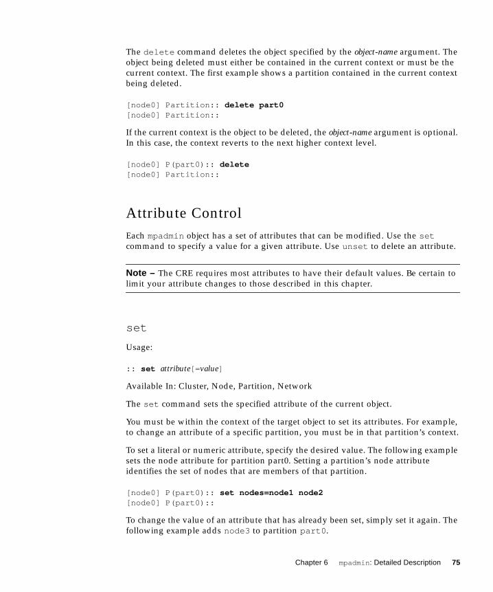
The delete command deletes the object specified by the object-name argument. The
object being deleted must either be contained in the current context or must be the
current context. The first example shows a partition contained in the current context
being deleted.
[node0] Partition:: delete part0[node0] Partition::
If the current context is the object to be deleted, the object-name argument is optional.
In this case, the context reverts to the next higher context level.
[node0] P(part0):: delete[node0] Partition::
Attribute Control
Each mpadmin object has a set of attributes that can be modified. Use the setcommand to specify a value for a given attribute. Use unset to delete an attribute.
Note – The CRE requires most attributes to have their default values. Be certain to
limit your attribute changes to those described in this chapter.
set
Usage:
:: set attribute[= value]
Available In: Cluster, Node, Partition, Network
The set command sets the specified attribute of the current object.
You must be within the context of the target object to set its attributes. For example,
to change an attribute of a specific partition, you must be in that partition’s context.
To set a literal or numeric attribute, specify the desired value. The following example
sets the node attribute for partition part0. Setting a partition’s node attribute
identifies the set of nodes that are members of that partition.
[node0] P(part0):: set nodes=node1 node2[node0] P(part0)::
To change the value of an attribute that has already been set, simply set it again. The
following example adds node3 to partition part0 .
Chapter 6 mpadmin : Detailed Description 75

[node0] P(part0):: set nodes=+node3[node0] P(part0)::
As shown by this example, if the value of an attribute is a list, items can be added to
or removed from the list using the + and - symbols, without repeating items that are
already part of the list.
To set a Boolean attribute, specify the name of the Boolean attribute to be activated.
Do not include =value in the expression. The following example enables partition
part0 .
[node0] P(part0):: set enabled[node0] P(part0)::
Note – If you mistakenly set a Boolean attribute to a value—that is, if you follow a
Boolean attribute’s name with the =value field, mpadmin will ignore the value
assignment and will simply consider the attribute to be active.
unset
Usage:
:: unset attribute
Available In: Cluster, Node, Partition, Network
The unset command deletes the specified attribute from the current object. You
must be within the context of an object to unset any of its attributes.
The following example disables the partition part0 (that is, makes it unavailable for
use).
[node0] P(part0):: unset enabled[node0] P(part0)::
Note – Remember, you cannot use the set command to set Boolean attributes to the
logical 0 ( inactive) state. You must use the unset command.
76 Sun HPC ClusterTools 3.1 Administrator’s Guide • March 2000

Context Navigation
By default, mpadmin commands affect objects that are in the current context—that is,
objects that are in the same context in which the command is invoked. For example,
if the command list is invoked in the Node context, mpadmin will list all the nodes
in the cluster. If list is invoked in the Partition context, it will list all the partitions
in the cluster, as shown below:
[node0] Partition:: listpart0part1part2
[node0] Partition::
mpadmin provides several context navigation commands that enable you to operate
on objects and attributes outside the current context.
current
Usage:
:: current object-name
Available In: Cluster, Node, Partition, Network
The current command changes the current context to the context of the object
specified by object-name. The target object must exist. That is, if it is a partition, you
must already have used the create command to create it. If the target object is a
cluster, node, or network interface, it must have been created by the CRE.
The following example changes the current context from the general Node context to
the context of a specific node, node1 .
[node0] Node:: current node1[node0] N(node1)::
If the name of the target object does not conflict with an mpadmin command, you
can omit the current command. This is illustrated by the following example, where
node1 is the name of the target object.
[node0] Node:: node1[node0] N(hpc-node1)::
This works even when the object is in a different context.
[node0] Partition:: node1[node0] N(node1)::
Chapter 6 mpadmin : Detailed Description 77

Note – The current command must be used when the name of the object is the
same as an mpadmin command. For example, if you have a partition named
Partition , its name conflicts with the command Partition . In this case, to make
the object Partition the current context, you would need to include the currentcommand to make it clear that the Partition term refers to the object and is not an
invocation of the command.
top
Usage:
:: top
Available In: Node, Partition, Network
The top command moves you to the Cluster context. The following example moves
from the Partition context to the Cluster context.
[node0] Partition:: top[node0]::
up
Usage:
:: up
Available In: Node, Partition, Network
The up command moves you up one level from the current context. The following
example moves from the Network context to the context of node node2 .
[node0] N[node2] Network:: up[node0] N[node2]::
node
Usage:
:: node
Available In: Cluster
78 Sun HPC ClusterTools 3.1 Administrator’s Guide • March 2000

The node command moves you from the Cluster context to the Node context.
[node0]:: node[node0] Node::
partition
Usage:
:: partition
Available In: Cluster, Node, Network
The partition command moves you from the Cluster, Node, or Network context
to the Partition context.
[node0]:: partition[node0] Partition::
network
Usage:
:: network
Available In: Node
The network command moves you from a specific Node context to the Network
context associated with that node.
[node0] N[node2]:: network[node0] N[node2] Network::
Information Retrieval
The information retrieval commands display information about
■ The specified object
■ If no object is specified, the current context
dump
Usage:
Chapter 6 mpadmin : Detailed Description 79

:: dump [ object-name]
Available In: Cluster, Node, Partition
The dump command displays the current state of the attributes of the specified object
or of the current context. The object can be
■ The entire cluster.
■ A specific partition.
■ All partitions in the cluster.
■ A specific node.
■ All nodes in the cluster.
The dump command outputs objects in a specific order that corresponds to the
logical order of assignment when a cluster is configured. For example, nodes are
output before partitions because, when a cluster is configured, nodes must exist
before they can be assigned to a partition.
The dump command executes in this hierarchical manner so it can be used to back up
cluster configurations in a format that allows them to be easily restored at a later
time.
The following example shows the dump command being used in this way. In this
example, it is invoked using the –c option on the mpadmin command line, with the
output being directed to a backup file.
# mpadmin –c dump > sunhpc.configuration
Later, when it was time to restore the configuration, mpadmin could read the backup
file as input, using the –f option.
# mpadmin –f sunhpc.configuration
If you wanted to modify the configuration, you could edit the backup file before
before restoring it.
The following example shows the dump command being used to output the attribute
states of the partition part0 .
[node0] Partition:: dump part0 set nodes = node1 node2 node3 set max_total_procs = 4
set name = part0 set enabled
unset no_login[node0] Partition::
80 Sun HPC ClusterTools 3.1 Administrator’s Guide • March 2000

Note – Each attribute is output in the form of a set or unset command so that the
dump output functions as a script.
If you are within the context of the object whose attributes you want to see, you do
not have to specify its name.
[node0] P(part0):: dump set nodes = node1 node2 node3 set max_total_procs = 4
set enabled set name = part0[node0] P(part0)::
list
Usage:
:: list
Available In: Cluster, Node, Partition, Network
The list command lists all of the defined objects in the current context. The
following example shows that there are three partitions defined in the Partition
context.
[node0] Partition:: listpart0part1
part2[node0] Partition::
show
Usage:
:: show [ object-name]
Available In: Cluster, Node, Partition, Network
The show command displays the current state of the attributes of the specified object
object-name, which must be in the current context. The following example displays
the attributes for the partition part0 .
Chapter 6 mpadmin : Detailed Description 81

[node0] Partition:: show part0 set nodes = node0 node1 node2 node3 set max_total_procs = 4
set name = part0 set enabled
unset no_login[node0] Partition::
If, in the above example, you attempted to show node1 , the operation fails because
node1 is not in the current context.
Miscellaneous Commands
This section describes the mpadmin commands connect , echo , help , and quit /
exit .
connect
Usage:
:: connect cluster-name
Available In: Cluster
In order to access any objects or attributes in a Sun HPC cluster, you must be
connected to the cluster.
However, connecting to a cluster ordinarily happens automatically, so you are not
likely to ever need to use the connect command.
The environment variable SUNHPC_CLUSTERnames a default cluster. If no other
action is taken to override this default, any mpadmin session will connect to the
cluster named by this environment variable.
If you issue the mpadmin command on a node that is part of a cluster, you are
automatically connected to that cluster, regardless of the SUNHPC_CLUSTERsetting.
If you are not logged in to the cluster you want to use and you do not want to use
the default cluster, you can use the mpadmin –s option, specifying the name of the
cluster of interest as an argument to the option.
Note – When the CRE creates a cluster, it always names it after the hostname of the
cluster’s master node—that is, the node on which the master daemons are running.
Therefore, whenever you need to specify the name of a cluster, use the hostname of
the cluster’s master node.
82 Sun HPC ClusterTools 3.1 Administrator’s Guide • March 2000

The following example shows the connect command being used to connect to a
cluster whose master node is node0 .
[hpc-demo]:: connect node0[node0]::
echo
Usage:
:: echo text–message
Available In: Cluster, Node, Partition, Network
The echo command prints the specified text on the standard output. If you write a
script to be run with mpadmin –f , you can include the echo command in the script
so that it will print status information as it executes.
[node0]:: echo Enabling part0 and part1Enabling part0 and part1[node0]::
help
Usage:
:: help [ command]
Available In: Cluster, Node, Partition, Network
When invoked without a command argument, the help command lists the mpadmincommands that are available within the current context. The following example
shows help being invoked at the Cluster level.
[node0]:: helpconnect <cluster–name>connect to a Sun HPC clusterset <attribute>[=value]set an attribute in the current contextunset <attribute>delete an attribute in the current contextshow show attributes in current contextdump show all objects on the clusternode go to the node contextpartition go to the partition contextecho ... print the rest of the line on standard outputquit quit mpadmin
Chapter 6 mpadmin : Detailed Description 83

help [command]show information about command command? [command] show information about command command[node0]::
To get a description of a particular command, enter the command name as an
argument to help .
If you specify a context command (node , partition , or network ), mpadmin lists
the commands available within that context. Note that you can specify network as
an argument to help only at the node level.
[node0]:: help nodecurrent <node>set the current node for future commandscreate <node> create a new node with the given namedelete [node] delete a nodelist list all the defined nodesshow [node] show a node’s attributesdump [node] show attributes for a node and its network
interfacesset <attribute>[=value] set the current node’s attributeunset <attribute>delete the current node’s attributenetwork enter the network interface command modeup go up to the Cluster level command prompttop go up to the Cluster level command promptecho ... print the rest of the line on standard outputhelp [command]show information about command command? [command] show information about command command[node0]::
The "?" character is a synonym for help .
quit /exit
Usage:
:: quit
:: exit
Available In: Cluster, Node, Partition, Network
Entering either quit or exit causes mpadmin to terminate and return you to the
shell level.
Example:
[node0]:: quit#
84 Sun HPC ClusterTools 3.1 Administrator’s Guide • March 2000

Example:
[node0] N(node2):: exit#
Additional mpadmin FunctionalityThis section describes other functionality provided by mpadmin .
Multiple Commands on a Line
Because mpadmin interprets its input, if you issue more than one command on a
line, mpadmin will execute them sequentially in the order they appear.
The following example shows how to display a list of nodes when not in the Node
context. The node command switches to the Node context and the list command
generates a list for that context.
[node0]:: node list node0 node1 node2 node3[node0] Node::
The following example sets the enabled attribute on partition part1 . The part1entry acts as a command that switches the context from part0 to part1 and the
set command turns on the enabled attribute.
[node0] P[part0]:: part0 set enabled[node0] P(part0)::
Command Abbreviation
You can abbreviate commands to the shortest string of at least two letters so long as
it is still unique within the current context.
Chapter 6 mpadmin : Detailed Description 85

[node0] Node:: pa[node0] Partition:: li
part0 part1
part2part3
[node0] Partition:: part2[node0] P(part2):: sh set enabled set max_total_procs = 4 set name = part2 set nodes = node0 node1[node0] P(part2)::
Note – The names of objects cannot be abbreviated.
Using mpadminThis section explains how to use mpadmin to perform the principal administrative
tasks involved in setting up and maintaining a Sun HPC cluster. It describes the
following tasks:
■ Logging in to the cluster
■ Customizing cluster-level attributes
■ Managing nodes and network interfaces
■ Managing partitions
Note on Naming Partitions and Custom
Attributes
You can assign names to partitions and to custom attributes. Custom attributes are
attributes that are not part of the default CRE database; they are discussed in
“Setting Custom Attributes” on page 102.
Names must start with a letter and are case sensitive. The following characters can
be used:
86 Sun HPC ClusterTools 3.1 Administrator’s Guide • March 2000

ABCDEFGHIJKLMNOPQRSTUVWXYZ
abcdefghijklmnopqrstuvwxyz
0123456789–_.
The only limit to name length is the limit imposed by Solaris on host names—it is
ordinarily set at 256 characters.
Note – Do not begin an attribute name with the characters mp_. This starting
sequence is reserved by the CRE.
Nodes and partitions have separate name spaces. Thus, you can have a partition
named Parallel that contains a node named Parallel .
Logging In to the Cluster
It is assumed that you are logged in to a node that is part of the cluster you want to
set up. If the node you are logged in to is not part of any cluster, set the
SUNHPC_CLUSTERenvironment variable to the name of the target cluster. For
example,
# setenv SUNHPC_CLUSTER node0
makes node0 the default cluster. Remember, a cluster’s name is the same as the host
name of its master node.
Once you are connected to the cluster, you can start using mpadmin to perform the
administrative tasks described below.
Chapter 6 mpadmin : Detailed Description 87

When you start up an mpadmin interactive session, you begin at the Cluster level.
TABLE 6-3 lists the mpadmin commands that can be used in the Cluster context.
Customizing Cluster-Level Attributes
This section describes various Cluster-level attributes that you may want to modify.
TABLE 6-4 lists the attributes that can be changed in the Cluster context.
TABLE 6-3 Cluster-Level mpadmin Commands
Command Synopsis
connect cluster-name Connect to a Sun HPC cluster named cluster-name. You
will not need to use this command.
show Show cluster attributes.
dump Show all objects in the Sun HPC cluster.
set attribute[=value] Set a cluster-level attribute.
unset attribute Delete a cluster-level attribute.
node Enter the Node context.
partition Enter the Partition context.
echo ... Print the rest of the line on the standard output.
quit / exit Quit mpadmin .
help [command] / ? Show information about commands.
TABLE 6-4 Cluster-Level Attributes
Attribute Kind Description
default_interactive_partition Value Specifies the default partition.
logfile Value Specifies an optional output file
for logging CRE daemon error
messages.
administrator Value Specifies an email address for the
system administrator(s).
88 Sun HPC ClusterTools 3.1 Administrator’s Guide • March 2000

default_interactive_partition
This attribute specifies the default partition for running MPI jobs. Its value is used
by the command mprun , which is described in the Sun HPC ClusterTools 3.1 User’sGuide.
For example, to make a partition named part0 the default partition, enter the
following in the Cluster context:
[node0]:: set default_interactive_partition=part0
When a user executes a program via mprun , the CRE decides where to run the
program, based on the following criteria:
1. Check for the command-line –p option. If a partition is specified, execute the
program in that partition. If the specified partition is invalid, the command will
fail.
2. Check to see if the MPRUN_FLAGSenvironment variable specifies a default
partition. If so, execute the program in that partition. If the specified partition is
invalid, the command will fail.
3. Check to see if the SUNHPC_PARTenvironment variable has a value set. If it
specifies a default partition, execute the program in that partition. If the specified
partition is invalid, then check to see if the user is logged in to any partition. If so,
execute the program in that partition.
4. Check to see if the user is logged in to a partition. Execute the program in that
partition.
5. If none of these checks yields a partition name, check for the existence of the
default_interactive_partition attribute. If it specifies a partition, execute
the program in that partition.
logfile
The logfile attribute allows you to log CRE messages in a file separate from all
other system messages. For example, if you enter:
[node0]:: set logfile=/home/wmitty/cre-messages
the CRE will output its messages to the file /home/wmitty/cre-messages . If
logfile is not set, CRE messages will be passed to syslog , which will store them
with other system messages in /var/adm/messages .
Note – A full path name must be specified when setting the logfile attribute.
Chapter 6 mpadmin : Detailed Description 89

administrator
Set the administrator attribute to identify the system administrator. For example,
to specify the email address of the system administrator:
[node0]:: set administrator="[email protected]"
Note the use of double quotation marks.
Managing Nodes and Network Interfaces
Ordinarily, the only administrative action that you need to take with nodes is to
enable them for use. Or, if you want to temporarily make a node unavailable for use,
disable it.
Other node-related administrative tasks—such as naming the nodes, identifying the
master node, setting memory and process limits, and setting the node’s partition
attribute—are either handled by the CRE automatically or are controlled via
partition-level attributes.
There are no administrative actions required by network interface attributes. They
are all controlled by the CRE. The only actions you might want to take with respect
to network interfaces is to list them or display their attribute values.
Node Commands
The table below lists the mpadmin commands that can be used at the Node level.
TABLE 6-5 Node-Level mpadmin Commands
Command Synopsis
current node Set the context to the specified node for future commands.
create node Create a new node with the given name.
delete [node] Delete a node.
list List all the defined nodes.
show [node] Show a node’s attributes.
dump [node] Show the attributes of the node and its network interfaces.
set attribute[=value] Set the specified attribute of the current node.
unset attribute Delete the specified attribute of the current node.
network Move to the network interface command level.
up Move to the next higher level (Top) command context.
top Move to the Top level command context.
echo ... Print the rest of the line on the standard output.
help [command] Show information about commands (?).
90 Sun HPC ClusterTools 3.1 Administrator’s Guide • March 2000

Node Attributes
Nodes are defined by many attributes, most of which are not accessible to mpadmincommands. Although you are not able to affect these attributes, it can be helpful to
know of their existence and meaning; hence, they are listed and briefly described in
TABLE 6-6.
TABLE 6-7 lists the Node-level attributes that can be set via mpadmin commands.
However, the enabled and max_total_procs are the only node attributes that
you can safely modify.
TABLE 6-6 Node Attributes That Cannot Be Set by the System Administrator
Attribute Kind Description
cpu_idle Value Percent of time CPU is idle.
cpu_iowait Value Percent of time CPU spent in I/O wait state.
cpu_kernel Value Percent of time CPU spent in kernel state.
cpu_type Value Type of CPU, for example, sparc .
cpu_user Value Percent of time CPU spends running user’s
program.
load1 Value Load average for the past minute.
load5 Value Load average for the past five minutes.
load15 Value Load average for the past 15 minutes.
manufacturer Value Manufacturer of the node, e.g.,
Sun_Microsystems .
mem_free Value Node’s available RAM (in Mbytes).
mem_total Value Node’s total physical memory (in Mbytes).
ncpus Value Number of CPUs in the node.
offline Boolean Set automatically by the system if the tm.spmddaemon on the node stops running or is
unresponsive; if set, prevents jobs from being
spawned on the node.
os_arch_kernel Value Node’s kernel architecture (same as output from
arch –k , for example, sun4u ).
os_name Value Name of the operating system running on the node,
for example, SunOS.
os_release Value Operating system’s release number, for example,
5.5.1
os_release_maj Value Operating system’s major release number, for
example, 5.
Chapter 6 mpadmin : Detailed Description 91

enabled
The attribute enabled is set by default when the CRE daemons start on a node.
Unsetting it prevents new jobs from being spawned on the node.
A partition can list a node that is not enabled as a member. However, jobs will
execute on that partition as if that node were not a member.
os_release_min Value Operating system’s minor release number, for
example, 5 or 6.
os_version Value Operating system’s version, for example, GENERIC.
serial_number Value Hardware serial number or host id.
swap_free Value Node’s available swap space (in Mbytes).
swap_total Value Node’s total swap space (in Mbytes).
update_time Value When this information was last updated.
update_time Value When this information was last updated.
TABLE 6-7 Node Attributes That Can Be Set by the System Administrator
Attribute Kind Description
enabled Boolean Set if the node is enabled, that is, if it is ready to
accept jobs.
master Boolean Specify node on which the master daemons are
running as an argument to mprun .
max_locked_mem Value Maximum amount of shared memory allowed to be
locked down by Sun MPI processes (in Kbytes).
max_total_procs Value Maximum number of Sun HPC processes per node.
min_unlocked_mem
Value Minimum amount of shared memory not to be
locked down by Sun MPI processes (in Kbytes).
name Value Name of the node; this is predefined and must not
be set via mpadmin .
partition Value Partition of which node is a member.
shmem_minfree Value Fraction of swap space kept free for non-MPI use.
TABLE 6-6 Node Attributes That Cannot Be Set by the System Administrator (Continued)
Attribute Kind Description
92 Sun HPC ClusterTools 3.1 Administrator’s Guide • March 2000

master
Note – You must not change this node attribute. The CRE automatically sets it to the
hostname of the node on which the master CRE daemons are running. This happens
whenever the CRE daemons start.
max_locked_mem and min_unlocked_mem
Note – You should not change these node attributes. They are described here so that
you will be able to interpret their values when node attributes are displayed via the
dump or show commands.
The max_locked_mem and min_unlocked_mem attributes limit the amount of
shared memory available to be locked down for use by Sun MPI processes. Locking
down shared memory guarantees maximum speed for Sun MPI processes by
eliminating delays caused by swapping memory to disk. However, locking physical
memory can have undesirable side effects because it prevents that memory from
being used by other processes on the node.
The Solaris software provides two related tunable kernel parameters:
■ tune_t_minasmem , which is similar to min_unlocked_mem
■ pages_pp_maximum , which is similar to max_locked_mem
The CRE parameters impose limits only on MPI programs, while the kernel
parameters limit all processes. Also, the kernel parameter units are pages rather than
Kbytes. Refer to your Solaris documentation for more information about
tune_t_minasmem and pages_pp_maximum .
max_total_procs
You limit the number of mprun processes allowed to run concurrently on a node by
setting this attribute to an integer.
[node0] P(part0):: set max_total_procs=10[node0] P(part0)::
If max_total_procs is set at the node level, that value overrides any value set at
the partition level.
By default, max_total_procs is unset . The CRE does not impose any limit on the
number of processes allowed on a node.
Chapter 6 mpadmin : Detailed Description 93

name
A node’s name is predefined at installation time in the hpc_config file. You must
not change it by setting this attribute.
partition
Note – There is no need to set this attribute. The CRE sets it automatically if the
node is included in any partition configuration(s). See “Nodes have to exist in the
CRE database before you can add them to partitions.” on page 97 for additional
details.
A node can belong to multiple partitions, but only one of those partitions can be
enabled at a time. No matter how many partitions a node belongs to, the
partition attribute shows only one partition name—that name is always the name
of the enabled partition, if one exists for that node.
shmem_minfree
Note – You should not change this node attribute. It is described here so that you
will be able to interpret its value when node attributes are displayed via the dump or
show commands.
The shmem_minfree attribute reserves some portion of the /tmp file system for
non-MPI use.
For example, if /tmp is 1 Gbyte and shmem_minfree is set to 0.2, any time free
space on /tmp drops below 200 Mbytes (1 Gbyte * 0.2), programs using the MPI
shared memory protocol will not be allowed to run.
[node0] N(node1):: set shmem_minfree=0.2
shmem_minfree must be set to a value between 0.0 and 1.0. When shmem_minfreeis unset, it defaults to 0.1.
This attribute can be set on both nodes and partitions. If both are set to different
values, the node attribute overrides the partition attribute.
94 Sun HPC ClusterTools 3.1 Administrator’s Guide • March 2000

Deleting Nodes
If you permanently remove a node from the Sun HPC cluster, you should then delete
the corresponding node object from the CRE resource database.
Recommendations
Before deleting a node:
■ Remove it from any enabled partition by unsetting its partition attribute
(automatically removing the node from the partition’s nodes attribute list), or by
removing it from the partition’s nodes attribute list. See “Partition Attributes” on
page 98 for details.
■ Wait for any jobs running on it to terminate, or stop them using the mpkillcommand, which is described in the Sun HPC Cluster Runtime Environment 1.0User’s Guide.
Using the delete Command
To delete a node, use the delete command within the context of the node you want
to delete.
[node0] N(node3):: delete[node0] Node::
Managing Partitions
Partitions are logical collections of nodes that work cooperatively to run programs
on the Sun HPC cluster. An MPI job can run on a single partition or on the
combination of a single partition and one or more nodes that are not members of any
partition. MPI jobs cannot run in multiple partitions.
You must create a partition and enable it before you can run MPI programs on your
Sun HPC cluster. Once a partition is created, you can configure it to meet the specific
needs of your site and enable it for use.
Once a partition is created and enabled, you can run serial or parallel jobs on it.
Serial programs run on a single node of a partition. Parallel programs run on any
number of nodes of a partition in parallel.
The CRE performs load balancing on shared partitions. When you use mprun to
execute a program on a shared partition, the CRE automatically runs it on the least-
loaded nodes that satisfy any specified resource requirements.
Chapter 6 mpadmin : Detailed Description 95
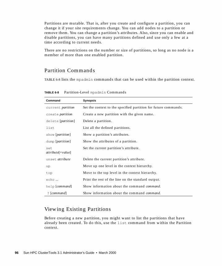
Partitions are mutable. That is, after you create and configure a partition, you can
change it if your site requirements change. You can add nodes to a partition or
remove them. You can change a partition’s attributes. Also, since you can enable and
disable partitions, you can have many partitions defined and use only a few at a
time according to current needs.
There are no restrictions on the number or size of partitions, so long as no node is a
member of more than one enabled partition.
Partition Commands
TABLE 6-8 lists the mpadmin commands that can be used within the partition context.
Viewing Existing Partitions
Before creating a new partition, you might want to list the partitions that have
already been created. To do this, use the list command from within the Partition
context.
TABLE 6-8 Partition-Level mpadmin Commands
Command Synopsis
current partition Set the context to the specified partition for future commands.
create partition Create a new partition with the given name.
delete [partition] Delete a partition.
list List all the defined partitions.
show [partition] Show a partition’s attributes.
dump [partition] Show the attributes of a partition.
setattribute[=value]
Set the current partition’s attribute.
unset attribute Delete the current partition’s attribute.
up Move up one level in the context hierarchy.
top Move to the top level in the context hierarchy.
echo ... Print the rest of the line on the standard output.
help [command] Show information about the command command.
? [command] Show information about the command command.
96 Sun HPC ClusterTools 3.1 Administrator’s Guide • March 2000

[node0] Partition:: list part0
part1[node0] Partition::
Creating a Partition
To create a partition, use the create command, followed by the name of the new
partition. “Note on Naming Partitions and Custom Attributes” on page 86 discusses
the rules for naming partitions.
For example:
[node0] Partition:: create part0[node0] P(part0)::
The create command automatically changes the context to that of the new
partition.
At this point, your partition exists by name but contains no nodes. You must assign
nodes to the partition before using it. You can do this by setting the partition’s
nodes attribute. Note these prerequisites:
■ Nodes have to exist in the CRE database before you can add them to partitions.
■ A node must be enabled for it to be an active member of a partition. If a node is
configured as a partition member, but is not enabled, it will not participate in jobs
that run on that partition.
Configuring Partitions
You can configure partitions by setting and deleting their attributes using the setand unset commands. shows commonly used partition attributes.
You can combine the attributes listed in TABLE 6-10 in any way that makes sense for
your site.
TABLE 6-9 Common Partitions and Their Attributes
Partition Type Relevant Attributes Recommended Value
Login no_logins not set
Shared max_total_procs not set or set greater than 1
Dedicated max_total_procsno_logins
=1
set
Serial no_mp_jobs set
Parallel no_mp_jobs not set
Chapter 6 mpadmin : Detailed Description 97

Partitions, once created, can be enabled and disabled. This lets you define many
partitions but use just a few at a time. For instance, you might want to define a
number of shared partitions for development use and dedicated partitions for
executing production jobs, but have only a subset available for use at a given time.
Partition Attributes
TABLE 6-10 lists the predefined partition attributes. To see their current values, use the
mpadmin show command.
enabled
Set the enabled attribute to make a partition available for use.
By default, the enabled attribute is not set when a partition is created.
max_locked_mem and min_unlocked_mem
You should not change these partition attributes.
max_total_procs
To limit the number of simultaneously running mprun processes allowed on all
nodes in a partition or in all partitions, set the max_total_procs attribute in a
specific Node context or in the general Partition context.
TABLE 6-10 Predefined Partition Attributes
Attribute Kind Description
enabled Boolean Set if the partition is enabled, that is, if it is ready
to accept logins or jobs.
max_locked_mem Value Maximum amount of shared memory allowed to
be locked down by MPI processes (in Kbytes).
max_total_procs Value Maximum number of simultaneously running
processes allowed on each node in the partition.
min_unlocked_mem Value Minimum amount of shared memory that may not
be locked down by MPI processes (in Kbytes).
name Value Name of the partition.
no_logins Boolean Disallow logins.
no_mp_tasks Boolean Disallow multiprocess parallel jobs.
nodes Value List of nodes in the partition.
shmem_minfree Value Fraction of swap space kept free for non-MPI use.
98 Sun HPC ClusterTools 3.1 Administrator’s Guide • March 2000

[node0] P(part0):: set max_total_procs=10[node0] P(part0)::
You can set max_total_procs if you want to limit the load on a partition. By
default, max_total_procs is unset .
If max_total_procs is set at the node level, that value overrides any value set at
the partition level.
The CRE does not impose any limit on the number of processes allowed on a node.
name
The name attribute is set when a partition is created. To change the name of a
partition, set its name attribute to a new name.
[node0] P(part0):: set name=part1[node0] P(part1)::
See “Note on Naming Partitions and Custom Attributes” on page 86 for partition
naming rules.
no_logins
To prohibit users from logging in to a partition, set the no_logins attribute.
[node0] P(part1):: set no_logins[node0] P(part1)::
no_mp_jobs
To prohibit multiprocess parallel jobs from running on a partition—that is, to make a
serial partition—set the no_mp_jobs attribute.
[node0] P(part1):: set no_mp_jobs[node0] P(part1)::
nodes
To specify the nodes that are members of a partition, set the partition’s nodesattribute.
Chapter 6 mpadmin : Detailed Description 99

[node0] P(part1):: set nodes=node1[node0] P(part1):: show set nodes = node1 set enabled[node0] P(part1)::
The value you give the nodes attribute defines the entire list of nodes in the
partition. To add a node to an already existing node list without retyping the names
of nodes that are already present, use the + (plus) character.
[node0] P(part1):: set nodes=+node2 node3[node0] P(part1):: show set nodes = node0 node1 node2 node3 set enabled[node0] P(part1)::
Similarly, you can use the – (minus) character to remove a node from a partition.
To assign a range of nodes to the nodes attribute, use the : (colon) syntax. This
example assigns to part0 all nodes whose names are alphabetically greater than or
equal to node0 and less than or equal to node3 :
[node0] P(part1):: set nodes = node0:node3[node0] P(part1)::
Setting the nodes attribute of an enabled partition has the side effect of setting the
partition attribute of the corresponding nodes. Continuing the example, setting
the nodes attribute of part1 affects the partition attribute of node2 :
[node0] P(part1):: node node2[node0] N(node2):: show set partition = part1[node0] N(node2)::
A node cannot be a member of more than one enabled partition. If you try to add a
node that is already in an enabled partition, mpadmin returns an error message.
[node0] P(part1):: show set nodes = node0 node1 node2 node3 set enabled[node0] P(part1):: current part0[node0] P(part0):: set enabled[node0] P(part0):: set nodes=node1mpadmin: node1 must be removed from part1 before it can be added topart0
Unsetting the nodes attribute of an enabled partition has the side effect of unsetting
the partition attribute of the corresponding node.
100 Sun HPC ClusterTools 3.1 Administrator’s Guide • March 2000

Unsetting the nodes attribute of a disabled partition removes the nodes from the
partition but does not change their partition attributes.
shmem_minfree
Use the shmem_minfree attribute to reserve some portion of the /tmp file system
for non-MPI use.
For example, if /tmp is 1 Gbyte and shmem_minfree is set to 0.2, any time free
space on /tmp drops below 200 Mbytes (1 Gbyte * 0.2), programs using the MPI
shared memory protocol will not be allowed to run.
[node0] P(part1):: set shmem_minfree=0.2
shmem_minfree must be set to a value between 0.0 and 1.0. When shmem_minfreeis unset, it defaults to 0.1.
This attribute can be set on both nodes and partitions. If both are set, the node’s
shmem_minfree attribute overrides the partition’s shmem_minfree attribute.
Enabling Partitions
A partition must be enabled before users can run programs on it. Before enabling a
partition, you must disable any partitions that share nodes with the partition that
you are about to enable.
To enable a partition, set its enabled attribute.
[node0] P(part0):: set enabled[node0] P(part0)::
Now the partition is ready for use.
Enabling a partition has the side effect of setting the partition attribute of every
node in that partition.
If you try to enable a partition that shares a node with another enabled partition,
mpadmin prints an error message.
[node0] P(part1):: show set nodes = node1 node2 node3 set enabled[node0] P(part1):: current part2[node0] P(part2):: show set nodes = node1[node0] P(part2):: set enabledmpadmin: part1/node1: partition resource conflict
Chapter 6 mpadmin : Detailed Description 101

Disabling Partitions
To disable a partition, unset its enabled attribute.
[node0] P(part0):: unset enabled[node0] P(part0)::
Now the partition can no longer be used.
Any jobs that are running on a partition when it is disabled will continue to run.
After disabling a partition, you should either wait for any running jobs to terminate
or stop them using the mpkill command. This is described in the Sun HPC ClusterRuntime Environment 1.0 User’s Guide.
Deleting Partitions
Delete a partition when you do not plan to use it anymore.
Note – Although it is possible to delete a partition without first disabling it, you
should disable the partition by unsetting its enabled attribute before deleting it.
To delete a partition, use the delete command in the context of the partition you
want to delete.
[node0] P(part0):: delete[node0] Partition::
Setting Custom Attributes
Sun HPC ClusterTools software does not limit you to the attributes listed. You can
define new attributes as desired.
For example, if a node has a special resource that will not be flagged by an existing
attribute, you may want to set an attribute that identifies that special characteristic.
In the following example, node node3 has a frame buffer attached. This feature is
captured by setting the custom attribute has_frame_buffer for that node.
[node0] N(node3):: set has_frame_buffer[node0] N(node3)::
Users can then use the attribute has_frame_buffer to request a node that has a
frame buffer when they execute programs. For example, use the following mpruncommand lines to select a node with or without a frame buffer, respectively:
102 Sun HPC ClusterTools 3.1 Administrator’s Guide • March 2000

% mprun -R "has_frame_buffer"
% mprun -R "\!has_frame_buffer"
See “Note on Naming Partitions and Custom Attributes” on page 86 for restrictions
on attribute names.
Chapter 6 mpadmin : Detailed Description 103

104 Sun HPC ClusterTools 3.1 Administrator’s Guide • March 2000

CHAPTER 7
hpc.conf Configuration File
This chapter discusses the Sun HPC ClusterTools configuration file hpc.conf ,
which defines various attributes of a Sun HPC cluster. A single hpc.conf file is
shared by all the nodes in a cluster. It resides in /opt/SUNWhpc/conf .
Note – This configuration file is also used on LSF-based clusters, but it resides in a
different location. See Appendix C.
hpc.conf is organized into six sections, which are summarized below and
illustrated in TABLE 7-1.
■ The ShmemResource section defines certain shared memory attributes.
■ The Netif section lists and ranks all network interfaces to which Sun HPC nodes
are connected.
■ The MPIOptions section allows the administrator to control certain MPI
parameters by setting them in the hpc.conf file.
■ The PFSFileSystem section names and defines all parallel file systems in the
Sun HPC cluster.
■ The PFSServers section names and defines all parallel file system servers in the
Sun HPC cluster.
■ The HPCNodessection is not used by the CRE. It applies only in an LSF-based
runtime environment (as described in Appendix C).
Each configuration section is bracketed by a Begin/End keyword pair and, when a
parameter definition involves multiple fields, the fields are separated by spaces.
Sun HPC ClusterTools 3.1 software is distributed with an hpc.conf template, which
is installed by default in /opt/SUNWhpc/examples/cre/hpc.conf.template .
You should copy this file to /opt/SUNWhpc/conf/hpc.conf and edit it to suit
your site’s specific configuration requirements.
105

Note – When any changes are made to hpc.conf , the system should be in a
quiescent state. To ensure that it is safe to edit hpc.conf , shut down the nodal and
master CRE daemons as described in “To shut down the CRE daemons without
shutting down the Solaris operating environment, execute the following commands
as root:” on page 13. If you change PFSFileSystem or PFSServers sections, you
must also unmount any PFS file systems first. See Chapter 4 for details.
ShmemResource SectionThe ShmemResource section provides the administrator with two parameters that
control allocation of shared memory and swap space: MaxAllocMem and
MaxAllocSwap . This special memory allocation control is needed because some Sun
HPC ClusterTools components use shared memory.
TABLE 7-1 General Organization of the hpc.conf File
Begin ShmemResource :End ShmemResource
Begin NetifNAME RANK MTU STRIPE PROTOCOL LATENCY BANDWIDTH : : : : : : :End Netif
Begin MPIOptions=queue_name :End MPIOptions
Begin PFSFileSystem=fs_nameNODE DEVICE THREADS : : :End PFSFileSystem
Begin PFSServersNODE BUFFER_SIZE : :End PFSServers
Begin HPCNodes : :End HPCNodes
106 Sun HPC ClusterTools 3.1 Administrator’s Guide • March 2000

TABLE 7-2 shows the ShmemResource template that is in the hpc.conf file that is
shipped with Sun HPC ClusterTools 3.1 software.
To set MaxAllocMem and/or MaxAllocSwap limits, remove the comment character
(#) from the start of each line and replace the current value, 0x7fffffffffffffff ,
with the desired limit.
Guidelines for Setting Limits
The Sun HPC ClusterTools internal shared memory allocator permits an application
to use swap space, the amount of which is the smaller of:
■ The value (in bytes) given by the MaxAllocSwap parameter
■ 90% of available swap on a node
If MaxAllocSwap is not specified, or if zero or a negative value is specified, 90% of
a node’s available swap will be used as the swap limit.
The MaxAllocMem parameter can be used to limit the amount of shared memory
that can be allocated. If a smaller shared memory limit is not specified, the shared
memory limit will be 90% of available physical memory.
The following Sun HPC ClusterTools components use shared memory:
■ The CRE uses shared memory to hold cluster and job table information. Its
memory use is based on cluster and job sizes and is not controllable by the user.
Shared memory space is allocated for the CRE when it starts up and is not
affected by MaxAllocMem and MaxAllocSwap settings. This ensures that the
CRE can start up no matter how low these memory-limit variables have been set.
■ MPI uses shared memory for communication between processes that are on the
same node. The amount of shared memory allocated by a job can be controlled by
MPI environment variables.
■ Sun S3L uses shared memory for storing data. An MPI application can allocate
parallel arrays whose subgrids are in shared memory. This is done with the utility
S3L_declare_detailed() .
TABLE 7-2 ShmemResource Section Example
#Begin ShmemResource#MaxAllocMem 0x7fffffffffffffff#MaxAllocSwap 0x7fffffffffffffff#End ShmemResource
Chapter 7 hpc.conf Configuration File 107

Note – Sun S3L supports a special form of shared memory known as Intimate SharedMemory (ISM), which reserves a region in physical memory for shared memory use.
What makes ISM space special is that it is not swappable and, therefore, cannot be
made available for other use. For this reason, the amount of memory allocated to
ISM should be kept to a minimum.
Note – Shared memory and swap space limits are applied per-job on each node.
If you have set up your system for dedicated use (only one job at a time is allowed),
you should leave MaxAllocMem and MaxAllocSwap undefined. This will allow jobs
to maximize use of swap space and physical memory.
If, however, multiple jobs will share a system, you may want to set MaxAllocMem to
some level below 50% of total physical memory. This will reduce the risk of having a
single application lock up physical memory. How much below 50% you choose to set
it will depend on how many jobs you expect to be competing for physical memory at
any given time.
Note – When users make direct calls to mmap(2) or shmget (2), they are not limited
by the MaxAllocMem and MaxAllocSwap variables. These utilities manipulate
shared memory independently of the MaxAllocMem and MaxAllocSwap values.
108 Sun HPC ClusterTools 3.1 Administrator’s Guide • March 2000

H
Netif SectionThe Netif section identifies the network interfaces supported by the Sun HPC
cluster and specifies the rank, and striping attributes for each interface. The
hpc.conf template that is supplied with Sun HPC ClusterTools 3.1 software
contains a default list of supported network interfaces as well as their default
ranking. TABLE 7-3 represents a portion of the default Netif section.
Interface Names
The NAMEcolumn lists the names of possible network interface types.
TABLE 7-3 Netif Section Example
Begin NetifNAME RANK MTU STRIPE PROTOCOL LATENCY BANDWIDTmidn 0 16384 0 tcp 20 150idn 10 16384 0 tcp 20 150sci 20 32768 1 tcp 20 150mscid 30 32768 1 tcp 20 150scid 40 32768 1 tcp 20 150scirsm 45 32768 1 rsm 20 150mba 50 8192 0 tcp 20 150ba 60 8192 0 tcp 20 150mfa 70 8192 0 tcp 20 150fa 80 8192 0 tcp 20 150macip 90 8192 0 tcp 20 150acip 100 8192 0 tcp 20 150manfc 110 16384 0 tcp 20 150anfc 120 16384 0 tcp 20 150mbf 130 4094 0 tcp 20 150bf 140 4094 0 tcp 20 150mbe 150 4094 0 tcp 20 150be 160 4094 0 tcp 20 150mqfe 163 4094 0 tcp 20 150qfe 167 4094 0 tcp 20 150mhme 170 4094 0 tcp 20 150hme 180 4094 0 tcp 20 150mle 190 4094 0 tcp 20 150le 200 4094 0 tcp 20 150msmc 210 4094 0 tcp 20 150smc 220 4094 0 tcp 20 150End Netif
Chapter 7 hpc.conf Configuration File 109

Rank Attribute
The rank of an interface is the order in which that interface is preferred over other
interfaces. That is, if an interface with a rank of 0 is available when a communication
operation begins, it will be selected for the operation before interfaces with ranks of
1 or greater. Likewise, an available rank 1 interface will be used before interfaces
with a rank of 2 or greater.
Note – Because hpc.conf is a shared, cluster-wide configuration file, the rank
specified for a given interface will apply to all nodes in the cluster.
Network ranking decisions are usually influenced by site-specific conditions and
requirements. Although interfaces connected to the fastest network in a cluster are
often given preferential ranking, raw network bandwidth is only one consideration.
For example, an administrator might decide to dedicate one network that offers very
low latency, but not the fastest bandwidth to all cluster intra-cluster communication
and use a higher-capacity network for connecting the cluster to other systems.
MTU Attribute
The MTUcolumn is a placeholder. Its contents are not used at this time.
Stripe Attribute
Sun HPC ClusterTools 3.1 software supports scalable communication between
cluster nodes through striping of MPI messages over SCI interfaces. In striped
communication, a message is split into smaller packets and transmitted in two or
more parallel streams over a set of network interfaces that have been logically
combined into a stripe-group.
The STRIPE column allows the administrator to include individual SCI network
interfaces in a stripe-group pool. Members of this pool are available to be included in
logical stripe groups. These stripe groups are formed on an as-needed basis,
selecting interfaces from this stripe-group pool.
To include the SCI interface in a stripe-group pool, set its STRIPE value to 1. To
exclude an interface from the pool, specify 0. Up to four SCI network interface cards
per node can be configured for stripe-group membership.
When a message is submitted for transmission over the SCI network, an MPI
protocol module distributes the message over as many SCI network interfaces as are
available.
110 Sun HPC ClusterTools 3.1 Administrator’s Guide • March 2000

Stripe-group membership is optional so you can reserve some SCI network
bandwidth for non-striped use. To do so, simply set STRIPE = 0 on the SCI network
interface(s) you wish to reserve in this way.
Protocol Attribute
The Protocol column identifies the communication protocol used by the interface.
The scirsm interface employs the RSM (Remote Shared Memory) protocol. The
others all use TCP (Transmission Control Protocol).
Latency Attribute
The Latency column is a placeholder. Its contents are not used at this time.
Bandwidth Attribute
The Bandwidth column is a placeholder. Its contents are not used at this time.
MPIOptions SectionThe MPIOptions section provides a set of options that control MPI communication
behavior in ways that are likely to affect message-passing performance. It contains
two templates with predefined option settings. These templates are shown in
TABLE 7-4.
■ General-purpose, multiuser template – The first template in the MPIOptions
section is designed for general-purpose use at times when multiple message-
passing jobs will be running concurrently.
■ Performance template – The second template is designed to maximize the
performance of message-passing jobs when only one job is allowed to run at a
time.
Note – The first line of each template contains the phrase "Queue=xxxx." This is
because the queue-based LSF workload management runtime environment uses the
same hpc.conf file as the CRE.
Chapter 7 hpc.conf Configuration File 111

The options in the general-purpose template are the same as the default settings for
the Sun MPI library. In other words, you do not have to uncomment the general-
purpose template to have its option values be in effect. This template is provided in
the MPIOptions section so that you can see what options are most beneficial when
operating in a multiuser mode.
If you want to use the performance template, do the following:
■ Delete the "Queue=performance " phrase from the Begin MPIOptions line.
■ Delete the comment character (#) from the beginning of each line of the
performance template, including the Begin MPIOptions and End MPIOptionslines.
The resulting template should appear as follows:
Begin MPIOptionscoscheduling offspin onEnd MPIOptions
112 Sun HPC ClusterTools 3.1 Administrator’s Guide • March 2000

TABLE 7-5 provides brief descriptions of the MPI runtime options that can be set in
hpc.conf . Each description identifies the default value and describes the effect of
each legal value.
Some MPI options not only control a parameter directly, they can also be set to a
value that passes control of the parameter to an environment variable. Where an
MPI option has an associated environment variable, TABLE 7-5 names the
environment variable
TABLE 7-4 MPIOptions Section Example
# The following is an example of the options that affect the runtime# environment of the MPI library. The listings below are identical# to the default settings of the library. The "queue=hpc" phrase# makes this an LSF-specific entry, and only for the queue named hpc.# These options are a good choice for a multiuser queue. To be# recognized by CRE, the "Queue=hpc" needs to be removed.## Begin MPIOptions queue=hpc# coscheduling avail# pbind avail# spindtimeout 1000# progressadjust on# spin off## shm_numpostbox 16# shm_shortmsgsize 256# rsm_numpostbox 15# rsm_shortmsgsize 401# rsm_maxstripe 2# End MPIOptions
# The listing below is a good choice when trying to get maximum# performance out of MPI jobs that are running in a queue that# allows only one job to run at a time.## Begin MPIOptions Queue=performance# coscheduling off# spin on# End MPIOptions
Chapter 7 hpc.conf Configuration File 113

TABLE 7-5 MPI Runtime Options
Values
Option Default Other Description
coscheduling avail Allows spind use to be controlled by
the environment variable
MPI_COSCHED. If MPI_COSCHED=0 or is
not set, spind is not used. If
MPI_COSCHED=1, spind must be used.
on Enables coscheduling; spind is used.
This value overrides MPI_COSCHED=0.
off Disables coscheduling; spind is not to
be used. This value overrides
MPI_COSCHED=1.
pbind avail Allows processor binding state to be
controlled by the environment variable
MPI_PROCBIND. If MPI_PROCBIND=0or is not set, no processes will be bound
to a processor. This is the default.
If MPI_PROCBIND=1, all processes on a
node will be bound to a processor.
on All processes will be bound to
processors. This value overrides
MPI_PROCBIND=0.
off No processes on a node are bound to a
processor. This value overrides
MPI_PROCBIND=1.
spindtimeout 1000 When polling for messages, a process
waits 1000 milliseconds for spind to
return. This equals the value to which
the environment variable
MPI_SPINDTIMEOUTis set.
integer To change the default timeout, enter an
integer value specifying the number of
milliseconds the timeout should be.
progressadjust on Allows user to set the environment
variable MPI_SPIN .
off Disables user’s ability to set the
environment variable MPI_SPIN .
114 Sun HPC ClusterTools 3.1 Administrator’s Guide • March 2000

shm_numpostbox 16 Sets to 16 the number of postbox entries
that are dedicated to a connection
endpoint. This equals the value to
which the environment variable
MPI_SHM_NUMPOSTBOXis set.
integer To change the number of dedicated
postbox entries, enter an integer value
specifying the desired number.
shm_shortmsgsize 256 Sets to 256 the maximum number of
bytes a short message can contain. This
equals the default value to which the
environment variable
MPI_SHM_SHORTMSGSIZEis set.
integer To change the maximum-size definition
of a short message, enter an integer
specifying the maximum number of
bytes it can contain.
rsm_numpostbox 15 Sets to 15 the number of postbox entries
that are dedicated to a connection
endpoint. This equals the value to
which the environment variable
MPI_RSM_NUMPOSTBOXis set.
integer To change the number of dedicated
postbox entries, enter an integer value
specifying the desired number.
rsm_shortmsgsize 401 Sets to 401 the maximum number of
bytes a short message can contain. This
equals the value to which the
environment variable
MPI_RSM_SHORTMSGSIZEis set.
integer To change the maximum-size definition
of a short message, enter an integer
specifying the maximum number of
bytes it can contain.
rsm_maxstripe 2 Sets to 2 the maximum number of
stripes that can be used. This equals the
value to which the environment
variable MPI_RSM_MAXSTRIPEis set.
TABLE 7-5 MPI Runtime Options (Continued)
Values
Option Default Other Description
Chapter 7 hpc.conf Configuration File 115

Note – Another option, rsm_links, pertains only to LSF-based clusters that use the
SCI interconnect. It specifies (by number) which SCI interface(s) may be used for a
given LSF batch queue. (See Appendix C.)
PFSFileSystem SectionThe PFSFileSystem section describes the Parallel File Systems that Sun MPI
applications can use. This description includes
■ The name of the Parallel File System
■ The hostname of each server node in the Parallel File System
■ The name of the storage device attached to each server node
■ One or more options modifying each server node’s setup
integer To change the maximum number of
stripes that can be used, enter an
integer specifying the desired limit.
This value cannot be greater than 2.
spin off Sets the MPI library spin policy to spin
nonaggressively. This equals the value
to which the environment variable
MPI_SPIN is set.
on Sets the MPI library to spin
aggressively.
TABLE 7-5 MPI Runtime Options (Continued)
Values
Option Default Other Description
116 Sun HPC ClusterTools 3.1 Administrator’s Guide • March 2000

A separate PFSFileSystem section is needed for each Parallel File System that you
want to create. TABLE 7-6 shows a sample PFSFileSystem section with two Parallel
File Systems, pfs0 and pfs1 .
Parallel File System Name
The first line shows the name of the Parallel File System. PFS file system names must
not include spaces.
Server Node Hostnames
The NODEcolumn lists the hostnames of the nodes that function as I/O servers for
the Parallel File System being defined. The example configurati in TABLE 7-6 shows
two Parallel File Systems:
■ pfs0 – Three server nodes: node0 , node1 , and node2 .
■ pfs1 – Two server nodes: node2 and node3 .
Note that I/O server node2 is used by both pfs0 and pfs1 . Note also that
hostname node3 represents a node that is used as both a PFS I/O server and as a
computation server—that is, it is also used for executing application code.
Storage Device Names
The DEVICE column gives the device name associated with each member node. This
name follows Solaris device naming conventions.
TABLE 7-6 PFSFileSystem Section Example
Begin PFSFileSystem=pfs0#NODE DEVICE OPTIONSnode0 /dev/rdsk/c0t1d0s2node1 /dev/rdsk/c0t1d0s2node2 /dev/rdsk/c0t1d0s2End PFSFileSystem
Begin PFSFileSystem=pfs1#NODE DEVICE OPTIONSnode2 /dev/rdsk/c0t2d0s2node3 /dev/rdsk/c0t2d0s2End PFSFileSystem
Chapter 7 hpc.conf Configuration File 117
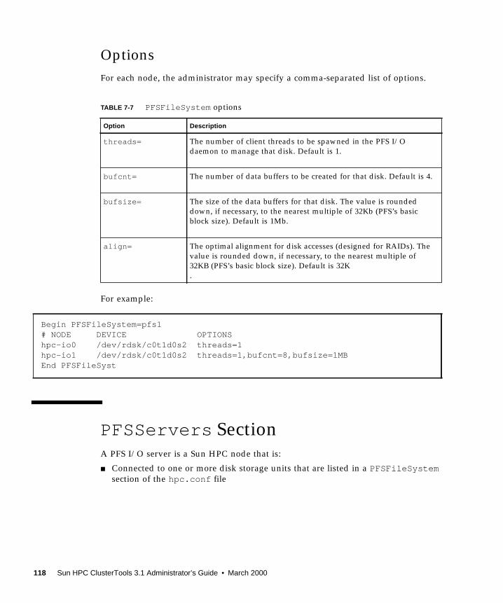
Options
For each node, the administrator may specify a comma-separated list of options.
For example:
PFSServers SectionA PFS I/O server is a Sun HPC node that is:
■ Connected to one or more disk storage units that are listed in a PFSFileSystemsection of the hpc.conf file
TABLE 7-7 PFSFileSystem options
Option Description
threads= The number of client threads to be spawned in the PFS I/O
daemon to manage that disk. Default is 1.
bufcnt= The number of data buffers to be created for that disk. Default is 4.
bufsize= The size of the data buffers for that disk. The value is rounded
down, if necessary, to the nearest multiple of 32Kb (PFS’s basic
block size). Default is 1Mb.
align= The optimal alignment for disk accesses (designed for RAIDs). The
value is rounded down, if necessary, to the nearest multiple of
32KB (PFS’s basic block size). Default is 32K
.
Begin PFSFileSystem=pfs1# NODE DEVICE OPTIONShpc-io0 /dev/rdsk/c0t1d0s2 threads=1hpc-io1 /dev/rdsk/c0t1d0s2 threads=1,bufcnt=8,bufsize=1MBEnd PFSFileSyst
118 Sun HPC ClusterTools 3.1 Administrator’s Guide • March 2000

■ Listed in the PFSServers section of hpc.conf , as shown in TABLE 7-6
In addition to being defined in hpc.conf , a PFS I/O server also differs from other
nodes in a Sun HPC cluster in that it has a PFS I/O daemon running on it.
Nodes
The left column lists the hostnames of the nodes that are PFS I/O servers. In this
example, they are ios0 through node2 and node3 .
TABLE 7-8 PFSServers Section Example
Begin PFSServersNODE OPTIONSnode0node1node2node3End PFSServers
Chapter 7 hpc.conf Configuration File 119

Options
For each node, the administrator may specify a comma-separated list of options.
For example:
TABLE 7-9 PFSServer options
Option Description
threads= The number of threads to be spawned to handle client
requests. Default is 5.
nbufs= The amount of memory the PFS I/O daemon will have for
buffering transfer data, specified in units of 32-Kbyte buffers.
Default is 64.
clntcong={yes | no} Turn on (or turn off) congestion control on the client side.
This option and the next cause PFS to regulate carefully the
load it places on the network and on particular interfaces.
They are intended to be used with networks (or NICs) that do
not degrade gracefully under heavy load. In most cases, there
is a performance penalty for setting this option to yes. Default
is no.
servcong={yes | no} Turn on (or turn off) congestion control on the server side.
This option and the previous cause PFS to regulate carefully
the load it places on the network and on particular interfaces.
They are intended to be used with networks (or NICs) that do
not degrade grace fully under heavy load. In most cases, there
is a performance penalty for setting this option to yes. Default
is no.
Begin PFSServers# NODE OPTIONShpc-io0 nbufs=32hpc-io1 nbufs=32End PFSServers
120 Sun HPC ClusterTools 3.1 Administrator’s Guide • March 2000

HPCNodesSectionThis section is used only in a cluster that is using LSF as its workload manager, not
CRE. The CRE ignores the HPCNodessection of the hpc.conf file.
Propagating hpc.conf InformationWhenever hpc.conf is changed, the CRE database must be updated with the new
information. After all required changes to hpc.conf have been made, restart the
CRE master and nodal daemons as follows:
# /etc/init.d/sunhpc.cre_master start# /etc/init.d/sunhpc.cre_node start
If PFS file systems were unmounted and PFS I/O daemons were stopped, restart the
I/O daemons and remount the PFS file systems. See Chapter 4 for guidance.
Chapter 7 hpc.conf Configuration File 121

122 Sun HPC ClusterTools 3.1 Administrator’s Guide • March 2000

CHAPTER 8
Troubleshooting
This chapter describes some procedures you can use for preventive maintenance and
troubleshooting. The topics covered are:
■ Cleaning up defunct CRE jobs
■ Using diagnostics
■ Interpreting error messages
■ Anticipating common problems
■ Recovering from system failure
Cleaning Up Defunct CRE JobsOne preventive maintenance practice that can be beneficial is the routine cleanup of
defunct jobs. There are several types of such jobs:
■ Jobs that have exited, but still appear in mpps output
■ Jobs that have not terminated, but need to be removed
■ Jobs that have orphan processes
Removing CRE Jobs That Have Exited
When a job does not exit cleanly, it is possible for all of a job’s processes to have
reached a final state, but the job object itself to not be removed from the CRE
database. The following are two indicators of such incompletely exited jobs:
■ A process (identified by mpps) in the EXIT , SEXIT , FAIL , or COREstates
■ A Prism main window that will not close or exit
123

If you see a job in one of these defunct states, perform the following steps to clear
the job from the CRE database:
1. Execute mpps –e again in case the CRE has had time to update the database (andremove the job).
2. If the job is still running, kill it, specifying its job ID.
% mpkill jid
● If necessary, remove the job object from the CRE database.
If mpps continues to report the killed job, use the –C option to mpkill to remove the
job object from the CRE database. This must be done as root, from the master node.
# mpkill –C jid
Removing CRE Jobs That Have Not Terminated
The second type of defunct job includes jobs that are waiting for signals from
processes on nodes that have gone off line. The mpps utility displays such jobs in
states such as RUNNING, EXITING , SEXTNG, or CORNG.
Note – If the job-killing option of tm.watchd (–Yk) is enabled, the CRE will handle
such situations automatically. This section assumes this option is not enabled.
Kill the job using:
% mpkill jid
There are several variants of the mpkill command, similar to the variants of the
Solaris kill command. You may also use:
% mpkill –9 jid
or
% mpkill –I jid
If these do not succeed, execute mpps –pe to display the unresponsive processes.
Then, execute the Solaris ps command on the each of the nodes listed. If those
processes still exist on any of the nodes, you can remove them using kill –9 pid.
Once you have eliminated all defunct jobs, data about the jobs may remain in the
CRE database. As root from the master node, use mpkill –C to remove this residual
data.
124 Sun HPC ClusterTools 3.1 Administrator’s Guide • March 2000

Killing Orphaned Processes
When the tm.watchd –Yk option has been enabled, the watch daemon marks
processes ORPHANif they run on nodes that have gone off line. If the node resumes
communication with the CRE daemons, the watch daemon will kill the ORPHANprocesses. If not, you will have to kill the processes manually using the Solaris killcommand. Otherwise, such processes will continue to consume resources and CPU
cycles.
Symptoms of orphaned processes can be detected by examining error log files or
stdout , if you are running from a terminal. You can also search for such errors as
RPC: cannot connect , or RPC: timout . These errors will appear under user.errpriority in syslog .
Note – If an mprun process becomes unresponsive on a system, even where
tm.watchd –Yk has been enabled, it may be necessary to use Ctrl-c to kill mprun .
Using DiagnosticsThe following sections describe Solaris diagnostics that may be useful in
troubleshooting various types of error conditions.
Using Network Diagnostics
You can use /usr/sbin/ping to check whether you can connect to the network
interface on another node. For example:
% ping hpc-node3
will test (over the default network) the connection to hpc-node3 .
You can use /usr/sbin/spray to determine whether a node can handle significant
network traffic. spray indicates the amount of dropped traffic. For example:
% spray –c 100 hpc-node3
sends 100 small packets to hpc-node3 .
Chapter 8 Troubleshooting 125

Checking Load Averages
You can use mpinfo –N or, if the CRE is not running, /usr/bin/uptime , to
determine load averages. These averages can help to determine the current load on
the machine and how quickly it reached that load level.
Using Interval Diagnostics
The diagnostic programs described below check the status of various parameters.
Each accepts a numerical option that specifies the time interval between status
checks. If the interval option is not used, the diagnostics output an average value for
the respective parameter since boot time. Specify the numerical value at the end of
the command to get current information.
Use /usr/bin/netstat to check local system network traffic. For example:
% netstat –n i 3
checks and reports traffic every 3 seconds.
Use /usr/bin/iostat to display disk and system usage. For example:
% iostat –c 2
displays percentage utilizations every 2 seconds.
Use /usr/bin/vmstat to generate additional information about the virtual
memory system. For example:
% vmstat –S 5
reports on swapping activity every 5 seconds.
It can be useful to run these diagnostics periodically, monitoring their output for
multiple intervals.
Interpreting Error MessagesThis section presents sample error messages and their interpretations.
■ The following error message usually indicates that all the nodes in a CRE
partition are marked down—that is, their node daemons are not running:
No nodes in partition satisfy RRS:
126 Sun HPC ClusterTools 3.1 Administrator’s Guide • March 2000

■ Under certain circumstances, when a user attempts to kill a job, the CRE may log
error messages of the following form on the master node:
Aug 27 11:02:30 ops2a tm.rdb[462]: Cond_set: unable to connectto ops2a/45126: connect: Connection refused
If these can be correlated to jobs being killed, these errors can be safely ignored. One
way to check this correlation would be to look at the accounting logs for jobs that
were signaled during this time.
■ The following error message indicates that no partitions have been set up:
mprun: unique partition: No such object
■ When there is stale job information in the CRE database, an error message of the
following form may occur:
Query returned excess results:a.out: (TMTL UL) TMRTE_Abort: Not yet initializedThe attempt to kill your program failed.
This might happen, for example, when mpps shows running processes that are
actually no longer running.
Use the mpkill –C nn command to clear out such stale jobs.
Note – Before removing the job’s information from the database, the mpkill –Coption verifies that the processes of the job are in fact no longer running.
Anticipating Common ProblemsThis section presents some guidelines for preventing and troubleshooting common
problems.
■ When running multiprocess jobs (–np equal to 0 or greater than 1) in a cluster
with NFS-mounted file systems, you should take steps to limit core dumps to
zero. This can be done with the Solaris limit command. See the limit(1) man
page for additional information.
■ The CRE resource database daemon (tm.rdb ) does not remove missing interfaces
after a client daemon is restarted. Instead, the mpinfo –Nv command will show
them marked as down.
Chapter 8 Troubleshooting 127

■ The contents of the /var/adm/messages file are local to each node. Any
daemon messages will be logged only on the node where that daemon runs. By
default, CRE daemon messages are stored in /var/adm/messages along with
other messages handled by syslog . Alternatively, CRE messages can be written
to a file specified by the mpadmin logfile command.
■ Use shell I/O redirection instead of mprun –I options whenever possible. Using
shell redirection will reduce the likelihood of problems involving standard I/O.
■ If mprun is signaled too soon after it has been invoked, it exits without stopping
the job‘s processes. If this happens, use mpkill –9 jid to kill such a job.
■ The CRE does not pass supplemental group ID information to remote processes.
You must use the –G gid option with mprun to run with the group permissions of
that group. You must be a member of that group.
■ CRE RPC timeouts in Sun MPI code are logged to syslog , but the default
syslog .conf file causes these messages to be dropped. If you want to see these
errors, you should modify your /etc/syslog.conf file so that messages of the
priority user.err are not dropped. Note that this does not apply to RPC
timeouts occurring in the CRE daemons themselves. By default, these are logged
to /var/adm/messages .
Note – If you have set the Cluster-level attribute logfile , all error messages
generated by user code will be handled by the CRE (not syslog ) and will be logged
in a file specified by an argument to logfile .
CRE RPC timeouts in user code are generally not recoverable. The job might
continue to run, but processes probably will not be able to communicate with each
other. There are two ways to deal with this:
■ Enable the tm.watchd job killing option (–Yk), which will automatically kill jobs
when nodes go off line. This will catch most of these cases, since RPC timeouts
usually coincide with tm.watchd marking the node as off line.
■ Monitor RPC errors from user codes by looking for syslog messages of priority
user.err . Then use mpkill to kill the associated job manually.
■ If a file system is not visible on all nodes, users can encounter a permissiondenied message when attempting to execute programs from such a file system.
Watch for errors caused by non-shared file systems like /tmp , which exist locally
on all nodes. This can show up when users attempt to execute programs from
/tmp , and the program does not exist in the /tmp file systems of all nodes.
■ If the behavior of your system suggests that you have run out of swap space (after
executing vmstat or df on /tmp ), you may need to increase the limit on the
CRE’s shmem_minfree attribute.
■ If you execute mpkill with the –C option (this option is available only to the
system administrator), you should look for and remove leftover files on the
master node. The file names for large files are of the form:
128 Sun HPC ClusterTools 3.1 Administrator’s Guide • March 2000

/tmp/.hpcshm_mmap. jid.*
Smaller files will have file names of the form:
/tmp/.hpcshm_acf. jid.*
The Sun MPI shared memory protocol module uses these files for interprocess
communication on the same node. These files consume swap space.
Recovering From System FailureRecovering from system failure involves rebooting the CRE and recreating the CRE
resource database.
The cre.master reboot and cre.node reboot commands should be used only
as a last resort, if the system is not responding (for example, if programs such as
mprun , mpinfo , or mpps hang). Follow these steps to reboot the CRE:
● Run cre.master reboot on the master node.
# /etc/init.d/cre.master reboot
● Run cre.node reboot on all the nodes (including the master node if it isrunning tm.spmd and tm.omd ).
# /etc/init.d/cre.node reboot
The procedure will attempt to save the system configuration (in the same way as
using the mpadmin dump command), kill all the running jobs, and restore the system
configuration. Note that the Cluster Console Manager applications may be useful in
executing commands on all of the nodes in the cluster simultaneously. For
information about the Cluster Console Manager applications, see Appendix A.
Note – rte.master reboot saves the existing rdb-log and rdb-save files in
/var/hpc/rdb–log.1 and /var/hpc/rdb–save.1 . The rdb-log file is a
running log of the resource database activity and rdb-save is a snapshot of the
database taken at regular intervals.
Chapter 8 Troubleshooting 129

To recover CRE after a partial failure, that is, when some but not all daemons have
failed, it is possible to clean up bad database entries without losing the configuration
information. You can flush the dynamic data while preserving the configuration by
executing these commands:
(The start command is necessary in case some of the daemons are not running.)
# /etc/init.d/sunhpc.cre_master start# /etc/init.d/sunhpc.cre_master reboot
130 Sun HPC ClusterTools 3.1 Administrator’s Guide • March 2000

APPENDIX A
Cluster Console Tools
This appendix describes a set of cluster administration tools that are installed with
the Sun HPC ClusterTools 3.1 release.This toolset, called the Cluster Console
Manager, allows you to issue commands to all nodes in a cluster simultaneously
through a graphical user interface. The CCM offers three modes of operation:
■ cconsole – This interface provides access to each node’s console port through
terminal concentrator links. To use this tool, the cluster nodes must be connected
to terminal concentrator ports and those node/port connections must be defined
in the hpc_config file. See the Sun HPC ClusterTools 3.1 Installation Guide for
details.
■ ctelnet – This interface initiates simultaneous telnet sessions over the
network to all nodes in the cluster. Note that if passwords are required, every
node must be able to accept the same password.
■ crlogin – This interface uses rlogin to log you in to every node in the cluster.
Note that if you launch crlogin while logged in as superuser, all rloginsessions will be done as superuser. Likewise, if crlogin is launched from an
ordinary user prompt, all remote logins will be done as user.
Each of these modes creates a command entry window, called the Common Window,
and a separate console window, called a Term Window, for each node. Each command
typed in the Common Window is echoed in all Term Windows (but not in the
Common Window). Every Term Window displays commands you issue as well as
system messages logged by its node.
Note – If the cluster nodes are not connected to a terminal concentrator (for
example, the Sun Ultra HPC 10000 has no provision for a terminal concentrator),
only ctelnet and crlogin can be used, not cconsole .
131

Launching Cluster Console ToolsAll Cluster Console tools are launched using the same command-line form:
% tool_name cluster_name
where tool_name is cconsole , ctelnet , or crlogin , and cluster_name is a name
given to the cluster. The default cluster name is hpc_cluster , which is established
automatically when cluster_tool_setup is executed. For example,
■ Launch ctelnet by entering:
% ctelnet hpc_cluster
■ Launch crlogin by entering:
% crlogin hpc_cluster
■ Launch cconsole by entering:
% cconsole hpc_cluster
If you want to use cconsole to monitor messages generated while rebooting the
cluster nodes, you will need to launch it from a machine outside the cluster. If you
launch it from a cluster node, it will be disabled when the node from which it is
launched reboots.
Note – Because cconsole accesses the console ports of every node in the cluster, no
other accesses to any console in the cluster will be successful while the cconsolesession is active.
Note that all three Cluster Console commands take the standard X/Motif command-
line arguments.
Common WindowThe Common Window is the primary window used by the system administrator to
send input to all the nodes. This window has a menu bar with three menus and a
text field for command entry. The Common Window is always displayed when the
Cluster Console is launched.
132 Sun HPC ClusterTools 3.1 Administrator’s Guide • March 2000

The Common Window menu bar has three menus:
■ Hosts
■ Options
■ Help
Note that in this manual, the Cluster Console term Hosts refers to Sun HPC Cluster
nodes.
Hosts Menu
The Hosts menu displays a list of the nodes contained in the cluster, plus two other
entries, Select Hosts and Exit. TABLE A-1 describes these menu choices.
Select Hosts Dialog
The Select Hosts dialog enables you to add or delete nodes during the current
Cluster Console session. The scrolled text window in the Select Hosts dialog
displays a list of the nodes that are currently connected to the Cluster Console.
TABLE A-1 Cluster Console Menu Entries
Entry Function
Host toggle
buttons
Selects whether or not the host gets input from the Common Window
text field. There is a separate toggle button for each node currently
connected to the Cluster Console.
ON — Enables input from the Common Window text field to the node.
OFF — Disables input from the Cluster Console.
Select Hosts Displays the Select Hosts dialog window.
Exit Quits the Cluster Console program.
Appendix A Cluster Console Tools 133

There are three Select Hosts dialog buttons, which are described in TABLE A-2
.
▼ Adding a Single Node
1. Enter the hostname in the Hostname text field.
2. Select Insert.
Entering a valid host name opens a Term Window for the specified host and
establishes a connection to that host. The name of the selected host appears in the
scrolled text window and in the hosts list on the Hosts menu in the Common
Window.
▼ Adding All Nodes in a Cluster
1. Enter the clustername in the Hostname text field.
2. Select Insert.
The Cluster Console automatically expands the cluster name into its constituent host
names and then opens one Term Window for each node. A connection is established
for each of the constituent host names. The Cluster Console automatically displays
the names of the hosts in the cluster in the scrolled text window and in the hosts list
on the Hosts menu in the Common Window.
▼ Removing a Node
1. Select the name of the host in the list in the scrolled text window.
2. Select Remove.
This closes the corresponding Term Window and disconnects the host. The name of
the removed host disappears from the scrolled text window and from the hosts list
on the Hosts menu in the Common Window.
TABLE A-2 Select Hosts Dialog Buttons
Entry Function
Insert Opens a Term Window and establishes a connection to the specified
hosts(s). Adds the host(s) specified in the Hostname text field to the list
of accessible hosts. The inserted host name(s) are displayed in the hosts
list in the scrolled text window and in the Common Window.
Remove Deletes the host selected in the Hosts list in the scrolled text window.
Dismiss Closes the Select Hosts dialog.
134 Sun HPC ClusterTools 3.1 Administrator’s Guide • March 2000

Options Menu
The Options menu has one entry, Group Term Window; see TABLE A-3 for a
description.
Help Menu
The Help menu has three entries; see TABLE A-4 for a description
.
Text FieldThe text field is where you enter commands that you want to have executed
simultaneously on multiple nodes. The state of the host toggle buttons under the
Hosts menu determines which nodes receive this input.
TABLE A-3 Group Term Window Entry
Entry Function
Group Term
Windows
This is a toggle button that groups and ungroups the Common Window
and the Term Window.
ON — Group; the Term Windows follow the Common Window when the
Common Window is moved.
OFF — Ungroup: the Term Windows and the Common Window move
independently.
TABLE A-4 Help Menu
Entry Function
Help Displays a Help window—the interface to the Sun online help system.
About Displays the About box, which contains information on the Cluster
Console application, such as version number.
Comments Displays the Comments box, which allows you to enter comments about
the software and send them to the development team.
Appendix A Cluster Console Tools 135

Term WindowsThe Term Window is just like a normal terminal window. To type on only one host,
move the cursor to the Term Window of the desired host and type directly into it.
The Cluster Console Term Windows are like other terminal programs, such as
xterm , cmdtool , and shelltool , except that they can also receive input from the
Common Window. The Term Windows use VT220 terminal emulation.
The environment variable TERMinforms your editor of your terminal type. If you are
having display problems from vi or any other tools, set the environment variable
using the appropriate commands for your shell.
The Term Window contains additional functionality, which you can access by
positioning the pointer over the Term Window and pressing the right mouse button.
This displays the menu described in TABLE A-5
.
Using the Cluster ConsoleTo issue commands to multiple nodes simultaneously:
● Position the cursor in the text field of the Common Window and enter yourcommand.
Every keystroke entered in this field is sent to all hosts that are currently selected for
input.
To issue commands to a single node:
TABLE A-5 Term Window Menu Entries
Entry Function
Disable/Enable
Scroll Bar
Toggles the scroll bar display on and off in the Term Window.
Exit This
Window
Closes the current Term Window.
136 Sun HPC ClusterTools 3.1 Administrator’s Guide • March 2000

● Position the cursor in the corresponding Term Window and enter your command.
Alternatively, you can turn off all hosts in the Hosts menu, except the one you want
to access. Then issue your commands from the Common Window.
Administering Configuration FilesTwo configuration files are used by Cluster Console: clusters and serialports .
These files are created automatically by cluster_tool_setup , which places them
in /etc .
The clusters File
The clusters configuration file maps a cluster name to the list of hostnames that
make up the cluster Each line in this database corresponds to a cluster. The format is:
clustername hostname–1 hostname–2 [...] hostname–n
For example:
cities chartres izmir tampico inchon essen sydney
The clusters file is used to map cluster names to host names on the command line
and in the Select Hosts dialog.
The serialports File
The serialports file maps each host name to the terminal concentrator and the
terminal concentrator serial port to which it is connected. Each line in this database
specifies a separate serial port using the format:
hostname terminal_concentrator serial_port
For example:
chartres cities-tc 5002
izmir cities-tc 5003
The serialports file is used by cconsole to determine which terminal
concentrator and serial ports to connect to for the various cluster nodes that have
been specified on the command line or the Select Hosts dialog.
Appendix A Cluster Console Tools 137

138 Sun HPC ClusterTools 3.1 Administrator’s Guide • March 2000

APPENDIX B
Using the Command Line to Installand Remove ClusterTools 3.1
The easiest way to configure and install Sun HPC ClusterTools 3.1 software is to use
the configuration tool, install_gui , as described in the Sun HPC ClusterTools 3.1Installation Guide. If you can’t (or prefer not to) use install_gui , you may install
the software from the command line as described in this appendix.
FIGURE B-1 shows the principal steps involved in installing the ClusterTools 3.1
software, including verifying that system requirements are met before starting the
installation and verifying the success of the installation after the installation is
complete. The pre- and post-installation tasks are described in the Sun HPCClusterTool 3.1 Installation Guide, Chapters 2 and 5, respectively.
This appendix includes instructions for
■ Editing the cluster configuration file, hpc_config : “Accessing and Editing
hpc_config” on page 141
■ If using the cluster-tool installation method: “Run cluster_tool_setup” on
page 148
■ Installing the ClusterTools software at the command line: “Installing ClusterTools
3.1” on page 150
■ Removing the software: “Removing ClusterTools 3.0 or 3.1” on page 151
■ Removing and installing individual packages: “Removing and Reinstalling
Individual Packages” on page 152
■ Selecting which ClusterTools version will be active, 3.0 or 3.1: “Selecting the
Active ClusterTools Version” on page 152
■ Adding or removing nodes in an existing cluster: “Adding/Removing Nodes in
an Existing Cluster” on page 153
139

FIGURE B-1 Installing Sun HPC ClusterTools 3.1 Software, Task Summary
Edit
BeforeInstallation
Ensure that requirements are met.
See Chapter 5 of the
See Chapter 2 of the installation
Post-Installation
Create a cluster configuration fileusing the supplied template.
guide for a list of prerequisites.
installation guide.
Install ClusterTools 3.1 software.
Set UpCluster Tools
Set up Cluster Console Manager(CCM) tools.
hpc_configfile
Finishing Up
Install ClusterTools,and Various Other
Related Tasks
Remove ClusterTools 3.0 or 3.1 software.Install/remove individual packages.Select active ClusterTools version.Add/remove nodes from cluster.
140 Sun HPC ClusterTools 3.1 Administrator’s Guide • March 2000

Preparing for InstallationBefore installing Sun HPC ClusterTools 3.1 software, you need to ensure that the
hardware and software that make up your cluster meet certain requirements.
Requirements are outlined in Chapter 2 of the Sun HPC ClusterTools 3.1 InstallationGuide. Review them before proceeding with the instructions in this appendix.
Accessing and Editing hpc_configMany aspects of the Sun HPC ClusterTools 3.1 installation process are controlled by
a configuration file called hpc_config . Instructions for accessing and editing
hpc_config are provided in this section.
hpc_config Template
A template for hpc_config is provided on the Sun HPC ClusterTools distribution
CD-ROM to simplify creation of this file. The hpc_config template is located in
/cdrom/hpc_3_1_ct/Product/Install_Utilities/config_dir/hpc_config
Before starting the installation process, you should
■ Choose a node to serve as the installation platform
■ Copy the hpc_config template to a directory on that node
■ Edit the template so that it satisfies your site-specific installation requirements
The resulting hpc_config file must be located in a directory within a file system
that is mounted with read/write/execute permissions (chmod = 777) on all the other
nodes in the cluster.
Accessing the hpc_config Template
To access hpc_config on the distribution CD-ROM, perform the following steps on
the node chosen to be the installation platform:
1. Mount the CD-ROM path on all the nodes in the cluster.
2. Load the Sun HPC ClusterTools 3.1 distribution CD-ROM.
Appendix B Using the Command Line to Install and Remove ClusterTools 3.1 141

3. Copy the configuration template onto the node. In the following example,
config_dir_install represents a directory that you have chosen to be the location
where the configuration files will reside. All cluster nodes must be able to read
from and write to this directory.
4. Edit the hpc_config file according to the instructions provided in the next
section.
Editing hpc_config
FIGURE B-2 shows the basic hpc_config template, but without most of the comment
lines provided in the online template. The template is simplified here to make it
easier to read and because each section is discussed in detail following FIGURE B-2.
The template comprises five sections:
■ Supported Software Installation – All installations must complete this first section.
■ General installation information – All installations must complete this section. If you
are installing the software locally on a single-node cluster, you can stop after
completing this section.
■ Information for NFS and cluster-local installations – If you are installing the software
either on an NFS server for remote mounting on client nodes or locally on each
node of a multinode cluster, you need to complete this section.
■ Information for NFS installations – Complete this section only if you are installing
the software on an NFS server.
■ List of nodes from which ClusterTools software is to be removed – Use this section when
you want to remove ClusterTools software from one or more nodes. List the host
names of those nodes in this section.
# cd config_dir_install# cp /cdrom/hpc_3_1_ct/Product/Install_Utilities/config_dir/hpc_config .
142 Sun HPC ClusterTools 3.1 Administrator’s Guide • March 2000

FIGURE B-2 hpc_config Template (With Most Comment Lines Removed)
# Section I - Supported Software Information
# Do you want to run HPC 3.1 ClusterTools software with LSF software?LSF_SUPPORT=”<choice>”
# Part A: Running HPC 3.1 ClusterTools software with LSF software.
# Do you want to modify LSF parameters to optimize HPC job launches?MODIFY_LSF_PARAM=”<choice>”# Specify the name of the LSF Cluster.LSF_CLUSTER_NAME=”<clustername>”
# Part B: Running HPC 3.1 ClusterTools software without LSF software.
# Supply Master NodeMASTER_NODE=”<hostname>”# AuthenticationAUTHENTICATION=”<choice>”CREATE_REMOTE_AUTH_FILE=”<choice>”
# Section II - General Installation Information
# Type of Installation ConfigurationINSTALL_CONFIG=”<choice>”# Installation LocationINSTALL_LOC=”/opt”# CD-ROM Mount PointCD_MOUNT_PT=”/cdrom/hpc_3_1_ct”
# Section III - For Cluster-Local and NFS Installation
# Installation MethodINSTALL_METHOD=”<method>”# Hardware InformationNODES-”<hostname1> <hostname2> <hostname3>”
# Section IV - For NFS Installation
# NFS ServerNFS_SERVER=””# Location of the Software Installed on the NFS ServerINSTALL_LOC_SERVER=””
# Section V - Removing Nodes
# Enter the name of the nodes from which the ClusterTools will be removed.REMOVE_NODES=””
Appendix B Using the Command Line to Install and Remove ClusterTools 3.1 143

Section I – Supported Software Installation
This section must be completed for all installations.
LSF Support
If you will be using the CRE for resource management, enter no and proceed directly
to Part B of this section. If you will be using LSF, enter yes and then fill in Part A.
Part A: Running ClusterTools With LSF Software
If your cluster will be running LSF resource management software, specify whether
you want the installation script to modify certain LSF parameters to optimize HPC
job launching. For example:
Also, enter the name of the LSF cluster. This is an arbitrary name of your choice.
Part B: Running ClusterTools Without LSF Software
If your cluster will be using CRE for resource management, complete this part.
Specify the host name of the node that you want to serve as master node. The main
feature of this node is that it is the platform on which a set of master daemons run.
Also, specify your choice for authentication support. Your options are: DES (des ),
Kerberos 5 (krb5 ) or no authentication (none ).
LSF_SUPPORT="no"
MODIFY_LSF_PARAM="yes"
LSF_CLUSTER_NAME="hostname"
MASTER_NODE="hostname"
AUTHENTICATION="choice"
144 Sun HPC ClusterTools 3.1 Administrator’s Guide • March 2000

If you choose not to install any authentication (none ), you may elect to use a Sun
HPC authentication file by entering yes , as follows.
This will allow you to install a file named sunhpc_rhosts , which would contain a
list of remote hosts that are authorized to access the cluster.
If you enter no , your .rhosts file will be used for authentication. If you set
AUTHENTICATIONto krb5 or des , you must enter no in this field.
Section II – General Installation Information
This section must be completed for all installations. If you are installing the software
locally on a single-node cluster, you can stop after completing this section.
Type of Installation
Three types of installation are possible for Sun HPC ClusterTools:
■ nfs – Install the ClusterTools software on an NFS server for remote mounting on
client nodes.
■ smp–local – For single-node clusters only. Install the ClusterTools software
locally on this node for use only on this node.
■ cluster–local – For multinode clusters only. Install the ClusterTools software
locally on every node in the cluster.
Specify one of the installation types: nfs , smp–local , or cluster–local . There is
no default type of installation.
Installation Location
The way the INSTALL_LOC path is used varies, depending on which type of
installation you have chosen.
■ For local installations (smp–local or cluster–local ), INSTALL_LOC is the
path where the packages will actually be installed.
■ For NFS installations (nfs ), INSTALL_LOC is the mount point for the software on
the NFS clients.
CREATE_REMOTE_AUTH_FILE="yes"
INSTALL_CONFIG=" config_choice"
Appendix B Using the Command Line to Install and Remove ClusterTools 3.1 145

You must enter a full path name. The default location is /opt . Read/write
permissions must be set on all installation locations (or NFS mount points) on all the
nodes in the cluster.
If you choose an installation directory other than the default /opt , a symbolic link is
created from /opt/SUNWhpc to the chosen installation location/mount point.
CD-ROM Mount Point
Specify a mount point for the CD-ROM. This mount point must be mounted on (that
is, NFS-accessible to) all the nodes in the cluster. The default mount point is
/cdrom/hpc_3_1_ct . For example:
Section III – For Cluster-Local and NFS Installations
If you are installing the software either on an NFS server for remote mounting or
locally on each node of a multinode cluster, you need to complete this section.
Installation Method Options
Specify either rsh or cluster–tool as the method for propagating the installation
to all the nodes in the cluster.
■ cluster–tool – If you choose the cluster–tool option, you will be able to
use one of the Cluster Console Manager (CCM) applications, cconsole ,
ctelnet , or crlogin , to facilitate the installation of the ClusterTools software on
all of the nodes in parallel. See Appendix A for information about using CCM
tools.
■ rsh – If you choose the rsh method, the software will be installed serially on the
cluster nodes in the order in which they are listed in hpc_config . The CCM
applications cannot be used to install the software in rsh mode.
Also note that rsh requires that all nodes are trusted hosts—at least during the
installation process.
INSTALL_LOC="/opt"
CD_MOUNT_PT="/cdrom/hpc_3_1_ct"
INSTALL_METHOD="method"
146 Sun HPC ClusterTools 3.1 Administrator’s Guide • March 2000

Hardware Information
There are two ways to enter information in this section:
■ If the cluster nodes are connected to a terminal concentrator, list each node in the
following triplet format.
In each triplet, specify the host name of a node, followed by the host name of the
terminal concentrator and the port ID on the terminal concentrator to which that
node is connected. Separate the triplet fields with virgules (/). Use spaces between
node triplets.
■ If the cluster nodes are not connected to a terminal concentrator, simply list the
node host names, separated by spaces, as follows.
Section IV – For NFS Installations Only
Complete this section only if you are installing the software on an NFS server.
NFS Server Host Name
The format for setting the NFS server host name is the same as for setting the host
names for the nodes in the cluster. There are two ways to define the host name of the
NFS server:
■ If you have a terminal concentrator, describe the NFS server in the following
triplet format.
■ If you do not have a terminal concentrator, simply specify the host name of the
NFS server.
The NFS server can be one of the cluster nodes or it can be external (but connected)
to the cluster. If the server will be part of the cluster—that is, will also be an
execution host for the Sun HPC ClusterTools suite—it must be included in the
NODES="hostname1/termcon_name/port_id hostname2/termcon_name/port_id ..."
NODES="hostname1 hostname2 hostname3 ..."
NFS_SERVER="hostname/ termcon_name/ port_id"
NFS_SERVER="hostname"
Appendix B Using the Command Line to Install and Remove ClusterTools 3.1 147

NODESfield described in “Hardware Information” on page 147. If the NFS server
will not be part of the cluster, it must be available from all the hosts listed in NODES,but it should not be included in the NODESfield.
Location of the Software on the Server
If you want to install the software on the NFS server in the same directory as the one
specified in INSTALL_LOC, leave INSTALL_LOC_SERVERempty ("" ). If you prefer,
you can override INSTALL_LOC by specifying an alternative directory in
INSTALL_LOC_SERVER.
Recall that the directory specified in INSTALL_LOC defines the mount point for
INSTALL_LOC_SERVERon each NFS client.
Section V – Removing Nodes
When you want to remove ClusterTools 3.1 software from one or more nodes, list the
host names of the nodes in this section.
Use the same host name format as is used in the NODES="" section; that is, hostnameor hostname/termcon_name/portid.
Detailed instructions for removing nodes from a cluster are provided in “Removing
ClusterTools 3.0 or 3.1” on page 151.
Run cluster_tool_setupIf you have chosen the cluster–tool method of installation and plan to use the
CCM tools, you need to run the cluster_tool_setup script first. This loads the
CCM administration tools onto a node and creates a cluster configuration file that is
used by CCM applications. You must be root to run cluster_tool_setup .
See Appendix A for a description of the three CCM applications, cconsole ,
ctelnet , and crlogin .
INSTALL_LOC_SERVER="directory"
REMOVE_NODES=""
148 Sun HPC ClusterTools 3.1 Administrator’s Guide • March 2000

Note – cconsole requires the nodes to be connected to a terminal concentrator. The
others, ctelnet and crlogin , do not.
If you want to use cconsole to monitor messages generated while rebooting thecluster nodes, you will need to launch it from a machine outside the cluster. If you
launch it from a cluster node, it will be disabled when the node from which it is
launched reboots.
1. Go to the Install_Utilities directory on the Sun HPC ClusterTools 3.1distribution CD-ROM.
Note that this directory must be mounted on (accessible by) all nodes in the cluster.
2. If you are running on a node within the cluster, perform Step a. If you are runningon a machine outside the cluster, perform Step b.
a. Within the cluster, run cluster_tool_setup –c .
Run cluster_tool_setup ; use the –c tag to specify the directory containing
the hpc_config file.
b. Outside the cluster, run cluster_tool_setup –c –f .
Run cluster_tool_setup . Use the –c tag to specify the directory containing
the hpc_config file and the –f tag to force the installation to take place.
3. Set the DISPLAY environment variable to the machine on which you will berunning the CCM tools.
% suPassword: root_password# cd /cdrom/hpc_3_1_ct/Product/Install_Utilities
# ./cluster_tool_setup –c config_dir_install
# ./cluster_tool_setup –c config_dir_install –f
# setenv DISPLAY hostname:0
Appendix B Using the Command Line to Install and Remove ClusterTools 3.1 149

4. Invoke the CCM tool of your choice. If the nodes are connected to a terminalconcentrator, specify cconsole . If not, specify either ctelnet or crlogin .
All three tools reside in /opt/SUNWcluster/bin . For example,
All three CCM tools require the name of the cluster as an argument.
The CCM tool then creates a Common Window and separate Term Windows for all
the nodes in the cluster.
5. Position the cursor in the Common Window and press Return.
This activates a prompt in each Term Window. Note that the Common Window does
not echo keyboard entries. These appear only in the Term Windows.
You can now use CCM to install the software packages, as described in “Installing
ClusterTools 3.1” on page 150 or for removing ClusterTools software, either version
3.0 or 3.1, as described in “Removing ClusterTools 3.0 or 3.1” on page 151.
Installing ClusterTools 3.1This section describes the procedure for installing the Sun HPC ClusterTools 3.1
software. Note that the exact procedure for each step will depend on which
installation mode you are in, cluster-tool or rsh .
■ In cluster-tool mode, perform each step in the Common Window. Each entry
will be echoed in every Term Window.
■ In rsh mode, perform each step at the shell prompt of one of the nodes.
See Appendix A for more information about the CCM tools that are available to you
in cluster-tool mode.
Note – The hpc_install command writes various SYNCfiles in the directory
containing hpc_config as part of the package installation. If the installation process
stops prematurely. For example, if you press Ctrl–c , some SYNCfiles may be left.
You must remove these files before executing hpc_install again so they don’t
interfere with the next software installation session.
1. Log in to each node as root.
If you selected the cluster-tool installation method, you will need to know the
root password for each node.
# /opt/SUNWcluster/bin/ctelnet
150 Sun HPC ClusterTools 3.1 Administrator’s Guide • March 2000

2. Go to the Install_Utilities directory on the Sun HPC ClusterTools 3.1distribution CD-ROM.
Note that this directory must be mounted on all nodes in the cluster.
3. Run hpc_install .
where config_dir_install represents the directory containing the hpc_config file.
The –c tag causes hpc_install to look for a file named hpc_config in the
specified directory. If you want to install the software using a configuration file with
a different name, you must specify a full path including the new file name after the
–c tag.
Removing ClusterTools 3.0 or 3.1You can remove either version of the ClusterTools software, 3.0 or 3.1, by running
hpc_remove from a shell. The procedure for doing this is described below.
1. Locate the cluster configuration file, hpc_config .
Find the directory in which the hpc_config file resides. You will need to supply
this path on the hpc_remove command line in Step 4. If you cannot locate the
original hpc_config file, you will have to create one, as described in “Accessing
and Editing hpc_config” on page 141.
2. Place the Sun HPC ClusterTools 3.1 distribution CD-ROM in the CD-ROM drive.
3. Go to the Install_Utilities directory on the CD-ROM.
This directory must be mounted with read/execute permissions on all the nodes in
the cluster:
# cd /cdrom/hpc_3_1_ct/Product/Install_Utilities
# ./hpc_install –c config_dir_install
# cd /cdrom/hpc_3_1_ct/Product/Install_Utilities
Appendix B Using the Command Line to Install and Remove ClusterTools 3.1 151

4. Run hpc_remove ; use the –c option to specify the directory containing thehpc_config file and the –r option to specify the version of the software to beremoved.
The –c option causes hpc_remove to look for a file named hpc_config in the
specified directory. If you want to remove the software using a configuration file
with a different name, you must specify a full path including the new file name after
the –c option.
Enter either 3.0 or 3.1 as the version_number argument to –r .
Removing and Reinstalling IndividualPackagesTo remove a single package and install (or reinstall) another package in its place,
perform the following steps:
For example:
Selecting the Active ClusterTools VersionWhen both ClusterTools 3.0 and 3.1 are installed on a cluster, you can use
hpc_reconfigure to specify which version is to be active.
# ./hpc_remove –c config_dir_install –r version_number
# ./hpc_remove –c config_dir_install -d package_name# ./hpc_install –c config_dir_install -d package_name
# cd /cdrom/hpc_3_1_ct/Product/Install_Utilities# ./hpc_remove –c /home/hpc_admin –d SUNWs3l# ./hpc_install –c /home/hpc_admin –d /cdrom/hpc_3_1_ct/Product/SUNWs3l
152 Sun HPC ClusterTools 3.1 Administrator’s Guide • March 2000

1. Locate the cluster configuration file, hpc_config .
Find the directory in which the hpc_config file resides. You will need to supply
this path on the hpc_reconfigure command line in Step 4. If you cannot locate the
original hpc_config file, you will have to create one, as described in “Accessing
and Editing hpc_config” on page 141.
2. Place the Sun HPC ClusterTools 3.1 distribution CD-ROM in the CD-ROM drive.
3. Go to the Install_Utilities directory on the CD-ROM.
This directory must be mounted with read/execute permissions on all the nodes in
the cluster:
4. First, deactivate the version that you want to be inactive. To do this, runhpc_reconfigure , using the –c option to specify the directory containing thehpc_config file and the –d option to specify the ClusterTools version to bedeactivated.
5. Next, activate the other ClusterTools version. To do this, run hpc_reconfigureagain, using the –c option with the hpc_config file path and the –a option tospecify the ClusterTools version to be activated.
Adding/Removing Nodes in an ExistingClusterThis section describes the procedures for adding nodes to and removing nodes from
an existing cluster. It also explains how to remaster a cluster when a master node is
added or removed.
Note – These procedures do not support adding an NFS server to or removing it
from an existing cluster.
# cd /cdrom/hpc_3_1_ct/Product/Install_Utilities
# ./hpc_reconfigure –c config_dir_install –d version_number
# ./hpc_reconfigure –c config_dir_install –a version_number
Appendix B Using the Command Line to Install and Remove ClusterTools 3.1 153

Adding Nodes to an Existing Cluster
Perform the steps described below to add one or more nodes to an existing cluster.
Note – This procedure assumes that you will use the same installation method,
cluster-tools or rsh , as was used to install the ClusterTools 3.1 software
originally.
1. If you will be using the cluster-tool installation method, you need to take thefollowing steps first. If you will be using the rsh installation method, skip thisstep and go directly to Step 2.
a. Add the host name(s) of the new node(s) to the relevant cluster description inthe /etc/clusters file.
b. Add the node host name(s) and the applicable terminal concentrator host nameand port information to the /etc/serialports file.
2. Update the hpc_config file with the nodes being added.
Add the host names of the new nodes to the NODESfield of hpc_config . If you are
adding multiple nodes, they must be added as a contiguous block. See “Hardware
Information” on page 147 for a description of host names syntax in the NODESfield.
3. Update the cluster’s security facility. If your cluster uses either the DES orKerberos 5, update the authentication system to accommodate the new nodes.Otherwise, update the appropriate security files on each of the cluster nodes toreflect the new nodes, such as: /hosts.equiv , /etc/sunhpc_rhosts , and/.rhosts .
154 Sun HPC ClusterTools 3.1 Administrator’s Guide • March 2000

4. Execute the hpc_listnodes command to see where the new nodes are insertedinto the sorted list. Use the -c option to specify the configuration file containingthe node list.
If you are specifying the default configuration file hpc_config , name the directory
containing the hpc_config file. If specifying a configuration file with a customized
name, you must give the file’s full path name as the argument to -c .
The output generated by hpc_listnodes is a list of all the nodes contained in the
named configuration file’s NODESfield. Make a note of the positions of the first and
last new nodes in the list. These numbers will be needed in Step 5.
In the following example, three nodes are added to a cluster and their host names,
yellow_new , green_new , and blue_new , are inserted into the third, fourth, and
fifth positions in the NODESfield.
Therefore, the numbers to note are 3 and 5.
5. Execute /opt/SUNWhpc/bin/Install_Utilities/hpc_install on each of thenodes being added to the cluster.
Use the –c switch to specify the location of the configuration file. This could be
either the directory name containing the default configuration file hpc_config or
the full path name of the configuration file with the customized file name.
Use the –n switch to identify the new nodes, with the first and last position values
that you noted in Step 4 entered as the node_number_start and node_number_stoparguments.
For example, if you are using the default configuration file /usr/admin/hpc_config and if three nodes were added in positions 3, 4, and 5 of the NODESfield, the hpc_install command line should look like the this:
6. If one of the new nodes is to be the cluster’s new master node, perform the stepsdescribed in “Remastering the Cluster” on page 157.
# /opt/SUNWhpc/bin/Install_Utilities/hpc_install –c ( default_config_dir |full_pathname_of_custom_config)
NODES=”red_old orange_old yellow_new green_new blue_new purple_old”
# /opt/SUNWhpc/bin/Install_Utilities/hpc_install –c ( default_config_dir |full_pathname_of_custom_config) - n node_number_start: node_number_stop
# /opt/SUNWhpc/bin/Install_Utilities/hpc_install –c /usr/admin –n 3:5
Appendix B Using the Command Line to Install and Remove ClusterTools 3.1 155

7. If any of the new nodes will be PFS servers, do the following:
a. Update the /opt/SUNWhpc/conf/hpc.conf file on all PFS server and clientnodes to include the new PFS server(s).
b. Unmount the PFS file systems.
c. Stop and restart the PFS daemons. See Chapter 4 of this manual forinstructions.
8. If you want the new nodes to be included in partitions, use mpadmin to add themto the partitions of interest. See Chapter 6 in this manual for instructions.
Removing Nodes From an Existing Cluster
Perform the steps described below to remove one or more nodes from an existing
cluster.
1. If one of the nodes to be removed is the cluster’s master node, perform the stepsdescribed in “Remastering the Cluster” on page 157.
2. Update the REMOVE_NODESfield of the hpc_config file with the nodes beingremoved.
List the host names of the nodes to be removed in the REMOVE_NODESfield. See
“Section V – Removing Nodes” on page 148 for a description of the REMOVE_NODESfield.
3. Stop all CRE jobs running on the nodes that are to be removed.
4. If any of the new nodes to be removed are PFS servers, do the following:
a. Update the /opt/SUNWhpc/conf/hpc.conf file on all PFS server and clientnodes, deleting references to the PFS server(s) that will be removed.
b. Unmount the PFS file systems.
c. Stop and restart the PFS daemons. See Chapter 4 of this manual forinstructions.
156 Sun HPC ClusterTools 3.1 Administrator’s Guide • March 2000

5. Execute /opt/SUNWhpc/bin/Install_Utilities/hpc_remove on each of thenodes being removed from the cluster.
Use the –c switch to specify the location of the configuration file. This could be
either the directory name containing the default configuration file hpc_config or
the full path name of the configuration file with the customized file name.
Use the –r switch to specify which ClusterTools version is to be removed, 3.0 or 3.1.
For example:
6. If you are going to use cluster-tool method of removal, you need to take thefollowing steps first. If you will be using the rsh method, skip this step and go todirectly Step 7.
a. Delete the host name(s) of the node(s) that will be removed from the relevantcluster description in the /etc/clusters file.
b. Delete the node host name(s) and the applicable terminal concentrator hostname and port information from the /etc/serialports file.
7. Make the following changes to the configuration file.
a. Delete the host names from the REMOVE_NODESfield of the configuration file.
b. Delete the host names of the removed nodes from the NODESfield of theconfiguration file.
8. Update the cluster’s security facility to reflect the removal of the node(s). If eitherDES or Kerberos is used, update it as applicable. Otherwise, update the securityfiles on each of the cluster nodes to reflect the removal of the node(s). These mightinclude: /hosts.equiv , /etc/sunhpc_rhosts , and /.rhosts .
9. Use mpadmin to update partition descriptions to reflect node removal. See Chapter6 of this manual for instructions.
Remastering the Cluster
This section explains how to create a new master node for a cluster. This can happen
when a new node is made master node or when the current master node is removed
from a cluster.
When adding a new node that will be made master node, do the following after the
node is added to the cluster. When removing a current master node from a cluster,
do the following before the master node is removed.
1. Rename the current configuration file.
# /opt/SUNWhpc/bin/Install_Utilities/hpc_remove –c /usr/admin –r 3.1
Appendix B Using the Command Line to Install and Remove ClusterTools 3.1 157

2. Create a new configuration file in which the MASTER_NODEfield specifies the hostname of the new master node.
3. Stop all CRE jobs.
4. If your old configuration includes customized attributes that you would like toincorporate into the new configuration, use the mpadmin dump command to savethe cluster configuration information to a file.
5. Deactivate the cluster with the old master node. Do this by executing /opt/SUNWhpc/bin/Install_Utilities/hpc_reconfigure on each node in thecluster. Specify the same configuration that was used when the cluster wasoriginally configured.
Use the –c switch to specify the location of the old configuration file. This could be
either the name of the directory containing the default configuration file
hpc_config or the full path name of the configuration file with the customized file
name. In either case, the specification must be for the old configuration file.
Use the –d switch to specify the version of ClusterTools that is to be deactivated,
either 3.0 or 3.1. For example,
6. Flush the rdb on the old master node.
7. Activate the cluster with the new master node. Do this by executinghpc_reconfigure .
Use the –c switch to specify the location of the new configuration file. Use the –aswitch to specify which version of ClusterTools is to be activated, either 3.0 or 3.1.
For example:
8. If you saved the old configuration attributes to a file (as described in Step 4), youcan restore them now with the mpadmin -f option.
# mpadmin -c dump > file
# /opt/SUNWhpc/bin/Install_Utilities/hpc_reconfigure –c /usr/admin –d 3.1
# rm /var/hpc/rdb-log /var/hpc/rdb-save
# /opt/SUNWhpc/bin/Install_Utilities/hpc_reconfigure –c /usr/admin –a 3.1
# mpadmin - f file
158 Sun HPC ClusterTools 3.1 Administrator’s Guide • March 2000

APPENDIX C
Administering the LSF Plugins
A Sun HPC cluster may be configured to use the Load Sharing Facility (LSF) from
Platform Computing as its resource manager, as an alternative to the Sun CRE. For
this case, Sun HPC ClusterTools includes a set of plugins that allow other
ClusterTools components to operate with the LSF suite.
This appendix discusses various Sun HPC-specific administration issues for LSF-
based clusters. In particular, it describes hpc.conf , a Sun HPC configuration file
that extends the definition of Sun HPC system attributes beyond the parameters
defined in the LSF configuration files.
Before reading this guide, Sun HPC cluster administrators should read the LSF BatchAdministrators Guide, Version 3.2, which is supplied with the LSF software.
The LSF SuiteLSF Suite 3.2.3 is a collection of resource-management products that provide
distributed batch scheduling, load balancing, job execution, and job termination
services across a network of computers. The LSF products used by Sun HPC
ClusterTools software are: LSF Base, LSF Batch, and LSF Parallel.
■ LSF Base – Provides the fundamental services upon which LSF Batch and LSF
Parallel depend. It supplies cluster configuration information as well as the up-to-
date resource and load information needed for efficient job allocation. It also
supports interactive job execution.
■ LSF Batch – Performs batch job processing, load balancing, and policy-based
resource allocation.
■ LSF Parallel – Extends the LSF Base and Batch services with support for parallel
jobs.
159

Refer to the LSF Administrator’s Guide for a fuller description of LSF Base and LSF
Batch and to the LSF Parallel User’s Guide for more information about LSF Parallel.
LSF supports the concept of interactive batch execution of Sun HPC jobs as well the
conventional batch method. Interactive batch mode allows users to submit jobs
through the LSF Batch system and remain attached to the job throughout execution.
Sun HPC Configuration FileThe Sun HPC configuration file hpc.conf, defines attributes of Sun HPC clusters that
are not defined in any LSF configuration files. A single hpc.conf file is shared by all
the nodes in a cluster. It resides in the LSF shared directory LSF_SHARED_LOC.
Sun HPC ClusterTools software is distributed with an hpc.conf template, which you
can edit to suit your particular configuration requirements. The hpc.conf file
follows the formatting conventions of LSF configuration files. That is, each
configuration section is bracketed by a Begin/End keyword pair and, when a
parameter definition involves multiple fields, the fields are separated by spaces.
The hpc.conf file is organized into six sections. The first five pertain to all HPC
clusters, regardless of the resource manager used. The sixth section, HPCNodes,
pertains only to clusters configured with the LSF suite.
■ The ShmemResource section defines certain shared memory attributes.
■ The Netif section lists and ranks all network interfaces to which Sun HPC nodes
are connected.
■ The MPIQOptions section allows the administrator to control certain MPI
parameters by setting them in the hpc.conf file.
■ The PFSFileSystem section names and defines all parallel file systems in the
Sun HPC cluster.
■ The PFSServers section names and defines all parallel file system servers in the
Sun HPC cluster.
■ The HPCNodessection can be used to define an HPC cluster that consists of a
subset of the nodes contained in the LSF cluster.
Editing hpc.conf
When any changes are made to hpc.conf , the system should be in a quiescent state.
To ensure that it is safe to edit hpc.conf , shut down the LSF Batch daemons. See
Chapter 3 “Managing LSF Batch” in the LSF Batch Administrator’s Guide for
instructions on stopping and starting LSF Batch daemons.
160 Sun HPC ClusterTools 3.1 Administrator’s Guide • March 2000

Edit the first five sections of hpc.conf to suit the need of your cluster. These
sections are described above in this manual in Chapter 3 (briefly) and Chapter 7 (in
detail).
When editing the file’s MPIOptions section, note that there is an additional option
that pertains only to LSF-based clusters with an SCI interconnect. The option
rsm_links specifies (by number) which SCI interface(s) may be used for a given
queue.
The last section of hpc.conf , HPCNodes, allows you to define a Sun HPC cluster
that consists of a subset of the nodes contained in the LSF cluster. To use this
configuration option, enter the hostnames of the nodes that you want in the HPC
cluster in this section, one hostname per line. TABLE 8-1 shows a sample HPCNodessection with two nodes listed.
Propagating hpc.conf Information
Whenever hpc.conf is changed, the LSF daemons must be updated with the new
information. After all required changes to hpc.conf have been made, restart the
LSF base daemons LIM and RES. Use the lsadmin subcommands reconfig and
resrestert as follows:
hpc-demo# lsadmin reconfig
hpc-demo# lsadmin resrestart all
Then, use the badmin subcommands reconfig to restart mbatchd and hrestartto restart the slave batch daemons:
hpc-demo# badmin reconfig
hpc-demo# badmin hrestart all
This only needs to be done from one node. See the LSF Batch Administrator‘s Guidefor additional information about restarting LSF daemons.
TABLE 8-1 HPCNodesSection Example
Begin HPCNodesnode1node2End HPCNodes
Appendix C Administering the LSF Plugins 161

Creating Sun HPC–Specific QueuesBecause HPC jobs distribute multiple processes across multiple nodes, their batch
queue requirements are different from those of serial jobs. For this reason, you
should specifically configure one or more batch queues for running Sun HPC jobs.
This involves editing the queue configuration file, lsb.queues .
Specify PAM as Job Starter
The JOB_STARTERparameter allows an LSF batch queue to pass job launching
control over to a special job-starting procedure rather than launching the job itself.
For Sun HPC applications, this job launching role is given to the Parallel Application
Manager (PAM), which is a utility for starting and managing MPI jobs.
PAM should be specified as the job starter on all queues that will be used by Sun
HPC jobs. To do this, simply edit the JOB_STARTERline in lsb.queues to read as
follows:
JOB_STARTER=pam
When a Sun HPC job is submitted to a PAM-configured queue, the queue will start
PAM running. PAM, in turn, will launch the Sun HPC job on the cluster.
Enable Interactive Batch Mode
LSF supports the concept of interactive batch job execution. When a job is submitted
in interactive batch mode, it receives the same batch scheduling and host selection
services as noninteractive batch jobs, but the terminal from which the job was
submitted remains attached to the job as if it were launched interactively.
By default, both batch mode and interactive batch mode are available. To select
interactive batch mode, include the –I option on the bsub command line. Without
this option, bsub invokes conventional batch mode.
The INTERACTIVE parameter in the lsb.queues file allows you restrict a queue to
accept only interactive batch jobs or exclude all interactive batch jobs. Use it to restrict
Sun HPC–dedicated queues to interactive batch jobs. Otherwise, noninteractive jobs
could be added to the queue, which could make the queue less efficient for handling
the interactive batch jobs. To impose this restriction, add the following line to the
appropriate queue descriptor in the lsb.queues file:
162 Sun HPC ClusterTools 3.1 Administrator’s Guide • March 2000

INTERACTIVE=ONLY
All jobs submitted to a queue configured in this way must include the –I option on
the bsub command line.
Note – Separate queues can be configured for batch-mode–only jobs as well.
Because interactive batch jobs need fast response times, there are other steps you
should take to minimize job launch latencies normally associated with batch queue
behavior. These are described in the next section.
Configuring for Fast Interactive BatchResponse TimeThis section discusses several steps you can take to optimize the response time of an
interactive batch queue.
Set PRIORITY in lsb.queues
The PRIORITY parameter defines a batch queue’s priority relative to other batch
queues. To ensure faster dispatching, assign a higher PRIORITY value to interactive
batch queues than you give to noninteractive queues. A higher number equals a
higher priority. For example, the following setting
PRIORITY=12
means that jobs on that queue will usually be serviced sooner than jobs on queues
with a setting of PRIORITY=11 or lower.
Set NICE in lsb.queues
Set the queue’s NICE parameter to 10 . This will ensure that it receives the same CPU
priority as other interactive queues.
Appendix C Administering the LSF Plugins 163

Set NEW_JOB_SCHED_DELAYin lsb.queues
Set the NEW_JOB_SCHED_DELAYparameter to 0. This will allow a new job
scheduling session to be started as soon as a job is submitted to this queue.
Add Optimization Parameters to lsb.params
During installation of the Sun HPC ClusterTools packages, you are asked if you
want to modify the lsb.params file to optimize interactive batch response time. If
you answered yes , the SUNWrte package makes the following changes to the
lsb.params file:
MBD_SLEEP_TIME=1
MAX_SBD_FAIL=30
JOB_ACCEPT_INTERVAL=0
The first parameter, MBD_SLEEP_TIME, specifies the number of seconds LSF Batch
will wait between attempts to dispatch jobs. The default is 60 seconds. SUNWrtechanges the interval to 1 second.
The MAX_SBD_FAILparameter specifies how many times LSF Batch will try to reach
an unresponsive slave batch daemon before giving up. MBD_SLEEP_TIMEcontrols
the frequency of these attempts. If MAX_SBD_FAILis not specified, its default value
is three times the MBD_SLEEP_TIMEvalue. SUNWrte sets MAX_SBD_FAILto 30.
The JOB_ACCEPT_INTERVALparameter specifies how many MBD_SLEEP_TIMEperiods LSF Batch will wait after successfully dispatching a job to a host before it
dispatches another job to the same host. SUNWrte sets this parameter to 0, allowing
the host to accept multiple jobs in each job dispatching period (MBD_SLEEP_TIME).
If you answered no during the installation, but now wish to enable these
optimizations, simply edit these parameters in the lsb.params file as shown above.
Control of Queue Access to SCIInterfaces for RSM CommunicationIn the hpc-conf file, the administrator may enable or disable the availability of
Scalable Coherent Interface (SCI) network interfaces to communications that use the
Remote Shared Memory (RSM) protocol. This feature is useful for isolating the traffic
that originates from different types of jobs, say, development versus production or
benchmark jobs.
164 Sun HPC ClusterTools 3.1 Administrator’s Guide • March 2000

Note – Controlling the availability of an SCI interface for RSM communications
does not restrict the interface’s availability for other purposes.
The administrator lists SCI/RSM interfaces in the Netif section of the hpc.conf ,
each with a number appended. The STRIPE column may specify 1 or 0, indicating
that the interface is or is not available to queues for RSM communication.
Consider this example:
The interfaces scirsm1 and scirsm2 are available for use, whereas interfaces
scirsm0 and scirsm3 are not available for use.
The RSM daemon will load balance or stripe across multiple interfaces depending on
the stripe level requested and the number of interfaces available. If the total number
of interfaces available is greater than the stripe level requested, the connections will
be striped across the least loaded interfaces.
In addition to supporting numbered instances of a interface, hpc.conf also
supports the wildcard format (e.g., scirsm ), as in previous releases. The description
of a wildcard interface applies to all instances of that interface type except those that
are listed explicitly. For example, consider a situation where four SCI cards are
present and the hpc.conf entry looks like this:
The wildcard entry applies to instances 0 and 1, and makes them available for use by
RSM. Instances 2 and 3 will be unavailable.
Begin NetifNAME RANK MTU STRIPE PROTOCOL LATENCY BANDWIDTH...scirsm0 15 32768 0 rsm 20 150scirsm1 15 32768 1 rsm 20 150scirsm2 15 32768 1 rsm 20 150scirsm3 15 32768 0 rsm 20 150...End Netif
Begin NetifNAME RANK MTU STRIPE PROTOCOL LATENCY BANDWIDTH...scirsm 15 32768 1 rsm 20 150scirsm2 15 32768 0 rsm 20 150scirsm3 15 32768 0 rsm 20 150...End Netif
Appendix C Administering the LSF Plugins 165

The MPIOptions section of hpc.conf supports a new qualifier for queue options,
rsm_links . This is followed by a comma-separated list of scirsm instances,
indicating the interface instances to use for jobs on the specified queue. For example,
the following hpc.conf entry indicates that SCI/RSM interfaces 0, 1, and 2 may be
used by the queue performance .
Verifying Project-Based AccountingOne feature of LSF is project-based accounting—that is, individual jobs can be
associated with particular projects and charges allocated accordingly. Projects can be
specified in the following ways:
■ with the bsub option, –P proj_name, where proj_name is the name of the project.
■ with the environment variable LSB_DEFAULTPROJECT.
■ with the parameter DEFAULT_PROJECTin the lsb.params file.
A new, optional configuration variable, CHECK_PROJECT_UGRPMEMBERSHIP, has
been added to ensure the integrity of project-based accounting. To enable this
feature, add the following line to the lsb.params file:
CHECK_PROJECT_UGRPMEMBERSHIP=y
When this entry is present in lsb.params , the software verifies that the person
submitting the job is a member of the user group associated with proj_name. User
groups are defined in the configuration file lsb.users . If the person submitting the
job is not a member of the user group associated with that project, the job will be
rejected.
Begin MPIOptions queue=performance...rsm_links scirsm0, 1, 2End MPIOptions
166 Sun HPC ClusterTools 3.1 Administrator’s Guide • March 2000

Index
Aabbreviating commands, 85
accounting, 166
adding nodes, 153
administrative traffic
defined, 61
administrator attribute, 88, 90
attributes
changing, 75
node
cpu_idle , 91
cpu_iowait , 91
cpu_kernel , 91
cpu_type , 91
cpu_user , 91
enabled , 92, 93
load1 , 91
load15 , 91
load5 , 91
manufacturer , 91
master , 92
max_locked_mem , 92, 93
max_total_procs , 92
mem_free , 91
mem_total , 91
min_unlocked_mem , 92, 93
name, 92
ncpus , 91
offline , 91
os_arch_kernel , 91
os_name , 91
os_release , 91
os_release_maj , 91
os_release_min , 92
os_version , 92
partition , 92, 94
serial_number , 92
swap_free , 92
swap_total , 92
update_time , 92
partition, 98
enabled , 98, 101
max_locked_mem , 98
max_total_procs , 93, 98
min_unlocked_mem , 98
name, 98, 99
no_logins , 98, 99
no_mp_tasks , 98, 99
nodes , 98, 99
server-level
administrator , 88, 90
default_interactive_partition , 88
logfile , 88, 89
setting, 75, 76
system administrator-defined, 87, 102
authentication
DES, 39
Kerberos, 39
none, 39
authentication in PFS, 56
Bbandwidth, 63
batch queues, 162
167

Ccconsole , 131
cluster
defined, 8
Cluster Console Manager (CCM), 4, 131
Cluster context, 20, 72
cluster_tool_setup script, 148
cluster_tool_setup tool, 148
collocating applications and I/O daemons, 57
Common Window, 131, 132
compilers supported, 4
connectivity.c sample program, 12
context command, 78
core dumps, limiting, 127
cpu_idle attribute, 91
cpu_iowait attribute, 91
cpu_kernel attribute, 91
cpu_type attribute, 91
cpu_user attribute, 91
CRE
authentication methods, 39
concepts, 8
daemons, list of, 15
database, 38
job ID, 10
restarting, 13
starting, 10
stopping, 13
verifying setup, 12
cre.master reboot command, 129
cre.node reboot command, 129
cre_masterstart , 13
stop , 13
cre_nodestop , 13
create command, 74
crlogin , 131
ctelnet , 131
current command, 77
Ddaemons
tm.mpmd, 16
tm.omd , 17
tm.rdb , 15, 16
tm.spmd , 17
tm.watchd , 16
dedicated partitions, 97
default network
defined, 61
default partition, 11
default_interactive_partitionattribute, 88, 89
defunct jobs, 124
delete command, 74, 95
deleting
nodes, 95
partitions, 102
DES authentication, 40
df command, 53
diagnostics, 125
dirty file system, 55
Eecho command, 83
editing hpc.conf file, 28
enabled attribute, 92, 93, 101
partition, 98
enabled partition
defined, 8
enabling partitions, 101
/etc/vfstab , 52
external caches, 60
Fformatting configuration files, 160
fsck command, 55
Hhardware, 2
help command, 83
Hosts menu, 133
168 Sun HPC ClusterTools 3.1 Administrator’s Guide • March 2000
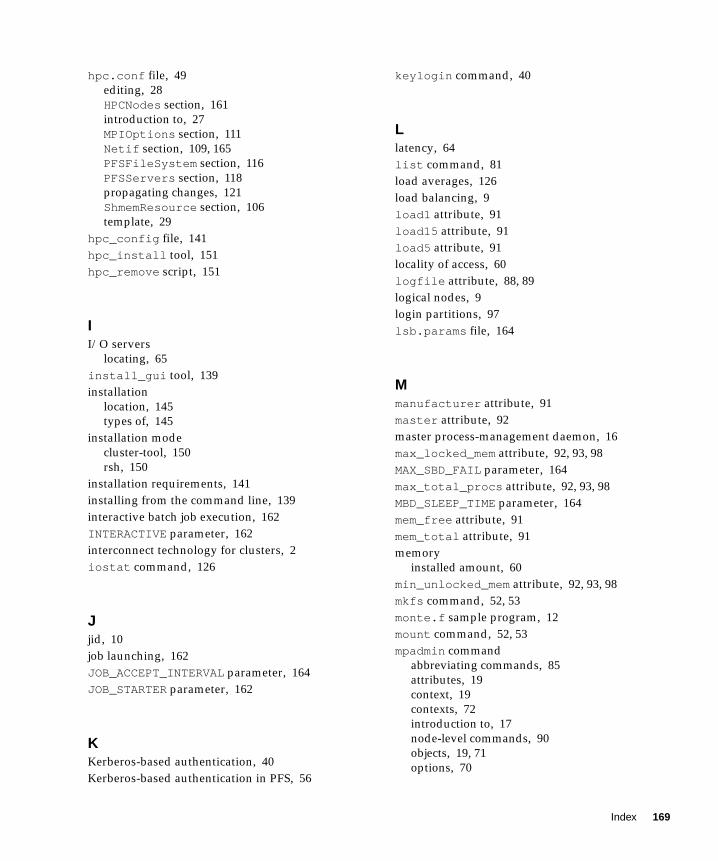
hpc.conf file, 49
editing, 28
HPCNodes section, 161
introduction to, 27
MPIOptions section, 111
Netif section, 109, 165
PFSFileSystem section, 116
PFSServers section, 118
propagating changes, 121
ShmemResource section, 106
template, 29
hpc_config file, 141
hpc_install tool, 151
hpc_remove script, 151
II/O servers
locating, 65
install_gui tool, 139
installation
location, 145
types of, 145
installation mode
cluster-tool, 150
rsh, 150
installation requirements, 141
installing from the command line, 139
interactive batch job execution, 162
INTERACTIVE parameter, 162
interconnect technology for clusters, 2
iostat command, 126
Jjid, 10
job launching, 162
JOB_ACCEPT_INTERVAL parameter, 164
JOB_STARTER parameter, 162
KKerberos-based authentication, 40
Kerberos-based authentication in PFS, 56
keylogin command, 40
Llatency, 64
list command, 81
load averages, 126
load balancing, 9
load1 attribute, 91
load15 attribute, 91
load5 attribute, 91
locality of access, 60
logfile attribute, 88, 89
logical nodes, 9
login partitions, 97
lsb.params file, 164
Mmanufacturer attribute, 91
master attribute, 92
master process-management daemon, 16
max_locked_mem attribute, 92, 93, 98
MAX_SBD_FAIL parameter, 164
max_total_procs attribute, 92, 93, 98
MBD_SLEEP_TIME parameter, 164
mem_free attribute, 91
mem_total attribute, 91
memory
installed amount, 60
min_unlocked_mem attribute, 92, 93, 98
mkfs command, 52, 53
monte.f sample program, 12
mount command, 52, 53
mpadmin command
abbreviating commands, 85
attributes, 19
context, 19
contexts, 72
introduction to, 17
node-level commands, 90
objects, 19, 71
options, 70
Index 169

partition-level commands, 96
prompts, 21, 73
quitting, 26
syntax, 69
MPI, 115, 116
MPI runtime options, 113
MPI_PROCBIND, 114
MPI_SHM_NUMPOSTBOX, 115
MPI_SPINDTIMEOUT, 114
mpkill command, 124
mprun command, 12
Nname attribute
node, 92
partition, 98, 99
naming attributes, 86
naming network interfaces, 86
naming nodes, 86
naming partitions, 86
naming queues, 86
naming, characters allowed in, 86
naming, restrictions, 86
ncpus attribute, 91
netstat command, 126
Network Interface context, 20, 72
NEW_JOB_SCHED_DELAY parameter, 164
NFS server host name, 147
NICE parameter, 163
no_logins attribute, 98, 99
no_mp_tasks attribute, 98, 99
node attributes
cpu_idle , 91
cpu_iowait , 91
cpu_kernel , 91
cpu_type , 91
cpu_user , 91
enabled , 92, 93
load1 , 91
load15 , 91
load5 , 91
manufacturer , 91
master , 92
max_locked_mem , 92, 93
max_total_procs , 92
mem_free , 91
mem_total , 91
min_unlocked_mem , 92, 93
ncpus , 91
offline , 91
os_arch_kernel , 91
os_name , 91
os_release , 91
os_release_maj , 91
os_release_min , 92
os_version , 92
partition , 92, 94
serial_number , 92
swap_free , 92
swap_total , 92
update_time , 92
Node context, 20, 72
nodes
adding, 154
defined, 8
deleting, 95
logical, 9
managing, 90
removing, 134, 148, 156
nodes attribute, 98, 99
Oobject monitoring daemon, 17
offline attribute, 91
orphaned processes, 125
os_arch_kernel attribute, 91
os_name attribute, 91
os_release attribute, 91
os_release_maj attribute, 91
os_release_min attribute, 92
os_version attribute, 92
PParallel Application Manager (PAM), 162
parallel application network
defined, 61
parallel I/O, 63
170 Sun HPC ClusterTools 3.1 Administrator’s Guide • March 2000

parallel partitions, 97
partial failures, 130
partition attribute, 92, 94
partition attributes, 98
enabled , 98, 101
max_locked_mem , 98
max_total_procs , 98
max_total_tasks , 93, 98
min_unlocked_mem , 98
name, 98, 99
no_logins , 98, 99
no_mp_tasks , 98, 99
nodes , 98, 99
Partition context, 20, 72
partitions
configuring, 97
dedicated, 97
default, 11
defined, 8, 11
deleting, 102
enabling, 101
login, 97
managing, 95
parallel, 97
serial, 97
shared, 97
viewing, 96
pbind , 114
PFS authentication, 56
PFS I/O daemon, 46, 51
PFS I/O server, 43
PFS kernel module, 47
PFS proxy daemon, 47, 51
PFS runtime library, 47
PFSFileSystem options, 50, 118
pfsmount PFS command, 53
PFSServer options, 120
PFSServers options, 51
pfsstart PFS command, 52
pfsstop PFS command, 55
pfsumount PFS command, 55
ping command, 125
PRIORITY parameter, 163
Prism environment, 3
Prism traffic, 62
progressadjust , 114
project-based accounting, 166
propagating configuration information, 161
RRAID Manager, 65
ratio of processors to processes, 59
recovering from system failure, 129
Remote Shared Memory (RSM), 164
removing ClusterTools software, 151
removing nodes, 148, 156
requirements for ClusterTools installation, 141
resource database daemon, 16
restarting the CRE, 13
restoring system configuration, 129
.rhosts , 39
rsm , 115
rsm_maxstripe , 115
rsm_shortmsgsize , 115
SScalable Coherent Interface (SCI), 2, 5, 164
Select Hosts dialog, 133
serial partitions, 97
serial_number attribute, 92
serialports file, 137
server-level attributes
administrator , 88, 90
default_interactive_partition , 88, 89
logfile , 88, 89
server-level mpadmin commands, 88
set command, 75, 76
shared partitions, 97
shm, 115
shm_numpostbox , 115
shm_shortmsgsize , 115
show command, 81
slave process-management daemon, 17
Solaris operating environments supported, 3
Solaris process ID, 10
spin, 116
spindtimeout , 114
Index 171

spray command, 125
start PFS command, 52
starting the CRE, 10
stop PFS command, 55
stopping the CRE, 13
Sun compilers supported, 4
Sun Enterprise Volume Manager, 65
Sun HPC System
hardware, 2
overview, 2
Sun MPI library, 3
Sun MPI traffic, 62
collective I/O operations, 63
Sun Scalable Scientific Subroutine Library (S3L), 4
sunhpc_rhosts file, 39
swap space
shared memory files, 60
swap_free attribute, 92
swap_total attribute, 92
Switch Management Agent, 5
symmetric multiprocessor (SMP), 8
TTerm Window, 131
tm.mpmd CRE daemon, 16
tm.omd CRE daemon, 17
tm.rdb CRE daemon, 15, 16
tm.spmd CRE daemon, 17
tm.watchd CRE daemon, 16
troubleshooting
/var/adm/messages file, 128
adjusting shmem_minfree attribute, 128
clean up leftover files, 128
connection refused messages, 127
lost CRE RPC timeout messages, 128
non-shared file systems, 128
shell I/O redirection, 128
supplemental group ID, 128
unique partition message, 127
Uumount command, 55
unresponsive processes, 124
up command, 78
update_time attribute, 92
Vverifying CRE setup, 12
viewing
existing partitions, 96
172 Sun HPC ClusterTools 3.1 Administrator’s Guide • March 2000