Embed Size (px)
Citation preview

Sunny Boy SB 3300TL HCTransformerless Solar Inverter
Installation Guide Version 1.0 SB3300TLHC-11:SE2306IME-SB33TLHC


SMA Technologie AG Table of Contents
Table of Contents1 Explanation of the Symbols Used . . . . . . . . . . . . 52 Foreword . . . . . . . . . . . . . . . . . . . . . . . . . . . . . . . 72.1 Target Group. . . . . . . . . . . . . . . . . . . . . . . . . . . . . 72.2 Appropriate Usage. . . . . . . . . . . . . . . . . . . . . . . . . 7
3 Safety Instructions . . . . . . . . . . . . . . . . . . . . . . . . 9
4 Overview. . . . . . . . . . . . . . . . . . . . . . . . . . . . . . 114.1 Unit Description . . . . . . . . . . . . . . . . . . . . . . . . . . 114.2 External dimensions . . . . . . . . . . . . . . . . . . . . . . . 12
5 Installation Requirements. . . . . . . . . . . . . . . . . . 135.1 Installation Site Requirements . . . . . . . . . . . . . . . . . 135.2 PV Generator Requirements . . . . . . . . . . . . . . . . . . 155.3 Low-voltage Grid (AC) . . . . . . . . . . . . . . . . . . . . . 15
6 Installation . . . . . . . . . . . . . . . . . . . . . . . . . . . . . 196.1 Mounting the Unit. . . . . . . . . . . . . . . . . . . . . . . . . 196.2 Electrical Installation . . . . . . . . . . . . . . . . . . . . . . . 206.2.1 Connecting the AC Output . . . . . . . . . . . . . . . . . . . . . . . . . . .226.2.2 PV String (DC) Connection . . . . . . . . . . . . . . . . . . . . . . . . . . .24
6.3 Commissioning . . . . . . . . . . . . . . . . . . . . . . . . . . . 25
7 Opening and Closing the Sunny Boy . . . . . . . . 277.1 Opening the Sunny Boy . . . . . . . . . . . . . . . . . . . . 277.2 Closing the Sunny Boy . . . . . . . . . . . . . . . . . . . . . 27
8 Technical Data . . . . . . . . . . . . . . . . . . . . . . . . . . 298.1 PV Generator Connection Data . . . . . . . . . . . . . . . 298.2 Grid Connection Data. . . . . . . . . . . . . . . . . . . . . . 308.3 General Data. . . . . . . . . . . . . . . . . . . . . . . . . . . . 318.4 Operating Parameters. . . . . . . . . . . . . . . . . . . . . . 33
Installation Guide SB3300TLHC-11:SE2306 Page 3
Table of Contents SMA Technologie AG
8.4.1 Explanation of the Operating Parameters . . . . . . . . . . . . . . . . .338.4.2 Parameter Settings for Germany . . . . . . . . . . . . . . . . . . . . . . .368.4.3 Country-specific Parameter Settings . . . . . . . . . . . . . . . . . . . . .378.4.4 Fixed Parameters . . . . . . . . . . . . . . . . . . . . . . . . . . . . . . . . . .38
8.5 Certificates. . . . . . . . . . . . . . . . . . . . . . . . . . . . . . 398.5.1 CE Declaration of Conformity . . . . . . . . . . . . . . . . . . . . . . . . .398.5.2 SMA Grid Guard Certificate . . . . . . . . . . . . . . . . . . . . . . . . . .40
9 Replacing the Varistors . . . . . . . . . . . . . . . . . . . 4110 Rating for a Line Circuit Breaker . . . . . . . . . . . . 45
11 The Communications Interface . . . . . . . . . . . . . . 4911.1 Connection RS232, RS485, Radio Piggy-Back. . . . . 5011.1.1 Jumper Functions . . . . . . . . . . . . . . . . . . . . . . . . . . . . . . . . . .51
11.2 Powerline Connection . . . . . . . . . . . . . . . . . . . . . . 52
12 Contact. . . . . . . . . . . . . . . . . . . . . . . . . . . . . . . . 57
Page 4 SB3300TLHC-11:SE2306 Installation Guide
SMA Technologie AG Explanation of the Symbols Used
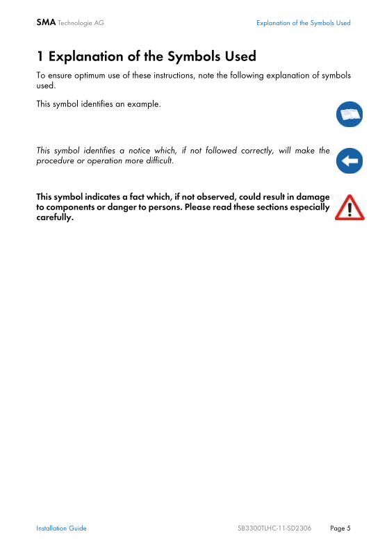
1 Explanation of the Symbols UsedTo ensure optimum use of these instructions, note the following explanation of symbolsused.
This symbol identifies an example.
This symbol identifies a notice which, if not followed correctly, will make theprocedure or operation more difficult.
This symbol indicates a fact which, if not observed, could result in damageto components or danger to persons. Please read these sections especiallycarefully.
Installation Guide SB3300TLHC-11-SD2306 Page 5
Explanation of the Symbols Used SMA Technologie AG
Page 6 SB3300TLHC-11-SD2306 Installation Guide

SMA Technologie AG Foreword
2 Foreword
Refer to the operating manual for detailed information on troubleshooting andoperating the Sunny Boy SB 3300TL HC. "Sunny Design" will assist you in the system design and checking the string size for agiven type of inverter. Further information on Sunny Design is available atwww.SMA.de.If you require further information, please call the Sunny Boy hotline on the followingnumber: (0561) 95 22 - 499
2.1 Target Group
This installation guide is exclusively intended for qualified electricians and is intendedto assist with the speedy and correct installation and setup of the SMA Sunny Boy SB3300TL HC inverter.
2.2 Appropriate Usage
The Sunny Boy SB 3300TL HC is equipped with the SMA grid guard. This is a typeof independent disconnection device. This means that the Sunny Boy SB 3300TLHC complies with the VDEW (Verband der Elektrizitätswirtschaft – GermanElectricity Industry Association) regulations for the connection and paralleloperation of electrical power units to the low-voltage grid of the electricity supplycompany and with DIN VDE 0126-1-1, which forms a part of these regulations.
Warning!The Sunny Boy may only be installed by trained specialists. Installers mustbe approved by the local energy supplier. Read this "installation guide"carefully. Ensure compliance with all prescribed safety regulations, thetechnical connection requirements of the local energy supplier and anyother applicable provisions.
Warning!The Sunny Boy SB 3300TL HC is designed for operation in grid-connectedPV systems. Any other use of the Sunny Boy SB 3300TL HC leads to lossof the the right to all warranty claims and may lead to a fault in the device.This includes, among other things, the operation at voltage sourceswithout any current limit. When in doubt, contact SMA.
Installation Guide SB3300TLHC-11-SD2306 Page 7

Foreword SMA Technologie AG
Page 8 SB3300TLHC-11-SD2306 Installation Guide

SMA Technologie AG Safety Instructions
3 Safety InstructionsWarning! Overvoltage!Check the system design using the "SunnyDesign" design tool (www.SMA.de) or bycalling the Sunny Boy Hotline.Overvoltages may lead to the destructionof the Sunny Boy SB 3300TL HC.
Warning! High voltage!Work on the Sunny Boy with the cover removed must be carried out by aqualified electrician. High contact voltages are present in the device. TheAC and DC voltages must be disconnected from the Sunny Boy and thecapacitors must be discharged before working on the Sunny Boy with thecover removed.The Sunny Boy must be disconnected from the mains grid and precautionsmust be taken to prevent the grid being accidentally reconnected. Inaddition, the connections to the PV generator must be disconnected.After isolating the AC and DC voltage, you must wait approx. 30 minutesfor the capacitors in the Sunny Boy to discharge. Only then is it safe toopen the unit by removing the cover and make sure that no voltage ispresent in the device.
Warning! Electrostatic charge!When working on the Sunny Boy SB 3300TL HC and handling itscomponents, remember to observe all ESD safety regulations. Electroniccomponents are susceptible to electrostatic charge. Discharge anyelectrostatic charge by touching the grounded housing before handlingany electronic component.
Installation Guide SB3300TLHC-11-SD2306 Page 9
Safety Instructions SMA Technologie AG
Page 10 SB3300TLHC-11-SD2306 Installation Guide
SMA Technologie AG Overview
4 Overview
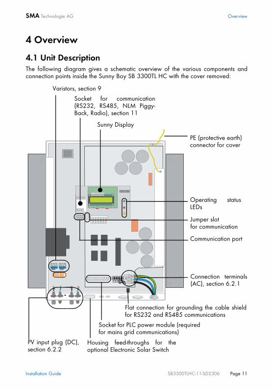
4.1 Unit DescriptionThe following diagram gives a schematic overview of the various components andconnection points inside the Sunny Boy SB 3300TL HC with the cover removed:
Varistors, section 9
Socket for communication(RS232, RS485, NLM Piggy-Back, Radio), section 11
Sunny Display
PE (protective earth) connector for cover
Operating statusLEDs
Jumper slotfor communication
Communication port
Connection terminals(AC), section 6.2.1
PV input plug (DC),section 6.2.2
Housing feed-throughs for theoptional Electronic Solar Switch
Socket for PLC power module (requiredfor mains grid communications)
Flat connection for grounding the cable shieldfor RS232 and RS485 communications
Installation Guide SB3300TLHC-11-SD2306 Page 11
Overview SMA Technologie AG
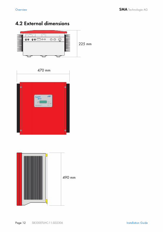
4.2 External dimensions
225 mm
470 mm
490 mm
Page 12 SB3300TLHC-11-SD2306 Installation Guide

SMA Technologie AG Installation Requirements
5 Installation RequirementsCheck that all of the conditions listed below are met before installing and setting up theSunny Boy.
5.1 Installation Site RequirementsThe Sunny Boy SB 3300TL HC weighs more than 28 kg. Take thisweight into account when choosing the installation site and methodof installation.
The Sunny Boy SB 3300TL HC is designed for outdoor installationand should be installed in a place where it is not exposed to directsunlight. An increased ambient temperature can reduce the yield ofthe PV system. Installing the unit in badly ventilated, warm indoorlocations may also reduce yield.
The Sunny Boy is designed to be mounted on a vertical wall. However, if absolutelynecessary, the Sunny Boy can be installed tilted back at a maximum angle of 45°.Vertical installation at eye-level is preferable for an optimum energy yield and maximumoperational comfort. If installing the unit outdoors, make sure that it is not slantingforward.We advise against installing the unit in a horizontal position outdoors.
The ambient temperature must not be outside the -25 °C to+60 °C range.
28 kg
Install the inverter vertically or tilting backward.
Never install the inverter horizontally or so that it tilts forward.
Installation Guide SB3300TLHC-11-SD2306 Page 13
Installation Requirements SMA Technologie AG
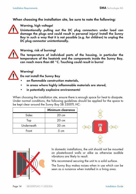
When choosing the installation site, be sure to note the following:
When choosing the installation site, ensure there is enough space for heat to dissipate.Under normal conditions, the following guidelines should be applied for the space tobe kept clear around the Sunny Boy SB 3300TL HC:
In domestic installations, the unit should not be mountedon plasterboard walls or alike as otherwise audiblevibrations are likely to result.We recommend securing the unit to a solid surface.The Sunny Boy makes noises when in use which can beseen as a nuisance when installed in a living area.
Warning, high voltage!Unintentionally pulling out the DC plug connectors under load candamage the plugs and could result in personal injury! Install the SunnyBoy in such a way that it is not possible (e.g. for children) to unplug theDC plug connector unintentionally.
Warning, risk of burning!The temperature of individual parts of the housing, in particular thetemperature of the heatsink and the components inside the Sunny Boy,can reach more than 60 °C. Touching could result in burns!
Warning!Do not install the Sunny Boy• on flammable construction materials,• in areas where highly inflammable materials are stored,• in potentially explosive environments!
Minimum clearance
Sides 20 cm
Top 20 cm
Underneath 20 cm
Front 5 cm
Page 14 SB3300TLHC-11-SD2306 Installation Guide

SMA Technologie AG Installation Requirements
5.2 PV Generator RequirementsThe Sunny Boy SB 3300TL HC is designed to be connected to up to two strings havinga homogenous structure (modules of the same type, identical orientation, tilt andnumber)."Sunny Design" will assist you in the system design and checking of the string size for agiven type of inverter. Further information on "Sunny Design" is available atwww.SMA.de.The unit has four DC plug connectors (two for each string) for connecting the PVgenerators. The connecting cables from the PV generators must also be fitted with thistype of plug connector. The SMA order codes for the various connectors are as follows:
5.3 Low-voltage Grid (AC)
The relevant technical regulations and the special instructions of the local grid operatormust be followed.The connection terminals of the Sunny Boy SB3300TL HC are suitable for wire cross-sections of upto 10 mm². The external diameter of the cable mustbe between 9 mm and 17 mm. The connection ismade with three wires (L, N, PE).
• Multi-Contact 3 mm: "SWR-MC"
• Multi-Contact 4 mm: "MC-SET"
• Tyco: "TYCO-SET"
Limit values for DC input
Max. voltage 750 V (DC)
Max. input current 11 A (DC)
Caution!The feed-in connection must be protectedby a 25 A circuit breaker type B. Nofurther devices must be connected to thesecured cable.
Installation Guide SB3300TLHC-11-SD2306 Page 15

Installation Requirements SMA Technologie AG
Rating for a Line Circuit Breaker in a Photovoltaic Electrical Power Unit Operated in Parallel with the Low-voltage gridVarious factors should be taken into account when selecting line circuit breakers. Theseinclude, for example:• The type of cable used (conductor material and insulation)• Ambient temperatures affect the cables (higher temperatures result in a reduced
maximum current load)• Method of routing the cable (reduces the maximum current load)• Bundling cables together (reduces the maximum current load)• Loop impedance [Z] (in the event of a body contact this limits the current that can
flow and therefore determines the response behavior of the circuit breaker)• Sufficient distance between the circuit breakers so as to avoid undue heating (heat
can trigger the circuit breaker early).• Selectivity• Protection class of the connected load (VDE 0100, part 410, "Protection against
electric shock")
Examples for rating a line circuit breaker are given in section 10 "Rating for a LineCircuit Breaker" (Page 45).
The Sunny Boy SB 3300TL HC is equipped with an integrated universal current sensitiveleakage-current breaker. The Sunny Boy SB 3300TL HC can automatically differentiatebetween real fault currents and "normal" capacitive leakage currents.
The following standards should be followed in all cases:
• DIN VDE 0298-4 (Cable routing and current-carrying capacity)
• DIN VDE 0100; part 430 (Protective measures "Protection of cables andcords against overcurrent")
• DIN VDE 0100; part 410 (Protective measures "Protection againstelectric shock")
A 30 mA RCD or FI circuit breaker must not be installed.
Page 16 SB3300TLHC-11-SD2306 Installation Guide

SMA Technologie AG Installation Requirements
The Sunny Boy SB 3300TL HC does not generate any extraordinary leakage currentsin normal operation. In certain operating states (e.g. during self-test of the protectiveequipment), leakage currents may occur which can trigger a "normal" 30 mA RCD orFI circuit breaker.
Line LossesAC cable system impedance should not exceed 1 ohm. This is necessary, amongst otherthings, for the correct operation of impedance observation. In addition, we recommenddimensioning the conductor cross-section so that line losses do not exceed 1 % at thenominal power. Line losses depending on the cable length and cross-section are shownin the graph below. Multi-wire cables with copper forward and return conductors areused.
The maximum cable lengths for the different cable cross-sections are as follows:
In case an RCD or FI circuit breaker is imperative, you must use a circuit breakerwith a sensitivity of 100 mA or more.
Cable cross-section 4.0 mm² 6.0 mm² 8.0 mm² 10.0 mm²
Max. length 18 m 28 m 37 m 47 m
Do not use cables where the losses will exceed 1.0 %
Cable length
Line
loss
es
Installation Guide SB3300TLHC-11-SD2306 Page 17

Installation Requirements SMA Technologie AG
The Sunny Boy SB 3300TL HC is designed for operation on 220 - 240 V grids at a gridfrequency of 50 Hz. When connecting an inverter to the public grid, follow theconnection requirements of the local grid operator.
Limit values for AC output
Voltage range(in the area of application of DIN VDE 0126-1-1)
198 V ... 253 / 260 V a
Frequency range(in the area of application of DIN VDE 0126-1-1)
47.55 Hz ... 50.2 Hz
Voltage range(extended operating range)
180 V ... 265 V
Frequency range(extended operating range)
45.5 Hz ... 54.5 Hz
a The Sunny Boy can feed into the public grid at a maximum output voltage of260 V for brief periods. According to DIN VDE 0126-1-1, however, the 10-minute average must not exceed a voltage of 253 V. That means, if the gridvoltage is constantly 254 V (e.g.), the inverter disconnects itself from the grid.In this case, contact the local grid operator for assistance. DIN VDE 0126-1-1 only applies in Germany. See section 8.4.3 "Country-specific Parameter Settings" (Page 37) for all other preset country values ofyour inverter.
Page 18 SB3300TLHC-11-SD2306 Installation Guide
SMA Technologie AG Installation
6 Installation
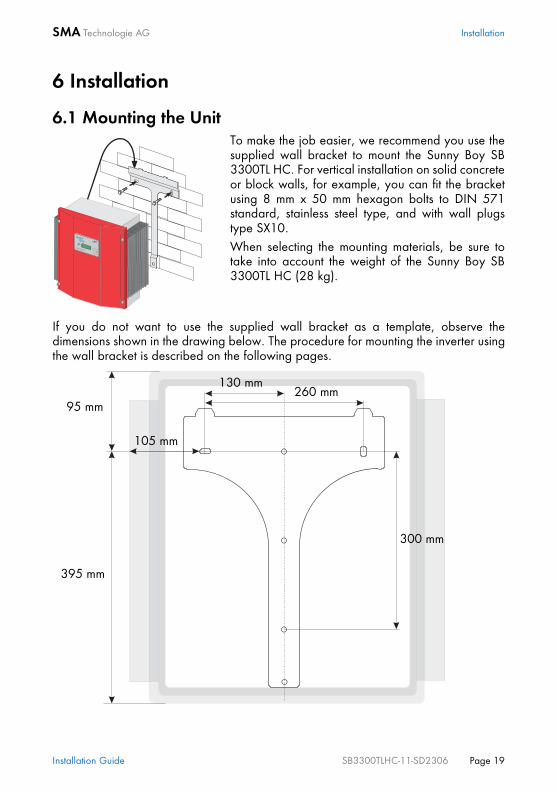
6.1 Mounting the UnitTo make the job easier, we recommend you use thesupplied wall bracket to mount the Sunny Boy SB3300TL HC. For vertical installation on solid concreteor block walls, for example, you can fit the bracketusing 8 mm x 50 mm hexagon bolts to DIN 571standard, stainless steel type, and with wall plugstype SX10. When selecting the mounting materials, be sure totake into account the weight of the Sunny Boy SB3300TL HC (28 kg).
If you do not want to use the supplied wall bracket as a template, observe thedimensions shown in the drawing below. The procedure for mounting the inverter usingthe wall bracket is described on the following pages.
300 mm
260 mm130 mm
105 mm
95 mm
395 mm
Installation Guide SB3300TLHC-11-SD2306 Page 19

Installation SMA Technologie AG
1. Fit the wall bracket (1). To mark the positions todrill the holes, you can use the wall bracket asa drilling template.
2. Now hang the Sunny Boy SB 3300TL HC ontothe wall bracket (2) using its upper mountingplate so that it cannot be moved sideways.
3. Secure the Sunny Boy SB 3300TL HC inposition by screwing the supplied M6x10 boltinto the central threaded hole at the bottom ofthe bracket (3).
4. Make sure that the Sunny Boy SB 3300TL HC ispositioned securely on the bracket.
6.2 Electrical Installation
The complete wiring for a Sunny Boy SB 3300TL HC is shown schematically in thefollowing diagram:
Warning!Make sure to check the polarity of the strings before connecting them!
String A (1)
Opening for optional communication AC connection, max. 10 mm²
String A (2)
Page 20 SB3300TLHC-11-SD2306 Installation Guide
SMA Technologie AG Installation
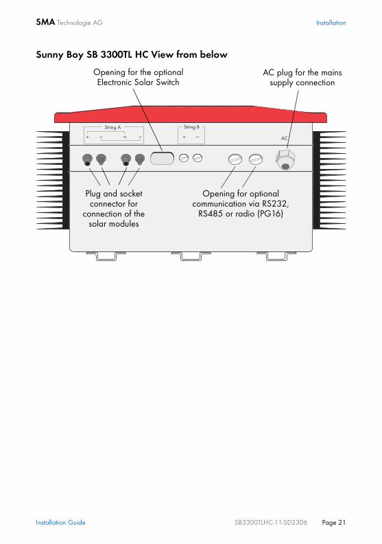
Sunny Boy SB 3300TL HC View from below
Plug and socket connector for
connection of the solar modules
Opening for the optional Electronic Solar Switch
AC plug for the mains supply connection
Opening for optional communication via RS232,
RS485 or radio (PG16)
Installation Guide SB3300TLHC-11-SD2306 Page 21

Installation SMA Technologie AG
6.2.1 Connecting the AC OutputTo connect the AC cable, proceed as follows: 1. Check the grid voltage. In the area of application of DIN VDE 0126-1-1, the
Sunny Boy will not be fully operational if the grid voltage is constantly higher than253 V. In this case, contact the local grid operator for assistance. The inverter cantemporarily feed power into the grid with a maximum output voltage of 260 V.However, the 10-minute average must not exceed 253 V.
2. Isolate the grid connection (switch the line circuitbreaker to its "off" position), make sure it cannotbe switched back on, and test to make sure novoltage is present.
3. Remove the screws that secure the housing of theSunny Boy SB 3300TL HC and carefully removethe cover. Remove the PE connection from thecover.
4. Connect the mains cable as shown in the figure.Use the supplied cable feed-through."L" and "N" must not be swapped.
Off!
L N
Page 22 SB3300TLHC-11-SD2306 Installation Guide

SMA Technologie AG Installation
6. Reconnect the PE connection to the housing cover. Fix the housing cover of theSunny Boy SB 3300TL HC and evenly tighten the four screws.
5. Connect the earth wire (PE) of the mains cable tothe upper screw terminal with the earth sign.
Warning!Correct operation of your Sunny Boy requires, among other things, theconnection of the PE conductor to the equipotential bonding of thebuilding. Check the prescribed PE connection from the Sunny Boy housingto protective earth when commissioning the device!
Warning!Do not switch the line circuit breaker on yet! The Sunny Boy SB 3300TL HCmay only be connected to the AC grid once the PV strings are connectedand the device is securely closed.
PE
Installation Guide SB3300TLHC-11-SD2306 Page 23
Installation SMA Technologie AG
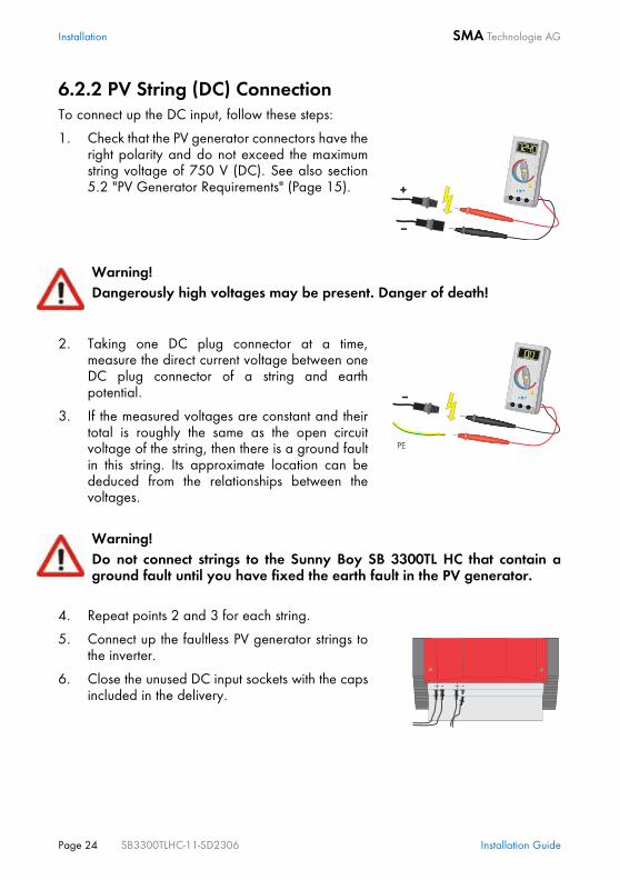
6.2.2 PV String (DC) ConnectionTo connect up the DC input, follow these steps:
1. Check that the PV generator connectors have theright polarity and do not exceed the maximumstring voltage of 750 V (DC). See also section5.2 "PV Generator Requirements" (Page 15).
Warning!Dangerously high voltages may be present. Danger of death!
2. Taking one DC plug connector at a time,measure the direct current voltage between oneDC plug connector of a string and earthpotential.
3. If the measured voltages are constant and theirtotal is roughly the same as the open circuitvoltage of the string, then there is a ground faultin this string. Its approximate location can bededuced from the relationships between thevoltages.
Warning!Do not connect strings to the Sunny Boy SB 3300TL HC that contain aground fault until you have fixed the earth fault in the PV generator.
4. Repeat points 2 and 3 for each string.
5. Connect up the faultless PV generator strings tothe inverter.
6. Close the unused DC input sockets with the capsincluded in the delivery.
Page 24 SB3300TLHC-11-SD2306 Installation Guide

SMA Technologie AG Installation
6.3 CommissioningYou can start up the Sunny Boy SB 3300TL HC when• the housing cover is securely screwed shut,• the AC (mains) cable is connected correctly,• the DC cables (PV strings) are fully connected and the unused DC plug connectors
on the bottom of the housing are closed using the protective caps.
How to Start up the Inverter
Check the string voltages again to make sure they are within the limits stated in section5.2 "PV Generator Requirements" (Page 15). If the string voltages are too high, contactthe planner / installer of the PV generator for assistance. If despite checking the string voltages the LED signal occurs again when the PVgenerator is connected to the Sunny Boy SB 3300TL HC, disconnect the PV generatorfrom the Sunny Boy again and contact SMA Technologie AG (see section 12 "Contact"(Page 57)).
1. First of all, switch the line circuit breaker to the"on" position.
2. Now look at the LED display and consult thetable on the following page to check whether theSunny Boy SB 3300TL HC is in a fault-free andexpedient operating mode. If this is the case,commissioning was successfully completed.
Warning! If the bottom yellow LED flashes four times at intervals of one second, thegrid voltage and the PV generator must be immediately disconnectedfrom the Sunny Boy SB 3300TL HC! There is a risk of damage to theinverter resulting from excessive DC input voltage.
On
Installation Guide SB3300TLHC-11-SD2306 Page 25

Installation SMA Technologie AG
For a detailed description of the fault messages and their causes, see the operatinginstructions.
Green Red Yellow Status
illuminates continuously
Is not illuminated is not illuminated OK (working mode)
illuminates continuously
is not illuminated fault
illuminates continuously
OK (initialization)
flashes quickly (3 x per second)
is not illuminated is not illuminated OK (stop)
illuminates continuously
is not illuminated fault
flashes slowly(1 x per second)
is not illuminated is not illuminated OK (waiting, grid monitoring)
illuminates continuously
is not illuminated fault
briefly goes out (approx. 1 x per
second)
is not illuminated is not illuminated OK (derating)
illuminates continuously
is not illuminated fault
is not illuminated is not illuminated is not illuminated OK (night shutdown)
illuminating/flashing fault
illuminates continuously
is not illuminated fault
illuminating/flashing fault
Page 26 SB3300TLHC-11-SD2306 Installation Guide

SMA Technologie AG Opening and Closing the Sunny Boy
7 Opening and Closing the Sunny Boy
7.1 Opening the Sunny Boy
1. Switch the line circuit breaker to the "off" position.2. Disconnect the PV generator from the Sunny Boy SB 3300TL HC.3. Wait 30 minutes!4. Remove the four screws from the housing cover and pull the cover forward
smoothly. At the same time remove the PE connection from the cover. Loosen thelocking on the PE connectors on the cover when you remove them.
7.2 Closing the Sunny Boy
1. Reconnect the earth wire (PE) to the housing cover. Now secure the housing coverof the Sunny Boy SB 3300TL HC by evenly tightening the four screws. The screwsmust be tightened with approximately 4 Nm torque in order to guarantee thesealing of the enclosure.
2. Connect the PV generator. Ensure the assignment of the strings is correct.3. Switch the line circuit breaker to the "on" position. 4. Now check whether the LED display on the Sunny Boy SB 3300TL HC indicates
that the device is functioning correctly.
Warning!If you need to open the device for whatever reason, pay attention tosection 3 "Safety Instructions" (Page 9).
Warning!Follow the sequence below under all circumstances.
Warning! Follow the sequence below under all circumstances.
Installation Guide SB3300TLHC-11-SD2306 Page 27

Opening and Closing the Sunny Boy SMA Technologie AG
Page 28 SB3300TLHC-11-SD2306 Installation Guide

SMA Technologie AG Technical Data
8 Technical Data
8.1 PV Generator Connection DataDescription Short
des.Setting
Max. input voltage a) UDC max 750 V
Input voltage, MPP range UPV 125 V ... 750 V
Max. input current IPV max 11 A
Max. input power PDC 3440 W
Voltage ripple Upp < 10 % of the input voltage
a) Ensure that the maximum input open circuit voltage, which can occur at a celltemperature of -10 °, does not exceed the maximum input voltage.
Installation Guide SB3300TLHC-11-SD2306 Page 29

Technical Data SMA Technologie AG
8.2 Grid Connection DataDescription Short
des.Setting
Nominal output power PACnom 3000 W
Max. output power PACmax 3300 W
Nominal output current IACnom 13 A
Harmonic distortion of output current (at KUgrid < 2 %, PAC > 0.5 PACnom)
KIAC < 4 %
Operating range, grid voltage UAC 180 ... 265 V AC Germany: 198 ... 253 / 260 V ACb)
Operating range, grid frequency fAC 45,5 ... 54.5 HzGermany: 47,55 ... 50.2 Hz
Phase shift angle (based on the current's fundamental frequency)
cos phi 1 (at nominal power output)
Overvoltage category III
Test voltage (50 Hz) 1.65 kV (1 s routine testing / 5 s type testing)
Test surge voltage 4 kV (1.2/50 ms) (serial interface: 6 kV)
b) The Sunny Boy can feed into the public grid at a maximum output voltage of260 V for brief periods. According to DIN VDE 0126-1-1, however, the 10-minute average must not exceed a voltage of 253 V. That means, if the gridvoltage is constantly 254 V (e.g.), the inverter disconnects itself from the grid.In this case, contact the local grid operator for assistance. DIN VDE 0126-1-1 only applies in Germany. See section 8.4.3 "Country-specific Parameter Settings" (Page 37) for all other preset country values ofyour inverter.
Page 30 SB3300TLHC-11-SD2306 Installation Guide
SMA Technologie AG Technical Data
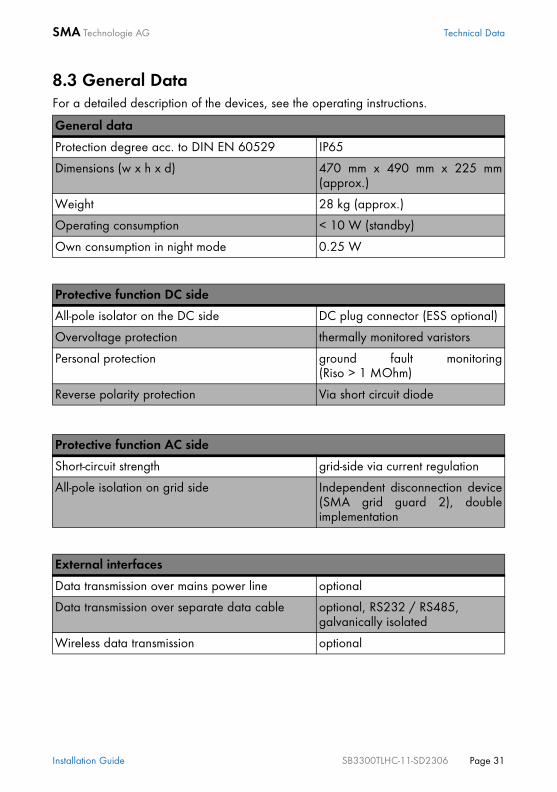
8.3 General DataFor a detailed description of the devices, see the operating instructions.
General data
Protection degree acc. to DIN EN 60529 IP65
Dimensions (w x h x d) 470 mm x 490 mm x 225 mm(approx.)
Weight 28 kg (approx.)
Operating consumption < 10 W (standby)
Own consumption in night mode 0.25 W
Protective function DC side
All-pole isolator on the DC side DC plug connector (ESS optional)
Overvoltage protection thermally monitored varistors
Personal protection ground fault monitoring(Riso > 1 MOhm)
Reverse polarity protection Via short circuit diode
Protective function AC side
Short-circuit strength grid-side via current regulation
All-pole isolation on grid side Independent disconnection device(SMA grid guard 2), doubleimplementation
External interfaces
Data transmission over mains power line optional
Data transmission over separate data cable optional, RS232 / RS485, galvanically isolated
Wireless data transmission optional
Installation Guide SB3300TLHC-11-SD2306 Page 31

Technical Data SMA Technologie AG
The efficiency of the Sunny Boy SB 3300TL HC depends mainly on the input voltage ofthe connected PV strings. The higher the input voltage, the higher the efficiency.
Efficiency
Max. efficiency ηmax 96 %
European standard efficiency ηeuro 94,6 %
Output power [W]
Ove
rall
effic
ienc
y [%
]
Page 32 SB3300TLHC-11-SD2306 Installation Guide

SMA Technologie AG Technical Data
8.4 Operating Parameters
8.4.1 Explanation of the Operating Parameters
Warning!Unauthorized changes to the operating parameters may result in:• injury or accidents as a result of changing the internal safety routines
in the Sunny Boy,• voiding the Sunny Boy's operating approval certificate,• voiding the Sunny Boy's guarantee.Never change the parameters of your Sunny Boy without expressauthorization and instructions.
Name Explanation
ACVtgRPro Voltage rise protection (only relevant for Germany).Sunny Boys can feed into the public grid in Germany with up to260 V AC. However, DIN VDE 0126-1-1 stipulates that theaverage AC voltage over 10 minutes must not exceed 253 V. Ifthe average over 10 minutes exceeds the threshold value of 253V, the inverter disconnects itself from the grid. Once the averageover 10 minutes returns to a value of less than 253 V, the inverterreturns to "Working" mode. If voltage rise protection is notrequired in the relevant grid area (outside Germany), it can bedeactivated by means of presetting the LDVtgC parameter. Inthis event, only the fast cut-off via the Uac-Max parameterintervenes.
AntiIsland-Ampl Amplification of the AntiIsland process (alternative AntiIslandingprocess, which is deactivated for Germany).
AntiIsland-Freq Repetition rate of the AntiIsland process (alternativeAntiIslanding process, which is deactivated for Germany).
Betriebsart /Operating Mode
Operating mode of the Sunny Boy:MPP: Maximum Power PointUKonst: Constant voltage mode (desired voltage is defined in"Usoll-Konst")IKonst: Operating mode for test purposesStopp: Disconnection from mains network, no operation
Installation Guide SB3300TLHC-11-SD2306 Page 33

Technical Data SMA Technologie AG
Default Used for setting the country specific-information.GER/VDE0126-1-1: Country-specific parameter settings forGermany in accordance with DIN VDE 0126-1-1IT/DK5940: Country-specific parameter settings for ItalyOther: Here, parameter settings can be defined for countries forwhich no predefined setting exists.Trimmed: If country-specific parameters have been changed,"trimmed" is shown in the display.
dFac-Max Maximum "grid frequency change" before the grid monitoringsystem disconnects the device from the grid.
dZac-Max Maximum "grid impedance change" before the grid monitoringsystem disconnects the device from the grid.
E_Total Total energy yield for the inverter. This change may benecessary when you replace the Sunny Boy and want to use thedata stored in the old device.
Fac-delta- Maximum frequency, above (Fac-delta+) and below (Fac-delta-)the grid frequency, before the grid monitoring systemdisconnects the device from the grid.
Fac-delta+
Fac-Tavg Averaging time of grid frequency gaging
Firmware-BFR Firmware version of the operation control unit (BFR)
Firmware-DC-BFS Firmware version of the DC operation control unit (DC-BFR)
FirmwareSRR Firmware version of the current control unit (SRR)
h_Total Total hours of operation for the inverter. This change may benecessary when you exchange the Sunny Boy and want to usethe data from the old device.
Hardware-DC-BFS Hardware version of the DC operation control unit (DC-BFR)
Inst.-Code Parameters for self contained power system recognition can onlybe changed after entering the "SMA grid guard" password.
Name Explanation
Page 34 SB3300TLHC-11-SD2306 Installation Guide

SMA Technologie AG Technical Data
LDVtgC Compensation for the voltage drop in the cabling.With this parameter, the voltage drop between the inverter andthe grid connection point is taken into account. The 10-minuteaverage voltage at the inverter connection must not exceed thesum of ACVtgRPro plus LDVtgC. The parameter LDVtgC is presetto 0 V for Germany. The parameter LDVtgC is preset to 50 V forgrid areas in which the additional voltage rise protection is notrequired (see parameter ACVtgRPro). Thus, the surge voltageprotection is deactivated for these grid areas (253 V + 50 V =303 V) and only the fast cut-off via the Uac-Max parameterintervenes.
NiTest Setting the impulse for impedance monitoring. This parameteronly functions when the Sunny Boy is deactivated (disconnectedon the AC side) or in "Stopp" mode.
Plimit Upper limit for AC output power
Ripple-Ctl-Frq The Ripple-Ctl-Frq, Ripple-Ctl-Lev, Ripple-Ctl-Rcvr parameters areintended to handle ripple control signals from the SMA inverters.These parameters are not available for all inverters. Theseparameters may only be changed after prior agreement withSMA Technologie AG.
Ripple-Ctl-Lev
Ripple-Ctl-Rcvr
Riso-Min Lower limit of the permitted insulation resistance
SMA-Grid-Guard SMA grid guard version number
SMA-SN Serial number of the Sunny Boy
Speicherfunkt. Default parameter: Returns all parameter values to the factorysetting.Reset Betriebsdaten: Returns all user level parameter values tothe factory setting.Reset Fehler: Resets a permanent fault.
T-Start The period the Sunny Boy waits after all switch-on conditionshave been satisfied.
Uac-Min Lower (Uac-Min) and upper (Uac-Max) limits of the allowableAC voltage (self contained power system recognition), beforethe grid monitoring system disconnects the device from the grid.
Uac-Max
Uac-Tavg Averaging time of grid frequency gaging
Uzwk-Start The DC voltage required before the Sunny Boy begins feedingpower into the mains supply.
Name Explanation
Installation Guide SB3300TLHC-11-SD2306 Page 35

Technical Data SMA Technologie AG
8.4.2 Parameter Settings for GermanyGrayed out parameters are only displayed in installer mode. The table below containsthe parameters that are applicable in Germany.
Usoll-Konst DC PV desired voltage for constant operational voltage. Theseparameters are only important when the "Betriebsart" parameteris set to U-konst.
Name Unit Value range Factory setting
ACVtgRPro V 230 ... 300 253
AntiIsland-Ampl * grd 0 ... 10 0
AntiIsland-Freq * mHz 0 ... 2000 500
Betriebsart MPP, IKonst,UKonst, Stopp
MPP
Default * GER/VDE0126-1-1, IT/DK5940,Other, trimmed
GER/VDE0126-1-1
dFac-MAX * Hz/s 0,1 ... 4,0 4,0
dZac-MAX * mOhm 350 ... 20000 700
E_Total kWh 0 ... 200000 0
Fac-delta- * Hz 0,1 ... 4,5 2,45
Fac-delta+ * Hz 0,1 ... 4,5 0,19
h_Total h 0 ... 200000 0
Ni-Test * 0 / 1 1
Inst.-Code
Ripple-Ctl-Rcvr enable, disable,auto
disable
Ripple-Ctl-Lev % 0,5 ... 8,00 1,70
Ripple-Ctl-Frq Hz 110 ... 1600 216,7
Riso-Min kOhm 1500 ... 30000 1500
Speicherfunktion DefaultParameter, ResetBetriebsdaten,Reset Fehler
None
Name Explanation
Page 36 SB3300TLHC-11-SD2306 Installation Guide

SMA Technologie AG Technical Data
8.4.3 Country-specific Parameter SettingsThe parameters listed below represent country-specific settings and are only displayedin installer mode. All other parameters are international and can be viewed in the tablein section 8.4.2.
T-Start * s 2 ... 300 2
Uac-Min * V 160 ... 230 198
Uac-Max * V 230 ... 300 260
Usoll-Konst DC V 0 ... 750 290
Parameters designated with * are safety-related grid monitoring parameters. Tochange the SMA grid guard parameters, you must enter you personal SMA gridguard password (Inst.-Code). Call the Sunny Boy Hotline to obtain your personalSMA grid guard password.
Name Unit Country settings
Germany Italy
Default GER/VDE0126-1-1 IT/DK5940
dFac-Max Hz/s 4,0 0,20
dZac-Max mOhm 700 350
Fac-delta- Hz 2,45 0,29
Fac-delta+ Hz 0,19 0,29
Ni-Test 1 0
T-Start s 2 2
Uac-Min V 198 198
Uac-Max V 260 260
Name Unit Value range Factory setting
Installation Guide SB3300TLHC-11-SD2306 Page 37

Technical Data SMA Technologie AG
8.4.4 Fixed ParametersThe following parameters are displayed in the parameter list but cannot be changed:
Name Unit Factory setting
Fac-Tavg ms 160
Firmware-DC-BFR
Hardware-DC-BFR
Plimit W 3300
SMA-Grid-Guard
SMA-SN
Software-BFR
Software-SRR
Uac-Tavg ms 80
Page 38 SB3300TLHC-11-SD2306 Installation Guide

SMA Technologie AG Technical Data
8.5 Certificates
8.5.1 CE Declaration of Conformity
SB-K
16A
-CE-
12:B
E170
6
SMA Technologie AGHannoversche Strasse 1-5 34266 NiestetalTel. +49 561 9522 – 0Fax +49 561 9522 – [email protected]
Product: Sunny BoyType: SB 700, SB 1100, SB 1100LV, SB 1700, SB 2100TL,
SB 2500, SB 2800i, SB 3000, SB 3300TL, SB 3300TL HCWe declare that the above specified devices are compliant with the regulations of the EuropeanCommunity, in terms of the design and the version fabricated by SMA. This especially appliesfor the EMC Regulation defined in 89/336/EWG and the LV- regulation defined in73/23/EWG.
The devices are compliant with the following standards:
EMC:Emission: DIN EN 61000-6-3: 2002-08
DIN EN 61000-6-4: 2002-08DIN EN 55022: 2003-09, Class B
Utility Interference: DIN EN 61000-3-3: 2002-05DIN EN 61000-3-2: 2001-12
Immunity: DIN EN 61000-6-1: 2002-08DIN EN 61000-6-2: 2002-08
Safety: DIN EN 50178: 1998-04Semiconductor-Converter: DIN EN 60146-1-1: 1994-03
The above mentioned devices are therefore marked with a CE sign.
Note:This declaration of conformity becomes invalid in case · the product is modified, complemented or changed,· and/or components, other than those belonging to the SMA accessories, are installed in the product,· as well as in case of incorrect connection or inproper usage without explicit written confirmation by SMA.
Niestetal, 13.03.2006
SMA Technologie AG
i.V. Frank Greizer(Head of Development Department Solar Technology)
for utility interactive inverters
CE Declaration of Conformity
Installation Guide SB3300TLHC-11-SD2306 Page 39
Technical Data SMA Technologie AG
8.5.2 SMA Grid Guard CertificateThe Sunny Boy is equipped with the independent disconnection device "SMA gridguard" and it is covered by the industrial trade association "SMA grid guard" importcertificate.
Page 40 SB3300TLHC-11-SD2306 Installation Guide

SMA Technologie AG Replacing the Varistors
9 Replacing the VaristorsThe Sunny Boy SB 3300TL HC is a complex high-technology device. As a result, thepossibilities for fixing faults on site are limited to just a few items. Do not attempt to carryout repairs other than those described here. Use the SMA Technologie AG 24-hourexchange service and repair service instead.If the red LED on the status display glows continuously during operation, you should firstof all make sure that there is no ground fault in the PV generator. Only skip points 3 to5 if the green LED is permanently lit at the same time.
4. If the measured voltages are constant and if their total is roughly the same as theopen circuit voltage of the string, then there is a ground fault in this string. Itsapproximate location can be deduced from the relationships between thevoltages.
5. Repeat points 3 and 4 for each string. 6. If you found a ground fault, it is probably not necessary to replace the varistors.
Instead, make sure the ground fault is fixed. Generally the PV generator'sinstallation engineer should be hired for this job. In this case continue as described
1. Disconnect the Sunny Boy SB 3300TL HC fromthe low-voltage grid (switch the line circuitbreaker to its "off" position). Make sure the gridcannot be inadvertently reconnected and test tomake sure no voltage is present at the AC output.
2. Disconnect the DC plug connectors for allstrings.
3. Taking one DC plug connector at a time,measure the voltages between one DC plugconnector of a string and earth potential. Payattention to the safety instructions!
Warning!Dangerously high voltages may be present. Danger of death!
Off!
Installation Guide SB3300TLHC-11-SD2306 Page 41

Replacing the Varistors SMA Technologie AG
under point 10, but without reconnecting the faulty string. Instead of reconnectingthe string, protect its DC plug against accidental touch contact (e.g. by fitting theprotective caps or using sufficient high-voltage insulating tape).If you did not find any ground fault in the PV generators, it is likely that one of thethermally monitored varistors has lost its protective function. These components arewearing parts. Their functioning diminishes with age or following repeatedresponses as a result of overvoltages. You can now check these varistors in thefollowing way, paying attention to the safety instructions in section 3 "SafetyInstructions" (Page 9):
7. Remove the screws that secure the cover and remove the cover from the SunnyBoy SB 3300TL HC. Disconnect the PE connection from the cover. Make sure thatno voltage is present.
8. Using a continuity tester, check all the varistors to see if there is a conductingconnection between connectors 2 and 3. If there is no connection, then thatvaristor is not working. The positions of the varistors in the Sunny Boy SB 3300TLHC can be seen in the figure in section 4.1 "Unit Description" (Page 11).
9. Replace the varistor concerned with a new oneas shown in the drawing to the right. Ensure thevaristor is installed the right way round! If you donot receive a special tool for operating theterminal clamps with your replacement varistors,contact SMA. As an alternative, the terminalcontacts can be operated using a suitablescrewdriver. Since the failure of one varistor isgenerally due to factors that affect all varistors ina similar way (temperature, age, inductiveovervoltages), it is highly recommended that youreplace all four varistors, not just the one that isobviously defective. The varistors are speciallymanufactured for use in the Sunny Boy SB3300TL HC and are not commercially available.They must be ordered directly from SMATechnologie AG (SMA order code: "MSWR-TV7").
Insert the special tool to open the
terminal
Remove the varistor
The pole with the small loop (crimp) must be fitted to
terminal 1 when replacing the varistor.
Page 42 SB3300TLHC-11-SD2306 Installation Guide

SMA Technologie AG Replacing the Varistors
If no ground fault and no defective varistor were found, there is probably a fault in theSunny Boy. In this case, contact the SMA hotline to discuss what to do next.
10. If no replacement varistors are available on site,the Sunny Boy SB 3300TL HC can temporarilyrun without them. To do this, remove the varistorsyou identified as being faulty and in their place,bridge the terminals 2 and 3 with a length ofwire.
The input modified in this way is no longer protected againstovervoltages! Replacement varistors should be obtained as soon aspossible. The Sunny Boy SB 3300TL HC should not be operated withoutvaristors in systems having a high risk of overvoltages!
11. Reconnect the PE connection on the cover and close the Sunny Boy SB 3300TLHC.
12. Connect up the faultless PV generator strings tothe inverter. Ensure the assignment of the stringsis correct.
13. Close the unused DC input sockets with the capsincluded in the delivery of the inverter.
14. Switch the line circuit breaker to the "on"position.
15. Now check whether the LED display on theSunny Boy SB 3300TL HC indicates that thedevice is functioning correctly.
On
Installation Guide SB3300TLHC-11-SD2306 Page 43
Replacing the Varistors SMA Technologie AG
Page 44 SB3300TLHC-11-SD2306 Installation Guide

SMA Technologie AG Rating for a Line Circuit Breaker
10 Rating for a Line Circuit Breaker
Required technical information for the inverters used• Maximum output current = 16 A • Maximum permissible fuse protection for the inverter = 25 A
The choice of cable together with the way it is routed, ambient temperatures and otherunderlying conditions limit the maximum fuse protection for the cable. • In our example we assume that the chosen cable (4 mm²) is ideally routed and
can take a nominal current of 25.2 A.
Selecting a Line Circuit Breaker:• The maximum possible nominal current for the cable used and the maximum
possible fuse protection for the inverter now limit the maximum possible nominalcurrent for the line circuit breaker.
• In our example, 25 A is possible.
However, the thermal suitability of the line circuit breaker still needs to be checked.
Example for the thermal rating for a line circuit breaker in a photovoltaic power-generating system operated in parallel with the low-voltage grid.We assume a PV system with 9 Sunny Boy SB 3300TL HC inverters, with threeinverters per phase.
Installation Guide SB3300TLHC-11-SD2306 Page 45

Rating for a Line Circuit Breaker SMA Technologie AG
When selecting line circuit breakers, a number of load factors need to be taken intoaccount. These can be found in the respective data sheets.
For example, one manufacturer's circuit breaker may be designed for an ambienttemperature of 50 °C.Load factors according to data sheet specifications:• Reduction through permanent load >1 h = 0.9 1
• Reduction factor when 9 circuit breakers are arranged side-by-side without gaps= 0.77 2
• Increase in nominal current as a result of ambient temperatures of 40 °C in thecircuit breaker panel = 1.07 3
Result: The nominal load current for the line circuit breaker is calculated as: Ibn = 25 A x 0.9 x 0.77 x 1.07 = 18.5 A
Example for the thermal selection of a 25 A line circuit breaker with B sensitivitywith no gap between the circuit breakers:
1. Permanent loads of longer than 1 hour are possible in photovoltaics.2. When only one circuit breaker is used, this factor = 13. Due to the fact that the circuit breakers are rated for 50 °C
Page 46 SB3300TLHC-11-SD2306 Installation Guide
SMA Technologie AG Rating for a Line Circuit Breaker
Summary:The selected line circuit breaker can be used in our example case since the maximumcurrent-carrying capacity for fault-free operation is higher than the maximum outputcurrent of the inverter used. It will not trigger under rated operating conditions! If thecalculated current-carrying capacity of the circuit breaker had been lower than themaximum output current from the inverter, the following solution might have been used:By spacing the circuit breakers at an interval of 8 mm, the reduction factor would be0.98 instead of 0.77. As a result, the maximum current-carrying capacity would be23.6 A.In addition to the thermal rating of the circuit breakers, the boundary conditions as laidout in section "Rating for a Line Circuit Breaker in a Photovoltaic Electrical Power UnitOperated in Parallel with the Low-voltage grid" (Page 16) and the applicable DIN VDEstandards also need to be taken into account, of course. The main ones that apply hereare:• DIN VDE 0100; part 410• DIN VDE 0100; part 430• DIN VDE 0298; part 4In special applications the relevant standards must be followed.
Installation Guide SB3300TLHC-11-SD2306 Page 47

Rating for a Line Circuit Breaker SMA Technologie AG
Page 48 SB3300TLHC-11-SD2306 Installation Guide

SMA Technologie AG The Communications Interface
11 The Communications Interface
The communications interface is used to communicate with SMA communicationdevices (e. g. Sunny Boy Control, Sunny WebBox) or a PC with appropriate software(e.g. Sunny Data). Depending on the selected communications interface, up to 2500inverters can be interconnected. Detailed information on this topic can be found in thecommunication device manual, the software, or on the Internet at www.SMA.de.Depending on the type of interface, there are two different ways to install thecommunications interfaces: • RS232, RS485, Radio Piggy-Back
(see section 11.1 "Connection RS232, RS485, Radio Piggy-Back" (Page 50))• Powerline
(see section 11.2 "Powerline Connection" (Page 52))The detailed wiring diagram for each communications interfaces can be found in thecommunication device manual. This wiring diagram includes:• Details on the required cable type• Which of the inverter's connections are used• Whether jumpers need to be mounted, and if so, which jumpers• Whether the PE needs to be connected to the cable shieldThe next pages will describe the following:• The housing feed-throughs for the communications interface• The permitted cable route in the Sunny Boy• The location of the PE connector• The location of the screw terminals for connection of communication wires• The location of the jumper slots• The location of the interface port• The location of the interface port for the PLC power module and the powerline
modem
Installation or replacement of the communications interface is only to becarried out by a trained electrician.
Installation Guide SB3300TLHC-11-SD2306 Page 49

The Communications Interface SMA Technologie AG
11.1 Connection RS232, RS485, Radio Piggy-BackThis section describes the installation of the Piggy-Backs for the different Sunny Boycommunication systems. RS232 Piggy-Back (SMA order number: 232PB-MS-NR),RS485 Piggy-Back (SMA order number: 485PB-MS-NR), Radio Piggy-Back (SMAorder number: BEAMPB-NR).
1. Open the inverter as described in section 7.1.2. Guide the PG screw fitting over the communication cable.3. Thread the cable through one of the cable feed-throughs (A) on the Sunny Boy.
Use one or two cable feed-throughs, depending on the type of cable. Use the right-hand housing feed-through for the Radio Piggy-Back.
4. Screw the PG screw fitting onto the Sunny Boy.5. Sheathe the cable inside the Sunny Boy using the silicone tube provided. The
silicone tube is imperative for safety reasons. The interface is not to be operatedwithout this silicone tube (with the exception of the Radio Piggy-Back).
6. Lay the cable in area (B) as shown in the figure to the right.7. Ground the cable shield at the PE connector (C) if the terminal connection diagram
of the communication device indicates this as necessary.8. Connect the communication wires to the screw terminal strip (D) as described in
the terminal connection diagram of the communication device. Note down theconnector color coding for the respective pin numbers. Connecting the receiverincorrectly can cause the devices to be damaged.- Pin 2 color: - Pin 3 color: - Pin 5 color: - Pin 7 color:
When opening the Sunny Boy, follow all the safety instructions asdescribed in section 3.
Electrostatic discharges are an acute danger to the Sunny Boy and itscommunications interface. Ground yourself by touching PE before removing thecommunications interface from the packaging, and before touching anycomponents within the Sunny Boy.
Read the communication device manual before beginning installation work.Further wiring details can be found there.
Page 50 SB3300TLHC-11-SD2306 Installation Guide

SMA Technologie AG The Communications Interface
9. Connect the jumpers (E) if the terminal connection diagram of the communicationdevice indicates this as necessary. The table below provides an overview of thejumper functions.
10. Plug the communications interface to the left of the board (F).11. Close the Sunny Boy as described in section 7.2.
11.1.1 Jumper Functions
A detailed description of the jumper functions can be found in the communicationdevice manual.
A Housing feed-throughs in the base of the Sunny Boy
B Cable route (gray surface)
C PE connector
D Screw terminals for connection of the communication wires
E Jumper slot
F Interface port
Jumper A Jumper B Jumper C
RS232 - - -
RS485 Termination Bias 1 Bias 2
Radio Piggy-Back - - -
F
DE
CAB
Installation Guide SB3300TLHC-11-SD2306 Page 51

The Communications Interface SMA Technologie AG
11.2 Powerline ConnectionThis section describes the installation of the "Powerline Kit" (SMA order number:NLMPB-MS-NR) for the mains grid communication in a Sunny Boy.
Two component groups must be installed in the Sunny Boy in order to allow mains gridcommunication. These component groups and a support for the power module areincluded in the "Powerline Kit" (SMA order number: NLMPB-MS-NR):
When opening the Sunny Boy, follow all the safety instructions asdescribed in section 3.
Electrostatic discharges are an acute danger to the Sunny Boy and itscommunications interface. Ground yourself by touching PE before removing thecommunications interface from the packaging, and before touching anycomponents within the Sunny Boy.
Read the communication device manual before beginning installation work.Further wiring details can be found there.
The Sunny Boy can only be operated with apowerline modem (NLM Piggy-Back) withversion identifier "F" or higher. Wheninstalling the other (older) Piggy-Backs,mains grid connection is not possible.Please use therefore the powerline modem(NLM Piggy-Back) which is included in the "Powerline Kit".
PLC power module
Powerline modem (NLM Piggy-Back)
Support for the PLC power module
339363 26584 F
F
MOSR05-NLM
Page 52 SB3300TLHC-11-SD2306 Installation Guide

SMA Technologie AG The Communications Interface
1. Open the inverter as described in section 7.1.2. Press the lockings at the sides of the plug connector and remove them as displayed
in the figure below.
Installation Guide SB3300TLHC-11-SD2306 Page 53

The Communications Interface SMA Technologie AG
3. Plug the NLM Piggy-Back onto the board (F). Do not mount any jumpers.4. Place the supplied support (G) of the PLC power module into the socket shown in
the figure (far right). The support must audibly click into position.5. Then insert the PLC power module (H) in the socket shown in the figure. The PLC
power module must audibly click.6. Place the plug connector in the free socket of the PLC power module.7. Close the Sunny Boy as described in section 7.2.
F Interface port
G Support
H PLC power module
F
G H
Page 54 SB3300TLHC-11-SD2306 Installation Guide
SMA Technologie AG The Communications Interface
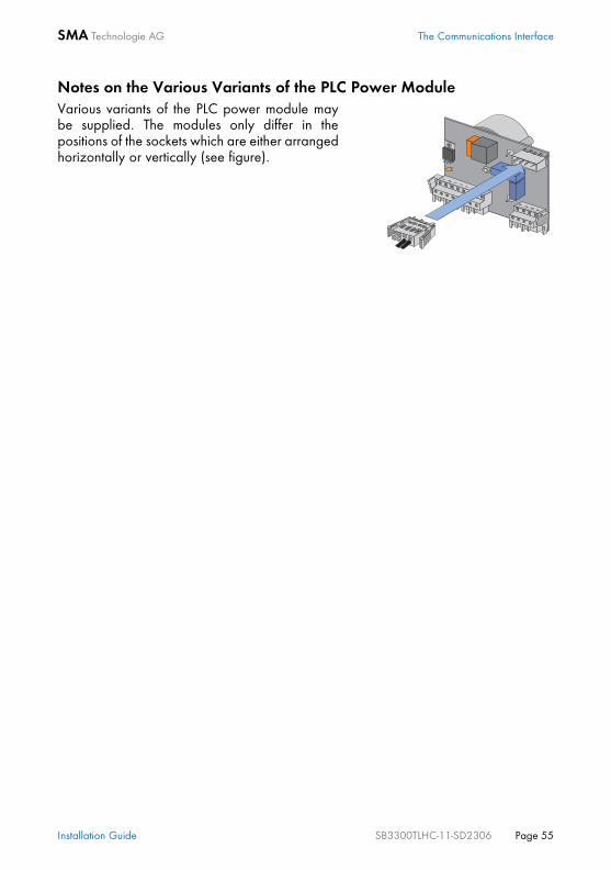
Notes on the Various Variants of the PLC Power ModuleVarious variants of the PLC power module maybe supplied. The modules only differ in thepositions of the sockets which are either arrangedhorizontally or vertically (see figure).
Installation Guide SB3300TLHC-11-SD2306 Page 55

The Communications Interface SMA Technologie AG
Page 56 SB3300TLHC-11-SD2306 Installation Guide
SMA Technologie AG Contact
12 ContactIf you have any questions or technical problems concerning the Sunny Boy SB 3300TLHC, contact our hotline. Have the following information available when you contactSMA: • Inverter type• Type and number of modules connected• Communication• Serial number of the Sunny Boy• Blink code or display of the Sunny Boy
Address: SMA Technologie AGHannoversche Straße 1 - 534266 NiestetalGermanyTel.:+49 (561) 95 22 - 499 Fax:+49 (561) 95 22 - [email protected]
Installation Guide SB3300TLHC-11-SD2306 Page 57

Legal Restrictions SMA Technologie AG
The information contained in this document is the property of SMA Technologie AG. Publishing its content,either partially or in full, requires the written permision of SMA Technologie AG. Any internal company copyingof the document for the purposes of evaluating the product or its correct implementation is allowed and doesnot require permission.
Exclusion of liabilityThe general terms and conditions of delivery of SMA Technologie AG shall apply.The content of these documents is continually checked and amended, where necessary. However,discrepancies cannot be excluded. No guarantee is made for the completeness of these documents. The latestversion is available on the Internet at www.SMA.de or from the usual sales channels.Guarantee or liability claims for damages of any kind are exlcuded if they are caused by one or more of thefollowing:• Improper or inappropriate use of the product• Operating the product in an unintended environment• Operating the product whilst ignoring relevant, statutory safety regulations in the deployment location• Ignoring safety warnings and instructions contained in all documents relevant to the product• Operating the product under incorrect safety or protection conditions• Altering the product or supplied software without authority• The product malfunctions due to operating attached or neighboring devices beyond statutory limit values• In case of unforeseen calamity or force majeure
Software licensingThe use of supplied software produced by SMA Technologie AG is subject to the following conditions:This software may be copied for internal company purposes and may be installed on any number ofcomputers. Supplied source codes may be changed or adapted for internal company purposes on your ownresponsibility. Drivers may also be transferred to other operating systems. Source codes may only be publishedwith the written permission of SMA Technologie AG. Sub-licensing of software is not permissible.Limitation of liability: SMA Technologie AG rejects any liability for direct or indirect damages arising from theuse of software developed by SMA Technologie AG. This also applies to the provision or non-provision ofsupport activities.Supplied software not developed by SMA Technologie AG is subject to the respective licensing and liabilityagreements of the manufacturer.
TrademarksAll trademarks are recognized even if these are not marked separately. Missing designations do not mean thata product or brand is not a registered trademark. SMA Technologie AGHannoversche Straße 1-534266 NiestetalGermanyTel. +49 561 9522-0Fax +49 561 9522-100www.SMA.deE-mail: [email protected]© 2005 SMA Technologie AG. All rights reserved.
Page 58 SB3300TLHC-11:SE2306 Installation Guide


www.SMA.deSales Solar Technology
SMA Technologie AGHannoversche Strasse 1–534266 Niestetal, GermanyTel. : +49 561 9522 4000Fax: +49 561 9522 4040E-Mail: [email protected]: +800 SUNNYBOYFreecall: +800 78669269
Innovation in Systems Technology
for the Success of Photovoltaics