Embed Size (px)
Citation preview

Lead free SOLUTIONS you can TRUST
®
CHALLENGING NEW TECHNOLOGIES
www.ko-ki.co.jp
This Product Information contains product performance assessed strictly according to our own test procedures and may not be compatible with results at end-users.
#46019E-1 Revised on MAR 19, 2010
Lead free SOLUTIONS you can TRUST
®
CHALLENGING NEW TECHNOLOGIES
Koki no-clean LEAD FREELEAD FREE solder paste
Super Super LowLow--VoidVoid & Anti& Anti--pillowpillowS3X58S3X58--MM500500Product information
Contents
Features
Specifications
Continual printability
Viscosity variation
Intermittent printability
Tack time
Heat slump
Solder balling
Super fine pattern wetting
Anti-Pillow defect
Solder spreading
Voltage applied SIR
Handling guide
Voiding
Solder beading
Halide content
Pillow defect

Lead free SOLUTIONS you can TRUST
®
CHALLENGING NEW TECHNOLOGIES
2Lead free SOLUTIONS you can TRUST
®
CHALLENGING NEW TECHNOLOGIES
Product FeaturesProduct Features
EEnsures nsures OUTSTANDING OUTSTANDING continual continual PRINTABILITYPRINTABILITY with super fine with super fine pitch (0.4mm/16mil) and CSP (>0.25mm dia.) applications pitch (0.4mm/16mil) and CSP (>0.25mm dia.) applications for normal to for normal to fast printing (10 ~ fast printing (10 ~ 8080mm/sec.) mm/sec.) and long stencil idle time.and long stencil idle time.
Highly heatHighly heat RESISTANT and PERFECT MELTINGRESISTANT and PERFECT MELTING and wetting at and wetting at super fine pitch (<0.4mm pitch) and micro components (<0.super fine pitch (<0.4mm pitch) and micro components (<0.2525mm mm diadiaCSP, 0603 chip). CSP, 0603 chip).
Conforms to HalogenConforms to Halogen--free free standard standard ((ClCl ++ BrBr:: belowbelow1500ppm1500ppm) ) ENEN--1458214582
Specially formulated flux chemistry ensures Specially formulated flux chemistry ensures EXTREMELYEXTREMELY LOW LOW VOIDINGVOIDING with with CSPsCSPs and broad contact area components, e.g. QFN.and broad contact area components, e.g. QFN.
Designed to prevent occurrence of Designed to prevent occurrence of HIDDEN PILLOW DEFECTSHIDDEN PILLOW DEFECTS..
EnablesEnables REUSEREUSE of leftover from previous day. of leftover from previous day. EconomicalEconomical..
S3X58S3X58--MM500500Contents
Features
Specifications
Continual printability
Viscosity variation
Intermittent printability
Tack time
Heat slump
Solder balling
Super fine pattern wetting
Anti-Pillow defect
Solder spreading
Voltage applied SIR
Handling guide
Voiding
Solder beading
Halide content

Lead free SOLUTIONS you can TRUST
®
CHALLENGING NEW TECHNOLOGIES
SpecificationsSpecifications
3
CHALLENGING NEW TECHNOLOGIES
Lead free SOLUTIONS you can TRUST
®
Application Printing – Stencil
Product S3X58-M500
Composit ion (%) Sn96.5Ag3.0Cu0.5
Melting point (°C) 217 - 219
Shape Spherical Allo
y
Particle s ize (μm) 20 – 38
Halide content (%) 0
Flux
Flux type*2 ROL0
Flux content (%) 11.5 ± 0.5
Viscosity*1 (Pa.S) 220 ± 30
Copper plate corrosion*3 Passed
Tack time > 48 hours
Pro
duct
Shelf l ife (below 10°C) 6 months
Contents
Features
Specifications
Continual printability
Viscosity variation
Intermittent printability
Tack time
Heat slump
Solder balling
Super fine pattern wetting
Anti-Pillow defect
Solder spreading
Voltage applied SIR
Handling guide
Voiding
Solder beading
Halide content1. Viscosity : Malcom spiral type viscometer,PCU-205 at 25ºC 10rpm 2. Flux type : According to IPC J-STD-004A3. Copper plate corrosion : In accordance with IPC J-STD-004A
S3X58S3X58--MM500500

Lead free SOLUTIONS you can TRUST
®
CHALLENGING NEW TECHNOLOGIES
Specifications Specifications –– Alloy selectionsAlloy selections
4
CHALLENGING NEW TECHNOLOGIES
Lead free SOLUTIONS you can TRUST
®
S3X - 58 - M 500Alloy composition
Particle size
Flux type
Flux number
Alloy composition (%)
M : Low halide, halide free
Flux number Solids and solvent used
S3X : Sn96.5 Ag3.0 Cu0.5
Flux type
m)( µParticle size
Contents
Features
Specifications
Continual printability
Viscosity variation
Intermittent printability
Tack time
Heat slump
Solder balling
Super fine pattern wetting
Anti-Pillow defect
Solder spreading
Voltage applied SIR
Handling guide
Voiding
Solder beading
Halide content
MM500500 SeriesSeries
58 : 20 ~ 38

Lead free SOLUTIONS you can TRUST
®
CHALLENGING NEW TECHNOLOGIES
Parallel to squeegee
0.25mm diameter
1st print 10th print10th print
after 200 strokes
Print parameters Test patterns Stencil : 0.12mm thickness, laser cut stencil 1. QFP pad pattern : Width 0.20 mm Printer : Model Yamaha YVP-Xg Length 1.5 mm Distance 0.2 mm Squeegee : Metal blade, Angle - 60° 2. MBGA pad pattern : Diameter 0.25mm Print speed : 40 mm/sec Stencil separation
speed : 10.0 mm/sec Atmosphere : 25±1°C (50±10%RH)
Continual printability S3X58Continual printability S3X58--M500M500
6
Newly developed additives provide a lubricating effect that greatly improve the paste release properties and assures excellent print quality with microBGA at high speed priting.
CHALLENGING NEW TECHNOLOGIES
Lead free SOLUTIONS you can TRUST
®
Contents
Features
Specifications
Continual printability
Viscosity variation
Intermittent printability
Tack time
Heat slump
Solder balling
Super fine pattern wetting
Anti-Pillow defect
Solder spreading
Voltage applied SIR
Handling guide
Voiding
Solder beading
Halide content
S3X58S3X58--MM500500

Lead free SOLUTIONS you can TRUST
®
CHALLENGING NEW TECHNOLOGIES
Viscosity variation in continual printingViscosity variation in continual printing• Print (knead) solder paste on the sealed-up stencil continually up 2880 strokes and observe viscosity variation. • Squeegee : Metal blades• Squeegee angle : 60• Squeegee speed : 30mm/sec.• Print stroke : 300mm• Printing environment : 23.0~25.0C, 50~60%RH
7
A newly developed flux formula has succeeded to realize consistent long term printabi lity by preventing excess viscosity drop due to shear thinning and excess increase due to chemical reaction between solder powder and flux during print rolling
*120 strokes/hour
CHALLENGING NEW TECHNOLOGIES
Lead free SOLUTIONS you can TRUST
®
0
50
100
150
200
250
300
0 500 1000 1500 2000 2500 3000
No. of print strokes (times)
Visc
osity
(Pa.
S)
S3X58-M500
Contents
Features
Specifications
Continual printability
Viscosity variation
Intermittent printability
Tack time
Heat slump
Solder balling
Super fine pattern wetting
Anti-Pillow defect
Solder spreading
Voltage applied SIR
Handling guide
Voiding
Solder beading
Halide content
S3X58S3X58--MM500500
®
CHALLENGING NEW TECHNOLOGIES
®
CHALLENGING NEW TECHNOLOGIES
Lead free SOLUTIONS you can TRUST
®
CHALLENGING NEW TECHNOLOGIES
1st print
1st print
after
60 min
8
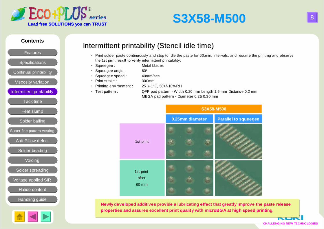
Newly developed additives provide a lubricating effect that greatly improve the paste release properties and assures excellent print quality with microBGA at high speed printing.
Lead free SOLUTIONS you can TRUST
®
Intermittent printability (Stencil idle time)Intermittent printability (Stencil idle time)Contents
Features
Specifications
Continual printability
Viscosity variation
Intermittent printability
Tack time
Heat slump
Solder balling
Super fine pattern wetting
Anti-Pillow defect
Solder spreading
Voltage applied SIR
Handling guide
Voiding
Solder beading
Halide content
• Print solder paste continuously and stop to idle the paste for 60,min. intervals, and resume the printing and observe the 1st print result to verify intermittent printability.
• Squeegee : Metal blades• Squeegee angle : 60• Squeegee speed : 40mm/sec.• Print stroke : 300mm• Printing environment : 25+/-1C, 50+/-10%RH• Test pattern : QFP pad pattern - Width 0.20 mm Length 1.5 mm Distance 0.2 mm
MBGA pad pattern - Diameter 0.25 0.30 mm
S3X58S3X58--MM500500
Parallel to squeegee0.25mm diameter
S3X58-M500

Lead free SOLUTIONS you can TRUST
®
CHALLENGING NEW TECHNOLOGIES
0
50
100
150
200
0 12 24 36 48
Time(hr)
Tac
kiness
(gf)
Tack timeTack time• Stencil : 0.2mm thick, 0.6mm dia. aperture • Measurement instrument : Malcom tackimeter TK-1• Probe pressure : 50gf• Pressurizing time : 0.2sec• Pull speed : 10mm/sec. • Test method : In accordance with JIS Z 3284• Test environment : 25+/-1C, 50+/-10%RH
Pull up at 100mm/sec.
Load 50gf
0.2 sec.
Tensile strength = Tack force
9
Unique solvent system successfully assures sufficient tack time.
CHALLENGING NEW TECHNOLOGIES
Lead free SOLUTIONS you can TRUST
®
Contents
Features
Specifications
Continual printability
Viscosity variation
Intermittent printability
Tack time
Heat slump
Solder balling
Super fine pattern wetting
Anti-Pillow defect
Solder spreading
Voltage applied SIR
Handling guide
Voiding
Solder beading
Halide content
S3X58S3X58--MM500500

Lead free SOLUTIONS you can TRUST
®
CHALLENGING NEW TECHNOLOGIES
Heat slumpHeat slump
• Stencil thickness : 0.2mm • Stencil aperture : Pattern (1) 3.0mm × 0.7mmm
Pattern (2) 3.0mm × 1.5mm • Spacing between apertures: 0.2mm to 1.2mm• Heat profile : 180ºC × 5min.
10
CHALLENGING NEW TECHNOLOGIES
Lead free SOLUTIONS you can TRUST
®
Improved heat slump property assures reduced soldering defects, such as solder beading and bridging.
No merge at 0.3mm No merge at 0.2mm
Pattern (1) Pattern (2)
0.2 0.3 0.4 0.5 mm
0.7 mm
3.0 mm
0.2 0.3 0.4 mm
3.0 mm
1.5 mm
Contents
Features
Specifications
Continual printability
Viscosity variation
Intermittent printability
Tack time
Heat slump
Solder balling
Super fine pattern wetting
Anti-Pillow defect
Solder spreading
Voltage applied SIR
Handling guide
Voiding
Solder beading
Halide content
S3X58S3X58--MM500500

Lead free SOLUTIONS you can TRUST
®
CHALLENGING NEW TECHNOLOGIES
Solder ballingSolder balling (Residue cosmetics)
432Category 1
11
• Stencil : 0.2mm thick• Stencil aperture : 6.5mm diameter• Solder pot temperature : 250ºC • Test method : In accordance with JIS Z 3284
CHALLENGING NEW TECHNOLOGIES
Lead free SOLUTIONS you can TRUST
®
1 hour after printing 24 hour after printing
Category 2~3Category 2~3
Contents
Features
Specifications
Continual printability
Viscosity variation
Intermittent printability
Tack time
Heat slump
Solder balling
Super fine pattern wetting
Anti-Pillow defect
Solder spreading
Voltage applied SIR
Handling guide
Voiding
Solder beading
Halide content
S3X58S3X58--MM500500

Lead free SOLUTIONS you can TRUST
®
CHALLENGING NEW TECHNOLOGIES
12Lead free SOLUTIONS you can TRUST
®
• Material : Glass epoxy FR-4• Surface treatment : OSP• Stencil thickness : 0.12mm (laser cut )• Pad size : 0.30mm diameter• Component: 0603 chip, • Stencil aperture : 100% aperture opening to pad• Heat source : Hot air convection• Zone structure : 5 pre-heat zones +2 peak zones• Atmosphere : Air• Reflow profile : See below
Larger relative surface areas of solder paste exposed due to miniaturization of components (CSP, 0603 chips), often cause incomplete melting due to excess oxidation during the reflow. An improved flux formula ensures complete coalescence by minimum deterioration of barrier performances .
0.30mm diameter
CHALLENGING NEW TECHNOLOGIES
Super fine pattern wettingSuper fine pattern wetting
0603 chip
Contents
Features
Specifications
Continual printability
Viscosity variation
Intermittent printability
Tack time
Heat slump
Solder balling
Super fine pattern wetting
Anti-Pillow defect
Solder spreading
Voltage applied SIR
Handling guide
Voiding
Solder beading
0
50
100
150
200
250
0 100 200 300 400
time(sec)
tem
p.(º
C)
0.30mm diameter 0603 chip pattern
Initial
After 4hour kneading
Halide content
S3X58S3X58--MM500500

Lead free SOLUTIONS you can TRUST
®
CHALLENGING NEW TECHNOLOGIES
13Lead free SOLUTIONS you can TRUST
®
• Material : Glass epoxy FR-4• Surface treatment : OSP• Stencil thickness : 0.12mm (laser cut )• Pad size : 0.8×0.8mm diameter• Component: 0.76mm ball SAC305• Stencil aperture : 100% aperture opening to pad• Heat source : Solder pod 275℃
• mount interval 20sec
S3X58-M500 indicated much longer heat durability nearly up to 80sec., while the conventional solder paste lost activation less than 40 sec. since the solder paste started melting.
CHALLENGING NEW TECHNOLOGIES
AntiAnti--Pillow testPillow testgood
NG
Drop solder ball every 20 sec. after the solder paste has melted to see heat durability of flux.
Contents
Features
Specifications
Continual printability
Viscosity variation
Intermittent printability
Tack time
Heat slump
Solder balling
Super fine pattern wetting
Anti-Pillow defect
Voltage applied SIR
Handling guide
Copper corrosion
Voiding
Solder beading
20sec 40secsec
S3X58-M500
Conventional paste
(ROL0)
60sec 80secPillow defect
S3X58S3X58--MM500500

Lead free SOLUTIONS you can TRUST
®
CHALLENGING NEW TECHNOLOGIES
14Lead free SOLUTIONS you can TRUST
®
Contents
• Material : Glass epoxy FR-4• Surface treatment : OSP• Stencil thickness : 0.12mm (laser cut )• Stencil aperture : 100% aperture opening to pad• Components
2125 resistor : 30 pcs./board1608 resistor: 30 pcs./boardTotal : 60 chips/board
• Heat source : Hot air convection• Zone structure : 5 pre-heat zones +2 peak zones• Atmosphere : Air
*Fault finding design
1608 R
2125R
20 0 143
0
20
40
60
Init ial Af ter 2-hourkneading on stencil
Af ter 4-hourkneading on stencil
No.
of
sold
er b
eadi
ng (
pc.)
2125R 1608R
Features
Specifications
Continual printability
Viscosity variation
Intermittent printability
Tack time
Heat slump
Solder balling
Super fine pattern wetting
Anti-Pillow defect
Solder spreading
Voltage applied SIR
Handling guide
Voiding
Solder beading
Halide content
Solder beadingSolder beading
S3X58S3X58--MM500500

Lead free SOLUTIONS you can TRUST
®
CHALLENGING NEW TECHNOLOGIES
VoidingVoiding• Material : Glass epoxy FR-4• Surface treatment : OSP• Stencil thickness : 0.12mm (laser cut )• Stencil aperture : 100% aperture opening to pad• Components
PwTr, QFN, 2125R, 100% Sn plated1.0mm pitch BGA: SAC305
• Heat source : Hot air convection• Zone structure : 5 pre-heat zones +2 peak zones• Atmosphere : Air• Reflow profile : Same as “Super fine pattern wetting”
15Lead free SOLUTIONS you can TRUST
®
1.0mm pitch BGA
PwTr
QFN
2125R
Contents
Features
Specifications
Continual printability
Viscosity variation
Intermittent printability
Tack time
Heat slump
Solder balling
Super fine pattern wetting
Anti-Pillow defect
Solder spreading
Voltage applied SIR
Handling guide
Voiding
Solder beading
Initial
After 4-hour kneading on
stencil
PwTr 2125)QFN BGA
Conventional product
Halide content
S3X58S3X58--MM500500

Lead free SOLUTIONS you can TRUST
®
CHALLENGING NEW TECHNOLOGIES
16Lead free SOLUTIONS you can TRUST
®
Solder spreadingSolder spreading
Material pieces : Copper, Brass, Nickel (*Pre-conditioning – acetone cleaning + soft etched by 15% sulfuric acid solution)
• Stencil thickness : 0.2mm (laser cut)• Stencil aperture : 6.5mm diameter• Heat source & temp.: Reflow simulator *Same profile as “Super fine pattern wetting”.
* DefinitionCategory 1 : Solder has spread more than the area where solder paste was printed.Category 2 : Solder has spread whole area where solder pasted was printed.Category 3 : Solder has not partially spread. Category 4 : Solder spread is less than the area where solder paste was printed.
Bra ss Copper plate Nickel
Category 2 Category 2 Category 3
Contents
Features
Specifications
Continual printability
Viscosity variation
Intermittent printability
Tack time
Heat slump
Solder balling
Super fine pattern wetting
Anti-Pillow defect
Solder spreading
Voltage applied SIR
Handling guide
Voiding
Solder beading
Halide content
S3X58S3X58--MM500500

Lead free SOLUTIONS you can TRUST
®
CHALLENGING NEW TECHNOLOGIES
Voltage applied surface insulation resistance Voltage applied surface insulation resistance • Test conditions : 85±2ºC × 85%RH for 1000 hours• Stencil thickness : 100 micron• Comb type electrode : JIS type-II• Measurement voltage : DC100V• Voltage applied : DC50V• Test method : JIS Z 3197
17
No evidence of electromigration can be observed.
CHALLENGING NEW TECHNOLOGIES
Lead free SOLUTIONS you can TRUST
®
Contents
SIR GRAPH
1.00E+07
1.00E+08
1.00E+09
1.00E+10
1.00E+11
1.00E+12
1.00E+13
1.00E+14
1.00E+15
1.00E+16
0 100 200 300 400 500 600 700 800 900 1000
Time (hour)
Insu
latio
n re
sist
ance
(Ω)
Features
Specifications
Continual printability
Viscosity variation
Intermittent printability
Tack time
Heat slump
Solder balling
Super fine pattern wetting
Anti-Pillow defect
Solder spreading
Voltage applied SIR
Handling guide
Voiding
Solder beading
Halide content
S3X58S3X58--MM500500

Lead free SOLUTIONS you can TRUST
®
CHALLENGING NEW TECHNOLOGIES
Features
Specifications
Continual printability
Viscosity variation
Intermittent printability
Tack time
Heat slump
Solder balling
Super fine pattern wetting
Anti-Pillow defect
Solder spreading
Voltage applied SIR
Handling guide
Voiding
Solder beading
Halide content
HalideHalide ccontentontent
・Test method : A: IPC-TM650 2.3.28.1B: BS EN14582
・ Measurement instrument: ICS-1500 (DIONEX)AQF-100 (MITSUBISHI CHEMICAL ANALYTECH)
NDNDChloride
0.030.02Bromide
NDNDFluoride
BAMethod
Halide content (wt%)
18
Contents
S3X58S3X58--MM500500

Lead free SOLUTIONS you can TRUST
®
CHALLENGING NEW TECHNOLOGIES
Handling guideHandling guide
19
1. Printing 1) Recommended printing parameters
(1) Squeegee1. Kind : Flat2. Material : Rubber or metal blade3. Angle : 60~70º (rubber) or metal blade4. Pressure : Lowest5. Squeegee speed : 20~80mm/sec.
(2) Stencil 1. Thickness : 150~100m for 0.65~0.4mm pitch pattern 2. Type : : Laser or electroform3. Separation speed : 7.0~10.0mm/sec. 4. Snap-off distance : 0mm
(3) Ambiance1. Temperature : 22~25ºC2. Humidity : 40~60%RH3. Air draft : Air draft in the printer badly affects stencil life and tack performance of
solder pastes.2. Shelf life
0~10ºC : 6 months from manufacturing date
* Manufacturing date can be obtained from the lot number
ex. Lot No. 9 06 15 2No. of lot : 2nd Date : 15stMonth : JulyYear : 2008
CHALLENGING NEW TECHNOLOGIES
Lead free SOLUTIONS you can TRUST
®
Contents
Features
Specifications
Continual printability
Viscosity variation
Intermittent printability
Tack time
Heat slump
Solder balling
Super fine pattern wetting
Anti-Pillow defect
Solder spreading
Voltage applied SIR
Handling guide
Voiding
Solder beading
Halide content
S3X58S3X58--MM500500

Lead free SOLUTIONS you can TRUST
®
CHALLENGING NEW TECHNOLOGIES
20Lead free SOLUTIONS you can TRUST
®
Handling guideHandling guide - Recommended reflow profile
Excess pre-heating (time & temperature) may cause too much oxidation.
Relatively short and low pre-heat may be recommendable, especially for fine pitch/micro pattern components .
200
250
100
150
Pre-heat temp.110~190ºC 60~120sec.
Peak temp.230~250ºC
(ºC)
Ramp-up temp.1.0~3.0ºC/sec.
180 240(sec.)
Over 220ºC > 45 sec.
30090
50
60
CHALLENGING NEW TECHNOLOGIES
Contents
Features
Specifications
Continual printability
Viscosity variation
Intermittent printability
Tack time
Heat slump
Solder balling
Super fine pattern wetting
Anti-Pillow defect
Solder spreading
Voltage applied SIR
Handling guide
Voiding
Solder bead
Halide content
For reduction of voids, it is recommended to have >50sec. as time above liquidus and >240ºC of peak temperatures.
S3X58S3X58--MM500500