Embed Size (px)
Citation preview

SUPERALLOY POWDIER PROCESSING, PROPERTIES AND TURBINE DISK APPLICATIONS
D.R. Chang, D.D. Krueger, R.A. Sprague
General Electric Company Aircraft Engine Business Group
Cincinnati, Ohio 45215 USA
Abstract
This paper discusses the characteristics of inclusions resulting from various consolidation techniques and their effects on the fatigue properties of a ,typical high-strength PM superalloy, Rene' 95. The nature, origin, 'and size range of defects found in HIP, HIP t isothermally forged, extruded t isothermally forged material are described and th'eir influence on LCF behavior analyzed. Thermomechanical processing improves the LCF life considerably. The improvement is attributed to the dispersion of large defects. The LCF life of forged material is also benefited by a greater tendency toward internal fatigue initiation at crystallographic origins or initiated at smaller defects. The effects of heat treatment on the mechanical properties and microstructural features of extruded t isothermally forged materials are also investigated.
245

Introduction
The demand for improved jet engine efficiency and performance has resulted in the continued development of high strength disk superalloys, such as Rene' 95. Concurrent with the increase in strength is a significant decrease in conventional hot workability. The decrease in workability adversely affects the overall component cost and the ability to achieve desirable properties. This has spurred the development of powder metallurgy (PM) techniques for producing components of highly alloyed compositions to achieve the desired microstructures, properties, and cost effectivity.
While PM processing provides property and cost advantages over cast and wrought processing, the low cycle fatigue (LCF) capability of PM materials has been limited by the presence of inclusions. These inclusions or defects are introduced during various processing steps. Their nature, size, and distribution are dependent on the PM consolidation technique. PM superalloys can be consolidated by hot isostatic pressing (HIP), HIP followed by isothermal forging (HtF), extrusion (EX), EX followed by isothermal forging (EX t F) or other combinations of compaction and working. A thorough knowledge of the effect of consolidation on defect characteristics is essential for process improvement, material behavior understanding, and hardware performance prediction.
This paper describes the defects which have been induced or are naturally occuring in PM Rene' 95 consolidated by various techniques. An emphasis is placed on the analyses of defect morphologies and their relationship to LCF behavior. For purposes of this paper, a defect is defined as any material heterogeneitywhich results in a failure mode at the origin by any mechanism other than crystallographic initiation, In addition, the microstructure and mechanical properties resulting from various consolidation techniques and heat treatments are discussed.
Materials and Processing
PM Rene' 95 has a nominal composition (in weight X) of O.O65C, 13Cr, 8C0, 3.5A1, 2.5Ti, 3.5Cb, 3.5M0, 3.5W, and balance Ni. It normally consists of primary, intermediate, and fine gamma prime (y '1 in a highly alloyed gamma matrix which also contains a fine dispersion of Cb, Ti-rich carbides. The materials discussed in this paper were produced from -150 mesh argon atomized powder. The consolidation techniques considered include HIP, HtF, EX, and EXtF.
The HIP material was consolidated with a 205O"F/15 KS1 HIP cycle. The heat treatment consisted of a 2065"F/l Hr., oil quench solution, followed by a 16OO"F/l Hr. plus 12OO"F/24 Hrs. air cool age cycle. The typical microstructure, shown in Figure la, has an average grain size of ASTM 8 to 10. (TEM) has been used to study the Y
Transmission Electron M-7 oscopy u ' and dislocation features . The primary Y ', located
at grain boundaries, is generally on the order of 1 micron in diameter. Intermediate and fine y I, located in the grain interiors, typically measure 0.5 and 0.1 microns in size respectively. Both of these Y I particles have a roughly spherical morphology while the primary y ' have a blocky shape. An array of misfit dislocations usually surrounds the intermediate y I. Some dislocations also exist in matrix regions
246

Figure 1 - Optical micrographs showing typical fine
9 rain microstructures of
HIP (A), H+F B), and EX+F (C) P/M Rene' 95.
247

between the intermediate y I. These are generally found in a random array although distinct slip bands, in rare instances, have also been observed. There is no indication of interaction between the matrix dislocations and fine y I. Figure 2a shows a TEM thin foil micrograph which illustrates the dislocation distribution near and between intermediate y ' particles.
The H+F material was produced by isothermal forging of HIP preforms at temperatures between 2000°F and 2050°F. The forging height reduction was nominally 70 to 80%. This material was solutioned at 2050°F for 1 hour, air cooled and aged at 1400°F for 8 to 16 hours. H+F Rene' 95 has a uniform recrystallized grain structure with an average grain size of ASTM 10 to 11. The typical microstructure is shown in Figure lb. The EXtF material was isothermally forged and heat treated similarly to the H+F material. The preform in this process was consolidated by hot extrusion with a nominal 6.5 to 1 reduction in cross section area. The microstructure of EXtF materials, shown in Figure lc, is similar to that of HtF material. T e y also been studied(l !
I and dislocation features of EXtF Rene' 95 have . Relative to HIP Rene' 95, this material showed
somewhat larger (l-2 microns in diameter) and more frequent primary y 0 smaller intermediate y ' (0.2-0.3 microns in diameter) and fine y I having a similar size. The fine y ' also exhibited a spherical morphology while the intermediate y ' was cuboidal rather than spherical. Some differences in the dislocation network were also observed. No misfit dislocations surrounded the intermediate Y ', and the matrix dislocations showed a very heterogeneous distribution between grains. In grains of high dislocation density, the matrix dislocations were localized between the intermediate Y I particles and showed a tendency to form bands along crystallographic directions. Occasional sub-grain boundaries were also observed. Figure 2b shows a TEM micrograph which illustrates the cuboidal morphology of the intermediate y ', lack of misfit dislocations near these particles, and the banding of matrix dislocations typically observed.
Defect Characterization and Effect on Low Cycle Fatigue
HIP PM Rene' 95 Defects
PM defects have been extensively studied for HIP consolidated Rene'
4~,ci’,~~‘,~:FE’,1”~~~g~~~(~~~~~. ly resulted from a large scale study of LCF
Table 1 summarizes the characteristics of four types of defects found at the failure initiation sites of HIP Rene' 95 LCF specimens.
Type 1 and 2 defects are illustrated in Figure 3. These defects are ceramic inclusions. Type 1 exist as discrete and often chunky particles while Type 2 are agglomerates of fine particles. Both types originate from the melting crucible, pouring tundish or the atomizing nozzle. Aluminum is usually the major metallic element with Zr, Mg or Ca also present in various amounts. type of ceramic involved.
The amount of minor elements depends on the The sizes of Type 1 and Type 2 defects are
limited by the screen opening through which the powders have been sieved and are not altered significantly by reaction during the HIP cycle. As indicated in Table I, the ceramic defects average about 10 mils2 with very few reaching 50-100 mils2.
248
A) HIP PM Rene' 95
B) EX+F PM Rene' 95
Figure 2 - TEM micrographs of PM Rene' 95.
249

Figure 3 - Micrographs showing ceramic defects.
A) Type 1 SEM fractograph showing fatigue initiation site
B) Type 2 SEM fractograph showing fatigue initiation site
C) Type 2 Optical micrograph from metallographic section
250
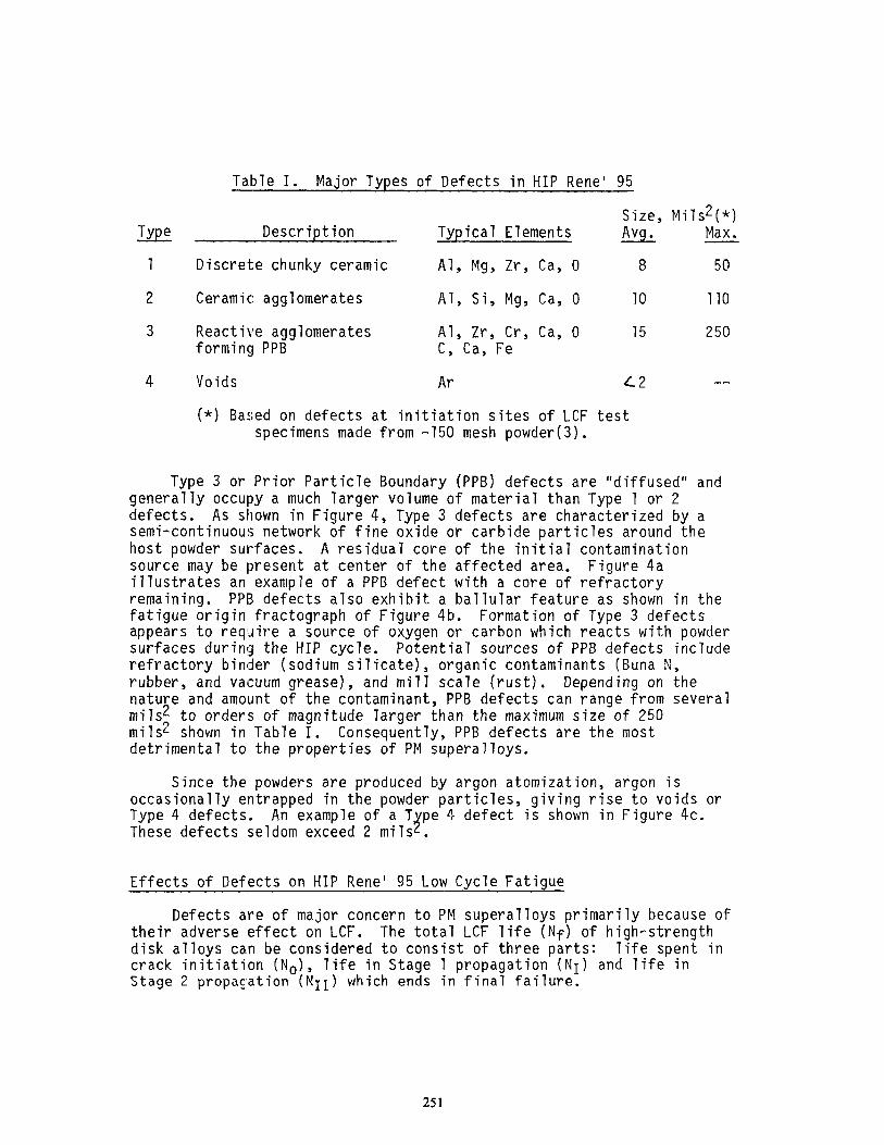
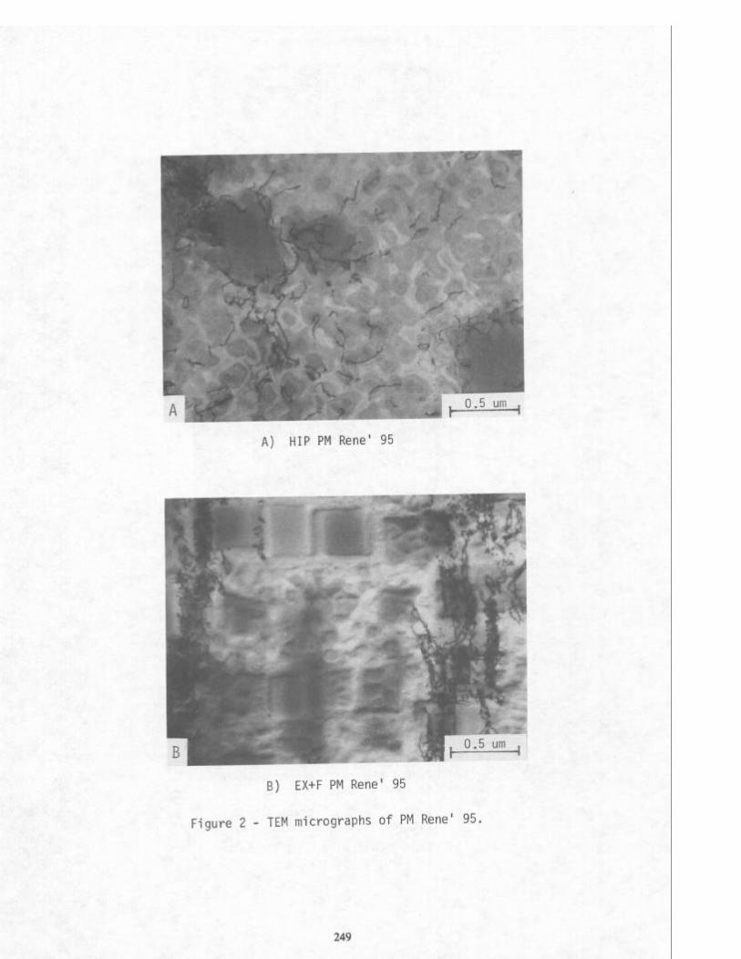
Table I. - Major Types of Defects in HIP Rene' 95
Size. Mils2(*) Description Typical Elements nvg.
Discrete chunky ceramic Al, Mg, Zr, Ca, 0 8
Ceramic agglomerates Al, Si, Mg, Ca, 0 10
Reactive agglomerates Al, Zr, Cr, Ca, 0 15 forming PPB C, Ca, Fe
Voids Ar c2
(*) Based on defects at initiation sites of LCF test specimens made from -150 mesh powder(3).
Max.
50
110
250
. .
Type 3 or Prior Particle Boundary (PPB) defects are "diffused" and generally occupy a much larger volume of material than Type 1 or 2 defects. As shown in Figure 4, Type 3 defects are characterized by a semi-continuous network of fine oxide or carbide particles around the host powder surfaces. A residual core of the initial contamination source may be present at center of the affected area. Figure 4a illustrates an example of a PPB defect with a core of refractory remaining. PPB defects also exhibit a ballular feature as shown in the fatigue origin fractograph of Figure 4b. Formation of Type 3 defects appears to require a source of oxygen or carbon which reacts with powder surfaces during the HIP cycle. Potential sources of PPB defects include refractory binder (sodium silicate), organic contaminants (Buna N, rubber, and vacuum grease), and mill scale (rust). Depending on the nature and amount of the contaminant, PPB defects can range from several mils* to orders of magnitude 'larger than the maximum size of 250 mils2 shown in Table I. Consequently, PPB defects are the most detrimental to the properties of PM superalloys.
Since the powders are produced by argon atomization, argon is occasionally entrapped in the powder particles, giving rise to voids or Type 4 defects. An example of a T pe 4 defect is shown in Figure 4c. These defects seldom exceed 2 mils J .
Effects of Defects on HIP Rene' 95 Low Cycle Fatigue
Defects are of major concern to PM superalloys primarily because of their adverse effect on LCF. The total LCF life (Nf) of high-strength disk alloys can be considered to consist of three parts: life spent in crack initiation (No), life in Stage 1 propagation (NI) and life in Stage 2 propagation (NII) which ends in final failure.
251
Figure 4 - Micrographs showing:
A) Type 3 (PPB) Optical micrograph from a metallographic section
B) Type 3 (PPB) SEM fractograph showing fatigue initiation site
C) Type 4 (void) SEM fractograph showing fatigue initiation site
252
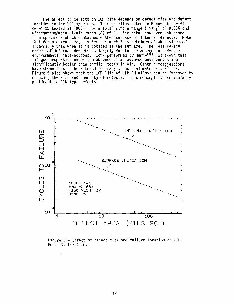
The effect iof defects on LCF life depends on defect size and defect location in the LCF specimen. This is illustrated in Figure 5 for HIP Rene' 95 tested at 1000°F for a total strain range ( Ac t) of 0.66% and alternating/mean strain ratio (A) of 1. The data shown were obtained from specimens which contained either surface or internal defects. Note that for a given size, a defect is much less detrimental when situated internally than when it is located at the surface. The less severe effect of internal defects is largely due to the abs n e of adverse environmental interactions. Work performed by Henry 4 has shown that PF fatigue properties under the absence of an adverse environment are significantly better than similar tests in air. Other inves * 'ons have shown this to be a trend for many structural materials t39?8 Figure 5 also shows that the LCF life of HIP PM alloys can be imprived by reducing the size and quantity of defects. This concept is particularly pertinent to PPB type defects.
10
IO
ul W
d > 0
10
5 5
I 1 I ,‘,I’, I 9 , a,,‘, I I I
\
-\
-1
-\ -1 INTERNAL INITIATION INTERNAL INITIATION
-1 4 -\,
-1 -\
-\ -1
-\‘,
4 SURFACE INITIATION 4
_ 3 I 1 10 100
lOOOF A-i na =0.66% -150 MESH HIP RENE 95
DEFECT AREA (MILS SQ.)
Figure 5 - Effect of defect size and failure location on HIP Rene' 951 LCF life.
253

Effect of Thermomechanical Processina on Defects
Doped Materials
Typical -150 mesh HIP Rene' 95 material consists of more than six billion original powder particles per pound. The frequency of large reactive defects (PPB) in HIP Rene' 95 was found at a very low level of one in every 1.5 trillion powder particles. This calculation was based on vast hardware inspection experience using extremely sensitive ultrasonic inspection techniques. In order to study the effect of thermomechanical processing (TMP) on defects and properties, Rene' 95 was purposely doped with contaminants to increase the frequency of observance,
Chang et. al(3) have shown that when doped HIP Rene' 95 was isothermally forged, the large reactive type (PPB) defects were dispersed and reduced, while little effect was observed on Type 1 chunky ceramic inclusions. The dopants selected were Al203 (Type 1, -60 t80 mesh, 1000 particles per pound), Buna N (0 ring material, Type 3, 500 particles per pound) and vacuum grease (Type 3, ICC per pound). The materials were HIP'd at 205OoF and isothermally forged at 2050°F to an 80% reduction. As can be seen in Figure 6 the larger PPB defects were greatly reduced in size and dispersed into stringer shapes. The dopants in HIP material reduced both tensile ductility and LCF life as shown in Table II. Consistent with the defect modification, TMP improved both tensile ductility and LCF life.
Table II. Effect of Isothermal Forging on Ductility and LCt Life of Seeded Rene' 95 (Ref. 3)
RT/lZOOF
Tensile
Material % Elong.
1. HIP (Unseeded) 17/15
2. HtF (Unseeded) 20/22
3. HIP (A1203 Seeded) 10/5
4. (3) + F 14/15
5. HIP (Buna N Seeded) 10/3
6. (5) + F 19/19
1000~/0.66% A et
LCF Life, Cycles
Average
36,840
128,848
3,411
8,219
2,561
134,001
* All -150 mesh powder. Forging reduction: 80%
A similar study was conducted to investigate the effect of extrusion and extrusion plus isothermal forging on defects. Since the primary concern was for large reactive defects, two PPB forming dopants were selected; Buna N,(an organic carbide type former) and mill scale (an inorganic oxide type former). These two dopants were separately introduced into Rene' 95 powder which was then processed to produce HIP, EX, and EXtF materials. The extrusion was processed with a nominal 6.5 to 1 area reduction ratio. Isothermal forging resulted in a 60%
254

Figure 6 - Optical micrographs showing effect of isothermal forging on defects and LCF failure initiation in H+F Rene' 95: A) Alumina inclusion in H+F B) Vacuum grease induced PPB in HIP C) PPB modification by 80% forging
reduction
255
reduction in height. as large as 1200 mi12.
The HIP material showed many PPB defects with some It is evident from Figure 7 that both EX and
EXtF greatly reduced and dispersed the reactive defects. In addition, Figure 8 shows that TMP has destroyed the ballular nature of PPB defects and generated a recrystallized zone around the core.
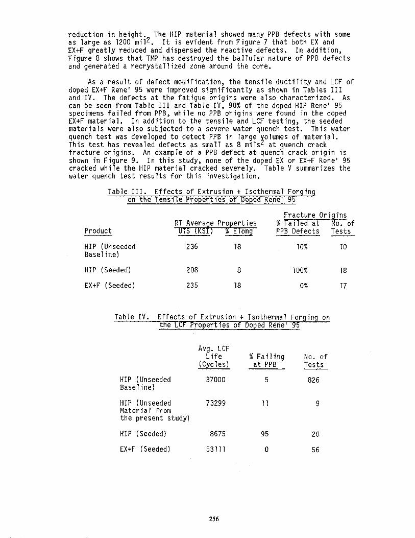
As a result of defect modification, the tensile ductility and LCF of doped EXtF Rene' 95 were improved significantly as shown in Tables III and IV. The defects at the fatigue origins were also characterized. As can be seen from Table III and Table IV, 90% of the doped HIP Rene’ 95 specimens failed from PPB, while no PPB origins were found in the doped EXtF material. In addition to the tensile and LCF testing, the seeded materials were also subjected to a severe water quench test. This water quench test was developed to detect PPB in large olumes of material. This test has revealed defects as small as 8 mils 3 at quench crack fracture origins. An example of a PPB defect at quench crack origin is shown in Figure 9. In this study, none of the doped EX or EXtF Rene' 95 cracked while the HIP material cracked severely. Table V summarizes the water quench test results for this investigation.
Table III. Effects of Extrusion t Isothermal Forging on the Tensile Properties of Doped Rene' 95
Product
Fracture Origins RT Average Properties % Failed at No. of UTS (KSI) % PPB Defects Tests
HIP (Unseeded Baseline)
HIP (Seeded)
EXtF (Seeded)
236 18 10% 10
208 8 100% 18
235 18 0% 17
Table IV. Effects of Extrusion t Isothermal Forging on the LCF Properties of Doped Rene' 95
HIP (Unseeded Baseline)
HIP (Unseeded Material from the present study)
HIP (Seeded)
EXtF (Seeded)
Avg. LCF Life % Failing No. of
(Cycles) at PPB Tests
37000 5 826
73299 11 9
8675 95 20
53111 0 56
256

_ B ” 1 >, >-a d . .a* *, 7 T r’ -, ,.~
i - 0 de _. -; * *~ j”‘”
0” t ** -*,- I - ,a
I’ * ‘*. .=
0 I *” 8.” ;“* I .** . . - L’
--. * *‘. ‘ % , . /. _ 1 * -*,
_ e-1”. ;
_ * * ’ -*_ ; - v ‘- 1 “, > “. ‘-w *_
.’ r** b Iv . &‘~ d
s-.. 60 urn
Figure 7 - Optical micrographs showing typical microstructure of defects at LCF origins in doped Rene' 95 material.
A) HIP B) As-Extruded
C) EX+F
257

1
*
L -.* .1
- i L ‘* 1 “I i 1 * #FI ar:
p) * “.“. a** . _ 1-1 + * t-
-.+
Figure 8 - SEM fractographs of typical seeded defects observed at LCF origins in doped Rene' 95 material.
A) HIP
B) As-Extruded
C) EX+F
258

Figure 9 - Water quench test fracture micro- graph showing PPB in crack initiation site of doped HIP Rene' 95.
259

Table V. Results of Water Quench Tests for Doped Rene' 95
Material Type
Seed Type HIP As-Extruded EX+F
Buna N 3 major cracks; Did not crack Did not crack 400, 400, 704 mi12 PPB defects at crack origin
Mill Scale 5 major cracks; Did not crack Did not crack 304, 404, 572 624, 900 mi12 PPB defects at crack origins
Undoped Materials
Defect Type and Size. Table VI compares th defect type, size and failure locations of LCF specimens from HIP, H+F 3), if and EX+F PM Rene' 95. In contrast to HIP specimens which invariable failed from impurity-related defects (Types 1 through 4), a number of TMP specimens failed from Type 5 origins which are crystallographic and do not contain impurity-related defects. A typical Type 5 defect is shown in Figure 10. These origins also show the regions of crack initiation and Stage 1 propagation as evident by the small facets delineating the initiation site. Consequently, initiations from a Type 5 defect are usually associated with long LCF life.
Figure 10 - Type 5 Crystallographic Defect.
A) Optical micrograph from a metallographic section
B) SEM fractoqraph of fatigue initiation-site
260

Type 1 and Type 2 ceramic inclusions constituted the most frequently observed defects in all materials. The average size of each type (5-10 mils2) did not differ significantly between all three materials, although the maximum sizes (especially Type 2) appear to be somewhat smaller in the TMP specimens. This suggests that the Type 2 defects may have been dispersed by TMP.
The Type 3 [[PPB) defects were only infrequently found in the HIP material, much less in the HtF material with 60-80% forging reduction, and none were found in the EX+F material. In addition, the average and especially the m$ximum size of Type 3 defects found in the HtF specimens (4.2 and 4.5 mill-) were considerably smaller than those found in the HIP specimens (1!3 and 242 mi12). The frequency of failure from void defects (Type 4) was increased in the TMP specimens, 14430% for HtF and 8-26% for EX+F atAq< 0.75%,as compared with 1% or less for the HIP specimens. The lack of Type 4 failures in the latter case is not surprising since the relatively small voids would be bypassed as initiation sites in favor of the larger defects present. Once the larger defects had been dispersed by TMP, then the more abundant smaller defects would be favored for crack initiation.
Effect of Thermal Mechanical Processing on Low Cycle Fatigue
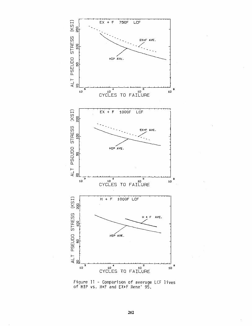
The LCF lives of HIP, HtF and EXtF materials are compared in Figure 11. The comparison shows that the lives of TMP materials are significantly better than those of HIP material. The LCF life improvement through TMP is related to the fatigue origin defect type and size as discussed below.
It was evident from the previous discussion and Table VI that TMP dispersed and reduced the size of defects. In addition, a larger percentage of TMP specimens failed from smaller Type 4 void defects (<2 mi12) and Type 5 crystallographic origins. The reduced defect size and the lack of reactive defects resulted in the improved LCF life. The TMP materials generally had a very fine grain size which also helped improve the LCF life by retarding the initiation process.
The TMP specimens were much less prone to surface initiation. At lOOO"F, 0.66% A@t, very few failures at surface defects were observed. Under conditions more conducive to surface initiation (75O"F/ Act >0.75%), the frequency of surface failure was 33% for HtF, 15% for EXtF andl 75% for HIP specimens.
Figure 12 compares the size of internal defects for EXtF material vs. HIP material as a function of LCF life. The internal defects observed (Type 1' and Type 2) are generally smaller for TMP material than HIP material. In addition, there is an improvement in LCF life for a given defect size. This suggests that the initiation and Stage 1 propagation periods for EXtF are longer than HIP material. A comparison was also made for surface initiated failure and the improvement was not as obvious.
261
I-
1:
EX + F lOOOF LCF
:
;
HIP AVE.
:: 1 3 4 5 10
CYCirlES TO FAIbE IO
H H+F IOOOF LCF
2 O- 1 -EJ
6
3 4 5 6 IO
CYC?ES TO FAItDURE 10
Figure 11 - Comparison of average LCF lives of HIP vs. H+F and EX+F Rene' 95.
262

Tabl
e V
I. C
ompa
rison
of
D
efec
t Ty
pe
and
Siz
e at
LC
F In
itiat
ion
Site
H
IP
vs.
Htl-
an
d E
XtF
NO
. O
F FR
EQ
UE
NC
Y O
F S
UR
FAC
E
DE
FEC
T TY
PE
D
EFE
CT
SIZ
E,
MIL
S2
TEM
P
FAIL
UR
ES
%
D
EFE
CT
HIP
H
tF
EX
+F
OF
kt%
M
ATE
RIA
L %
1
2 3
4 5
- -
- -
- -
- TY
PE
A
VE
. M
AX
. A
VE
. M
AX
. A
VE
. M
AX
. -
-
1000
0.
75
HIP
76
H+F
5
EX
tF
37
2174
410
1 6.
7 36
5.
3 76
.0
4.8
66
5 0
0 29
2
9.5
50
6.1
11.2
8.
9
75
25
0 0
0 3
18.7
24
2 N
one
Non
e N
one
4 6.
3 10
.3
Non
e N
one
Non
e
9.8
12.1
Non
e
Non
e
1000
0.
75
HIP
HtF
EX
tF
750
0.75
H
IP
HtF
EX
tF
31 5 4 75
33
15
15 7
7 7
1 0
7 11
.2
50
3.9
12.0
4.
8 8.
1
29
28
3 74
26
2 13
.1
111
4.8
13.0
7.
1 16
.0
38
54
0 8
0 3
19.3
83
.6
4.2
4.5
Non
e N
one
4 5.
3 6.
8 0.
8 1.
4 1.
0 1.
5
33
58
9 0
0 1
7.5
9.1
6.4
13.7
4.
1 8.
7
73 2
4 0
30
33
2 8.
6 13
.1
4.2
9.3
5.2
10.2
32
39
0 26
3
3 --
6.4
Non
e N
one
Non
e N
one
4 N
one
Non
e 1.
1 1.
5 0.
5 0.
7

IO
w
10
7
t I I111111, I ~(11111, I 11 1111), 11111
DEFECT SIZE VS LIFE - -150 MESH RENE 95 IOOOF 0.66% Et
INTERNAL INITIATION 8
DEFECT AREA (MILS SQ.) Figure 12 - Internal initiated defect size vs. LCF of HIP and EX+FRene' 95 tested at 1000°F 0.66% Et.
A similar 'm rovement Minor and Gayda 7 . 77
in LCF life for TMP materials was observed by They investigated the LCF behavior of HIP, EXtF
and cast plus wrought Rene' 95. Figure 13 shows the LCF comparison at 12OOoF. At high strain ranges the LCF lives of al7 three materials are similar, while at strain ranges less than 7.0% the EXtF shows the longest LCF life. Their study also confirmed that the EXtF material was more prone to internally initiated failure.
1.6
1.4
1.2
A&-t, %
.8 1 ) ni
I
.6,
ati?k .k?surface Failure i&
'd
.4, D & Test Stopped
t 1
107 lo2 lo3 104 105 106 Nf, Cycles
Figure 13 - Cyclic life - total strain range of Rene' 95 at 12OOOF.
264

Processi!ng, Microstructure and Mechanical Properties of Extruded plus Isothermally Forged PM Rene' 95 --
The first full-scale EXtF Rene' 95 gas turbine engine components were processed to the disk configuration shown schematically in Figure 74. This shape was obtained by isothermally forging a six inch diameter extrusion at 2000°F to a minimum height reduction of 70%. Figure 75 shows the typical fine recrystallized grain structure for three disk locations. The average grain size measured ASTM 71-12.
A preliminary investigation was conducted on sample disk material to study the effects of heat treatment on mechanical properties. The selected heat treatments were:
A) 2050°F/1 hr./salt quench t 16OO"F/l hr./air cool + 1200°F/24 hrs./air cool.
B) 2000°F/1 hr./oil quench t 7400°F/16 hrs./air Cool.
and C) 205O"F/l hr./air cool t 1400°F/76 hrs./air cool.
The "solution" temperature in each of these heat treatments is below the Y' solvus (approximately 2120°F). This prevented the extensive grain coarsening as It is well known(B) -7
ociated with complete solutioning of the Y ' phase. 9) that the properties of Y ' strengthened
nickel-base alloys like Rene' 95 are sensitive to cooling rates from the solution temperature. Since the cooling rate is controlled by the thickness of the component, this can result in non-uniform mechanical properties in components having complex thick and thin cross-sections. The heat treatment conditions listed above were selected to produce a variety of strengths and structures, thereby simulating the sections of various components. Experimental heat treatment C was selected to study mechanical properties for slow cooled, thick section components.
15.5"dia.
67%
Figure 14 - EX+F Rene' 95 disk dimensions and forge reductions.
265

. Y v)
-7 -u
%
-W
ti OL
L + x w
k G
z L
3
2
2
:: L v
*r E
LA ln W
5 v
-7 s Q
4
E
I
I3
W L
& .r LL
266
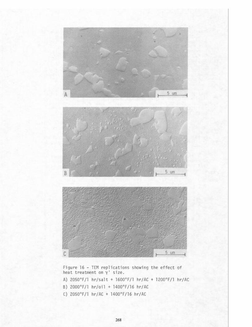
The TEM replica technique was used to evaluate the Y' characteristics for these three heat treatment conditions. Figure 76 shows TEM replica micrographs which illustrate their primary and intermediate Y ' features. The primary Y ' sizes were similar and ranged from one to three microns in size. The volume fraction, however, increased with decreasing solution temperature. The intermediate Y I forms on cooling from the solution temperature. The more rapid the cooling, the finer the size and distribution. Heat treatment C, air cooled from the annealing temperature, resulted in the largest intermediate Y', measuring approximately 0.2 microns in size. The quenched materials had smaller intermediate Y ' measuring approximately 0.05 microns in size.
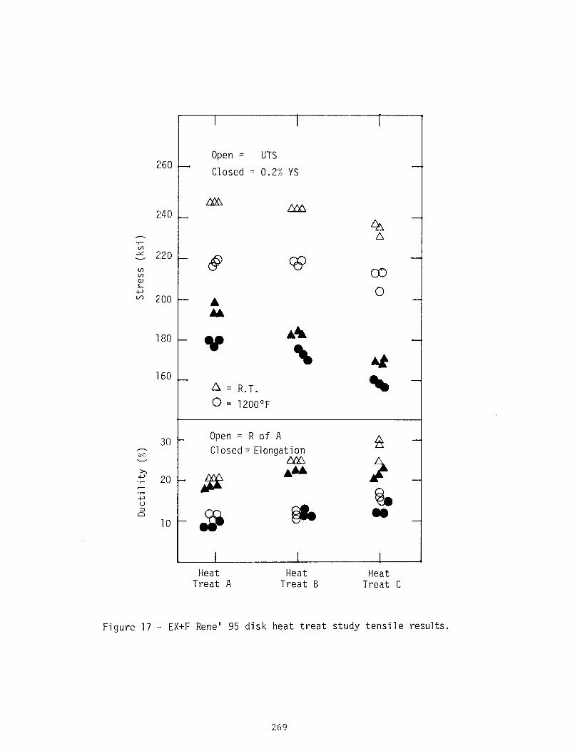
Specimens from each heat treatment condition were prepared for a tensile, rupture and creep property comparison. Figure 17 shows the tensile data obtained for room temperature and 1200°F test conditions. The data show that slow cooling results in lower strength but higher ductility. The ductility of a77 three heat treatments is generally better than HIP Rene' 95 heat treated to similar strength levels.
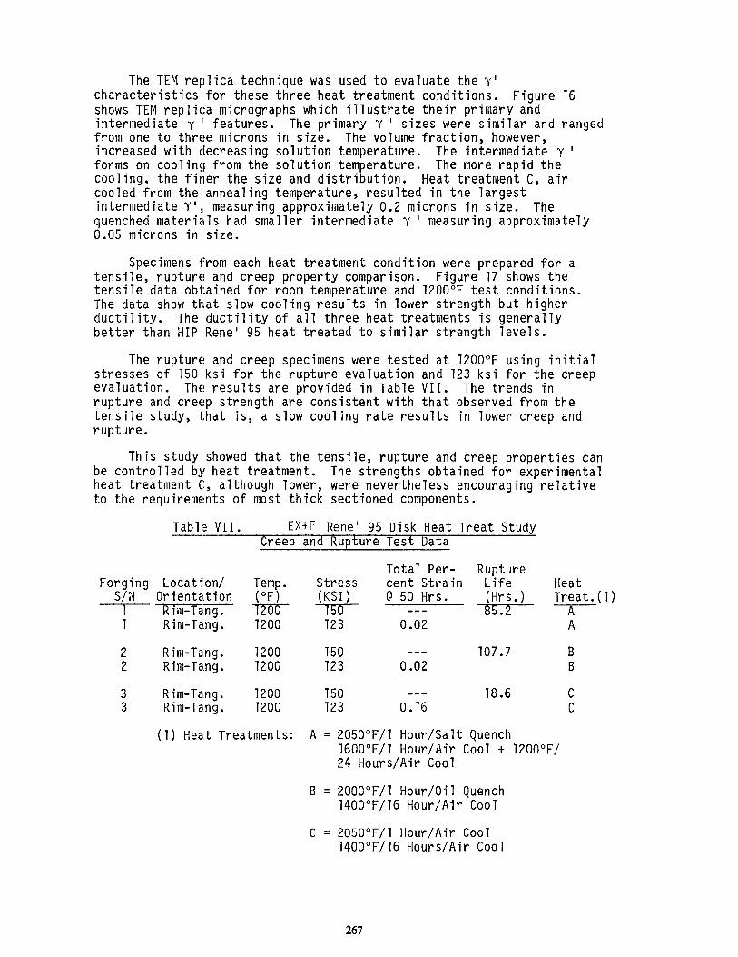
The rupture and creep specimens were tested at 1200°F using initial stresses of 150 ksi for the rupture evaluation and 123 ksi for the creep evaluation. The results are provided in Table VII. The trends in rupture and creep strength are consistent with that observed from the tensile study, that is, a slow cooling rate results in lower creep and rupture.
This study showed that the tensile, rupture and creep properties can be controlled by heat treatment. The strengths obtained for experimental heat treatment C, although lower, were nevertheless encouraging relative to the requirements of most thick sectioned components.
Table VII. EX+F Rene' 95 Disk Heat Treat Study Creep and Rupture Test Data
Forging Location/ S/N Orientation
1 Rim-Tang. 1 Rim-Tang.
2 Rim-Tang. 2 Rim-Tang.
3 Rim-Tang. 3 Rim-Tang.
Total Per- Temo. Stress cent Strain (“Fj (KS1 ) @ 50 Hrs. -lmD-- --l-in- --- 1200 123 0.02
1200 750 --- 1200 123 0.02
1200 750 -a- 78.6 C 1200 123 0.16 C
Rupture Life Heat (Hrs.) Treat. 3. 1 2 A
A
107.7 B B
(1) Heat Treatments: A = 205O"F/l Hour/Salt Quench 16OO"F/l Hour/Air Cool + lZOO"F/ 24 Hours/Air Cool
B = ZOOO"F/l Hour/Oil Quench 1400°F/16 Hour/Air Cool
C = 205O"F/l Hour/Air Cool 1400°F/16 Hours/Air Cool
1)
267
, ,:* / ‘* 1’1 II .‘SL ,iw”y. ,“^-q..j
Figure 16 - TEM replications showing the effect of heat treatment on y' size.
A) 205O"F/l hr/salt + 16OO"F/l hr/AC + 12OO"F/l hr/AC
B) 2000°F/1 hr/oil + 14OO"F/16 hr/AC
C) 2050°F/1 hr/AC + 14OO"F/16 hr/AC
268
2160
240
180 t-
160
30
20
10
I I
Open = UTS
Closed = 0.2% YS
l? Ah
\ At
a = R.T. \
0 = 1200°F
Open = R of A Closed= Elongation
-ii@
.s
* - sp
I I I
:
Heat Heat Heat Treat A Treat B Treat C
__ EX+F Rene' 95 disk heat treat study tensile results.
269
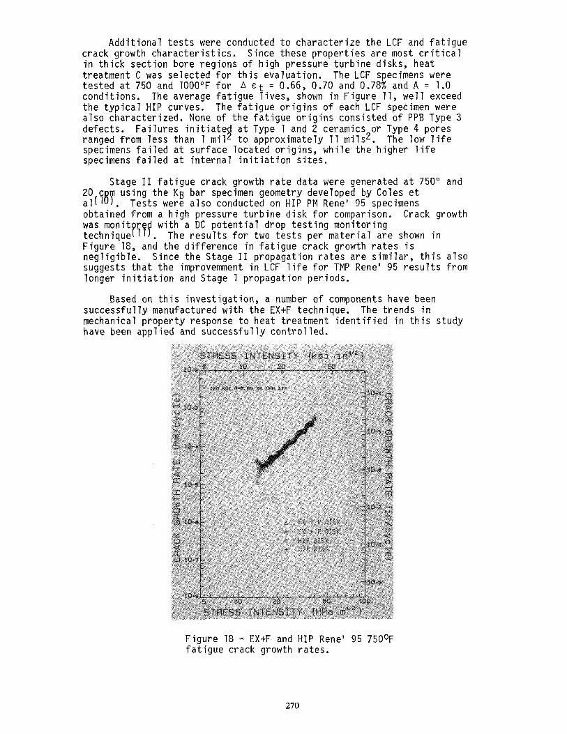
Additional tests were conducted to characterize the LCF and fatigue crack growth characteristics. Since these properties are most critical in thick section bore regions of high pressure turbine disks, heat treatment C was selected for this evaluation. The LCF specimens were tested at 750 and 1000°F for A ct = 0.66, 0.70 and 0.78% and A = 1.0 conditions. The average fatigue lives, shown in Figure 11, well exceed the typical HIP curves. The fatigue origins of each LCF specimen were also characterized. None of the fatigue origins consisted of PPB Type 3 defects. Failures initiated at Type 1 and 2 ceramics or Type 4 pores ranged from less than 1 mi12 to approximately 11 mils2. The low life specimens failed at surface located origins, while the higher life specimens failed at internal initiation sites.
Stage II fatigue crack growth rate data were generated at 750" and 20 c aJ(J . BY
using the KB bar specimen geometry developed by Coles et Tests were also conducted on HIP PM Rene' 95 specimens
obtained from a high pressure turbine disk for comparison. Crack growth was monit r technique 1 . P Tf
with a DC potential drop testing monitoring The results for two tests per material are shown in
Figure 18, and the difference in fatigue crack growth rates is negligible. Since the Stage II propagation rates are similar, this also suggests that the improvemment in LCF life for TMP Rene' 95 results from longer initiation and Stage 1 propagation periods.
Based on this investigation, a number of components have been successfully manufactured with the EXtF technique. The trends in mechanical property response to heat treatment identified in this study have been applied and successfully controlled.
Figure 18 - EXtF and HIP Rene' 95 750°F fatigue crack growth rates.
270

Conclusions and Future Directions
Results from the investigations referenced in this paper have demonstrated that TMP can significantly reduce and disperse defects thereby improving the LCF properties of nickel base PM superalloys. It has also been demonstrated that the detrimental effects of large reactive defects (PPB) can be eliminated by certain TMP techniques. The refined grain size of TMP material also enhanced the ultrasonic inspectability. This permits maIre stringent quality control practice. These combined improvements permit industry to place further confidence in the reliability and integrity of high strength PM superalloys.
However, the LCF lives of TMP PM material are still limited by Type 1 and Type 2 ceramic inclusions. Substantial additional component life benefits can be realized, but much further effort is required to reduce or eliminate these defects. This can be achieved by using clean melted input stock material followed by a ceramicless powder atomization process. Programs sponsored by various government agencies and industries are in place to develop clean melting and cl an processes. Preliminary results from these developments PJ2)T~~Ye~ave been encouraging. Since the LCF life is also limited by surface initiated failure, surface enhancement techniques which are capable of generating a surface compressive stress layer to inhibit surface failure should be applied. t has been effectively demonstrated by a
Th'tlmS. number of investigators Alloy development activities to modify composition and improve the intrinsic defect tolerance of the materials are also needed. These compositional modifications must consider nd al nce all other properties for engine applications. Programs 7 l6 17 have been initiated to address this challenging goal. 1'1 B
Powder metallurgy technology is a cost effective means to produce highly alloyed compositions with the desired mechanical properties. As powder quality, availability and manufacturing techniques improve, implementation is expected to increase significantly. For jet engine applications, powder superalloy usage is projected to increase to meet the higher property and life requirements of future engines.
Acknowledgements
The authors are indebted to the following individuals of the General Electric Company: Mr. C. Shamblen for his work on defect characterization, Mr. H. Green and Mr. D. Mourer for their contribution in doped material evaluation, and Dr. W. Chang for reviewing the manuscript. The authors are most indebted to several of our powder, consolidation, and forging suppliers for their dedicated effort toward achieving excellence in their products and their efforts related to this paper. We also' wish to acknowledge parallel PM efforts conducted by AFWAL and NASA at their facilities in support of this and our more generic efforts.
271
References
Private Communication, E. Hall, Corporate Research and Development Center, General Electric Company, September, 1982.
1.
2.
3
4.
5.
6.
7.
8.
9.
10.
11.
12.
C.E. Shamblen and D.R. Chang, "Effect of Inclusions on LCF Properties of As-HIP Rene' 95" , paper presented at TMS Fall Meeting - High Temperature Alloys Committee of AIME, Philadelphia, Pa., October, 1983.
W.H. Chang, H.M. Green, and R.A. Sprague, "Defect Analyses of P/M Superalloyst~, Rapid Solidification'Processing Principles and Technologies III, Ed. R. Mehrabian, Proceedings of the Third Conference onxpid Solidification Processing, Bureau of Standards, December 8, 1982; pp. 500-509.
Private Communication, M.F. Henry, Corporate Research and Development Center, General Electric Company, September, 1981.
S. Floreen and R.H. Kane, "An Investigation of the Creep-Fatigue- Environmental Interaction in a Ni-Base Superalloy", INCO Research and Development Center, Technical Paper 1020-T-OP, Suffern, New York, August, 1979.
L.F. Coffin, "The Effect of High Vacuum on Low Cycle Fatigue Law", Met. Trans., 3, 1972, pp. 1777.
R.V. Miner, J. Gayda, "Effects of Processing and Microstructure on the Fatigue Behavior of the Nickel-Base Superalloy Rene' 95", paper presented at TMS Fall Meeting - High Temperature Alloys Committee of AIME, Philadelphia, Pa., October 3, 1983.
C.E. Shamblen, R.E. Allen, and F.E. Walker, "Effect of Processing and Microstructure on Rene' 95", Met. Trans., 6A November, 1975; pp. 2073-2082.
-'
R.H. VanStone, "Processing Effects on Microstructure and Fatigue Properties of Nickel-Base Superalloys", Final Report, NADC 80124-60, General Electric Company, December, 1980.
A. Coles, R.E. Johnson, and H.G. Popp, "Utility of Surface Flawed Tensile Bars in Cyclic Life Studies", J. Eng. Mat. Tech., 98, 1976, pp. 305.
R.P. Gangloff, "Electrical Potential Monitoring of Crack Formation and Subcritical Growth from Small Defects", Fatigue of Engineering Materials and Structures, 4, 1981, pp. 15.
C.E. Shamblen, S.L. Gulp, and R.W. Lober, “Superalloy Cleanliness Evaluation Usincl the EB Button Melt Test". Proceedina of the
_-
Conference Eleciron Beam Melting and Refining State ?Art l-983, Ed. Library of Congress ISSN 0740-8706, November 6-8, 1983,
272
13. E.E. Brown, (I.E. Stulga, L. Jennings, and R.W. Salkeld, "The Influence of VIM Crucible Composition, Vacuum Arc Remelting, and Electra Slag Remelting on the Non-Metallic Inclusion Content of MERL-76", Su],eralloys 1980, Eds. J.K. Tien, et al., American Society for Metals, Metals Park,hio, 1980, pp. 159-168.
14. W. Renzhi, "'Shot Peening of Superalloy and its Fatigue Properties at Elevated Temperature", First International Conference on Shot Peening, Paris, September, 1981 , Pergomon Press, Oxford, pp. 395.
15. B.D. Boggs and J.G. Byrne, "Fatigue Stabiity of Residual Stress in Shot Peened Alloys", Met. Trans., 4, September, 1973, pp. 2153-2157.
16. J.C. Williams and J.P. Hirth, "Microstructure-Property Relations and Their Role in RSP Materials", Ibid. 3, pp. 135-149.
17. A.M. Adair, L.A. Jacobson, E.C. VanReuth, and J. Dickson, "Rapid Solidification - Past Promises and Current Reality," Ibid. 3, pp. 609-614.
273