Embed Size (px)
Citation preview
MELTING AND REFINING TECHNOLOGY OF HIGH-TEMPERATURE STEELS AND SUPERALLOYS
A REVIEW OF RECENT PROCESS DEVELOPMENTS
R. Schlatter Latrobe Steel Company, Latrobe, Pennsylvania
Abstract
The recent increase in number and capacity of special melting techniques and refi ning processes is related to the continuing growth of high-temperature alloy usage in wrought and cast form and to the fact that the metallurgical and technological potential of conventional melting and casting processes have been largely exhausted. The evol ution of the major melting processes for high-performance materials and the increasing trend toward separation of rnodern melting and refining operations into distinctive indi vidual functions for maximum utilization of each unit are outlined. Use of auxiliary re equipment after air melting is most attractive for producers of specialty steels
fining but
has also found application for nickel-base alloys. Some of the more sophisticated auxiliary refining technologies are described in the light of their capability of per- forming multiple functions, like degassing, desulfurization, carbon deoxidation, pre- cise alloying, and decarburization.
Metallurgical process characteristics, principal features and shortcomings of various production and pilot melting techniques are discussed and compared with each other on the basis of their technological potential. The present wrought alloy manufacturing processes provide flexibility in the selection of the most suitable combination of specific melting processes for the large variety of alloys to achieve the best material quality most economically. Emphasis is placed on the technology of the most important double vacuum melting process which combines vacuum induction melting and vacuum arc remelting. Electraflux remelting - in combination with air melting or vacuum induction melting - is increasingly used as an alternative process to vacuum arc remelting for certain alloys. Metallurgical, operational, and quality aspects of the widely used production melting techniques are discussed regarding raw material selection, compo- sition and impurity control, refining capabilities, and control of ingot structures. Additionally, electron beam melting, which is in limited production use today for high- temperature alloys, and the promisin tensive development are considered. 1
plasma arc melting process presently under in- n outlook into the future position of the various
melting and refining schemes conclude the review.
1. Introduction
High-temperature steels and superalloys in general represent a class of materials which provide very useful strength capabilities at temperatures above 550°C (1022°F). Super- alloys may be broadly defined as alloys with excellent oxidation resistance for service at high-stress levels at temperatures exceeding 650°C (1202°F). One convenient classi- fication of high temperature alloys into four groups is shown in Table 1.
The recent increase in number and capacity of special melting and refining techniques is not only related to the continuing growth of high temperature alloy usage in wrought and cast form, but also to the fact that the matallurgical potential of conventional melting and casting processes have been largely exhausted. Increasingly tougher material specifications and steadily growing demands for improved product performance and reli- ability are responsible for the intensified development of new melting and refining schemes. Specialized processes are aimed at high-performance materials to improve work- ing and fabricating characteristics, and to consistently produce better mechanical and
A-l
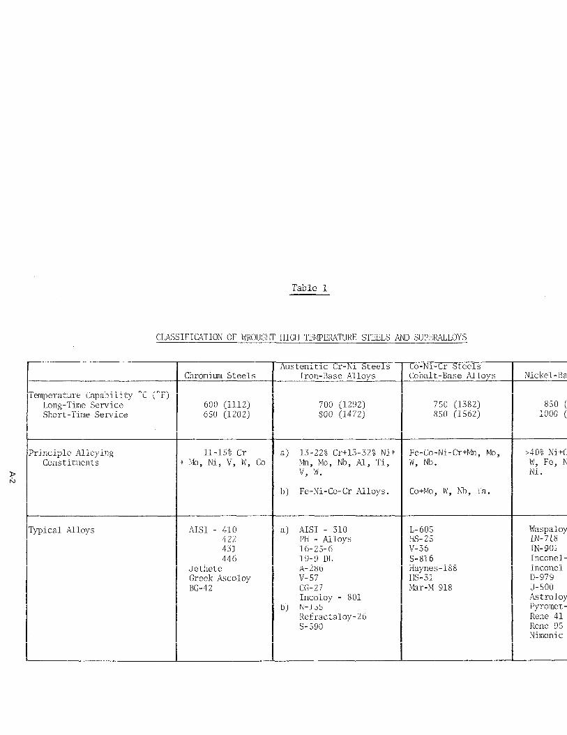
CLASSIFICATION OF WROUGIlT HIGH TBlPERATURE STEELS AND SUPERALLOYS
9 rc,
'emperature Capability "C (OF) Long-Time Service Short-Time Service
'rinciple Alloying Constituents
a) 13-22% Cr+l3-32% Ni+ Fe-Co-Ni-Cr+Mn, MO, >40% Ni+Cr, 1M0, Cq + MO, Ni, V, W, Co
b) Fe-Ni-Co-Cr Alloys. Co+Mo, W, Nb, Ta.
'ypical Alloys a) AISI - 310
Inconel X-750
Refractaloy-26
Astroloy, U-700
Nimonic Alloys
technological properties at the lowest possible cost. The trend toward separation of melting and refining operations into distinctive individual functions for maximum flex- ibility and metallurgical utilization of each unit has led to the establishment of rather complex "melting systems".
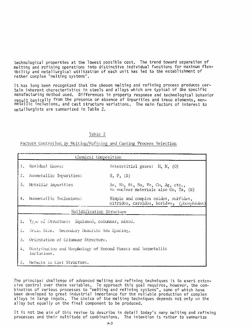
It has long been recognized that the chosen melting and refining process produces cer- tain inherent characteristics in steels and alloys which are typical of the specific manufacturing method used. Differences in property response and technological behavior result basically from the presence or absence of impurities and trace elements, non- metallic inclusions, and cast structure variations. The main factors of interest to metallurgists are summarized in Table 2.
Table 2
Factors Controlled By Melting/Refining and Casting Process Selection
-. Chemical Composition
1. Residual Gases: Interstitial gases: H, N, (0)
2. Nonmetallic Impurities: s, p, @I
3. Metallic Impurities As, Sb, Bi, Su, Pb, Cu, Ag, etc., in nuclear materials also Co, Ta, (B)
4. Nonmetallic Inclusions: Simple and complex oxides, sulfides, nitrides, carbides, borides, (phosphides I,..- _
Solidification Structure -.
1. ‘r;!.:Jti of Structure: Equiaxed, columnar, mixed.
2. Grain Size. Secondary Dendrite Am11 Spacing.
3. Orientation of Cclumriar Structure.
4. Distribution and Morphology of Second Pilases and Nonmetallic Inclusions.
5. Defects in Cast Structure.
The principal challenge of advanced melting and refining techniques is to exert exten- sive control over these variables. To approach this goal requires, however, the com- bination of various processes to "melting and refining systems", some of which have been developed to great industrial importance for the reliable production of complex alloys in large ingots. The choice of the melting techniques depends not only on the alloy but equally on the final component to be produced.
It is not the aim of this review to describe in detail today's many melting and refining processes and their multitude of combinations. The intention is rather to summarize
A-3
simply the principal capabilities and limitations of various techniques with particular reference to those schemes which achieved industrial prominence in the manufacture of wrought high-temperature steels and superalloys.
2. General Considerations
Basically, an ideal melting and casting process should provide:
(1) a clean and consistent end product with lowest contents of gases, impurities, nonmetallic inclusions;
(2),j excellent control of chemical composition and high, predictable recovery of alloying elements;
[ii exact control over efficient and fast refining reactions; no contamination from container and atomsphere;
(5) flexibility and adaptability for many alloys and raw materials; (6) good control of solidification process; (7) high reliability and productivity at low operating cost.
It is an impossible task to combine these requirements in one melting,refining, and casting unit, although attempts have been made in this direction. The principal melting methods for specialty alloys are best divided into primary and secondary processes. Primary melting techniques are aimed at "making" or "synthesizing" the alloys from pure metals, master alloys, revert, and scrap material. Flexibility in raw material selec- tion, precise and reliable control of the entire alloy chemistry, rapid mixing, ex- tensive refining, and a minimum or absence of crucible/atmosphere interaction are crit- ical factors in this initial step of alloy making.
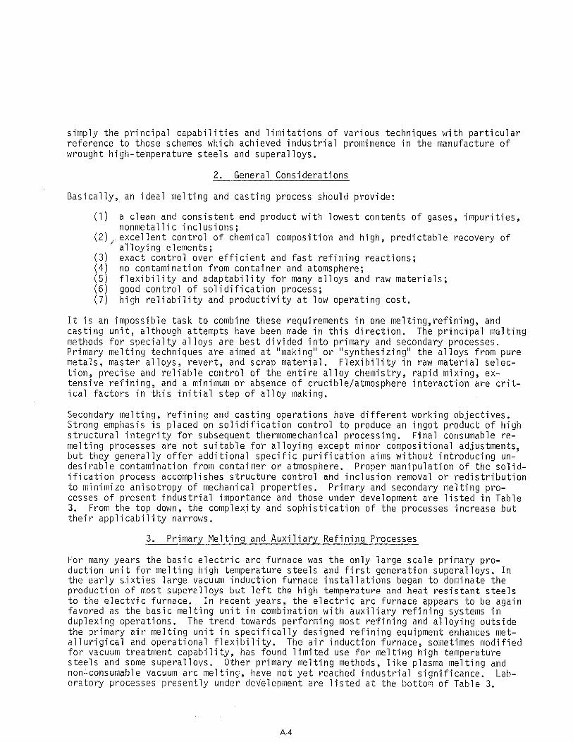
Secondary melting, refining and casting operations have different working objectives. Strong emphasis is placed on solidification control to produce an ingot product of high structural integrity for subsequent thermomechanical processing. Final consumable re- melting processes are not suitable for alloying except minor compositional adjustments, but they generally offer additional specific purification aims without introducing un- desirable contamination from container or atmosphere. Proper manipulation of the solid- ification process accomplishes structure control and inclusion removal or redistribution to minimize anisotropy of mechanical properties. Primary and secondary melting pro- cesses of present industrial importance and those under development are listed in Table 3. From the top down, the complexity and sophistication of the processes increase but their applicability narrows.
3. Primary Melting and Auxiliary Refining Processes
For many years the basic electric arc furnace was the only large scale primary pro- duction unit for melting high temperature steels and first generation superalloys. In the early sixties large vacuum induction furnace installations began to dominate the production of most superalloys but left the high temperature and heat resistant steels to the electric furnace. In recent years, the electric arc furnace appears to be again favored as the basic melting unit in combination with auxiliary refining systems in duplexing operations. The trend towards performing most refining and alloying outside the primary air melting unit in specifically designed refining equipment enhances met- allurigical and operational flexibility. The air induction furnace, sometimes modified for vacuum treatment capability, has found limited use for melting high temperature steels and some superallovs. Other primary melting methods, like plasma melting and non-consumable vacuum arc melting, have not yet reached industrial significance. Lab- oratory processes presently under development are listed at the bottom of Table 3.
A-4
Table 3
Melting anti Refining Processes for Wrought Superalloys <and I!igh Temperature Steels
able kiting + Control- ogressive Solidif-
1ir Arc Melting (AM) Perrin-Slag-Reaction Process
EA-SKF Process - Normal Atmosphere - Inert Gas
carburization
Continuous Casting
In Reactor Vessel: - Inert Gas
a Arc Remelting (PAR)
4ir Induction
Melting (VIM)
3.1 Basic Electric Arc Melting
Basic electric arc furnaces have--despite obvious shortcomings--always retained some importance for early generation superalloys and, of course, many high temperature steels. With the recent strong trend to duplexing operations, the electric furnace has been chosen as basic melting unit, but refining and alloying are carried out more exactly and efficiently in separate auxiliary installations. Principal features of the electric arc furnace are:
(1) wide flexibility in charge material conditions (2) good temperature and easy operational control (3) hot, reactive slag for intensive metallurgical work (4) slag reactions .adaptable to particular needs (5) high productivity and efficiency, low melting cost
The main disadvantages concern the presence of graphite electrodes, the shallow bath and lack of good stirring leading to long refining times and poor melt homogenization. Modifications of the melting technology, improved equipment design, application of com- puters for charge material, furnace, and process control, and the advent of using sep- arate refining facilities revived the electric arc furnace and made it technically and operationally more attractive. The duplexing practice was first introduced at Latrobe Steel Company by charging the evacuated 30-ton Therm-I-Vat furnace with prerefined, hot metal from basic electric furnaces for subsequent refining, alloying, and casting under vacuum. Today, a number of vacuum refining systems are in use which primarily evolved from various degassing methods. However, these developments generally do not provide complete handling of the melt under vacuum or protective inert atmosphere, and are thus limited in their application for superalloys.
Several basic arc melting practices for complex high temperature alloys have been de- veloped and specialty steelmakers carefully tailor the working procedures to specific material requirements(l). Induction stirring equipment is indispensible on modern arc furnaces to provide such important advantages as better homogenization of the bath, in- creased temperature uniformi
t9 more complete and rapid slag removal, and accelerated
slag-metal reaction kinetics . Improvements in oxygen lancing techniques and the use of optimum oxygen injection rates allow a shorter, better controlled, and more efficient oxidation period. The development of rapid oxygen determination in the bath by solid electrolyte sensors is a most useful control tool to avoid overblowing and to monitor the reducing a shorter melting cycles 1 )
9 deoxidation treatment for improved product consistency and . Long refining periods under highly basic slags are best
avoided to minimize hydrogen pickup and refractory erosion causing quality problems. Most effective and efficient in the production of premium quality steels and alloys with good cleanliness is the injection of slag components, deoxidation agents, and minor alloying ingredients by special water-cooled roof lances using inert carrier gases. This method greatly accelerates metal-slag reactions resulting in dephosphorization, rapid desulfurization, and consistently low oxygen contents coupled with high recoveries of alloying elements. Additionally, these special lances can be used for inert gas purging and stirring of the melt to enhance hydrogen removal and precipitation of oxide suspensions. Particular attention must be given to the final deoxidation treatment which is the most important phase in electric furnace steelmaking.
Gas treatments can be continued during tapping and holding the melt in the ladle by argon injection h u h a porous bottom plug which has a mild degassing and favorable cleansing effectt4rT5y. Another technique in limited u e for the production of cl,eaner steel is known as the Perrin or slag-reaction process (65 which consists of treating the molten steel during reladling or tapping with synthetic molten calcium aluminate slag from another furnace. Often a simplified slag reaction practice is employed by
A-6
first tapping the refi:ning slag and then the melt from the furnace. Either method im- proves slag-metal interaction rates markedly, thus favoring desulfurization and flo- tation of nonmetallic inclusion suspensions.
The subsequent vacuum degassing and deoxidation treatment of electric furnace heats has attained great industrial importance in specialty steel production. A wide variety of large scale degassing techniques have been developed over the past two decades. A description of them would be beyond the s o e of this review and the reader is referred to the extensive literature in this field 7 . 7'3 Those techniques capable of performing a multitude of refining treatments will be briefly discussed later.
The presence of graphite electrodes may be considered undesirable to attain low carbon levels but the real drawback of electric furnace melting--and equally inherent to the present auxiliary refining systems-- lies in tapping and teeming the heats in air which leads to gas pickup, poor microcleanliness due to oxidation, and inconsistencies in composition control. Inexpensive and reliable practices to tap and teem in inert at- mosphere are not yet develo e Gero vacuum casting process % a?
but will be needed in the future. Techniques like the and inert atmosphere casting of ingots and electrodes
have not found industrial acceptance although they have proven their usefulness. The application of simple argon shrouds around the teeming stream is generally inefficient and must be replaced by better techniques.
3.2. Auxiliary Primary Refining Processes
Vacuum degassing treatments, primarily for hydrogen removal, were introduced during the first stage of upgrading the quality of electric furnace steels. Soon followed carbon deoxidation and compositional adjustments under vacuum. More complex metal- lurgical technologies developed subsequently, leading to vacuum oxygen-decarburization of high chromium steels and intensive slag treatments in specially designed equipment under closely controlled conditions. The original idea of dividing the steelmaking procedure into two parts-- meltdown, oxidation, and dephosphorization in conventional electric arc furnaces,, and refining treatment under reducing conditions in separate units--resulted in an array of new metallurgical practices. The argon-oxygen decarbur- ization technique developed by Linde and Joslyn has just emerged as a process of revolutionary significance in stainless steelmaking and outstanding potential in pro- ducing nickel and other alloys requiring very low carbon contents.
3.2.1. Vacuum Refining Processes
These supplementary processes have in common the exposure of un-or semi-refined electric furnace melts in the teeming ladle to reduced pressures in a separate vessel or by placing a vacuum tight cover over the ladle. Advanced refining units are equipped with additional heating devices to provide the necessary process flexibility. Many modifications of the basic vacuum treatment exist; all generally permit a number of metallurgical operations to be carried out in different sequences as required by the wide variety of materials being refined.
The Finkl-VA&Vacuum Arc Degassing process (9) represents a significant upgrading of the original Finkl-Mohr ladle degassing technique using now three-phase AC electric arc heating while degassing and stirring the melt by argon injection. Refining is carried out in the teeming ladle; desulfurization slag treatment or vacuum decarbu- rization can be incorporated since arc heating and effective stirring by argon purging provide favorable conditions for these additional metallurgical operations.
The Lectromelt-LVR-Vacuum Induction Refining technique is an outgrowth of the DH de- gassing process whereby the heat input is provided by an induction coil surrounding the lower portion of a modified DH vessel. Degassing, decarburization, and alloying
A-7
b,lder vacuum with .inductive stirring are the principal capabilities of this process but slag treatments are not possible. The LVR techniques has not yet found industrial application. Similar modifications are also conceivable for the RH circulation de- gassing method.
The Witten-(LD)Elo-Vat process (")developed in Germany by Edelstahlwerke Witten (and similarly Republic Steel's VOD process) to vacuum decarburize high chromium steels consists of a ladle degassing unit featuring oxygen 1 n stirring through a porous bottom plug (Gazid process u
ing onto the melt surface, 5 ), and teeming control by a
argon
slide gate nozzle. No external heating source is provided because the increase of the bath temperature of about 50°C (122°F) is controlled by the chemical reaction heat during the oxidizing vacuum treatment to carbon contents of ~0.02% with an average chromium recovery of about 98%. The oxygen-decarburization process is also applicable to cycling and circulation vacuum degassing systems.
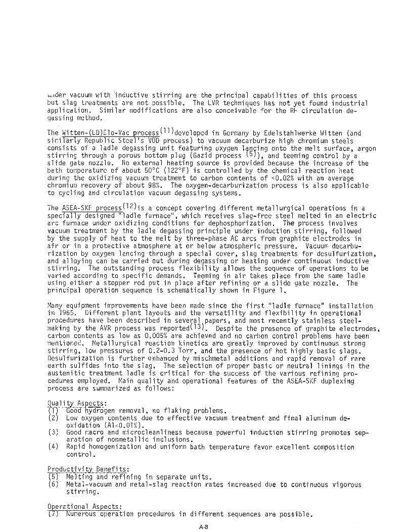
The ASEA-SKF process(12)* 1s a concept covering different metallurgical operations in a specially designed "ladle furnace", which receives slag-free steel melted in an electric arc furnace under oxidizing conditions for dephosphorization. The process involves vacuum treatment by the ladle degassing principle under induction stirring, followed by the supply of heat to the melt by three-phase AC arcs from graphite electrodes in air or in a protective atmosphere at or below atmospheric pressure. Vacuum decarbu- rization by oxygen lancing through a special cover, slag treatments for desulfurization, and alloying can be carried out during degassing or heating under continuous inductive stirring. The outstanding process flexibility allows the sequence of operations to be varied according to specific demands. Teeming in air takes place from the same ladle using either a stopper rod put in place after refining or a slide gate nozzle. The principal operation sequence is schematically shown in Figure 1.
Many equipment improvements have been made since the first "ladle furnace" installation in 1965. Different plant layouts and the versatility and flexibility in operational procedures have been described in several papers, making by the AVR process was reported(T3).
and most recently stainless steel- Despite the presence of graphite electrodes,
carbon contents as low as 0.005% are achieved and no carbon control problems have been mentioned. Metallurgical reaction kinetics are greatly improved by continuous strong stirring, low pressures of 0.2-0.3 Torr, and the presence of hot highly basic slags. Desulfurization is further enhanced by mischmetal additions and rapid removal of rare earth sulfides into the slag. The selection of proper basic or neutral linings in the austenitic treatment ladle is critical for the success of the various refining pro- cedures employed. Main quality and operational features of the ASEA-SKF duplexing process are summarized as follows:
-ien removal no flaking problems (2) Low oxygen contents dhe to effective vacuum treatment and final aluminum de-
oxidation (Al<O.Ol%). (3) Good macro and microcleanliness because powerful induction stirrino Promotes sep- . I
aration of nonmetallic inclusions. (4) Rapid homogenization and uniform bath temperature favor excellent compos
control. tion
Productivity Benefits: ( ) Melting and refining in separate units (i) Metal-vacuum and metal-slag reaction rates increased due to continuous v
stirring. gorous
Operational Aspects: (7) Numerous operation procedures in different sequences are possible.
A-8
AIR-LOCK i .n
ADDITIONS HrlPPFR
ADDITIONS
TAPPING VACUUM
TREATING HEATING
Figure A-1. ASEA-SKF Steel Refining.
A-Q
(8) Heating between various steps allows treatment times to be extended with excellent temperature control,
(9) Reactive gas and slag treatments are possible. (10) Wide variety of steels and alloys can be upgraded significantly.
In a further development, the ASEA-SKF process has recently been combined with the new SKF do bl electric arc furnace concept to form the "SKF-MR Melting and Refining" systemYl4e.
3.2.2. Argon-Oxygen Process
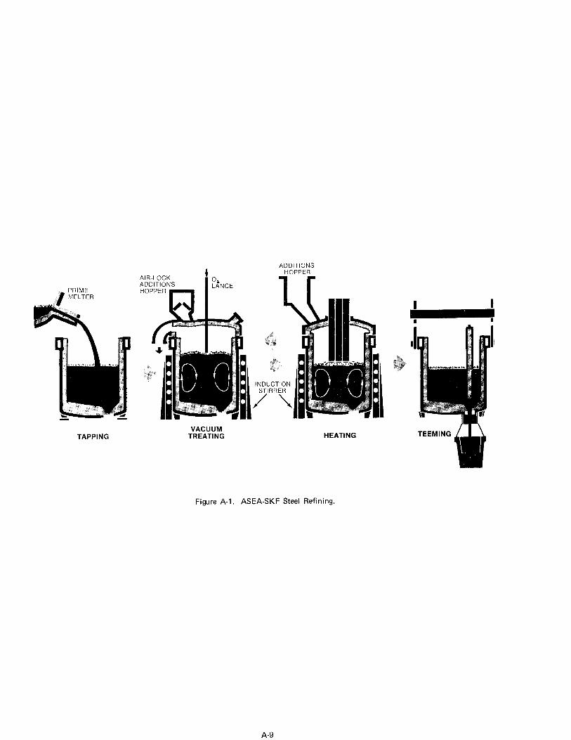
The principal processes of decarburization high chromium steels are schematically shown in the chromium-carbon and oxygen-carbon equilibrium diagrams of Figure 2. With con- ventional oxygen blowing in electric furnaces very high process temperatures are re- quired to attain low carbon contents, but high chromium losses and e'xcessive refractory wear are encountered. Some oxidized chromium is recovered and the oxygen level accept- ably lowered by the subsequent reduction treatment. Much more favorable decarburization conditions are established by lowering the carbon monoxide partial pressure to enhance the carbon-oxygen reaction. Two new processes make use of this fact: oxygen lancing under vacuum with simultaneous stirring the melt inductively or with argon, and blowing the melt in a specially designed reaction vessel with controlled argon-oxygen mixtures. High process temperatures are avoided in either case, as illustrated in Figure 2, but low carbon contents of ~0.02% are easily and economically attained at very small chro- mium losses. These brief considerations are fundamental to the new revolutionary stain- less steelmaking technology.
Since the first UC essful Stainless Steels l5 'i i
commercial argon-oxygen vessel installation in 196% at Joslyn the AOD process has been spreading rapidly because of its simplicity
and flexibility of operation, its easy control and reproductibility, and its superior product quality over conventional practices. Duplex processing marks a new era in stainless steelmaking whereby an alloy and scrap charge is melted in the basic electric furnace to the melt-in composition of the type stainless being produced - except for C, Si, and S. The heat is then transferred slag-free to the reactor and a basic slag added. After rotating the ladle-like vessel (converter) to the vertical position, an argon-oxygen mixture (1:3 to 2:3) is injected into the bath through 2-4 tuyeres located at the bottom back wall of the reactor. Excellent control over reaction rate and equi- librium is provided by variation the argon-oxygen ratio from 1:3 to 3:l to maintain a low CO partial pressure. This procedure allows for a decarburization stage, a reduction stage by adding limeferrosilicon reduction mixtures , and a refining stage that also serves to stir in any corrective alloy additions. The sequence of operations is illus- trated schematically in Figure 3. After refining, the heat is tapped into a ladle for normal teeming into ingots. A number of unique features characterize this process: regardless of the starting carbon and chromium levels, it is possible to decarburize efficiently to any desired carbon content with exact control and reproducibility, re- cover 97-99% of the chromium, and keep the bath temperature below a maximum of about 3200°F (1760°C). Desulfurization is easily accomplished by adding a new basic slag during refining. The simple construction of the AOD vessel is free of maintenance or operating problems. Two areas are of concern only: the refractory lining (usually direct bonded 50-60% magnesite-chrome bricks), and adequate (air) cooling of the tuyeres. A disadvantage of the process is the high argon consumption but developments are under- way to partially substitute nitrogen for argon.
While most AOD activity involves stainless steels, much progress has also b en made with processing corrosion resistant and high temperature nickel-base alloys I; 1 16 . Three AOD vessels ranging in capacity from 5 to 3% tons are presently teamed up with electric arc furnaces for the production of alloys with high chromium contents and carbon levels
A-10
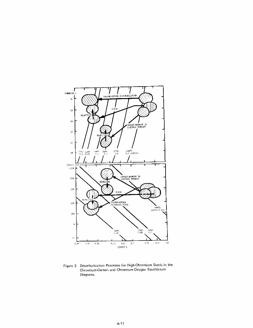
Kgure 2. Decarburization Processes for High-Chromium Steels in the Chromium-Carbon and Chromium-Oxygen Equilibrium Diagrams.
A-11
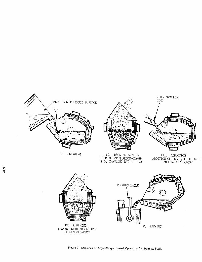
/ MELT FROM ELECTRIC FURNACE
I. CHARGING
IV. REFINING BLOWING WITH ARGON ONLY
DESLJLFLJRIZATION
REDUCTION MIX
II. DECARBURIZATION BLOWING WITH ARGON/OXYGEN 1:3, CHANGING RATIO TO 3:l
TEEMING LADLE
III. REDUCTION ADDITION OF FE-SI, FE-CR-S1 + LIME
MIXING WITH ARGON
V. TAPPING
Figure 3. Sequence of Argon-Oxygen Vessel Operation for Stainless Steel.
of 0.005 to 0.02%. The use of all scrap heats and the wide technological flexibility of this process are very attractive to alloy producers.
Principal advantages of the AOD process are:
Quality Aspects: (1) Hydrogen decreased to low levels. (2) Nitrogen content can be reduced, maintained, or increased. [;I (ll;ien levels are lowered significantly.
is effectively removed to <O.OOl%. (5) No large inclusions, very uniform distribution of remaining small nonmetallic
inclusions. (6) Excellent bath homogenization, hence precise composition control to meet narrow
ranges.
Productivity Benefits: ( ) Melting and refining in separate units (i) Very favorable rleaction kinetics during decarburization and desulfurization due
to vigorous argon stirring.
Operational Aspects:
(9) Excellent temperature control by adjusting gas input, Ar/02 ratio, and silicon additions.
(10) Operation sequences can be extensively modified. (11) Outstanding reproducibility. (12) Wide variety of iron-and nickel-base alloys can be processed.
3.3. Vacuum Induction Melting
Vacuum induction melting has a long and exciting history of development from a crude laboratory curiosity to today's dominant position as the most important primary melting and refining process for superalloys and many high temperature steels which must meet consistently very stringent material specifications. Quality improvements obtained by "vacuum melting" are far beyond those achieved by vacuum degassing processes in re- gard to technological
(es;gfPEf': es * The key advantages of the VIM process have been dis-
cussed in many papers Compared with other industrial melting techniques, VIM provides very flexible operation in absence of air and the best control over the entire melt chemistry, such as exact control of complex alloy compositions, beneficial trace elements, and harmful impurities. It appears feasible today to improve the mechanical properties of superalloys by closely controlling residual elements rather than attempting to remove them completely. The reproducibility of precise compositions from heat-to- heat approaches for some elements the accuracy limits of present analytical techniques, as indicated in Table 4 for a nickel-base alloy (19). This exceptional control capa- bility results in a remarkable consistency of material properties at high levels. These features represent the most important metallurgical and production justifications for VIM despite that it is a relatively expensive operation even in large furnaces of advanced design.
The high degree of flexibility and compositional control is derived from the following process characteristics:
(1) Isolation of melt from atmospheric contamination; furnace atmosphere can be se- lected within wide limits from high vacuum to inert or reactive gases, allowing the system to be treated in a truly thermodynamic sense. (2) Control of pressure permits exceptional degassing, strong carbon deoxidation,
A-13
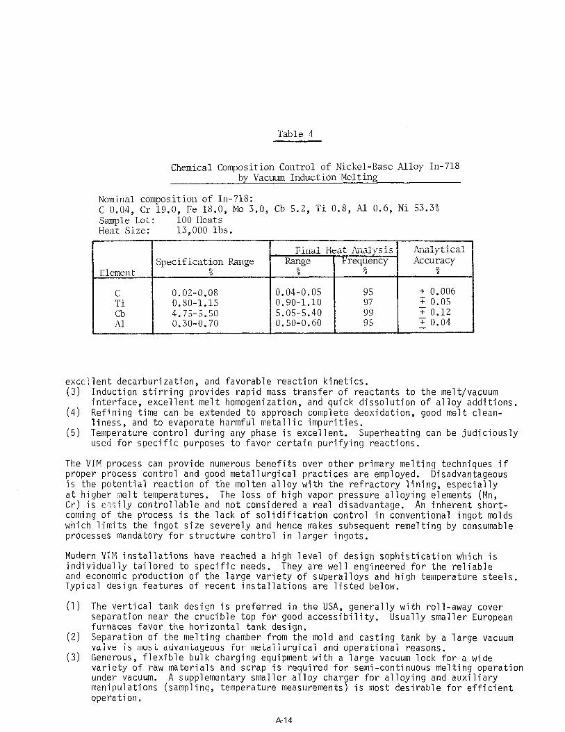
Table 4
Chemical Composition Control of Nickel-Base Alloy In-718 by Vacuum Induction Melting
Nominal composition of In-718: C 0.04, Cr 19.0, Fe 18.0, MO 3.0, Cb 5.2, Ti 0.8, Al 0.6, Ni 53.3% Sample Lot: 100 Heats Heat Size: 13,000 lbs.
excellent decarburization, and favorable reaction kinetics. (3) Induction stirring provides rapid mass transfer of reactants to the melt/vacuum
interface, excellent melt homogenization, and quick dissolution of alloy additions. (4) Refining time can be extended to approach complete deoxidation, good melt clean-
liness, and to evaporate harmful metallic impurities. can be judiciously (5) Temperature control during any phase is excellent. Superheating
used for specific purposes to favor certain purifying reactions.
The VIM process can provide numerous benefits over other primary melt proper process control and good metallurgical practices are employed. is the potential reaction of the molten alloy with the refractory lin
ing techniques if Disadvantageous
ing, especiaily at higher melt temperatures. The loss of high vapor pressure alloying elements (Mn, Cr) is e;:ilv controllable and not considered a real disadvantaqe. An inherent short- coming of the process is the lack of solidification control in conventional ingot molds which limits the ingot size severely and hence makes subsequent remelting by consumable processes mandatory for structure control in larger ingots.
Modern VIM installations have reached a high level of design sophistication which is individually tailored to specific needs. They are well engineered for the reliable and economic production of the large variety of superalloys and high temperature steels. Typical design features of recent installations are listed below.
(1) The vertical tank design is preferred in the USA, generally with roll-away cover separation near the crucible top for good accessibility. Usually smaller European furnaces favor the horizontal tank design.
(2) Separation of the melting chamber from the mold and casting tank by a large vacuum valve is most advantageous for metallurgical and operational reasons.
(3) Generous, flexible bulk charging equipment with a large vacuum lock for a wide variety of raw materials and scrap is required for semi-continuous melting operation under vacuum. A supplementary smaller alloy charger for alloying and auxiliary manipulations (sampling, temperature measurements) is most desirable for efficient operation.
A-14
(4) Design of the melting chamber for hot metal charging under vacuum, as has been practiced in Latrobe's Therm-I-Vat fur ace since 1964, may be considered if du- plexing operations are contemplated(20 7
(5) Introduction of the hot casting tundish'through a separate lock and positioning the molds on a turntable or on carts in a tunnel, or the use of a very well pre- heated traveling casting ladle in the mold tunnel are typical features modern VIM units.
(6) The use of advanced six-stage steam ejector pumping systems for operation at a pressure level of 5-20 x 10-3 Torr is common in today's large installations. Two parallel pumping systems are often employed for independent evacuation of the melting and mold chamber. Oil booster/diffusion and mechanical backup pumps are still used on smaller furnaces and for special applications requiring extremely low pressures (casting remelt stock).
(7) Higher specific induction power inputs from 60 or 180 cps static power supplies improve melt-down rates and productivity, but a very rigid furnace shell con- struction and good refractory practice are required.
(8) Auxiliary low frequency inductive stirring equipment is mandatory with 180 cps power supplies to provide good stirring in large crucibles.
(9) Refractory brick linings are a must for satisfactory lining life in large crucibles. Double brick linings have been successfully employed in Latrobe's 7.5, 15, and 30-ton crucibles since 1964. Refractories most widely used today are of the mag- nesia-spine1 type, high magnesia bonded with alumina, or of the high alumina variety. The use of crystallized lime for crucibles would be metallurgically most desirable.
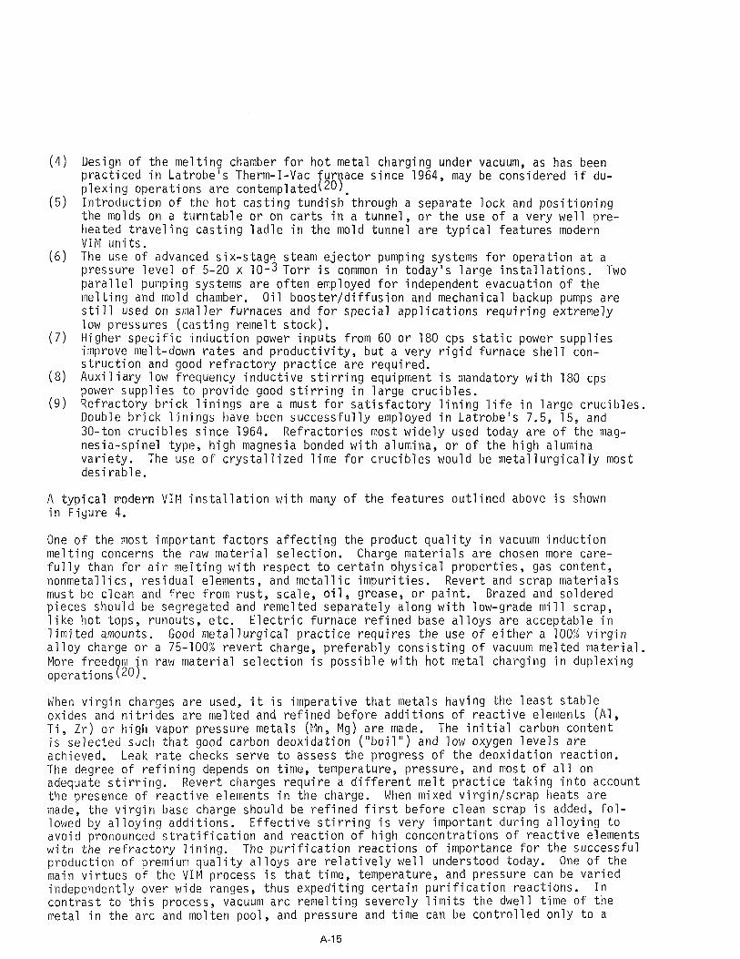
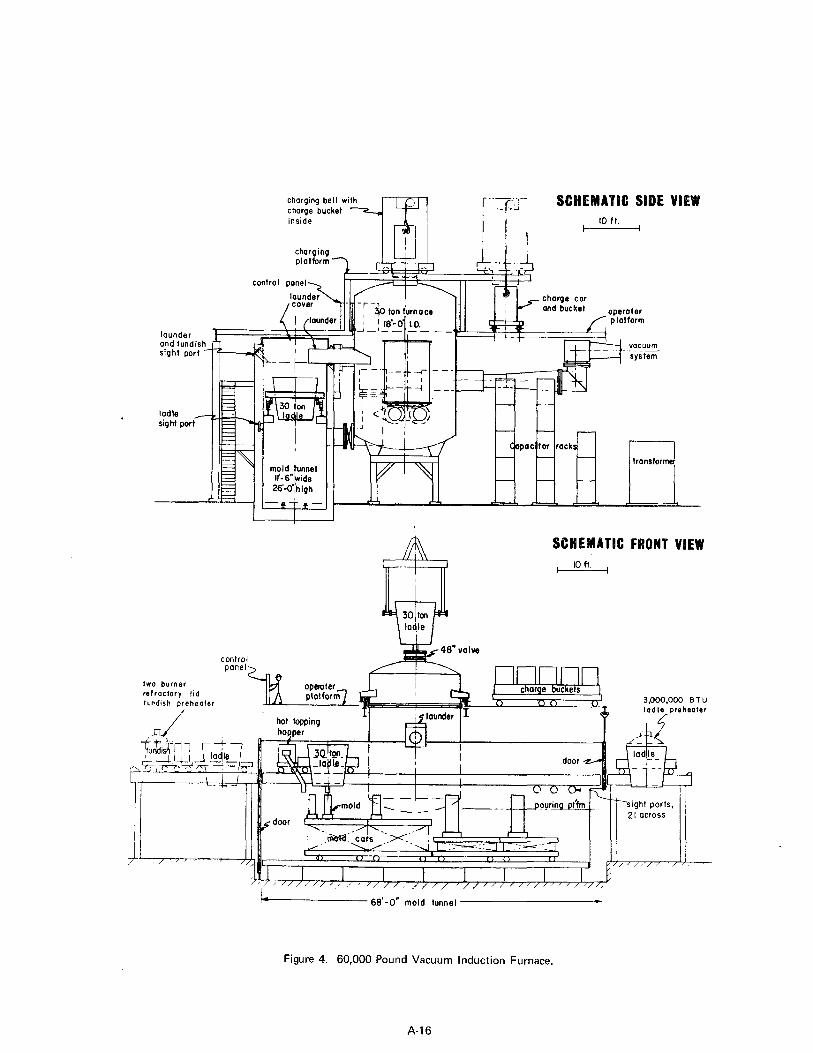
A typical modern VIM installation with many of the features outlined above is shown in Figure 4.
One of the most important factors affecting the product quality in vacuum induction melting concerns the raw material selection. Charge materials are chosen more care- fully than for air melting with respect to certain physical properties, gas content, nonmetallics, residual elements, and metallic impurities. Revert and scrap materials must be clean and fre'e from rust, scale, oil, grease, or paint. Brazed and soldered pieces should be segregated and remelted separately along with low-grade mill scrap, like hot tops, runouts, etc. Electric furnace refined base alloys are acceptable in limited amounts. Good metallurgical practice requires the use of either a 100% virgin alloy charge or a 75-100% revert charge, preferably consisting of vacuum melted material. More freed m in raw material selection is possible with hot metal charging in duplexing operations?20).
When virgin charges are used, it is imperative that metals having the least stable oxides and nitrides are melted and refined before additions of reactive elements (Al, Ti, Zr) or high vapor pressure metals (Mn, Mg) are made. The initial carbon content is selected such that good carbon deoxidation ("boil") and low oxygen levels are achieved. Leak rate checks serve to assess the progress of the deoxidation reaction. The degree of refining depends on time, temperature, pressure, and most of all on adequate stirring. Revert charges require a different melt practice taking into account the presence of reactive elements in the charge. When mixed virgin/scrap heats are made, the virgin base charge should be refined first before clean scrap is added, fol- lowed by alloying additions. Effective stirring is very important during alloying to avoid pronounced stratification and reaction of high concentrations of reactive elements with the refractory lining. The purification reactions of importance for the successful production of premium quality alloys are relatively well understood today. One of the main virtues of the VIM process is that time, temperature, and pressure can be varied independently over wide ranges, thus expediting certain purification reactions. In contrast to this process, vacuum arc remelting severely limits the dwell time of the metal in the arc and molten pool, and pressure and time can be controlled only to a
A-l 5
charging bell with charge bucket
-7-A
inside
charge car and bucket -.
ladle - sight port
1 mold tunnel
SC ATIC FRONT VIEW IO ft.
control panel
two burner refractory lid charge buckets lurdish preheater ?lli- ) ” 3,OOO.OOO BTU
/ L_A .--_.- “p Iadl>preheater
J
L 68’-0” mold tunnel
Figure 4. 60,000 Pound Vacuum Induction Furnace.
A-16
limited extent by adjusting the remelting parameters (see 4.2).
Impurities of primary concern are listed in Table 2. A general review of the puri- ficati n author 21 9 r
eactions and metal-efractory interactions was recently presented by the and Kinsm:!n et. al. published in 1969 a comprehensive survey of the physi-
cochemical'principles118). as follows:
Important basic refining aspects may be briefly summarized
Removal of Gases: Hydrogen: Nitrogen:
Easily reduced to very low levels of ~1 ppm. Removal more difficult; presence of nitride-forming elements (Cr, V, Ti, Al) reduces n-iltrogen activity, and surface active impurities (0,s) decrease- markedly removal rate.
Oxygen: Removal takes place through formation of CO. Most important deoxidation re- action. Thermodynamic equilibrium not attainable due to kinetic limitations and refractory interactions.
Removal of nonmetallic impurities: Phosphorous: Not removed. Sulfur: Desulfurization oossible but reactions are comolex and at verv low sulfur
Removal through impractical.
levels (<50 ppm)'often inefficient. LI
volatile compounds: SiS, CS, COS, SnS, - extremely
stable, insoluble sulfides: 1s must be closely controlled.
MgS, CaS, CeS2, LaS2 -
slags: CaOtCaF2, itations.
BaO, A1203, Mo03, CaC2 - practica
Removal through method, residua
practical
Removal through operational lim
method,
slow and
Evaporation of metallic impurities: Important refining reaction to remove harmful metallic impurities. Nickel-base alloys: Pb, Bi, Cu, Cd, Te, Se are efficiently removed; Sb, Sn, As are not
'removed. Iron-base alloys: Pb, Bi, Cu, Sn, Cd, Te, Se, As are removed. Interaction with refractory lining: Refractory crucible is never completely inert to the molten metal; this limits refining potential of the process. Important interactions are: (1) dissociation of refractory oxides (impurities) , lsupplying oxygen to the melt, and (2) reduction of oxides by car- bon resulting in incrleased refractory erosion and potential pickup of metallic refractory component.
Casting of the heats at low pressures is preferred to retain the optinum benefits from vacuum melting, but a partial inert gas pressure may be required for adequate retention of volatile alloying elements. Careful adjustment of the pouring temperature and at- tention to tundish design with dams and slag traps to hold back scum and refractory erosion products significantly contribute to product cleanliness. Using a large stopper rod tundish or ladle for bottom pouring allows control of the pouring rate and provides clean r metal in the molds. cult 721).
Hot topping of conventional ingots under vacuum is diffi- The use of special exothermic sleeves or tops made of highly insulating
inorganic fiber materials is generally satisfactory. Due to feeding and metallurgical problems, only relatively small ingots are cast for direct working. However, large slab ingots weighing up to 31,000 lbs. have been successfully produced in nickel-base alloys. A large proportion of VIM heats are cast into long consumable electrodes for subsequent vacuum arc or electroflux remelting, and into special molds for making cast- ing bar stock for remelting in small vacuum induction furnaces to produce vacuum in-
A-17
vestment castings. Hot topping of these products is not critical; however, the pouring conditions must be equally closely controlled to provide the required high quality standards. Vacuum induction melting represents the first manufacturing step in the important double vacuum melting process used for most advanced wrought and cast super- alloy products. It must be emphasized that final material properties depend not only on the secondary remelting process but are strongly influenced by the primary melting method as well.
The combination of VIM with electron beam hearth refining in a continuous melting unit has become known as the Airco-Temescal CRP 10T process. This development for the pro- duction of hig the literature 2 1T u
rity straight chromium stainless steel has been widely described in Although this combined process has an excellent potential for
superalloys, the present melting system is extremely complex and has severe flexibility limitations (see also 4.3).
3.4. Other Primary Melting Processes
Several other melting techniques for primary alloy making or reclamation of alloys from scrap are in industrial use, in pilot scale evaluations, or still in the laboratory de- velopment stage. As listed in Table 3, air induction melting, plasma arc melting, and non-consumable vacuum arc melting will be briefly discussed.
3.4.1. Air Induction Melting
Induction melting in many variations is widely used for investment casting of super- alloys and wrought alloy making. Air induction melting plus subsequent vacuum refining treatment in the same crucible has found limited use in the production of high temper- ature alloy ingots, electrodes, and casting stock. Principal advantages of this melting process are: efficient heat generation in the charge, easy operational control, ex- cellent melt homogenization, no carbon contamination. Traditionally, this furnace type has been considered primarily a remelting tool due to its limited refining capabilities associated with the difficulty of an effective slag treatment. The development of basic high purity refractories and particularly the application of crystallized lime as cr material has greatly expanded the metallurgical potential of the induction furnace (Y5jb
Oxygen and sulfur in iron-and nickel-base alloys are easily reduced to very low values l
of 15-30 ppm and 20-40 ppm, respectively, by melting in rammed crucibles of crystallized lime and using highly reactive basic slags. To take full advantage of the benefits im- parted by these low impurity levels on hot working and technological properties, any subsequent reoxidation during pouring must be strictly avoided. Theoretical and prac- tical sp cts of melting in lime crucibles have been discussed thoroughly in the liter- ature 24 . t e
Problems with air induction melting of superalloys concern primarily compositional con- trol of reactive elements which require a careful melting practice and elaborate de- oxidation techniques, and oxidation of reactive elements during pouring leading to very undesirable nonmetallic inclusions. Coreless induction furnaces of line or medium frequency lend themselves relatively easily to some degree of atmosphere control by melting under an inert gas blanket or better by designing a pressure tight cover over the crucible lid which permits melting and refining at reduced pressures. However, the problem of tapping the furnace in a protective inert atmosphere is not yet solved satisfactorily. One technique uses the Durville principle by attaching a launder to the furnace and tapping the melt t&l r a slag cover directly into cluster molds to pro- duce cleaner casting remelt stock Y e The Durville casting technique is capable minimize rapid oxidation during pouri;g, and this has been successfully adapted to
to
nickel-base superalloys cast into relatively small ingots.
le
A-18
3.4.2. Plasma Arc Melting
The plasma arc process was introduced in 1962 by Linde Divis'on of Union Carbide Cor- poration as a new concept for melting high quality materials 26 . The process is based I ) on the utilization of the gas shielded plasma arc which provides a clean, contamination- free source of intense heat at normal atmospheric pressure. Conventional hearth shapes or cylindrical vessels lined with refractories have been used in PAM and "inert arc" furnaces. Melting can be carried out slag-free or with thin, reactive slags to pro- mote certain specific purification reactions. Pure argon or mixtures with reactive gases provide the desii red furnace atmosphere and suitable conditions for a stable arc. The charge materials are melted rapidly by radiation and conduction. Alloy recoveries are high, melt le nliness to be excellent 27 . I; 5
is very good, and material properties have been reported Until very recently, the further development of this technique
has been stagnant in the USA but considerable efforts have taken place in Russia and Eastern Germany, where apparently some larger pilot units are in production. The po- tential use of plasma arc furnaces for primary alloy making, high alloy scrap reclamation, or for investment casting is promising if reliable protective tapping and teeming techniques are developed to retain full advantage of the high melt quality achieved. Combinations of other basic melting processes with supplementary plasma arc heating, such as induction melting + plasma torch, electron beam melting + plasma arc heating, electroslag melting with permanent plasma arc electrode, and the possible use of plasma arc burners for additional heating in vacuum induction and degassing/refining systems are merely mentioned here.
3.4.3. Nonconsumable Vacuum Arc Melting
Two nonconsumable electrode melting techniques, operating in vacuum or inert atmospheres, have been developed in recent years and found limited industrial applications, partic- ularly for reclamation of exotic and reactive metals scrap. However, the "Rotatrode" and "Durarc" processes are also of interest for reconsolidation of superalloy scrap and alloy making.
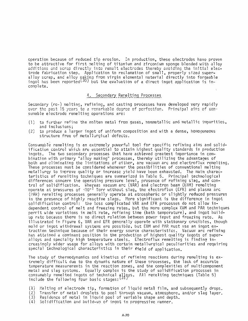
The "Rotatrode process" (28) developed by Schlienger Inc. for nonconsumable arc melting consists of a rOtati ng, water-cooled copper electrode which approaches the charge contained in the water-cooled copper crucible at an angle from 10-90" (F,igure 5). Be- cause this arc wheel electrode rotates at 100-250 rpm, the UC arc impinges on a given surface only for a very short time fraction, thus overheating is avoided and surface erosion minimized to very low values. Furnace atmosphere and pressure are closely controlled, ranging from high vacuum to positive pressure, depending upon the particular melting requirements. An elaborate feeding system for handling sponge ma- terial as well as fairly heavy scrap provides reliable and constant feeding of material to the melt. The adaptability of the Schlienger Rotatrode technique to various melting and casting systems ranges from skull melting to static casting and continuous ingot withdrawal. The basic Rotatrode design and the principal melting/casting approaches are schematically illlustrated in Figure 5. No crucible contamination takes place, but the crucible heat losses are extremely high and the development of a special refractory hearth is in progress.
The Rotatrode system lmay also be considered as a potential supplemental heat source in degassing/refining and vacuum induction melting technology.
The Westinghouse nonconsumable electrode is called "Durarc"(29). It does not rotate but incorporates in its water-cooled copper tip a cylindrical field coil that generates a magnetic field. Interaction of the arc and magnetic field forces the arc to rotate over the surface around the tip and thus prevents local overheating and damage to the tip. The electrode is hollow to allow passage of feed material and gases. Electrodes up to 16" diameter have been tested in vacuum and pressures up to 200 Torr by melting reactive metals and nickel alloys, using preferably the electrode positive mode of
A-19
operation because of reduced tip erosion. In production, these electrodes have proven to be attractive for first melting of titanium and zirconium sponge blended with alloy additions and scrap directly into remelt electrodes thereby avoiding the initial elec- trode fabrication step. Application to reclamation of small, properly sized super- alloy scrap, and alloy ak'ng from virgin elemental material directly into forgeable ingot has been reportedT30j but the evaluation of a direct ingot application is in- complete.
4. Secondary Remelting Processes
Secondary (re-) melting, refining, and casting processes have developed very rapidly over the past 15 years to a remarkable degree of perfection. Principal aims of con- sumable electrode remelting operations are:
(1) to further refine the molten metal from gases, nonmetallic and metallic impurities, and inclusions;
(2) to produce a larger ingot of uniform composition and with a dense, homogeneous structure free of metallurgical defects.
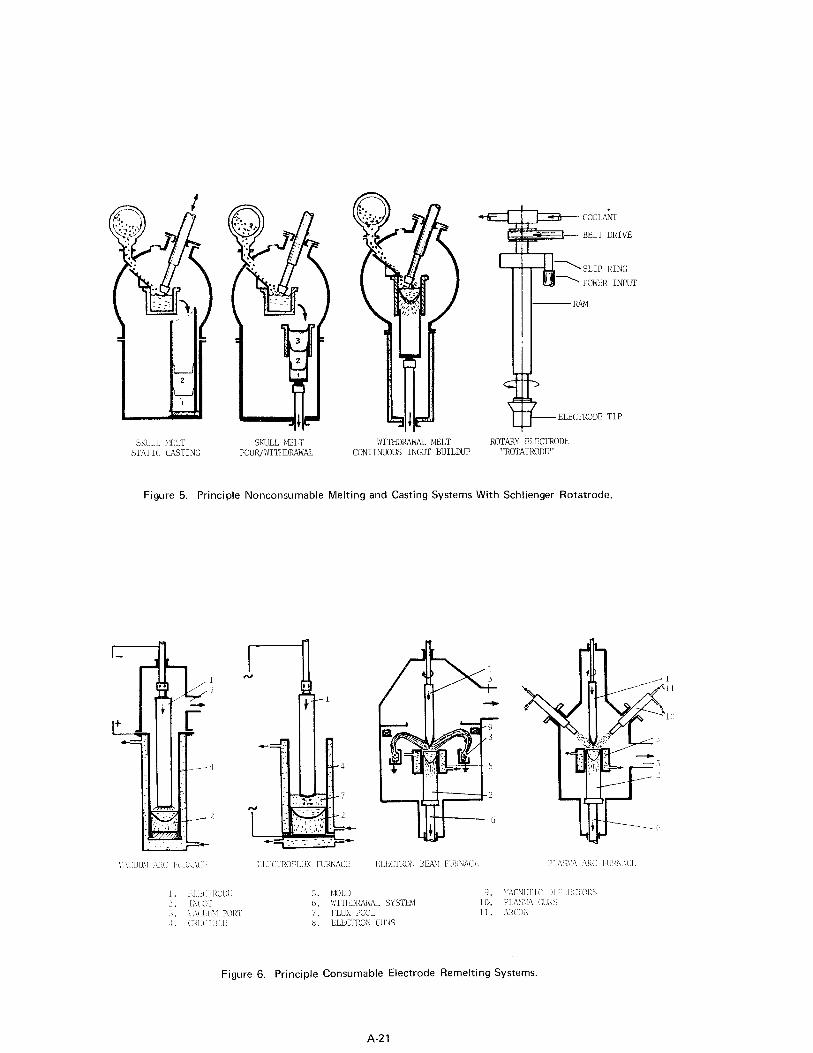
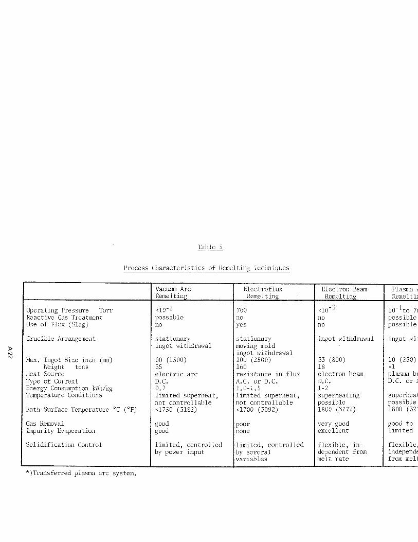
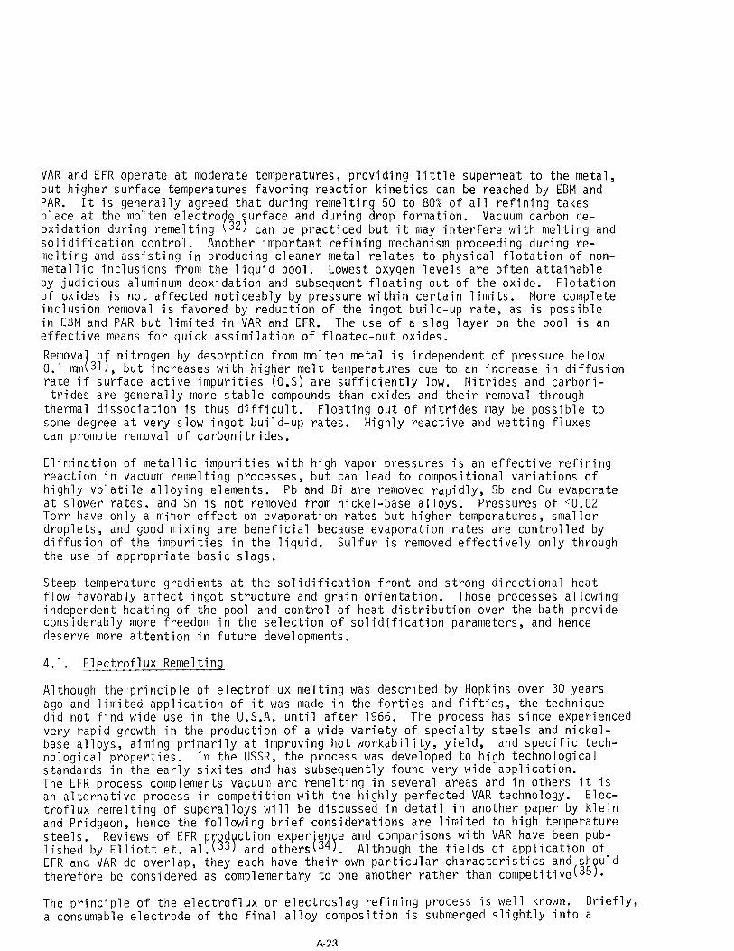
Consumable remelting is an extremely powerful tool for specific refining aims and solid- ification control which are essential to attain highest quality standards in production ingots. The two secondary processes that have achieved greatest importance in com- bination with primary "alloy making" processes, thereby utilizing the advantages of both and eliminating the limitations of either, are vacuum arc and electroflux remelting. These processes must be considered whenever the possibilities of conventional melting metallurgy to improve quality or increase yield have been exhausted. The main charac- teristics of remelting techniques are summarized in Table 5. Principal technological differences concern the operating pressure level, presence of refining slag, and con- trol of solidification. Whereas vacuum arc (VAR) and electron beam (EBM) remelting operate at pressures of <lo-' Torr without slag, the electroflux (EFR) and plasma arc (PAR) remelting processes generally operate at atmospheric or slightly reduced pressures in the presence of highly reactive slags. More significant is the difference in ingot solidification control: the less complicated VAR and EFR processes do not allow in- dependent control of melt and freezing rates, but the more complex EBM and PAR techniques permit wide variations in melt rate, refining time (bath temperature), and ingot build- up rate because there is no direct relation between power input and freezing rate. As illustrated in Figure 6, VAR and EFR generally operate with stationary crucibles, though mold or ingot withdrawal systems are possible, but EBM and PAR must use an ingot ex- traction technique because of their energy source characteristics. Vacuum arc refining has attained a dominant position in the production of highest quality ingots of super- alloys and specialty high temperature steels. Electroflux remelting is finding in- creasingly wider usage for alloys with certain metallurgical peculiarities and requiring special teChnOlOgiCa1 CharaCteriStiCi in their field of application.
The study of thermodynamics and kinetics of refining reactions during remelting is ex- tremely difficult due to the dynamic nature of these processes, the lack of accurate temperature measurements in the reaction zones, and the complexities of multicomponent metal and slag systems. Equally complex is the study of solidification processes in consumably remelted ingots of technical pWjys* All remelting techniques (Table 5) include the following four basic stages:
(1) Melting of electrode tip, formation of liquid metal film, and subsequently drops. ('2) Transfer of metal droplets to pool through vacuum, atmosphere, and/or slag layer. (3) Residence of metal in liquid pool of variable shape and depth. (4) Solidification and build-up of ingot in progressive manner.
A-20
SKULL hU.LT SMTIC CASTING
SKULL MELT POLlR/WITI IDRMU
c&B-- coo1irI >-- BELT DRIVE
SLIP RING
POb\XR INPUT
. ELECTRODE TlP
WITHDIWWAL bIELT ROTARY ELECTRODE
CONTINUOUS INGOT BUILDUP “ROTATRODE”
Figure 5. Principle Nonconsumable Melting and Casting Systems With Schlienger Rotatrode.
r c t : 4
Ii d
:. ._ * 2
, , -- : ,,
C,‘G,
;r”-
I. I l.l.(: I l!O!)l. 5. ?WLD I:“Lo’i b IiITl LURAhX SYSTUI ic. l’l./\s:t\ (;il:ii;
Figure 6. Principle Consumable Electrode Remelting Systems.
A-21
Till) 1c i;
Process Cllaracteristics of Remelting Teclhyues _
Crucible Arrangemext ingot withdrawal ingot withdrawal
Max. Ingot Size inch (mm) Weight tons
I leat Source Tyile of Current Energy Consumption Wh/kg Temperature Conditions
i3ath Surface Temperature ‘C (OF)
electric arc
not controllable
resistance in flux A.C. or D.C.
not controllable
electron beam D.C. or A.C.
Gas Removal Impurity Evaporation
Solidification Control limited, controlled
from melt rate
*) Transferred piasma arc sys tern.
VAR and EFR operate at moderate temperatures, providing little superheat to the metal, but higher surface temperatures favoring reaction kinetics can be reached by EBM and PAR. It is generally agreed that during remelting 50 to 80% of all refining takes place at the molten electro e oxidation during remelting 32 f s
urface and during drop formation. Vacuum carbon de- can be practiced but it may interfere with melting and
solidification control. Another important refining mechanism proceeding during re- melting and assisting in producing cleaner metal relates to physical flotation of non- metallic inclusions from the liquid pool. Lowest oxygen levels are often attainable by judicious aluminum deoxidation and subsequent floating out of the oxide. Flotation of oxides is not affected noticeably by pressure within certain limits. More complete inclusion removal is favored by reduction of the ingot build-up rate, as is possible in E3M and PAR but limited in VAR and EFR. The use of a slag layer on the pool is an effective means for quick assimilation of floated-out oxides.
Remova o nitrogen by'desorption from molten metal is independent of pressure below 0.1 mm 31 1 f but incre,ases with higher melt temperatures due to an increase in diffusion rate if subface active impurities (0,s) are sufficiently low. Nitrides and carboni-
trides are generally more stable compounds than oxides and their removal through thermal dissociation is thus difficult. Floating out of nitrides may be possible to some degree at very slow ingot build-up rates. Highly reactive and wetting fluxes can promote removal of carbonitrides.
Elimination of metallic impurities with high vapor pressures is an effective refining reaction in vacuum remelting processes, but can lead to compositional variations of highly volatile alloying elements. Pb and Bi are removed rapidly, Sb and Cu evaporate at slower rates, and :Sn is not removed from nickel-base alloys. Pressures of CO.02 Torr have only a mino'r effect on evaporation rates but higher temperatures, smaller droplets, and good mixing are beneficial because evaporation rates are controlled by diffusion of the impurities in the liquid. Sulfur is removed effectively only through the use of appropriate basic slags.
Steep temperature graldients at the solidification front and strong directional heat flow favorably affect ingot structure and grain orientation. Those processes allowing independent heating o,f the pool and control of heat distribution over the bath provide considerably more freedom in the selection of solidification parameters, and hence deserve more attention in future developments.
4.1. Electroflux Remelting
Although the principle of electroflux melting was described by Hopkins over 30 years ago and limited applilcation of it was made in the forties and fifties, the technique did not find wide use in the U.S.A. until after 1966. The process has since experienced very rapid growth in the production of a wide variety of specialty steels and nickel- base alloys, aiming primarily at improving hot workability, yield, and specific tech- nological properties. In the USSR, the process was developed to high technological standards in the earl:y sixites and has subsequently found very wide application. The EFR process compllements vacuum arc remelting in several areas and in others it is an alternative procesms in competition with the highly perfected VAR technology. Elec- troflux remelting of 'superalloys will be discussed in detail in another paper by Klein and Pridgeon, hence the following brief considerations are limited to high temperature steels. Reviews of EFR prod ction exper'en e lished by Elliott et. al.( 3 and others 34 . 3r I F
and comparisons with VAR have been pub- Although the fields of application of
EFR and VAR do overlap, they each have their own particular characteristics and sh uld therefore be considerled as complementary to one another rather than competitive( 35?.
The principle of the lelectroflux or electroslag refining process is well known. Briefly, a consumable electrode of the final alloy composition is submerged slightly into a
A-23
highly reactive, superheated liquid flux bath at temperatures of 1600-1900°C (2912- 3542"F), which is resistance heated by the electric current passing between electrode and molten metal pool. The electrode tip melts, droplets form and fall through the refining flux into the liquid metal pool, where progressive solidification takes place thus building up an ingot. Refining reaction rates and equilibrium conditions are greatly favored by th 3000 cm2/kg (212 in. 5
superheated flux pool and the large interfacial areas of up to /lb.)
(see 4.0). created at the various reaction sites mentioned previously
Intensive exchange reactions between metal and flux are likely to take place at the electrode tip where liquid metal films of 50 to 2500ym thickness form be- fore droplets of 1-15 mm diameter are detached and fall through the reactive flux bath. The dwell time of the droplets may vary from 0.1 to 10 seconds, depending upon flux pool depth, composition, and type of current used. The interface between metal pool and flux appears to be of less significance except for certain deoxidation reactions and the absorption of floated out inclusions. Although the liquid flux basically pro- tects the molten metal from direct interaction with the furnace atmosphere, the gas phase present must be taken into account along with electrode and flux compositions, and thermal conditions when the various remelting parameters are being considered. Because liquid slags are largely dissociated in ions, the electric current is not only the heating source but, depending on current polarity or frequency, voltage, and current density, it also affects metaklag reactions which is particularly evident in certain compositional changes and oxide inclusion content. Iron-base alloys are especially prone to electrochemical interactions because the variable valency of iron ions and associated oxidation-reduction reactions enhance oxygen transfer between the phases. An additional factor is the high activity of Fe0 in claciumfluoride-based fluxes. Continuous addition of strong deoxidizers is not always possible because pickup by the metal may be unacceptable and cleanliness improvements are often inconsistent. Lowest inclusion contents are achieved by a careful balance of the flux composition with the electrode material and selecting the proper type of current. An oxygen-free furnace atmosphere minizes inclusion content and compositional changes in the remelted material. Resarding the current type,A.C. provides the best composition control and microclean- liness, followed by D.C. reversed polarity. D.C. straight polarity produces the poorest microcleanliness in production size ingots of iron-base alloys.
The electroflux remelting process has a number of features which are attractive to wrought alloy producers but also a few shortcomings. Chemistry control is a problem attributable to mildly oxidizing conditions of the liquid flux and it is most pro- nounced with alloys containing reactive elements. This may lead to unacceptable com- positional variations and gradients along the ingot length unless special precautions are employed. Complete nitrogen retention is of advantage with nitrogen-alloyed high temperature chromium and Cr-Ni steels. The formation of a thin flux layer between crucible and ingot produces smooth and dense ingot skins which generally enhance initial hot workability. Production of shaped ingots and slabs with high aspect ratios is of considerable importance for some alloys and applications. The process permits greater tolerance in the selection of remelting parameters owing to the favorable thermal effects of the flux bath by providing uniform heat distribution over the pool and reducing thermal gradients. The larger thermalmass minimizes the influence of power fluctuations, melt control instabilities and unsteady electrode feed response on metal pool and solidification disturbances. The high degree of melt control sensitivity required in VAR is not needed in EFR which can operate successfully with a relatively simple voltage control system. Flux technology, compatibility with various alloys, and compositional changes need close attention and pose some control problems. A critical phase of the electroflux operation is the cold start-up procedure which requires special practices and skill to minimize bottom end ingot defects. these difficulties. The final phase of hot topp in VAR providing consistently sound ingot tops.
Liquid flux starting.largely eliminates ing is simple and more reliab le than
A-24
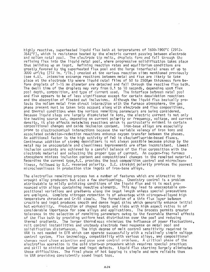
All recent EFR installations operate with A.C. power, using saturable reactor control of the current and continuous voltage adjustment. Current programming in conjunction with load cell weighing systems has been developed by Consarc Corp. and is considered standard in today's furnace design. A modern 20" diameter EFR furnace featuring ad- vanced control systems and coaxial current feeding to minimize power losses and un- desirable magnetic stray fields is illustrated in Figure 7. A separate flux melting unit at the base of the two static crucible stations provides the liquid flux for quick and reliable start-up of the melting operation. The middle station can be used for an ingot withdrawal setup with electrode changes carried out by the two masts nor- mally used on the two stations.
4.2. Vacuum Arc Remelting
The VAR process was introduced during the mid-fifties to improve ingot sizes and quality of high performance coimplex alloys. It has since grown rapidly and found wide accept- ance in the USA for superalloys and specialty steels. VAR is the most important and dominant remelting process in the production of double vacuum melted advanced super- alloys which must meet extremely stringent specifications for their use in rotating engine parts and many lother critical applications.
Heat is generated in VAR at low pressures by the application of a low voltage, high current electric arc bletween the surface of molten metal and a consumable electrode of the final alloy comiposition. The temperature of the molten film at the electrode tip exceeds only slightly the liquidus temperature of the alloy before the droplets pass through the extremely hot arc plasma and collect in the metal pool. However, the pool does not acquire Imuch superheat even at high current densities because of consider- able heat losses by radiation, evaporation, convection, and conduction to the water- cooled inert copper mold. No crucible reactions take place and evaporation losses of some alloying elemelnts are readily controllable. A large number of widely different alloys of almost any composition are remelted and improved by the VAR process.
The solidification rate depends on the melt rate, which in turn is determined by the power input, thus the (dwell time of the metal in the liquid state is limited. In- ability to use refining slags, problems of alloying, arc control sensitivity, and some- times poor ingot surfalces are considered principal process disadvantages. Good hydrogen and acceptable nitrogen removal, carbon deoxidation, and minimizing as well as dispersing of remaining inclusions result in significant property improvements, particularly in regard to ductility, impact, and fatigue properties.
The principle of vacuum arc remelting is well knoidnand needs no description here. The basic furnace design applies to small experimental units as well as to large instal- lations which ha e een standardized to some degree. VAR furnaces are 36 : Y P
Typical design features of modern
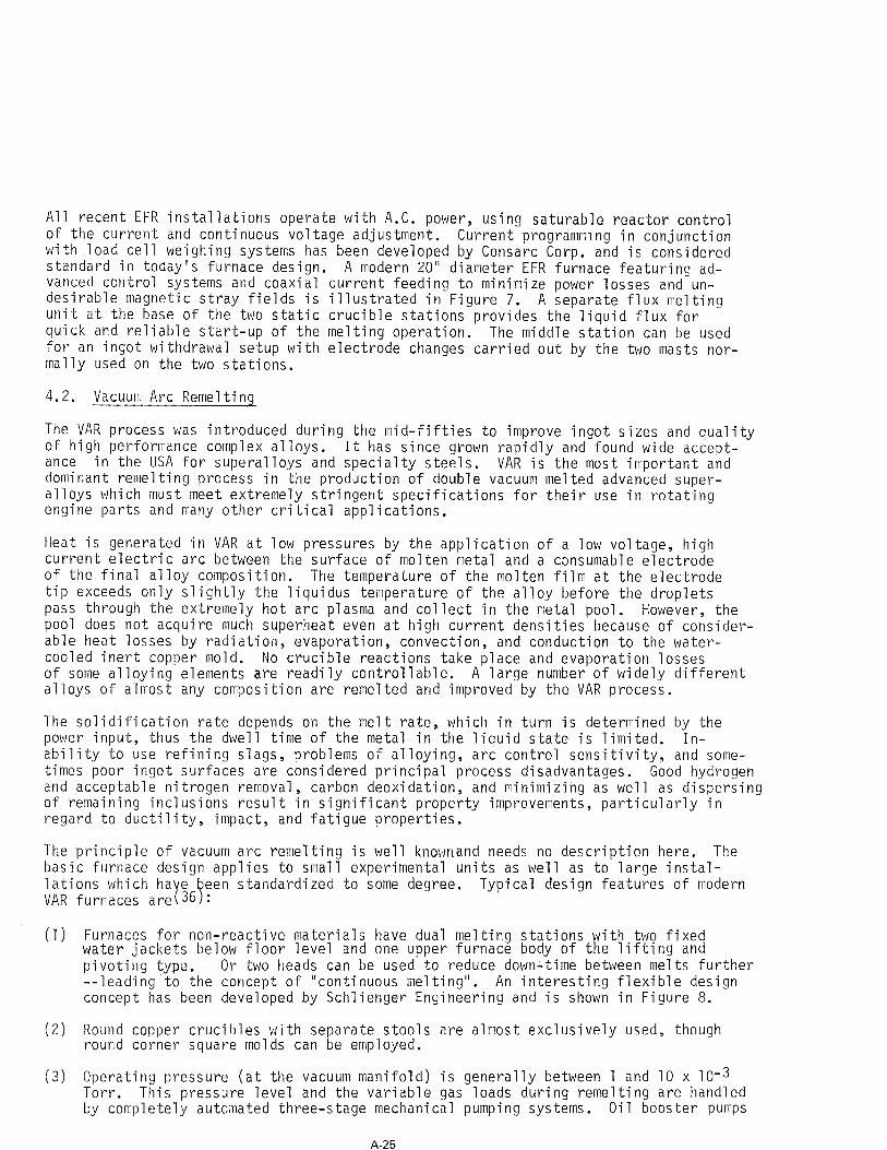
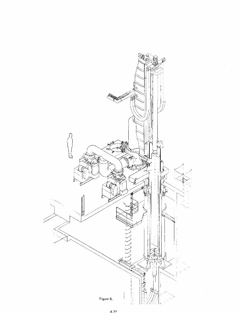
(1) Furnaces for non-reactive materials have dual melting stations with two fixed water jackets below floor level and one upper furnace body of the lifting and pivoting type. Or two heads can be used to reduce down-time between melts further --leading to the concept of "continuous melting". An interesting flexible design concept has been developed by Schlienger Engineering and is shown in Figure 8.
(2) Round copper crucibles with separate stools are almost exclusively used, though round corner square molds can be employed.
(3) Operating pressure (at the vacuum manifold) is generally between 1 and 10 x 10m3 Torr. This pressure level and the variable gas loads during remelting are handled by completely autcmated three-stage mechanical pumping systems. Oil booster pumps
A-25
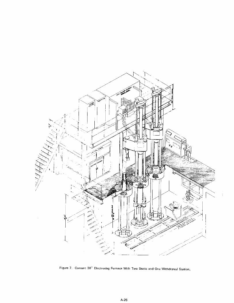
Figure 7. Consarc 20” Electroslag Furnace With Two Static and One Withdrawal Station.
A-26
(4)
(5)
(6)
(7)
(8)
(9)
(10)
may be employed in parallel with large Roots blowers.
Careful design of the ,entire water-cooling system is important, especially the crucible caoling circuit. Advisa,ble is the use of hig,h speed recirculation pumps and water guidses to assure adequate flow velocity at the crucible surface to avoid water stagnation and detrimental stea,m bubble formation.
Advanced D.C. power supplies are exclusively used, providing good cwrren,t stability, fast response to load changes, and excellent reliability. Smooth current control is achieved by saturable reactors in the primary circuit and constant current out- put at operating voltages of 24-35V is provided by a closed loop control system which keeps current fluctuations well below 2 2%. SCR units, despite certain advantages, have so far found only limited application in VAR.
Bus bar layout and current supply arrangement to the furnace are critical to min- imize undesirable stray magnetic fields leading to serious metallurgical pr&lems. The coaxial current supply concept and symmetrical current leads are carefully designed into modern installations.
Three electrode drive systems are in use and considered equivalent regarding re- sponsiveness, accuracy, and reliability: electro-mechanical double differential gear systems and electro-hydraulic motors drive ball screws, whereas hydraulic cylinders utilize the stinger rod as piston.
Arc gap or electrode position controls have received extensive attention because homogeneity and quality of the ingots depend profoundly on the sensitivity and reliability of the arc control system have been discussed in the literature (36T
he pros and cons of the various methods . It is recommended to 'have at least
two systems available when a wide variety of different alloys and steels are re- melted in one furnace.
Installation of magnetic coils for arc stabilization and stirring is relatively common but they are often improperly used. The principal function is twofold: (a) elimination of undesirable, uncontrolled pool rotation caused by stray mag- netic fields (see 6 above), and (b) intentional stirring and agitation of the pool for refining of the grain structure and improving the heat distribution in the arc zone.
Extensive indicating and recording instrumentation, and pool viewing systems are indispensible in modern plants. Continuous electrodeweighing by load cells, allowing accurate control of the burn-off rate and consistent hot topping, greatly improve:reliability and reproducibility of the remelting operation.
Superalloy and steel consumable electrodes with a diameterzlength ratio of up to 1:12 are usually cast into slightly tapered molds. The electrode diameter for a given ingot size is a compromise based on technological and economic considerations, such as degree of purification, primary melting process, maximum ingot weight. The primary melting process for the electrode stock is of critical importance because it decisively in- fluences final cleanliness, ingot quality, and material properties. Minor adjustment of the electrode chemistry to anticipated alloy changes is advisable to remain within the tight compostition tolerances usually specified. Some surface preparation of the cast electrodes is required which, depending on material and final quality standards, may consist of shot blasting, wire brushing,grinding, or machining. Trimming of the top sink (and bottom end) is generally necessary.
Vacuum arc remelting programs in general consist of three distinct phases: (1) initial
A-28
high power level to offset the chill effect from the stool, (2)
subse uently reduced to constant power over major portion of the ingot, and finally s 3) gradual reduction
of power during the hot topping cycle to minimize top end shrinkage cavities. A major portion of phase (2) may consist of a slow tapering off from the high level to the constant burn-off power level. The choice of the melting current is a compromise between productivity and metallurgical requirements. Complex superalloys and high temperature steels are melted at relatively low power input to maintain a shallow pool and minimize segregation effects. Because of the constant voltage in VAR, the melt rate is proportional to the current and can be expressed as weight per kiloampere- minute. Typical specific burn-off rates for nickel and iron base alloys are in the range of 1.2-1.6 lb/kA-min. schedule.
These factors are also useful to calculate the hot topping
Effective removal of gases (HZ, N2, CO) and volatile impurities depends on pressure and temperature in the arc zone and on residence time in the liquid state. Electrode/ ingot geometry is another factor since in general refining conditions improve with larger ingots. A considerable pressure gradient exists between the point of pressure measurement in the furnace top and the arc zone which may amount to several Torr. Manganese is the only alloying element lost in significant amounts by volatilization. Larger ingots and lower melt rates increase manganese losses because of longer dwell times in the molten condition. Sulfur and phosphorus are not removed during VAR.
One of the main purposes of VAR is to improve cleanliness, which is achieved by chemical and physical processes. Less stable oxides and nitrides may be dissociated or reduced by carbon at the temperatures and pressures existing in the arc region. However, since most harmful inclusions present are very stable (A1203, TiCN, spinels), the more im- portant process is physical flotation and dispersion of inclusions. The arc forces disperse metal droplets and gross inclusions creating large surface areas for refining reactions to proceed rapidly and producing a fine distribution of remaining much smaller inclusions. Cleanliness improvements
P!H ,?383 s ciated property benefits have been ex-
tensively documented in the literature . For certain steels and alloys requiring extremely good microcleanliness, the VAR process has proven to be superior and more reliable than EFR, especially when impact and fatigue properties are critical. Im- provements of properties in the transverse direction are, however, not only affected by the excellent cleanliness, but also by the superior ingot structure.
The very steep thermal gradients existing in the slightly superheated pool (30-50°C) contained in the water-cooled copper crucible favor columnar solidification in the ingot. Columnar growth is promoted by high melting temperatures and high degree of purity, i.e. absence of nucleants. Hot workability may be adversely affected by large grains because of potentially higher concentrations of embrittling residual impurities in the grain boundaries. Grain refining by use of cyclic magnetic stirring can im- prove this condition.
Consumable melting "freckle" segregates w, 34
pro uce two types of segregation: "tree rings" and spot or . "Tree ring" segregation, manifested by a series of con-
centric bands and accentuated in billets and bars, is caused by sudden changes in the solidification process due to power input fluctuations or cyclic variations in heat flow to the crucible. No significant chemical differences have been detected between the rings since the effect is mainly caused by a difference in grain size and mechanical properties are unaffected. A serious defect sometimes encountered in alloy steels and superalloys is known as "spot" or "freckle" segregation, which can show up in different forms and distributions. Freckles represent areas of interdendritic segregation having high concentrations of certain elements with high segregation coefficients. They are most prevalent in mid-radius and subsurface zones. Several explatlations and mechanism of freckle formation have been proposed, some purely speculative and others based on
A-29
model experiments, (40,41) but the actual mechanism remains clouded. Generally, two types of freckles may be distinguished: (1) higher d ensity freckles formed by heavy alloying elements which tend to sink to the bottom of the mushy zone of the pool (e.g. in I-718), and (2) a lower density variety composed predominantly of lighter alloying elements and tending to rise through the liquidus-solidus region (e.g. in Waspaloy). Pool movements can enhance the flow of interdendritic liquid and hence accentuate spot segregation effects (radial segregation), and uncontrolled motion of the pool is known to produce freckle colonies in circular arrangements.
4.3. Electron Beam Melting of Consumable Electrodes
The concept of electron beam melting (EBM) was first used by Pirani in 1905 but con- siderable research efforts were required to develop it for industrial melting, which started about 1954 when Temescal began to construct electron beam melting systems.
;;;:,pv ering work led in 1961 to the production of 20" diameter ingots of super- . In Europe, Heraeus has been .an important manufacturer of electron beam
equipment and the Institute M. Ardenne in East Germany advanced this technology to high standards. Electron beam melting as a primary melting process for superalloys has not found the acceptance as initially predicted except in the field of refractory metals and alloys. Little information on EB remelting of superalloys and steels appeared in the U. S. literature but significant activity has been reported in Germany and the USSR, especially in the field of bearing steels. Additional quality improvements over other special melting processes have been marginal. Economies are still against the process which may be overcome with larger furnaces in the 3-10 megawatt range and future application of EBM could grow with the increasingly tougher impurity specific- ations imposed on advanced superalloys. Electron beam casting appears to have good growth potential and should find more attention in the future.
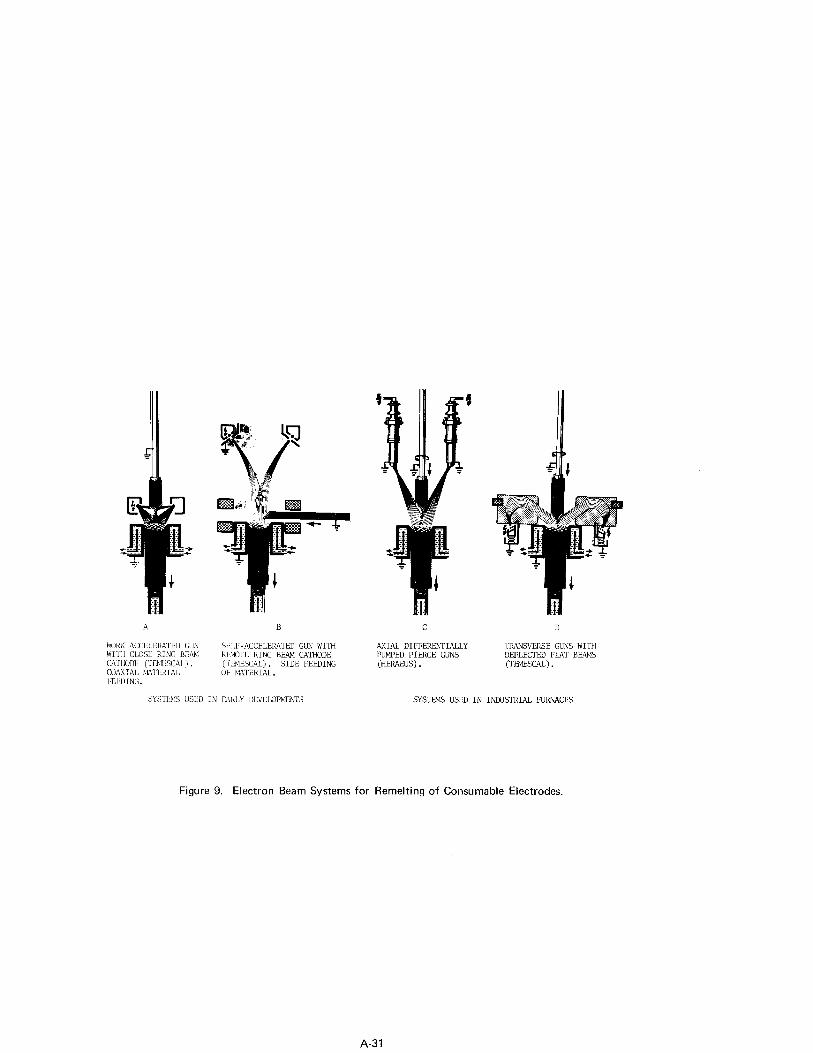
Electron beam melting utilizes the energy of highly accelerated electrons to produce thermal energy generated in the material itself for melting and refining. The transfer of kinetic energy of the electrons to the material on impact leads to local temperature rise and melting. Four principle types of electron beam guns nd the basic geometry of remeltin systems are illustrated schematically in Figure 9 43 ated" guns 9
7 1 In "work-acceler- Type A) the voltage for accelerating the electrons is applied between the
electron-emitting cathode and the material to be melted. The close and remote annular cathodes (Figure 9B) are sensitive and operationally not too reliable. Therefore, these guns have been replaced by more efficient and more trouble-free "self-accelerated" guns where the voltage is applied between the cathode and an auxiliary anode arranged in relatively short distance from it, effect (Figure 9C,D).
in order to achieve the desired beam-forming The potential between this gun-type and material to be melted
can thus be kept low. The complicated Pierce-type guns (Heraeus, Figure 9C) are capable of beam powers up to 200 kW, though the single, differentially pumped gun used 'n Ardenne's largest EB remelting furnace for specialty steels is rated at 1700 kW 44 . 1 ) Another type of gun developed by Temescal and used in multi-gun systems is the trans- verse-field linear gun (Figure 9D), which is self-accelerating, simple, rugged, and hence particularly suited for metallurgical applications. Power supplies are conven- tional three-phase, full-wave rectified D.C. systems, preferably in modular construc- tion with multiple parallel units, components (transformers, reactors,
Since voltages of 5-20 kV are used, the voltage capacitors) must be generously designed and fab-
ricated to very rigid specifications to provide satisfactory reliability in continuous service.
The vacuum system for EBM furnaces must be designed very carefully and have adequate capacity to remove non-condensable gases at such rates that no appreciable pressure rise occurs in the tank. Localized higher pressures can cause electrical instability and breakdown. Large diffusion pumps must handle large volumes of gas at pressures of ~5 x 10⁻⁴ Torr. Sufficient backing capacity must be provided to maintain low fore-
A-30
A
WORt-ACCtLkRATkD GUN WI’171 CLOSL: RING BIX-I CATIKXK ~lmlsCAL) . (:OhkIAL M’iltRIAL
B
SEl.F-ACCELERATED GUN WITH IUMJTE RING BEAM CATHODE (TLmSCZL) . SIDE FEEDING OF MATERIAL.
SYSTLK USkD IN FAIILY D~VELQPMENTS
C
AXIAL DIFFEREhTIALLY PUMPED PIERCE GUNS (HERAEUS) .
D
TRANSVERSE GUNS WITH DEFLECTED FLAT BEAMS (TIYIEXAL) .
SYSTFM.5 USED IN INDUSTRIAL FURNACES
Figure 9. Electron Beam Systems for Remelting of Consumable Electrodes.
A-31
pressure for diffusion pumps to minimize backstreaming.
As indicated in Figure 9, feed material can be introduced into the melt chamber either as an electrode (ingot) from the top or as bar (ingot),powder, pellets, or scrap through the side feed lock, The feed material is fused by the electron bombardment and drips into the water-cooled ingot mold forming a molten pool and subsequently an ingot which is withdrawn from the mold so that the pool level remains constant. Con- trol of these furnaces requires considerable operator skill because of rapidly changing melting conditions. Volatile impurities, interstitial gases, gaseous products from purification reactions evolve often quite violently requiring quick reaction by the operator in adjusting the melt controls. The use of vacuum processed melt stock is therefore much preferred.
EB melting and refining permits one to approach the theoretical limit of impurity re- moval much closer than is attainable with other vacuum melting processes. In VAR the time available for the refining and purifying reactions is limited because a minimum melt rate must be maintained to keep the pool completely liquid over the whole surface and additionally the temperature tolerance is restricted which reduces the favorable temperature ranges for the completion of reactions. These limitations are virtually
Agbsent in EBM and the much lower partial pressures for the impurities emerging from the melt favor their removal. The specific energy required to melt can be controlled independently of the energy needed for refining. In contrast to VAR, very slow melt rates are possible providing longer residence time for maximum purification. The melt can be held at any desired temperature, and superheating can be utilized to achieve reactions otherwise not possible or extremely slow. This specific feature of control- lability and the following purification processes are of primary interest in EBM:
(1) Vaporization of suboxides, if the oxide has a higher vapor pressure than the melt. (2) Evolution and removal of interstitial gases (H,N,O) is essentially determined by
the residence time and in turn controlled by the melt rate. (3) C-O reaction and metal-oxygen reactions proceed rapidly to low equilibrium values. (4) Vaporization of metallic impurities takes place if the ratio of impurity to solvent
content in the vapor phase is much greater than in the melt. (5) Floating of non-melting insoluble compounds and inert inclusion which are neither
decomposed nor reduced. (6) Composition segregation, i.e. zone solidification effects exist because of strong
directional solidification.
Mass transport in the liquid by convective flow and diffusion is the rate-determining factor. Material transfer will mainly occur at the molten surface of the feed stock. Transport processes in the space above the melt are usually not rate-determining in EBM. For condensable vapors the cold chamber walls act as condensation pump of very high pumping speed and for permanent gases the nominal pumping speed of the system is the controlling factor. While evaporation of impurities is one of the basic EB refining functions, it is at the same time a leading cause of difficulties in maintaining alloy compositions when elements with diverse vapor pressures are present. However, presently it is not limitations in the extent of purification, but economic factors which hinder the growth of EBM.
Electron beam remelting furnaces have excellent flexibility in regard to shape and size of feed stock and cross-sectional configuration of the cast product(45). Continuous casting of circular, square, or rectangular ingots is practiced in the large electron beam-cold hearth refining installation (18 EB guns each rated at 150 kW) at Airco- Temescal which is operated in conjunction with vacuum induction melting and holding furnaces for a steady supply of liquid metal at the rate of 5 tons/hour(22). Plasma- electron beam melting operating with a hollow cathode at somewhat higher pr 2 'res has been described in the literature and may soon debut as a commercial process 7-3 r .
A-32
4.4. Plasma Arc Remelting
Earlier activities in utilizing plasma burners for primary melting as described in section 3.4.2. have been recently supplanted by development efforts in plasma arc re- melting (PAR) for the production of ingots of a large variety of metals and alloys. ;;t;;em;;;R
7 e jj mats, it appears now that furnaces of respectable size are in operation
and pilot work in the USA is also progressing rapidly which may lead to industrial introduction of plasma arc remelting within the next five years. It is, however, not yet clear where this remelting technique may fit in the broad spectrum of existing melting and refining systems, except for a few very specific applications.
The basic design of plasma burners is simple and the two basic types are illustrated schematically in Figure 10. A D.C. arc is struck between the tungsten cathode and the water-cooled copper anode shaped into a nozzle. The gas flow carries the arc through the nozzle opening, forming a freely burning plasma flame, which represents the in- direct or non-transferred plasma arc burner. It is also possible to use the molten pool itself as anode, (Figure 1OU).
as is the case in the direct or transferred plasma arc system To facilitate arc initiation in direct plasma arc burners, a modification
of the D.C. power circuit is employed as indicated in Figure 1OC. The actual plasma flame is generated by interaction of the working gas or gas mixture with electrons emitted from the cathode and accelerated in the electric field of the arc which results in dissociation and/or ionization of the gas. The equilibrium between neutral and ionized gas particles and electrons is a function of the gas, the temperature, and the energy density which has a magnitude of about lo6 A/cm2 in the plasma. .D.C. electric arcs or high frequency induction fields supply the required energy. Gases predominantly used are Ar, He, N2, find H2. Plasma arc heat sources are characterized by high con- centrations of thermal energy and present burner designs are rated up to 400 kW at 20- 120 volts. A severe shortcoming is the very limited length of the plasma flame and magnetic interactions in multiple gun arrangements.
Plasma arc burners can operate over a wide range of pressures from 10-3 Torr to positive pressures, and they allow the use of active gases and slags for specific refining pur- poses. High molten metal surface temperatures can be reached to promote certain pur- ification reactions and the melt rates can be controlled independently from the pool residence time with single or multiple burner arrangements (Figure 6). The principal advantages of PAR are::
(1) Electric power conditions are highly stable. (2) Independent adjustment of electrode melting and liquid pool heating. (3) Feed stock can vary widley in shape and size, and various ingot configurations
are possible. (4) Flexibility in remelting and refining parameters by utilizing inert or active
gases over wide pressure ranges in combination with highly reactive slags if re- quired.
(5) High recovery of alloying elements; volatile elements can be closely controlled and alloying through the gas phase (N2) is possible.
(6) low gas and inclusion contents can be achi in 7 7
resulting in material properties approaching those obtained from VAR or EFR .
The PAR process features excellent flexibility and controllability, and it has there- fore good chances of success in future specific pyrometallurgical applications. Com- binations with other melting and refining schemes have been mentioned previously. A better understanding of plasma arc technology may soon lead to interesting developments in the production of advanced superalloys and specialty high temperature steels.
A-33
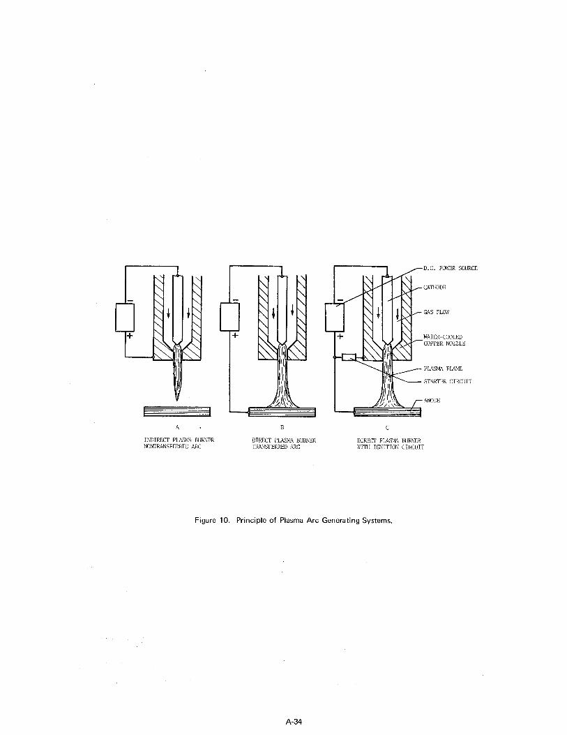
A. B
INDIRECT PLASMA BURNER DIRECT PLASMA BURNER NONTP.ANSFERRED ARC TRANSFERRED ARC
1 -D.C. POWER SOURCE
CATHIDE
GAS FLOW
WATER-COOLED COPPER NOZZLE
ANODE
C
DIRECT PLASMA HLlFtNER WITH IGNITION CIRCUIT
Figure IO. Principle of Plasma Arc Generating Systems.
A-34
5. Summary and Outlook
In a final assessment of the various production and pilot melting and refining processes for the alloy groups listed in Table 1, the following brief considerations may serve as concluding remarks and as an outlook towards future developments. A summary of the principal metallurgical possibilities of the processes covered in this review (Table 3) is presented in Table 6.
The chromium steels are melted in electric arc furnaces, frequently degassed, and at the present a large proportion is still cast conventionally into medium size ingots. Static cast ingot material shows strong anisotropy, particularly in toughness properties, which is caused by poor microcleanliness and banded structures due to microsegregation and delta-ferrite present. Delta-ferrite is controllable within certain limits by tijht chemical composition control and proper ingot/hot top design. There is, however, a definite, strong trend away from static cast material to consumably remelted chromium steels which provide very significant improvements in microcleanliness, minimized macro and microsegregations, and greatly improved transverse properties. Vacuum arc melting has been mostly used so far, but electroflux remelting may be favored in the future because of advantages regarding nitrogen control, workability, and yield. Primary melting will shift more to duplexing operations for economic reasons and better process control.
The predominant primary melting processes for the austenitic Cr-Ni steels and iron base superalloys are the electric furnace - often in combination with auxiliary refining units (VR processes, AOD) - and increasingly the vacuum induction furnace, especially for more demanding requirements. A significant proportion of the Cr-Ni steels is generally static cast into medium and large ingots, but consumable remelting is in - dispensible for heavy forging and other applications where isotropic properties are of importance. The strong trend to duplex primary melting systems and consumable re- melting will continue. In this group, VAR and EFR fulfil complementary roles, where- by vacuum arc remelting has first choice for alloys that require very close composition control, contain reactive elements, and are used in critical, rotating engine parts. Most of the iron base superalloys are double vacuum melted (VIM+VAR)for best control of the alloy chemistry, harmful tramp elements, and beneficial trace additions because these alloys are sensitive to rather minor compositional variations. Electroflux re- melting is preferred for alloys without reactive elements but containing volatile al- loying elements, like the solution-strengthened alloys. Alloys of this group are prime candidates for new melting techniques, such as plasma arc melting which some day may take place of the electric arc furnace.
Cobalt-nickel-chromium steels are largely melted in electric arc furnaces and cobalt base alloys in open induction furnaces or by the VIM process. Static casting is widely employed hut consumable processes, primarily electroflux remelting, have recently been favored to reduce inclusion content, minimize segregation problems, and improve technological properties. This alloy group has been rather slow in adapting new melting methods, although the application of duplex refining concepts, VIM, and EFR (VAR) has made progress and will certainly become more important in the future.
The most important group of superalloys, the nickel-base alloys, utilizes by far the most advanced melting and refining systems, since it always has pioneered the industrial introduction of new primary and secondary melting processes. Open melting in electric arc and induction furnaces in combination with auxiliary refining by vacuum processes or AOD is acceptable only for materials with lower to medium high temperature properties. Alloys containing substantial amounts of reactive elements and requiring very tight tiomposition control are almost exclusively produced by vacuum induction melting. VIM is presently the only proven primary industrial melting process providing the exact metallurgical conditions necessary for the reliable and consistent production of the
A-35
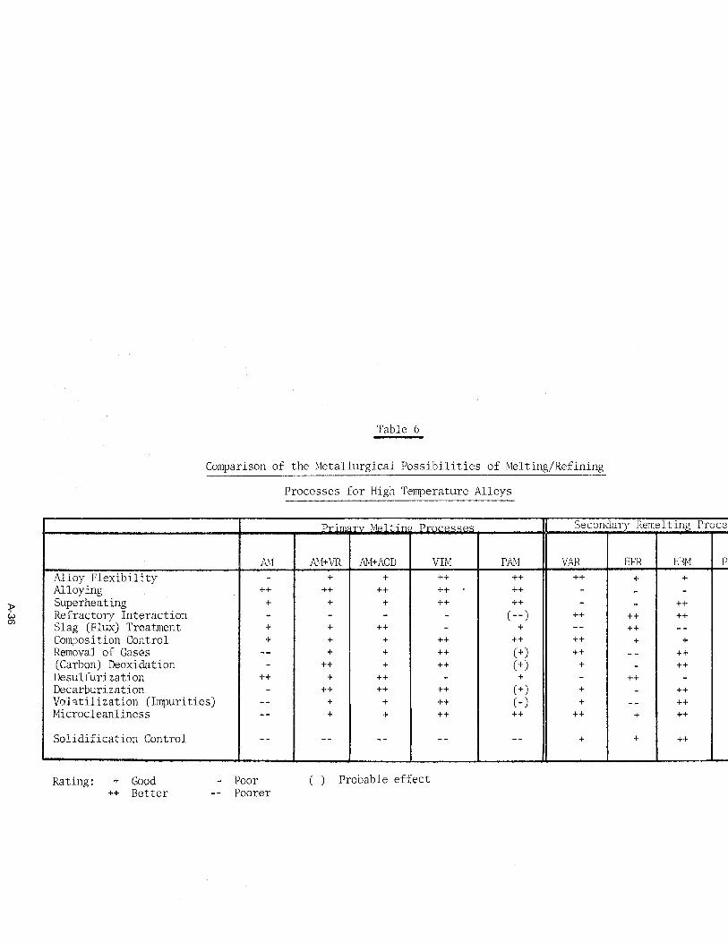
Table 6
Comparison of the Metallurgical Possibilities of Melting/Refining
Processes for High Temperature Alloys
I Drimca-mr Mnl+inn Dr~rnccnc II Secondary Remeltinrr Processes
Superheating Refractory Interaction Slag (Flux) Treatment Composition Control Removal of Gases (Carbon) Deoxidation Desulfurization Decarburization
Solidification Control
Rating : + Good - Poor ( ) Probable effect ++ Better -- Poorer
large variety of advanced superalloys. Vacuum arc remelting has been the dominant secondary melting process for most nickel-base superalloys and it will retain its importance for materials used in particularly demanding applications.
If open primary melting and casting must be used, then electroflux remelting is possibly advantageous over single VAR, providing equally good cleanliness but more favorable economics, although the actual remelting costs are about the same. It appears that double vacuum melting (VIM+VAR) and to some degree VIMtEFR will be the predominant production processes for superalloys throughout this decade. Electron beam remelting, which is in very limited production use today for superalloys and specialty steels, has a good growth potential and could become more important, if the present trend to much tighter impurity control should continue. Nonconsumable vacuum arc melting and plasma arc technology may well develop into acceptable industrial techniques for cer- tain specific a,pplicat;ions in the future. Plasma and inert electric arc melting processes will likely be in serious competition with the electric arc furnace and some auxiliary refining systems. Nithout any doubt, the increased competition be- tween the various processes will accelerate technological growth, further the better understanding of complex refining mechanisms, and provide more exact control of the solidification structures.
A-37
(1)
(2)
(3)
(4)
(5)
(6)
(7)
(8)
(9)
(10)
(11)
(12)
(13)
(14)
(15)
(16)
(17)
(18)
(19)
(20)
(21)
(22)
(23)
References
Clark, P. W., Martin, F. C., in "Steelmaking in the Basic Arc Furnace", I. S. I. Special Report No. 87 (1964), p.p. 60-77
Eliason, E. R., Kalling, U., J. Metals 20 (1968), 5, p.p. 56-61
Fitterer, G. R., Cassler, C. D., Vierbicky, V., J. Metals 20 (1968), 6, p.p. 74-78 Pargeter, J. K., Faurschou, D. K., J. Metals 21 (1969), 3, p.p.46-48
Choulet, R. J., Holmes, R. L. W., Chrzan, L. R., Proc. Elec. Fee. Conf., Vol. 23 (1965), p.p. 80-86
Spire, E., Strauss, T., Proc. Elec. Fee. Conf., Vol. 26 (1968), p.p. 104-108
Perrin, R., Starrat, F. W., J. Metals 9 (1957), p.p. 1517-1520
Anon., "33" The Magazine of Metals Producing, April 1965, p.p. 57-70, and I. S. I. Special Report No. 92 (1965), "VAcuum Degassing of Steel"
Nehrenberg, A. E., Clark, D. L., Schemel, J. M., J. Metals 17 (1965), 5, p.p. l-4
Finkl, C. W., Proc. Elec. Fee. Conf., Vol. 26 (1968), p.p. 109-111
Weiss, R. J., Schempp, E. G., Trans. Vacuum Met. Conf. 1969, p.p. 545-565
Bauer, H., Etterich, O., Fleischer, H. J., Otto, J., Stahl and Eisen 90 (1970), 14, p.p. 725-735
Tiberg, M., Kalling, U., Eliason, E. R., T,rans. Vacuum Met. Conf. 1967, p.p. 159- 168
ASEA Brochures 8544 Ea and 8556 Ea (1970). Ardito, V. P., Shaw, R. B., The AVR (Allegheny Vacuum Refining) Process, Presented at 80th AISI Meeting, New York, 1972
Sundberg, Y., Tiberg, H., "Clean Steel", Vol. 1 (Stockholm, 1971), p.p. 20-28
Saccomano, J. M., Choulet, R. J., Ellis, J. D., Proc. Elec. Fee. Conf., Vol. 26 (1968), p.p. 119-123
Irving, R. R., Iron Age, Nov. 11, 1971, p.p. 61-63
Darmara, F. N., J. Metals 19 (1967), 12, p.p. 42-48
Kinsman, G. T. M., Hazeldan, G. S. F., Davies, M. U., J. I. S. I. 207 (1969) p.p. 1463-1478
Aufderhaar, W. B., Metal Progress 93 (1968), 6, p. 135
Schlatter, R., Simkovich, A., Blast Fee. and Steel Plant Vol. 54 (1966), 11, p.p. 1029-1041
Schlatter, R., J. Metals 24 (1972), 5, p.p. 17-25
Hunt, C. d'A., Smith, H. R., Coad, R. C., Trans. Vacuum Met. Conf. 1969, p.p. 567-587 Schoberl, A., Holzgruber, W., Kahler, E., Archiv Eisenhuttenw; 39 (1968), p.p. 741- 745
A-38
(24)
(25)
(26)
(27)
(28)
(29)
(30)
(31)
(32)
(33)
(34)
(35)
(36)
(37)
(38)
(39)
(40)
(41)
(42)
(43)
(44)
(45)
(46)
Fischer, W. A., Etterich, O., Stahl u. Eisen 87 (1967), p.p. 28-34
Taylor, L. S., Briggs, R., Foundry Tr. J., July 27, 1967, p.p. 139-143
Magnolo, G., Can. Min. and Met. Bulletin, 1964, p.p. 57-62
Spiegelberg, K., Ebeling, F., Jakobs, W., Helmfried, J., Hoffmann, H., Neue Huette 12 (1967), 9, p.p. 542-550
Lowry, J. D., Schlienger, M. P., Proc. Third Int. Symp. on Electroslag and other Special Melting Techn. Part III, Pittsburgh, Pa, 1971, p.p. 83-99
Akers, R. R., Griffing, N., Buehl, R. C., Trans. Vacuum Met. Conf. 1969 p.p. 357-379
Vaia, A. R., Akers, R. R., Damon, S., Proc. Vat. Met. Conf. 1971 (AVS, New York), p.p. VM 13-18
Lempitsky, V. V., Okorokov, G, N., Bajarshinov, V. A., "Clean Steel", Vol. 2 (Stockholm, 1971), p.p. 29-44
Perry, T. E. et al., U.S. Patent No. 3, 387,967 (June 11, 1968)
Elliott, C. F., Evans, D. C., Kennedy, R. L., Manning, C. R., Metals Eng. Quart. 10 (1970), 2, p.p. 46-50
Cook, R. L., Reese, G. W., Gadsby, D. M., Third Int. Symp. on ESR and other Special Melting Techn. Part I, Mellon Inst., Pittsburgh (1971), p.p. 142-175
Barraclough, K. C., J. I. S. I. 20 (1969), p.p. 826-836
Schlatter, R., Trans. Vacuum Met. Conf. 1968, p.p. 333-354
Peter, W. Spitzer, H., Stahl u. Eisen 86 (1966), p.p. 1383-1393
Child, H. C., Oldfield, G. E., Iron and Steel Inst. Spec. Rept. NO. 77 (1963), p.p. 73-77
Diederichs, R., DEW Techn. Ber. 9 (1969), 2, p.p. 99-109
Preston, J., Trans. Vat. Met. Conf. 1967, p.p. 569-588
Copley, S. M., Giamei, A. F., Johnson, S. M., Hornbecker, M. F., Met. Trans. 1 (1970), p.p. 2193-2204
Smith, H. R., "Introduction to Electron Beam Technology", R. Bakich (Ed.), Wiley, New York, 1962, p.p. 168-183
Gruber, H., Dietrich, W., Erben, E., Heimerl, J.) Stephan, H., Trans. Vat. Met. Conf. 1962, p.p. 68-94
v.Ardenne, M., Schiller, S., Jaeger, G., Lenk, P., Schoenberg, H., Stein, P., Schmidt, K., Barsikow, G., Freiberger Forschungsh., B 122 (1966), P.P. 57-66
Hentrich, R., VI Int. Congr. on Electra-Heat, Brighton, 1968, Paper N. 136
Morton, A.G.S., Trans. Vat. Met. Conf. 1967, p.p. 759-770
A-39
(47) Paton, B. E. Lakomsky, VI., "Clean Steel". Vol. 2 (Stockholm, 1971), p.p. 77-92
(48) Rykalin, N. N., Pridandsev, 14. V., Stal in English, 1967, No. 9, p.p. 752-754
A-40


![Destilação - Aula 1_a [Modo de Compatibilidade]](https://img.pdfslide.net/doc/110x75/5571fd7f4979599169993b75/destilacao-aula-1a-modo-de-compatibilidade.jpg)