Embed Size (px)
Citation preview

Supercapacitor Energy Storage for
MRI SystemsDr Mihailo Ristic
Imperial College LondonMechanical Engineering Department
London, United Kingdom
Outline:• Motivation: MRI power supply requirements• MRI principles, main system components• Imaging sequences and duty cycles• Reference MRI system analysis• Experimental and simulation studies• Novel MRI for magic angle imaging
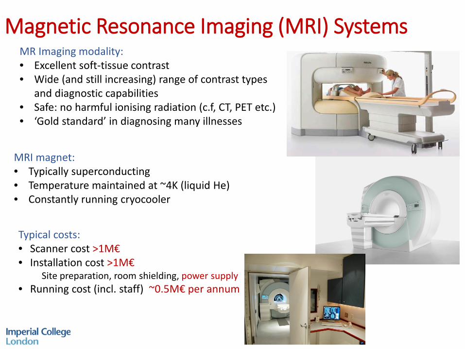
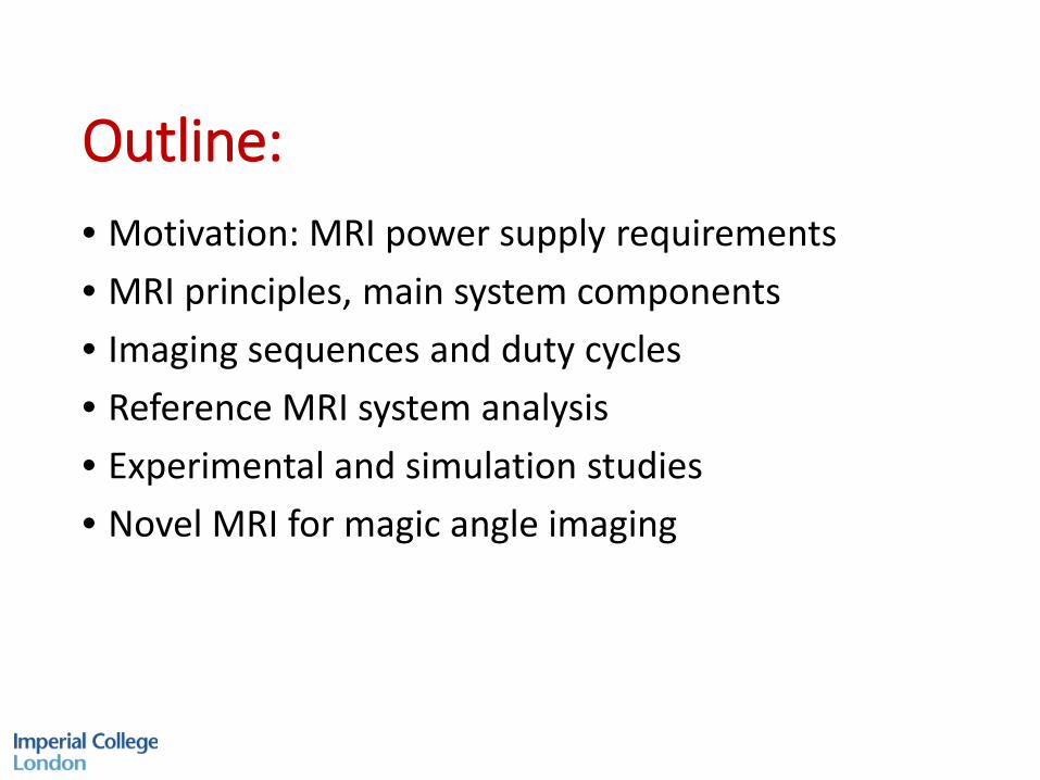
Magnetic Resonance Imaging (MRI) Systems
Typical costs:• Scanner cost >1M€• Installation cost >1M€
Site preparation, room shielding, power supply• Running cost (incl. staff) ~0.5M€ per annum
MR Imaging modality:• Excellent soft-tissue contrast• Wide (and still increasing) range of contrast types
and diagnostic capabilities• Safe: no harmful ionising radiation (c.f, CT, PET etc.)• ‘Gold standard’ in diagnosing many illnesses
MRI magnet:• Typically superconducting• Temperature maintained at ~4K (liquid He)• Constantly running cryocooler
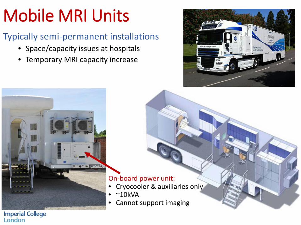
Mobile MRI UnitsTypically semi-permanent installations
• Space/capacity issues at hospitals• Temporary MRI capacity increase
On-board power unit:• Cryocooler & auxiliaries only• ~10kVA• Cannot support imaging
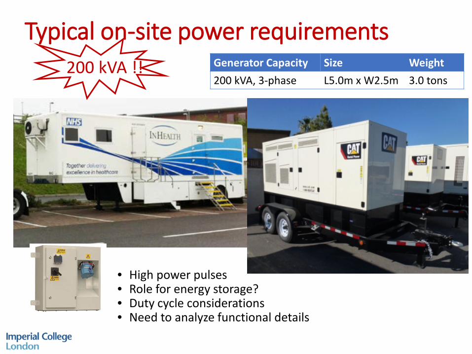
Typical on-site power requirementsGenerator Capacity Size Weight 200 kVA, 3-phase L5.0m x W2.5m 3.0 tons
200 kVA !!
• High power pulses• Role for energy storage?• Duty cycle considerations• Need to analyze functional details
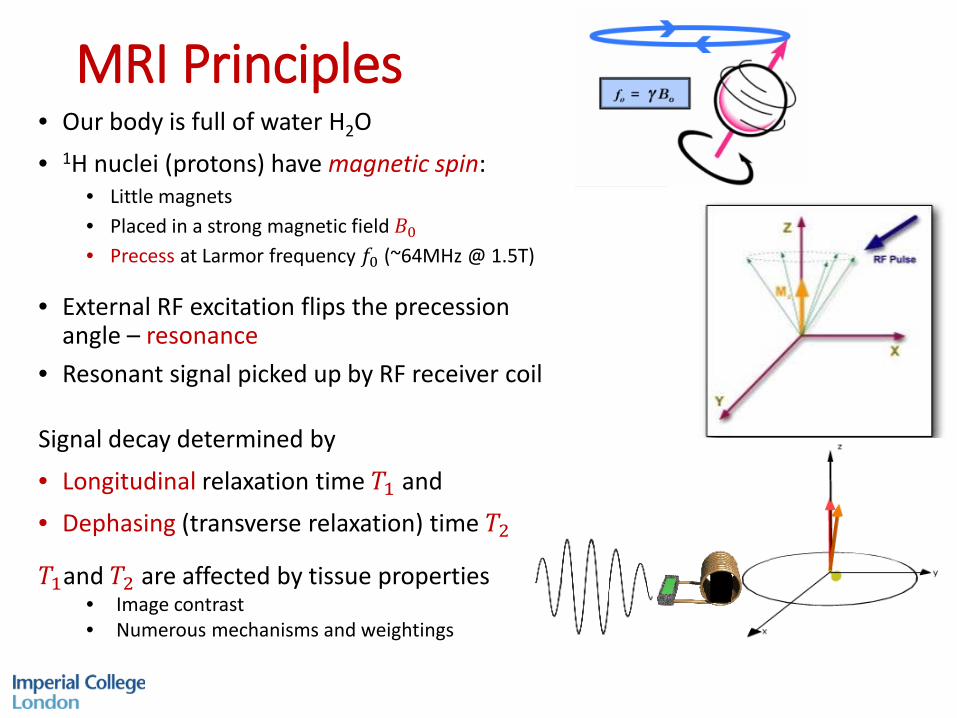
MRI Principles• Our body is full of water H2O• 1H nuclei (protons) have magnetic spin:
• Little magnets • Placed in a strong magnetic field 𝐵𝐵0• Precess at Larmor frequency 𝑓𝑓0 (~64MHz @ 1.5T)
• External RF excitation flips the precession angle – resonance
Signal decay determined by
• Longitudinal relaxation time 𝑇𝑇1 and • Dephasing (transverse relaxation) time 𝑇𝑇2
• Resonant signal picked up by RF receiver coil
𝑇𝑇1and 𝑇𝑇2 are affected by tissue properties• Image contrast• Numerous mechanisms and weightings
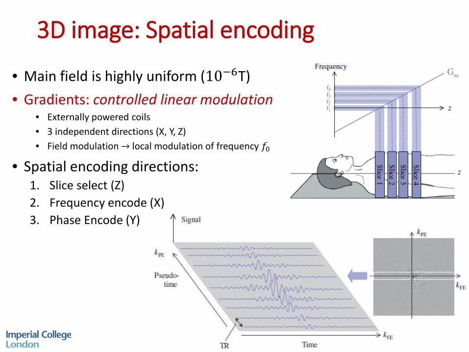
3D image: Spatial encoding
• Main field is highly uniform (10−6T)• Gradients: controlled linear modulation
• Externally powered coils• 3 independent directions (X, Y, Z)• Field modulation → local modulation of frequency 𝑓𝑓0
• Spatial encoding directions:1. Slice select (Z)2. Frequency encode (X)3. Phase Encode (Y)
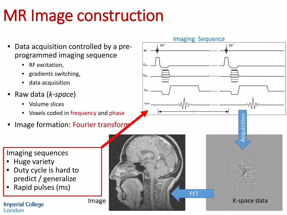
MR Image construction
• Data acquisition controlled by a pre-programmed imaging sequence
• RF excitation, • gradients switching, • data acquisition
• Raw data (k-space)• Volume slices• Voxels coded in frequency and phase
• Image formation: Fourier transform
RF
GSS
GPE
GFE
Signal
90° 90°
TR
Imaging Sequence
K-space dataImageFFT
Acqu
isitio
n
Imaging sequences• Huge variety• Duty cycle is hard to
predict / generalize• Rapid pulses (ms)
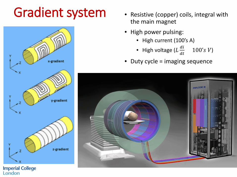
Gradient system • Resistive (copper) coils, integral with the main magnet
• High power pulsing:• High current (100’s A)
• High voltage (𝐿𝐿 𝑑𝑑𝑑𝑑𝑑𝑑𝑑𝑑
= 100’𝑠𝑠 𝑉𝑉)
• Duty cycle = imaging sequence
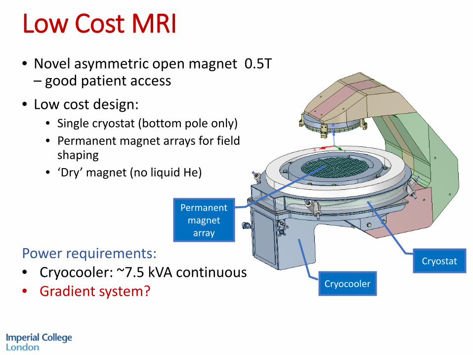
Low Cost MRI• Novel asymmetric open magnet 0.5T
– good patient access• Low cost design:
• Single cryostat (bottom pole only)• Permanent magnet arrays for field
shaping• ‘Dry’ magnet (no liquid He)
Cryostat
Cryocooler
Permanent magnet
array
Power requirements:• Cryocooler: ~7.5 kVA continuous• Gradient system?
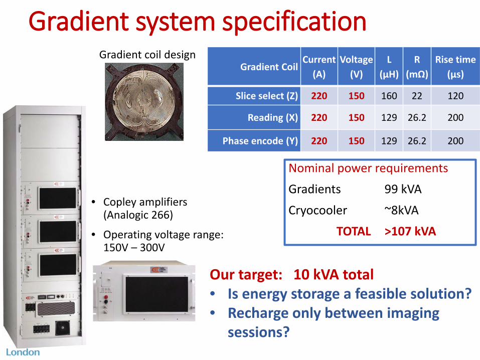
Gradient system specification
• Copley amplifiers (Analogic 266)
• Operating voltage range: 150V – 300V
Gradient CoilCurrent
(A)Voltage
(V)L
(μH)R
(mΩ)Rise time
(μs)
Slice select (Z) 220 150 160 22 120
Reading (X) 220 150 129 26.2 200
Phase encode (Y) 220 150 129 26.2 200
Gradient coil design
Nominal power requirementsGradients 99 kVA
Cryocooler ~8kVATOTAL >107 kVA
Our target: 10 kVA total• Is energy storage a feasible solution?• Recharge only between imaging
sessions?
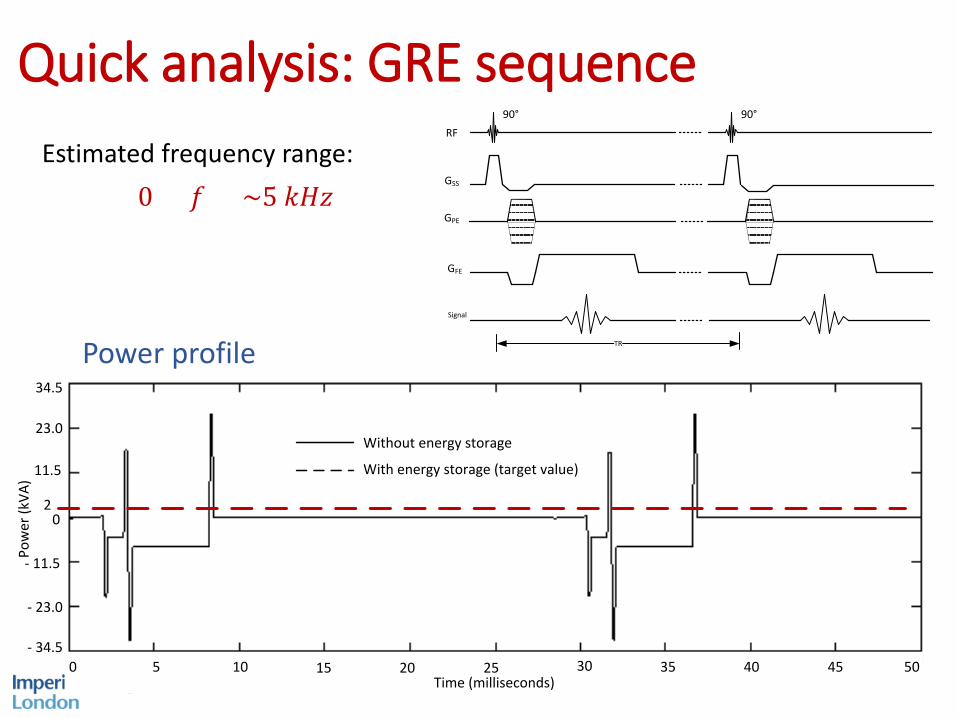
Quick analysis: GRE sequence
Power profile
RF
GSS
GPE
GFE
Signal
90° 90°
TR
Pow
er (k
VA)
34.5
23.0
- 23.0
- 34.5
11.5
- 11.5
0
Time (milliseconds) 0 5 10 15 20 25 30 35 40 45 50
2
Without energy storage
With energy storage (target value)
Estimated frequency range:0 < 𝑓𝑓 < ~5 𝑘𝑘𝑘𝑘𝑘𝑘
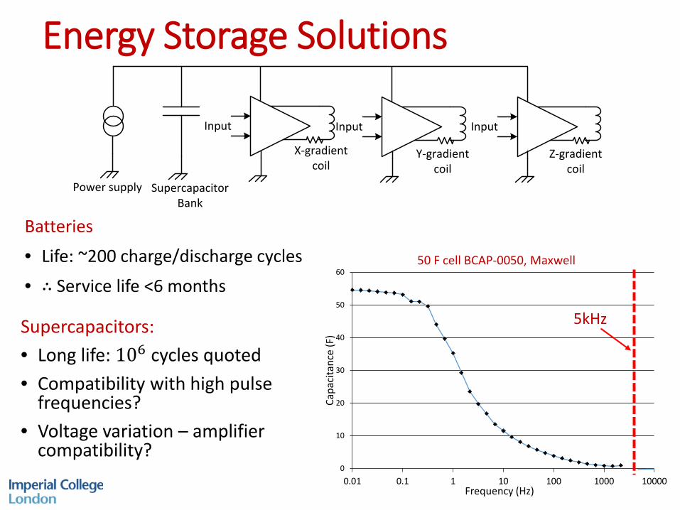
Energy Storage Solutions
Batteries• Life: ~200 charge/discharge cycles
• ∴ Service life <6 months
Input
X-gradient coil
Y-gradient coil
Z-gradient coil
SupercapacitorBank
Power supply
Input Input
0
10
20
30
40
50
60
0.01 0.1 1 10 100 1000 10000
Capa
cita
nce
(F)
Frequency (Hz)
50 F cell BCAP-0050, Maxwell
5kHzSupercapacitors:• Long life: 106 cycles quoted• Compatibility with high pulse
frequencies?• Voltage variation – amplifier
compatibility?
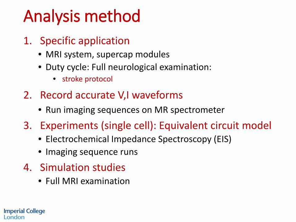
Analysis method1. Specific application
• MRI system, supercap modules• Duty cycle: Full neurological examination:
• stroke protocol
2. Record accurate V,I waveforms• Run imaging sequences on MR spectrometer
3. Experiments (single cell): Equivalent circuit model • Electrochemical Impedance Spectroscopy (EIS)• Imaging sequence runs
4. Simulation studies• Full MRI examination
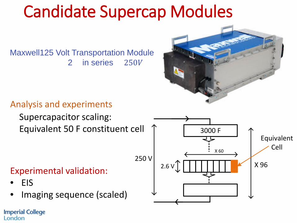
Candidate Supercap Modules
Analysis and experimentsSupercapacitor scaling:Equivalent 50 F constituent cell
Maxwell125 Volt Transportation Module 2 × in series = 250𝑉𝑉
3000 F
X 96
Equivalent Cell
250 V2.6 V
X 60
Experimental validation:• EIS• Imaging sequence (scaled)
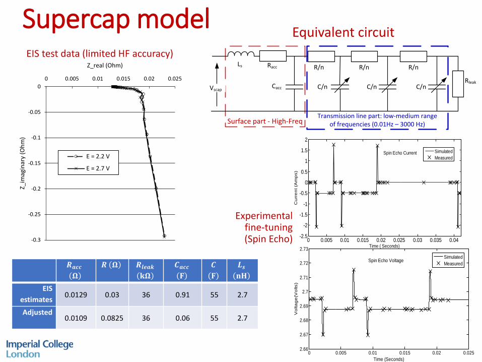
Supercap model Equivalent circuit
Surface part - High-Freq
RaccLs R/n R/n
RleakC/n C/nCacc
R/n
C/n
Transmission line part: low-medium rangeof frequencies (0.01Hz – 3000 Hz)
Vscap
-0.3
-0.25
-0.2
-0.15
-0.1
-0.05
00 0.005 0.01 0.015 0.02 0.025
Z_im
agin
ary
(Ohm
)
Z_real (Ohm)
E = 2.2 V
E = 2.7 V
𝑹𝑹𝒂𝒂𝒂𝒂𝒂𝒂𝛀𝛀
𝑹𝑹 𝛀𝛀 𝑹𝑹𝒍𝒍𝒍𝒍𝒂𝒂𝒍𝒍𝐤𝐤𝛀𝛀
𝑪𝑪𝒂𝒂𝒂𝒂𝒂𝒂𝐅𝐅
𝑪𝑪𝐅𝐅
𝑳𝑳𝒔𝒔𝐧𝐧𝐧𝐧
EIS estimates 0.0129 0.03 36 0.91 55 2.7
Adjusted0.0109 0.0825 36 0.06 55 2.7
EIS test data (limited HF accuracy)
0 0.005 0.01 0.015 0.02 0.025 0.03 0.035 0.04-2.5
-2
-1.5
-1
-0.5
0
0.5
1
1.5
2
Time ( Seconds)
Cu
rre
nt (
Am
ps)
Spin Echo Current
SimulatedMeasured
0 0.005 0.01 0.015 0.02 0.0252.66
2.67
2.68
2.69
2.7
2.71
2.72
2.73
Spin Echo Voltage
Time (Seconds)
Vo
ltag
e(V
olts
)
SimulatedMeasured
Experimental fine-tuning(Spin Echo)
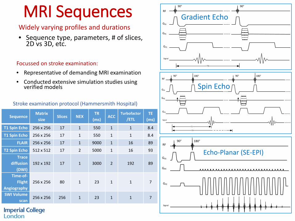
MRI SequencesWidely varying profiles and durations• Sequence type, parameters, # of slices,
2D vs 3D, etc.
RF
GSS
GPE
GFE
Signal
90° 90°
TR
Spin Echo90° 180°
RF
GSS
GPE
GFE
Signal
TE
TR
90° 180°
Gradient Echo
90° 180° RF
GSS
GPE
GFE
Signal
Echo-Planar (SE-EPI)
SequenceMatrix
sizeSlices NEX
TR (ms)
ACCTurbofactor
/ETLTE
(ms)
T1 Spin Echo 256 x 256 17 1 550 1 1 8.4
T1 Spin Echo 256 x 256 17 1 550 1 1 8.4
FLAIR 256 x 256 17 1 9000 1 16 89
T2 Spin Echo 512 x 512 17 2 5000 1 16 93Trace
diffusion (DWI)
192 x 192 17 1 3000 2 192 89
Time-of-Flight
Angiography256 x 256 80 1 23 1 1 7
SWI Volume scan
256 x 256 256 1 23 1 1 7
Stroke examination protocol (Hammersmith Hospital)
Focussed on stroke examination:• Representative of demanding MRI examination• Conducted extensive simulation studies using
verified models
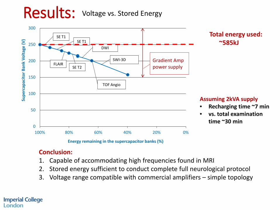
Results:
0
50
100
150
200
250
300
0%20%40%60%80%100%
Supe
rcap
acito
r Ban
k Vo
ltage
(V)
Energy remaining in the supercapacitor banks (%)
SWI-3D
TOF Angio
DWI
SE T1SE T1
FLAIRSE T2
Gradient Amp power supply
Voltage vs. Stored Energy
Conclusion:1. Capable of accommodating high frequencies found in MRI2. Stored energy sufficient to conduct complete full neurological protocol3. Voltage range compatible with commercial amplifiers – simple topology
Total energy used:~585kJ
Assuming 2kVA supply• Recharging time ~7 min• vs. total examination
time ~30 min
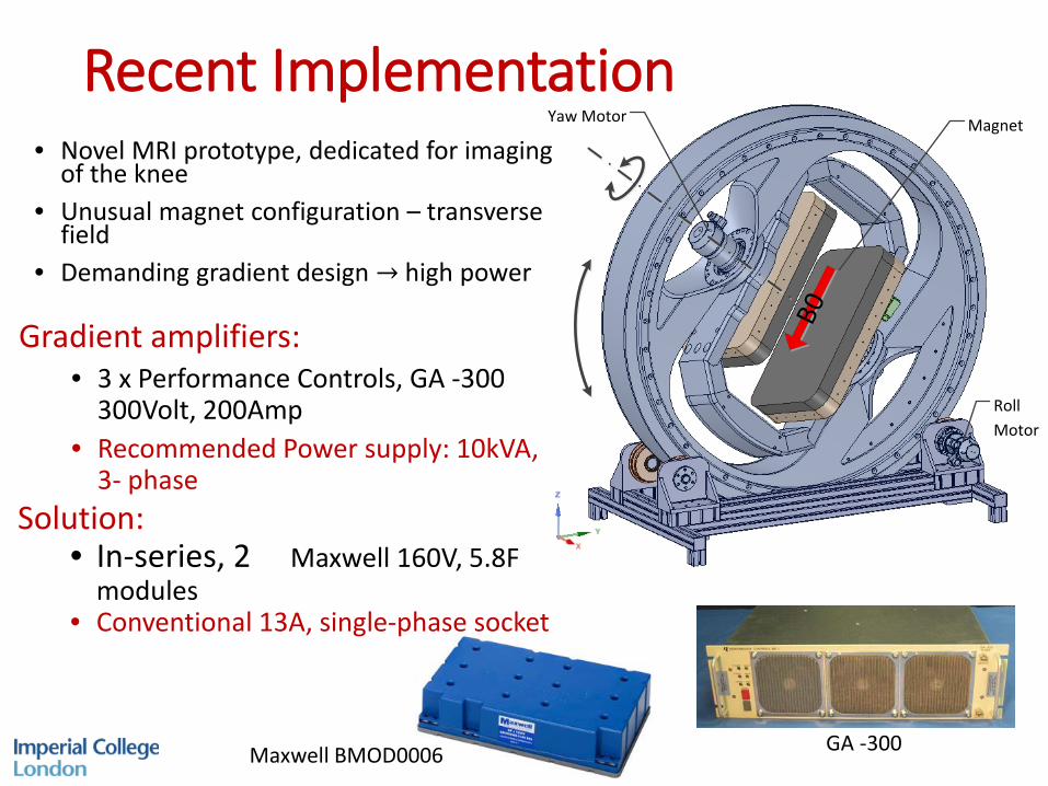
Recent ImplementationYaw Motor
Roll Motor
Magnet
B0
• Novel MRI prototype, dedicated for imaging of the knee
• Unusual magnet configuration – transverse field
• Demanding gradient design → high power
GA -300 Maxwell BMOD0006
Gradient amplifiers:• 3 x Performance Controls, GA -300
300Volt, 200Amp• Recommended Power supply: 10kVA,
3- phaseSolution:
• In-series, 2 × Maxwell 160V, 5.8F modules
• Conventional 13A, single-phase socket
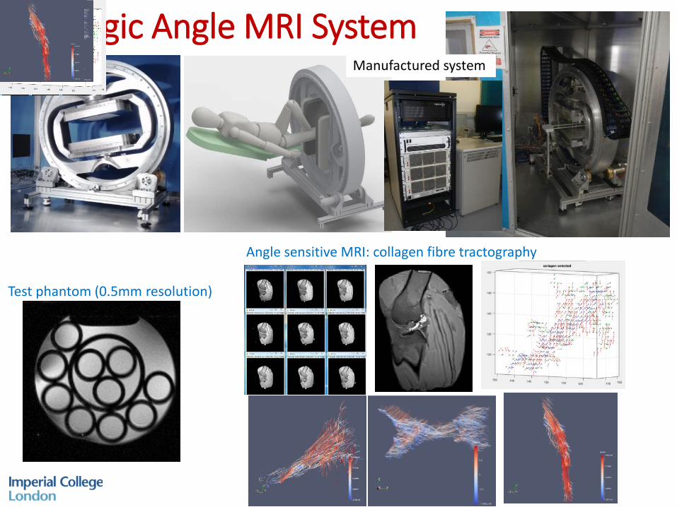
Magic Angle MRI System
Test phantom (0.5mm resolution)
Angle sensitive MRI: collagen fibre tractography
Manufactured system
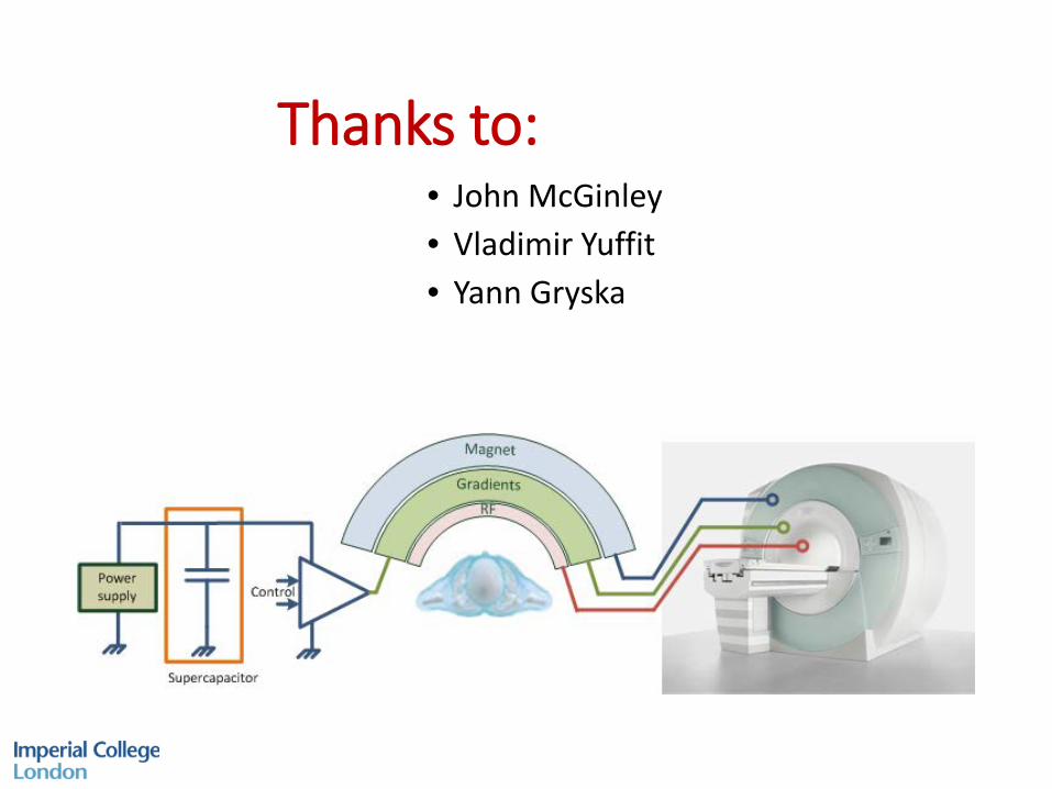
Thanks to:• John McGinley• Vladimir Yuffit• Yann Gryska