Embed Size (px)
Citation preview


• Superconducting MAGnetically LEVitated vehicle
• Utilises magnets and linear electric motor technology
• Reach speeds of up to 552kmh.

• Magnetic field applied to a superconductor sets up electrical currents; they conspire to cancel the magnetic field.
•Result – if a small magnet is placed over a superconducting dish it will float.
• “Superconducting levitation” – a method for providing very smooth transport for high speed trains.

• Magnetised coil running along track (guideway) repels large magnets on train’s undercarriage. Train levitates.
• Power supplied to coils – unique system magnetic fields push train along
• Changes in polarity – thrust.

• very high speed
•Reliability
•Safety
•Minimum maintenance
•Low environmental impact
Germany – Levitation results from attraction. Japan – Levitation achieved by repulsion.
-Research began 1970
-1990 – Yamanachi Maglev test line – opened 1997
-April 1999 – 552 kmh.

• Superconducting Quantum Interference Device (SQUID)
•Josephson effect - switches
•With superconductivity application computers can run up to ten times faster.

• Resistance in wires eliminated.
• Reduced environmental problems – enormous amounts of energy saved.
• More energy efficient

Sensitivity of a telescope is a measure of its light gathering power.
Resolution is the ability of a telescope to clearly distinguish between 2 very close objects
• The larger the apeture, the more sensitive the telescope – the more light can be detected.
• The bigger the lens the better the resolution – less chance of diffraction fringes joining for 2 objects.

1. ADAPTIVE OPTICS
2. INTERFEROMETRY
3. ACTIVE OPTICS
• These 3 techniques are used to improve upon the resolution and sensitivity of ground – based systems. When looking into space, scientists apply these in new generation optical telescopes.

Adaptive optics systems consist of 3 major parts:
1. wavefront sensor
2. Wavefront correction device ( tilt tip mirror + flexible mirror
3. Computer (analyses and controls)
• Part of incident light is sampled.
• Atmospheric distortion measured by wavefront sensor.
• Information is fed back to the wavefront correction device.
• Light that has been bent by atmosphere can be effectively ‘straightened out’.
This technique involves measuring and compensating for the atmospheric effects.
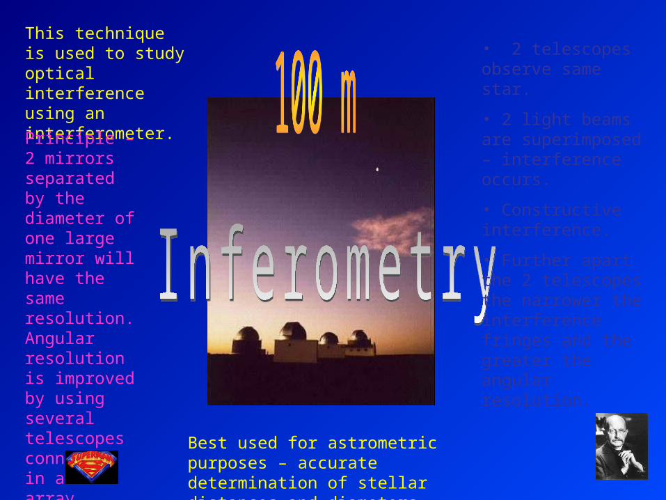
This technique is used to study optical interference using an interferometer.
Principle – 2 mirrors separated by the diameter of one large mirror will have the same resolution. Angular resolution is improved by using several telescopes connected in an array.
• 2 telescopes observe same star.
• 2 light beams are superimposed – interference occurs.
• Constructive interference.
• Further apart the 2 telescopes the narrower the interference fringes and the greater the angular resolution.
Best used for astrometric purposes – accurate determination of stellar distances and diameters.

This is a technique that involves measuring and compensating for imperfections in the telescope mirror.
• Actuators push and pull on back surface of mirror – ‘actively controlling’.
• Similar to adaptive optics….much slower.
• Control ensures that even if the mirror’s shape is not perfect, large scale errors can be controllled.