Embed Size (px)
Citation preview

INEEL/EXT-03-01210
Supercritical Water Reactor (SCWR)
Progress Report for the FY-03 Generation-IV R&D Activities for the Development of the
SCWR in the U.S.
Jacopo Buongiorno, U.S. SCWR Product Manager, INEEL
Philip E. MacDonald, INEEL
September 30, 2003

Executive Summary Supercritical water cooled reactors (SCWRs) are essentially light water reactors (LWRs)
operating at higher pressure and temperature. SCWRs achieve high thermal efficiency (i.e., about 45% vs. about 35% efficiency for advanced LWRs) and are simpler plants as the need for many of the traditional LWR components such as the coolant recirculation pumps, pressurizer, steam generators, and steam separators and dryers is eliminated. SCWRs build upon two proven technologies, the LWR and the supercritical coal-fired boiler. The main mission of the SCWR is production of low-cost electricity. Thus the SCWR is also suited for hydrogen generation with electrolysis, and can support the development of the hydrogen economy in the near term. SCWRs are one of only six reactor technologies currently being studied under the Generation-IV international program.
In FY-03 the Generation-IV SCWR program in the U.S. comprised six tasks involving six organizations, i.e., Idaho National Engineering and Environmental Laboratory (INEEL), Argonne National Laboratory (ANL), Oak Ridge National Laboratory (ORNL), the Westinghouse Electric Company (including the BWR Engineering group in Sweden), Burns & Roe Enterprises Inc. (BREI) and the Massachusetts Institute of Technology (MIT). The total budget for FY-03 was $438k with the cost breakdown reported in Table E.I. The objective of the multi-year SCWR program is to assess the technical viability of the SCWR concept. Thus, as per the guidelines in the Generation-IV Roadmap Report, the focus is on establishing a conceptual design, assessing its safety and stability characteristics, and identifying and testing candidate materials for all reactor components.
The team has selected a reference design for the SCWR system that focuses on a large-size, dmoderated, low-enriched uranium fuelled, base-locapital and operating costs. The operating pressur280/500°C, respectively. The coolant density decre90 kg/m3 at the core outlet. Thus, large square watmoderation in the core. The fuel pin design is simiwith higher fill pressure and longer fission gas plevessel internal components have been identified by Oswelling austenitic steels for the components exposesteels and nickel-based alloys for low-dose componpotentially aggressive SCWR environment, and thedevelopment program has been prepared for this pur
Two traditional austenitic steels (304L anMichigan for corrosion and stress-corrosion crackinfound that both alloys are susceptible to SCC (31deaerated high-temperature (>400°C) supercritical temperature components in the SCWR. However,
Table E.I. Task and cost breakdown for the U.S. Generation-IV SCWR program in FY-03.
Task Organization Budget ($k)
Program Management INEEL 75 Balance of plant design, control and start-up
BREI 50
Stability analysis ANL 53 Containment and safety systems design
Westinghouse 160
Materials survey ORNL 50 Corrosion testing of candidate materials
MIT 50
Total 438
2
irect-cycle, thermal-spectrum, light-water cooled and ad operation plant for electricity generation at low e and core inlet/outlet temperatures are 25 MPa and ases from about 760 kg/m3 at the core inlet to about er rods with down flow are used to provide adequate lar to that of a pressurized water reactor (PWR), but num. Candidate materials for all fuel assembly and
RNL and include ferritic-martensitic steels and low-d to high neutron doses, and high-strength austenitic ents. However, these materials are un-proven in the ir performance will have to be tested. A materials
pose.
d 316L) were tested at MIT and the University of g (SCC) susceptibility in supercritical water. It was 6L less so than 304L) in both deaerated and non-water. Thus, these alloys cannot be used for high-they could be used for components operating in the

3
280-350°C range (e.g., the lower core plate, the control rod guide tubes), given their satisfactory behavior in deaerated water at these temperatures.
The SCWR core average power density is about 70 kW/L, i.e., between the power density of boiling water reactors (BWRs) and PWRs. The core rated thermal power is 3,575 MW resulting in a pressure vessel of 5.3-m inner diameter and 46-cm thickness in the beltline region. The vessel operates at 280°C and traditional LWR low-alloy steels such as SA-508 can be used. Because of its large size the vessel cannot be manufactured in the U.S., but appears to be within existing manufacturing capabilities in Japan. The vessel was sized by Westinghouse per the ASME Code regulations, and its structural performance was verified with detailed 3D finite-element analyses.
The reactor coolant system of the SCWR comprises the feedwater lines and main steam lines up to the outermost set of containment isolation valves. Similar to a BWR, the SCWR uses two feedwater lines made of carbon steel. However, BREI has determined that because of its high-density steam, the SCWR needs only two steam lines as opposed to four in a BWR of similar thermal power. This further adds to the economic strength of the SCWR concept. The steam lines can be constructed out of ferritic steels such as P91 and P92, which are currently used in supercritical fossil plant steam lines, although the latter would have to be included in Section III (nuclear components) of the ASME Code.
A pressure-suppression type containment with a condensation pool, essentially the same design as modern BWRs, was selected by Westinghouse. The dry and wet well volumes were calculated to limit the pressure build-up to typical BWR levels following a LOCA or a severe accident with core melting. The condensation pool water inventory was designed to provide ample margin for residual heat removal and meet the requirement that active safety systems are not needed during the first 24 hours following an initiating event resulting in a severe accident. The very conservative European Utility Requirements for mitigation of severe accidents were adopted in sizing the containment and a core catcher was added to the design. Despite this conservative approach the SCWR containment is somewhat smaller than that of an advanced BWR of similar thermal power, and thus significantly smaller on a per unit electric power basis. Following a critical review of the severe accident mitigation strategy, further reduction of the containment volumes will be explored in FY-04.
Thermal-hydraulic and thermal-nuclear coupled instabilities were investigated at ANL with a
frequency-domain linear stability analysis code based on single-channel thermal hydraulics, one-dimensional fuel heat conduction, and point-kinetics models. The BWR stability criteria were adopted and it was found that the SCWR is stable against core-wide in-phase oscillations at normal operating power and flow conditions.
A critical review of the LWR abnormal events and their NRC classification has been performed by Westinghouse and INEEL with the SCWR application in mind. Four events were singled out that could be potentially troublesome: (i) loss of feedwater flow, which in the once-through direct-cycle SCWR coincides with the loss of core flow, (ii) turbine trip without steam bypass, which pressurizes the system and could result in significant positive reactivity insertion because of the low density of the SCWR coolant, (iii) loss of feedwater heating, which also results in the insertion of positive reactivity because of the lack of feedwater mixing with hotter coolant in the vessel, and (iv) large break in the feedwater lines, which, if unmitigated, results in coolant stagnation in the core and rapid overheating of the fuel. A preliminary analysis of these four key events was performed at INEEL with a modified version of the RELAP5 code. It was found that the SCWR behavior is relatively benign during the turbine trip without steam bypass, the loss of feedwater heating, and the large break in the feedwater lines. On the other hand, survival of the total loss of feedwater will likely require the use of a high-capacity high-pressure fast-acting auxiliary feedwater system. Design of such system will be a major challenge.

4
The reference SCWR system has a power conversion cycle that is very similar to a supercritical coal-fired plant, with the boiler replaced by the nuclear reactor. A conceptual study was performed by BREI to identify an optimal configuration for the goals of thermal efficiency maximization and capital cost minimization. The SCWR power conversion cycle uses a single-shaft turbine-generator, operating at reduced speed (1,800 rpm), with one high-pressure/intermediate-pressure (HPT/IPT) turbine unit and three low-pressure turbine (LPT) units with six flow paths, with a moisture separator reheater between the HPT/IPT and the LPTs, eight feedwater heaters, steam-turbine-driven feedwater pumps and natural draft cooling towers. The reference design generates 1,600 MWe with a thermal efficiency (net electric power to the grid / fission power) of 44.8% versus about 35% for LWRs under equivalent assumptions.
The feasibility of the 1,600-MWe turbine-generator was verified by BREI with various turbine
vendors. A stage-by-stage model of the HPT/IPT and LPT was generated and demonstrated that the steam parameters at the turbine inlet, the steam speeds in the LPT exhaust annulus, the LPT blade lengths and moisture content are all within current standard ranges for steam turbines. Note that the overall physical size of the SCWR turbine generator is similar to a 1,300-1,500 MWe LWR turbine generator because the volumetric steam flow processed in the LPT is similar for both plants. All other major components including the feedwater heaters, pumps, cooling tower, steam lines, condenser, etc. have been sized and are either commercially available or within current design capabilities. Candidate materials for all components of the power conversion cycle have been identified by ORNL based on the fossil-plant experience.
A pre-conceptual design of the SCWR control system was also performed by BREI. The main characteristics affecting the design of the SCWR control system are the relatively low vessel water inventory, the nuclear/thermal-hydraulic coupling, the lack of level indication under supercritical conditions and the absence of recirculation flow. The main variables to be controlled include the reactor power, the core outlet temperature during supercritical pressure operation (e.g., full power operation), the reactor pressure, the reactor level during subcritical pressure operation (e.g., during start-up) and the feedwater flow. Then, assuming base-load operation, the recommended approach for the SCWR is one in which the control rods accomplish the primary control of the thermal power, the turbine control valve provides the control of the pressure, the feedwater flow (i.e., the feedwater pumps) provides the primary control of the outlet temperature, and the control of the coolant inventory in the vessel is accomplished by assuring that steam and feed flow are balanced while maintaining the correct core outlet temperature. Also, rather than an approach in which higher functions such as power or turbine valve control are in manual with lower level control loops in automatic, the use of an integrated control approach, one in which all functions are in automatic, is deemed preferable due to the SCWR’s expected fast response to perturbations.
Start-up and shutdown procedures and related equipment for supercritical fossil plants were
reviewed and their applicability to the SCWR plant was assessed. BREI determined that the use of a hybrid variable pressure start-up approach is preferable. This approach requires a start-up turbine bypass, a steam-water separator, drain valves, and recirculation pumps. The integrated control system will vary the pressure during start-up, but will do so in discrete steps with about three pressure set-points that will be established by the operator until supercritical operation is reached. The needed sequence and procedures for both start-up and shutdown of the SCWR plant were developed. The start-up procedures are similar to a LWR except for the transition to and from supercritical-pressure operation.
The issue of transport of coolant activation products to the balance of plant was also evaluated at
INEEL. It was found that the 16N activity in the SCWR steam is about twice that in the steam of a BWR with hydrogen water chemistry. However, a simple gamma attenuation model showed that this results in shielding requirements for the SCWR only up to 12% higher than for the BWR. Moreover, because of

5
the higher SCWR electric power, the specific shielding costs ($/kWe) associated with 16N are expected to be similar to or better than the BWR’s.
In summary, the research work during the first year of the Generation-IV SCWR program has confirmed the basic assumptions contained in the Generation-IV Roadmap Report regarding the SCWR, and no new potential showstoppers have been found. The key feasibility issues for the SCWR remain the development of in-core materials and the demonstration of adequate safety. Dynamic instabilities appear to be less of a concern.
Detailed technical information on the experiments and analyses briefly discussed in this report
can be found in the annual progress reports produced by the performing organizations, which are available from the SCWR Product Manager upon request.

6
Table of Contents EXECUTIVE SUMMARY......................................................................................................................................... 2
TABLE OF CONTENTS............................................................................................................................................ 6
1. INTRODUCTION AND COSTS .......................................................................................................................... 7
2. TECHNICAL PROGRESS IN FY-03 .................................................................................................................. 8 2.1 GENERAL PLANT CHARACTERISTICS .................................................................................................................. 8 2.2 REACTOR PRESSURE VESSEL (RPV) ................................................................................................................... 9 2.3 CORE AND FUEL ASSEMBLY DESIGN AND MATERIALS SELECTION .................................................................. 11 2.4 VESSEL INTERNALS DESIGN AND MATERIALS SELECTION................................................................................ 15 2.5 REACTOR COOLANT SYSTEM............................................................................................................................ 17 2.6 CONTAINMENT.................................................................................................................................................. 18 2.7 DYNAMIC ANALYSIS OF THE SCWR REFERENCE PLANT.................................................................................. 20
2.7.1 Stability Analysis ................................................................................................................................... 20 2.7.2 Preliminary Analysis of Key Transients and Accidents................................................................... 20
2.8 BALANCE OF PLANT (BOP) ............................................................................................................................... 23 2.9 CONTROL STRATEGY ........................................................................................................................................ 27 2.10 START-UP PROCEDURES AND RELATED EQUIPMENT....................................................................................... 28 2.11 COOLANT ACTIVATION (N-16) ....................................................................................................................... 31
3. PROGRAM MANAGEMENT ........................................................................................................................... 32
4. OTHER SCWR ACTIVITIES IN THE U.S. ..................................................................................................... 32
5. CONCLUSIONS .................................................................................................................................................. 37
6. REFERENCES..................................................................................................................................................... 38

1. Introduction and Costs The supercritical water-cooled reactor (SCWR) is one of the six reactor technologies selected for
research and development (R&D) under the Generation-IV program. SCWRs are promising advanced nuclear systems because of their high thermal efficiency (i.e., about 45% vs. about 33% efficiency for current Light Water Reactors, LWRs) and considerable plant simplification. SCWRs are basically LWRs operating at higher pressure and temperatures with a direct once-through cycle. Operation above the critical pressure eliminates coolant boiling, so the coolant remains single-phase throughout the system. Thus the need for recirculation and jet pumps, pressurizer, steam generators, steam separators and dryers is eliminated. The main mission of the SCWR is generation of low-cost electricity. It is built upon two proven technologies, LWRs, which are the most commonly deployed power generating reactors in the world, and supercritical fossil-fired boilers, a large number of which is also in use around the world. The SCWR concept is being investigated by 32 organizations in 13 countries. General information about the SCWR concept and its technical challenges is widely available in the literature [GIF 2002, Kataoka et al. 2002, Spinks et al. 2002, Squarer et al. 2002], and will not be repeated here.
In the U.S. the Generation-IV SCWR program is led by the INEEL and operates under the following general assumptions, which are consistent with the SCWR’s focus on electricity generation at low capital and operating costs:
♦= Direct cycle, ♦= Thermal spectrum, ♦= Light-water coolant and moderator, ♦= Low-enriched uranium oxide fuel, ♦= Base load operation1.
In FY-03 the Generation-IV SCWR program in the U.S. comprised six tasks involving six
organizations, i.e., INEEL, ANL, ORNL, the Westinghouse Electric Company (including the BWR Engineering group in Sweden), Burns & Roe Enterprises Inc. (BREI) and MIT. The total budget was $438,000 with the cost breakdown shown in Table I. Excellent technical progress has been made, and all the milestones indicated in the program plan were met on time. The key technical findings are explained in Section 2, program management activities are reported in Section 3, while other non-Generation-IV SCWR activities in the U.S. (including NERI and I-NERI projects) are briefly discussed in Section 4.
All the technical details of the
analyses and experiments mentioned in this report can be found in the following publications, which are available from the SCWR Product Manager upon request:
1 Similar assumptions are adopted in other countrielight-water-cooled, heavy-water-moderated SCWR
Table I. Task and cost breakdown for the U.S. Generation-IV SCWR program in FY-03.
Task Organization Budget ($k)
Actuals* ($k)
Program Management INEEL 75 75 Balance of plant design, control and start-up
BREI (INEEL subcontract)
50 50
Stability analysis ANL 53 53 Containment and safety systems design
Westinghouse 160 101
Materials survey ORNL 50 50 Corrosion testing of candidate materials
MIT (INEEL subcontract)
50 50
Total 438 379 * As of 9/29/03
7
s with the notable exception of Canada were the focus is on a concept.
8
1) Balance of plant, reactor control and start-up (BREI)
Burns & Roe Enterprises Inc., Supercritical Water Reactor (SCWR), Study of Power Conversion Cycle, Control Strategy and Start-up Procedures, September 2003.
2) Stability analysis (ANL)
W. S. Yang, N. Zavaljevski, Preliminary Investigation of Power-Flow Instabilities of Supercritical Water Reactor, Argonne National Laboratory, September 2003. W. S. Yang, N. Zavaljevski, “Preliminary Stability Analysis for Supercritical Water Reactor”, Paper 87886, Proceedings of Global 2003, New Orleans, November 16-20, 2003.
3) Containment and safety systems design (Westinghouse)
N. O. Jonsson, U. Bredolt, T. A. Dolck, A. Johanson, T. Ohlin, L. Oriani, L. Conway, SCWR - Design Review and Design of Safety Systems and Containment – Status, September 2003, SE-03-044 (Rev. 0), September 2003.
4) Materials survey (ORNL, INEEL)
J. Buongiorno, W. Corwin, P. E. MacDonald, L. Mansur, R. Nanstad, R. Swindeman, A. Rowcliffe, G. Was, D. Wilson, I. Wright, Supercritical Water Reactor (SCWR), Survey of Materials Experience and R&D Needs to Assess Viability, INEEL/EXT-03-00693 (Rev. 1), Idaho National Engineering and Environmental Laboratory, September 30, 2003.
5) Corrosion testing of candidate materials (MIT, University of Michigan)
J. McKinley, S. Teysseyre, G. S. Was, D. B. Mitton, H. Kim, J-K Kim, and R. M. Latanision, “Corrosion and Stress Corrosion Cracking of Austenitic Alloys in Supercritical Water”, Paper 1027, Proceedings of GENES4/ANP2003, Kyoto, JAPAN Paper 1027, Sep. 15-19, 2003.
2. Technical Progress in FY-03 2.1 General Plant Characteristics
The reference SCWR design for the U.S. program is a direct cycle system operating at 25.0 MPa with core inlet and outlet temperatures of 280 and 500°C, respectively. The coolant density decreases from about 760 kg/m3 at the core inlet to about 90 kg/m3 at the core outlet. The inlet flow splits with about 10% of the inlet flow going down the space between the core barrel and the reactor pressure vessel (the downcomer) and about 90% of the inlet flow going to the plenum at the top of the rector pressure vessel to then flow downward through the core in special water rods to the inlet plenum. Here it mixes with the feedwater from the downcomer and flows upward to remove the heat in the fuel channels. This strategy is employed to provide good moderation at the top of the core. The coolant is heated to about 500°C and delivered to the turbine. The reference power, efficiency, pressure, and coolant flow rate and temperatures are listed in Table II. Figure 1 is a sketch of the reactor pressure vessel and internals showing the coolant flow paths. The components limiting the power rating of the SCWR are the turbine and the reactor pressure vessel. The feasibility of the pressure vessel design and the turbine design for the selected power level is discussed in Sections 2.2 and 2.7, respectively.

9
Top of active fuel
Lower core plate
Barrel flange
CR guide tubes
Core
Upper guide support plate
Water rods
Cold nozzle Hot nozzle
Bottom of active fuel
Steam line
Water in at 280°C
Water out at 500°C
Upper core support plate
Calandria tubes
Figure 1. The SCWR reactor pressure vessel.
2.2 Reactor Pressure Vessel (RPV) The key characteristics of the SCWR vessel are l
isometric view is shown in Figure 2. This vessel design idesign with no major penetrations through the lower head. due to the higher operating pressure. The reactor flow path (the feedwater temperature), which requires the use of a thermstate-of-the-art LWR materials can be used, i.e., SA 508 Graa weld overlay of 308 stainless steel; Alloy 82 can be used use of standard LWR materials for the RPV is a major econoother Generation-IV concepts such as the gas-cooled reactalloys operating at much higher temperatures.
Table II. U.S. Generation-IV SCWR reference design power and coolant conditions.
Parameter Value Thermal power 3575 MWt
Net electric power 1600 MWe Net thermal efficiency 44.8%
Operating pressure 25 MPa Reactor inlet temperature 280°C Reactor outlet temperature 500°C
Reactor flow rate 1843 kg/s Plant lifetime 60 years
isted in Table III, and a two-dimensional s similar to a typical large-size PWR vessel However the thickness is significantly larger is designed to keep the whole RPV at 280°C
al sleeve for the outlet nozzle. Then typical de 3 Class 1 for the shell and head, clad with for welding at nozzles and attachments. The mic advantage for the SCWR compared with ors which may require the use of advanced
Inlet nozzle
Outlet nozzle (thermal sleeve not shown)
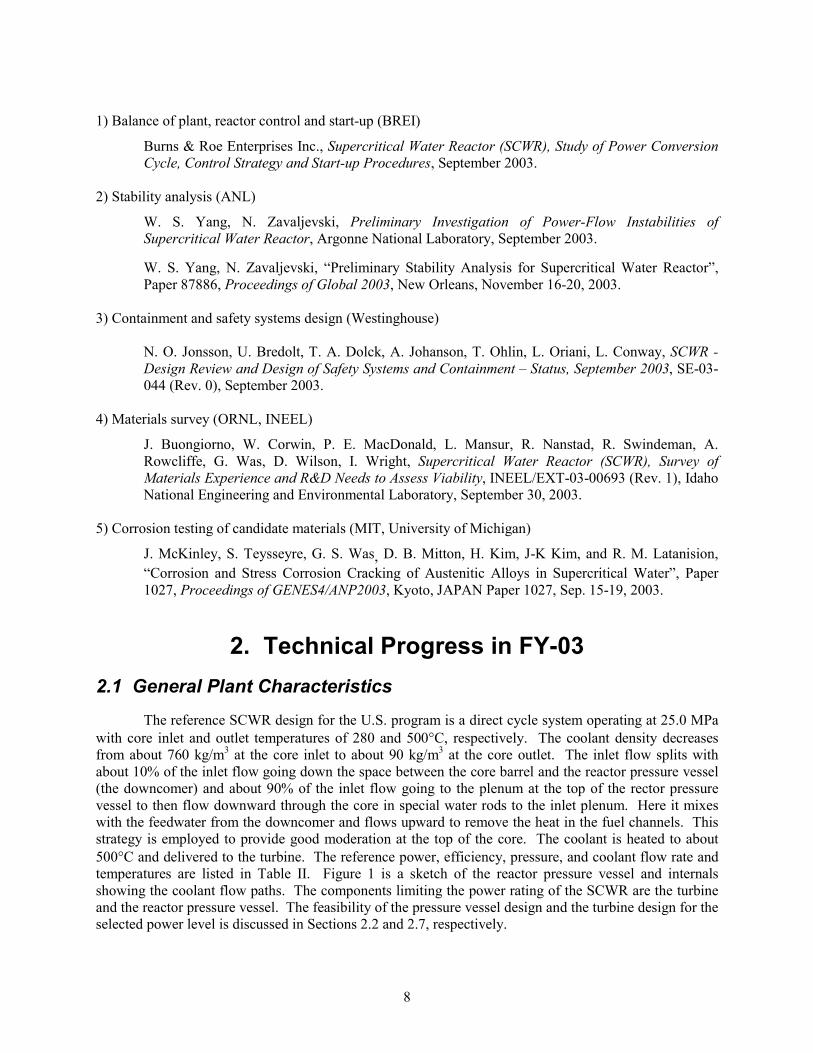
Table III. The SCWR RPV parameters.
Parameter Value Type PWR with top CRDs Height 12.40 m Material SA-508 Operating/design press. 25.0/27.5 MPa Operating/design temp. 280/371°C # of cold/hot nozzles 2/2 Inside diameter of shell 5.322 m Thickness of shell 0.46 m Inside diameter of head 5.352 m Thickness of head 0.305 m Vessel weight 780 t Peak fluence (>1 MeV) <1020 n/cm2
10
Figure 2. Dimensions of the SCWR RPV showing the inlet and outlet nozzles (lengths in inches).
The SCWR RPV was sized by Westinghouse to meet the requirements of the ASME code, Section
III, Class I, NB-3324, and its structural design was verified both at Westinghouse and INEEL with detailed three-dimensional finite-element analyses including the effect of penetrations, vessel weight and thermal stresses. The RPV is vertically supported below all four nozzles.
The expected radiation damage to the vessel over the 60-yr lifetime is within typical PWR range due to a similar downcomer width and somewhat lower power density. Nevertheless radiation embrittlement issues will be minimized by controlling the use of sensitizing materials (Cu, P) in the weld regions and by fabricating a single ring forging for the active core region to avoid the need for circumferential welds in that region. Also, a surveillance program will be implemented to monitor the evolution of the thick sections of the vessel.
Note that the SCWR RPV is beyond current manufacturing capabilities in the U.S. The beltline-
region ring forging is 4.3 m corresponding to the active core height. This slightly exceeds the height of the largest SA 508 forged rings made to date (about 4 m) by Japan Steel Works (JSW) for the ABWR. However, JSW has indicated that they should be able to build longer and thicker forgings with some modest changes in their equipment. JSW is limited by the total weight of any given forging or about 600 t, which is much higher than the weight of the 4.3-m long SCWR RPV ring forging (about 285 t).
ORNL has assessed the possibility of using advanced (higher-strength) materials to reduce the thickness and weight of the SCWR RPV. These include A508 Grade 4N Class 1 and a developmental steel, 3Cr-3WV. Use of these steels would allow for more than a 30% reduction in shell thickness, which could significantly reduce the fabrication costs, assuming a material cost not much higher than SA-508’s. However, significant additional mechanical property data would be needed for these materials to allow for their inclusion in the ASME code, and irradiation effects data for all relevant mechanical properties would be required for licensing.

11
Outstanding issues for the SCWR RPV include (i) the design of the thermal sleeve, which has not been performed yet, but is key to the RPV feasibility, (ii) formal confirmation of the manufacturing capabilities for the beltline ring forging at JSW or other manufacturers, (iii) maintenance of through-thickness mechanical and chemical properties during fabrication, and (iv) monitoring of flaw density in the very thick shell, which will be a challenge especially at weld locations.
2.3 Core and Fuel Assembly Design and Materials Selection The reference SCWR core design is shown
in Figure 3. The relevant dimensions are listed in Table IV. The core has 145 assemblies with an equivalent diameter of about 3.9 meters. The average power density is about 70 kW/L (or 30% higher than BWRs and 35% lower than PWRs) with a total target power peaking factor of about 2.0. The average and peak linear heat generation rates are similar to typical LWR values. The estimated core pressure drop is also comparable with typical LWR pressure drops and inlet orifices are used to adjust the flow to each assembly based on its expected power.
Table IV. Reference reactor core design for the U.S. Generation-IV SCWR.
Parameter Value Number of fuel assemblies 145 Equivalent diameter 3.93 m Core barrel ID/OD 4.3/4.4 m Axial/Radial/Local/Total Peaking Factor 1.4/1.3/1.1/2.0 (best estimate)
1.4/1.4/1.2/2.35 (safety analysis) Average power density 69.4 kW/L Average linear power 19.2 kW/m Peak linear power at steady-state conditions
39 kW/m
Core pressure drop 0.15 MPa Water rod flow 1659 kg/s (90% of nominal flow rate)
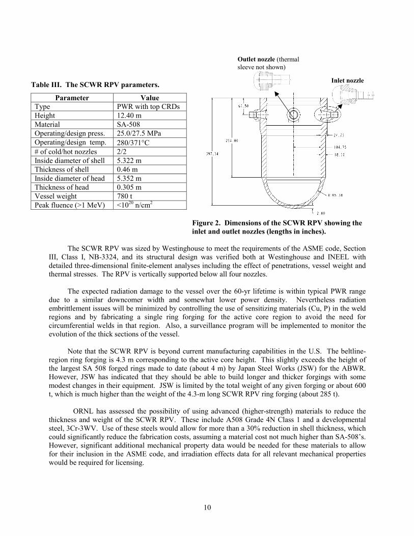
The reference SCWR fuel assembly design is shown in Figure 4 and the relevant dimensions are
listed in Table V. The fuel assembly has square water rods and an external duct. Analyses performed at the INEEL have shown that it may be necessary to insulate the water moderator boxes to retain a sufficient moderator density. The appropriate insulating material has not yet been determined. Figure 10 also shows the control rods inside 16 water moderator boxes, including the control rod thimbles. However, the control rod worth calculations are not complete and it may be desirable to change the number and/or size of the control elements, or it may be desirable to change the locations of the control elements. Also, it is assumed that there is one instrumentation tube in each assembly at the center fuel rod location. The number of the dimensions are tentative including the fuel bundle wall thickness and the inter-assembly gap size, and the fuel pin spacers have yet to be designed.
Downcomer
Fuel Assemblies
Core barrel
Reactor Pressure Vessel
Figure 3. Sketch of the reference SCWR core.
12
Water rod (×36) Fuel rod (×300)
Control rod (×16)
Instrumentation pin
Figure 4. The SCWR fuel assembly with water rods.
Table V. Reference fuel assembly design for the U.S. Generation-IV SCWR.
Parameter Value Fuel pin lattice Square 25×25 array Number of fuel pins per assembly 300 Number of water rods per assembly 36 Water rod side 33.6 mm Water rod wall thickness 0.4 mm (plus insulation if needed) Number of instrumentation rods per assembly
1
Number of control rod fingers per assembly
16
Control rod material B4C for scram, Ag-In-Cd for control Number of spacer grids 14 (preliminary estimate) Assembly duct thickness 3 mm (plus insulation if needed) Assembly side 286 mm Inter-assembly gap 2 mm Assembly pitch 288 mm
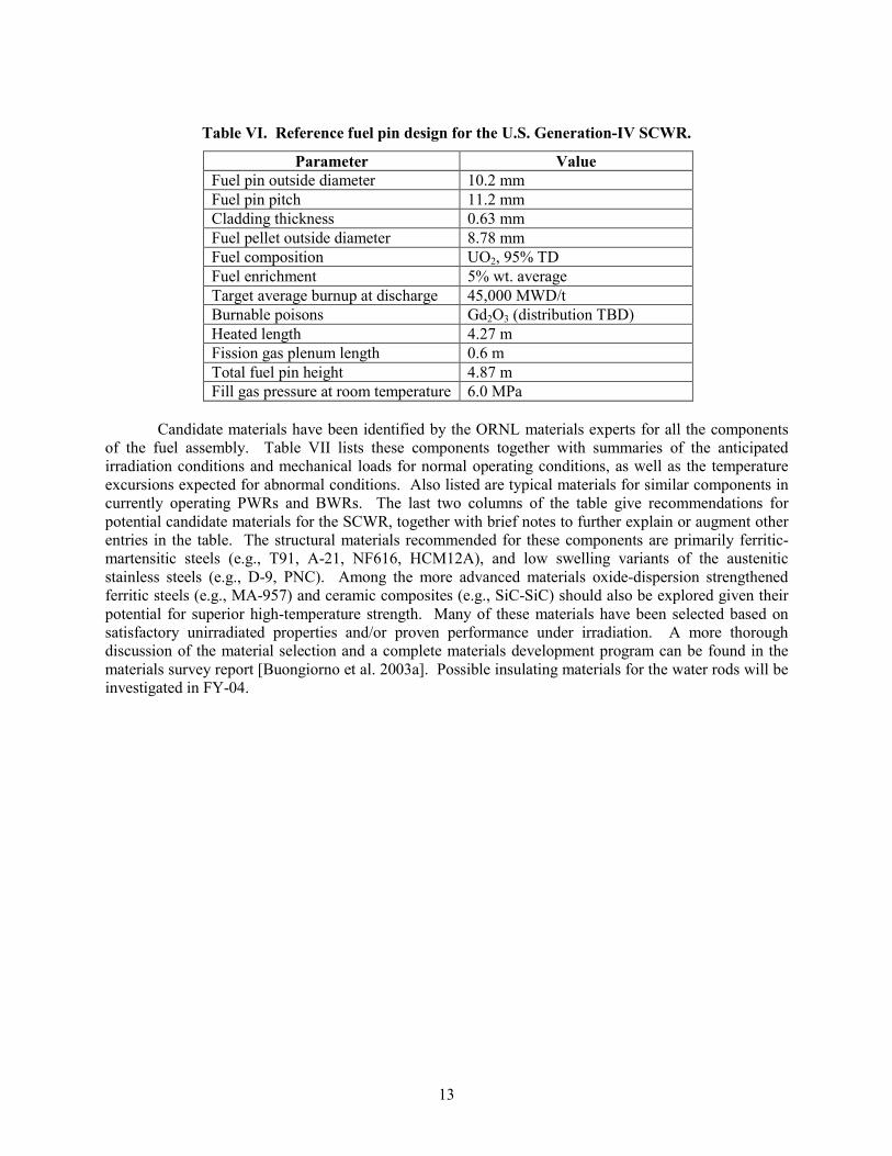
The reference fuel pin dimensions are listed in Table VI. The fuel pin dimensions are typical of
17×17 PWR fuel assembly pins, with the exception of the plenum length and fill pressure. Thermo-mechanical analysis of the SCWR fuel pin were performed at the INEEL with the FRAPCON code have shown that a higher fill pressure is needed to prevent buckling at beginning of life and a longer fission gas plenum is needed to limit the internal pressure at end of life. Also, to enhance coolant velocity and heat transfer, the fuel pin pitch is considerably smaller than the pitch used in LWRs. The U-235 enrichment, the Gd2O3 loading, and the fuel burnup are typical of the values used in high burnup LWR fuel, although their distribution within the fuel pin, within the fuel assembly and throughout the core are yet to be determined.
13
Table VI. Reference fuel pin design for the U.S. Generation-IV SCWR.
Parameter Value Fuel pin outside diameter 10.2 mm Fuel pin pitch 11.2 mm Cladding thickness 0.63 mm Fuel pellet outside diameter 8.78 mm Fuel composition UO2, 95% TD Fuel enrichment 5% wt. average Target average burnup at discharge 45,000 MWD/t Burnable poisons Gd2O3 (distribution TBD) Heated length 4.27 m Fission gas plenum length 0.6 m Total fuel pin height 4.87 m Fill gas pressure at room temperature 6.0 MPa
Candidate materials have been identified by the ORNL materials experts for all the components
of the fuel assembly. Table VII lists these components together with summaries of the anticipated irradiation conditions and mechanical loads for normal operating conditions, as well as the temperature excursions expected for abnormal conditions. Also listed are typical materials for similar components in currently operating PWRs and BWRs. The last two columns of the table give recommendations for potential candidate materials for the SCWR, together with brief notes to further explain or augment other entries in the table. The structural materials recommended for these components are primarily ferritic-martensitic steels (e.g., T91, A-21, NF616, HCM12A), and low swelling variants of the austenitic stainless steels (e.g., D-9, PNC). Among the more advanced materials oxide-dispersion strengthened ferritic steels (e.g., MA-957) and ceramic composites (e.g., SiC-SiC) should also be explored given their potential for superior high-temperature strength. Many of these materials have been selected based on satisfactory unirradiated properties and/or proven performance under irradiation. A more thorough discussion of the material selection and a complete materials development program can be found in the materials survey report [Buongiorno et al. 2003a]. Possible insulating materials for the water rods will be investigated in FY-04.

14
Table VII. O
perating conditions and candidate materials for the in-core reactor com
ponents of the SCW
R. A
ll components listed are
part of the replaceable fuel assembly.
N
ormal C
onditions Abnorm
al C
onditions C
urrent LWR
Materials
Com
ponent
Temperature 1
Peak D
ose 2
Loads 3 Tem
perature 4 PW
R
BW
R
Candidate SC
WR
M
aterials
Notes
Fuel cladding 280-620 ºC
15 dpa
∆P across cladding (com
pressive stresses up to 100 M
Pa), grid-cladding and fuel-cladding interactions
Up to 840 °C
for <30 sec
Zircaloy 4 Zircaloy 2
Fe-Ms, Low
-sw
elling S.S.
Spacer grids/w
ire wrap
280-620 ºC
15 dpa H
old the fuel pins together
Up to 840 °C
for <30 sec
Zircaloy 4, Inconel 718
Zircaloy 4, Inconel X750, 304 S.S.
Fe-Ms, Low
-sw
elling S.S.
Water rod boxes
280-300 ºC inner
280-500 ºC outer
15 dpa ∆P<0.1 M
Pa U
p to 700 °C for
<30 sec N
/A Zircaloy 2
Fe-Ms, Low
-sw
elling S.S., SiC
-SiC
May need to insulate.
Fuel assembly
duct 280-500 ºC
inner 280-300 ºC
outer 15 dpa
∆P<0.1 MPa
Up to 700 °C
for <30 sec
N/A
Zircaloy 4 Fe-M
s, Low-
swelling S.S.,
SiC-SiC
May need to insulate.
Control rod
guide thimble
280-300 ºC
15 dpa Low
hydraulic and therm
al stresses 280 - 300 °C
Zircaloy 4
N/A
Zircaloy 4, Zr-N
b alloy Zr alloy selected for superior neutron econom
y.
1. Peak temperatures in PW
Rs are 320-370 °C
2. D
esign estimates for typical high burnup LW
R
fuel 3. In addition, all reactor internals w
ill be subject to seism
ic and pipe break loads. 4 C
ondition II events only (LOC
As, LOFAs,
ATWSs are excluded)
Fe-Ms (Ferritic-M
artensitic) steels, e.g., T91 (9Cr-1M
o-V), A-21 (9Cr-TiC
mod), N
F616 (9Cr),
HC
M12A (12C
r), 9Cr-2W
VTa, MA-957.
Traditional low-sw
elling stainless steels, e.g., D-9 (14.5C
r-14.5Ni, 2M
o, Ti stab), PNC
~D-9
mod w
/P).

15
2.4 Vessel Internals Design and Materials Selection
The important reactor pressure vessel internals include the lower core support plate, the core former, the core barrel, the upper core support plate, the calandria tubes located immediately above the upper core support plate, the upper guide support plate, the hot nozzle thermal sleeve or insulation, and the control rod guide tubes. The location and approximate shape of most of these components is shown in Figure 1. All the reactor pressure vessel internals components will be designed for periodic replacement so that very high fluence loadings will not need to be considered.
Some of these components, including the lower core support plate and the control rod guide tubes in the upper head, will be subjected to normal PWR coolant temperature conditions and will be similar to the components typically used in PWRs. However, a number of the reactor pressure vessel internals, including the core barrel (or possibly the core former, depending on the design details), the upper guide support plate, the calandria tubes, and the reactor pressure vessel hot nozzle sleeve, will be in contact with coolant at the inlet temperature of 280°C on one side and the hot outlet coolant at a temperature of 500°C on the other side. Preliminary stress analyses performed at Westinghouse indicate that metal wall designs that are similar to those currently used in LWRs for those components cannot be used. Such a high temperature drop across those walls will cause the thermal stresses and deformations to be too large and/or cause too much heat to be transferred across the walls. For example, a simplified thermal stress analysis of the upper guide support plate was performed using a temperature difference of 220°C (396°F) and the Pro/Mechanica software. The result was that much of the structure will exceed the 3 Sm Primary + Secondary stress limit of Subsection NB of the ASME code as shown in Figure 5. Resolution of these issues may require new design features including special materials, insulation layers, and/or use of an insulating layer between double walls. Possible insulating materials for the vessel internals will be explored in FY-04. Some other reactor pressure vessel internals components, such as the upper core support plate, will be exposed to the outlet coolant at a temperature of about 500°C on all sides, and will not require insulation.
The size and shape of most of the reactor pressure vessel internals discussed above should be
similar to comparable components in a large Westinghouse designed PWR. However, it should be noted that the design of the calandria tubes that guide the flow of the moderator water through the hot region above the core and guide the control rods is not complete. There is a need to minimize the heat transfer surface area, and one way to do that is to combine the outside water moderator boxes into one channel in the region above the core.
Figure 5. Results of the preliminary thermal stress analysis of the upper guide support plate.

16
Table VIII. O
perating conditions and candidate materials for the core structural support reactor com
ponents of the SCW
R.
Norm
al Conditions
Abnormal
Conditions
Current LW
R M
tlsC
omponent
Temperature
1 Peak D
ose 2 Loads 3
Temperature
PWR
B
WR
Candidate SC
WR
M
aterials
Notes
Upper G
uide Support
(UG
S) plate
280 ºC upper
500 ºC low
er 0.021 dpa
Significant hydraulic and therm
al loads Low
er side at up to 700 °C
for <30 sec
304L S.S 304L S.S.
Advanced S.S., Fe-M
s M
ust insulate between the region
above the core (500 °C) and the
upper plenum (280 °C
) to limit the
thermal loads in the U
GS.
Calandria Tubes
280 ºC inner
500 ºC outer
(w/o
insulation)
0.021 dpa Significant hydraulic and therm
al loads 280 °C
inner 700 °C
outer N
/A N
/A Advanced S.S., Fe-M
s M
ust insulate to limit the heat
transfer from the coolant to the
moderator and control the therm
al loads in the calandria tubes.
Upper C
ore Support (U
CS)
plate
500 ºC
0.021 dpa Significant hydraulic. M
oderate thermal.
Up to 700 ºC
for <30 sec
304 S.S. 304, 304L, 316 S.S.
Advanced S.S., Fe-M
s The w
ater rod box penetrations m
ay cause some locally high
thermal stresses.
CR
guide tubes
280 ºC
0.00001 dpa Low
hydraulic. Low
thermal.
N/A
304 S.S. 304 S.S.
Advanced S.S., Fe-M
s, 304L M
ay want to use the sam
e material
as for the UG
S, UC
S, and calandria tubes
Lower core
plate 280-300 ºC
0.39 dpa
Significant hydraulic. Low
thermal.
Supports core.
N/A
304L S.S 304L S.S.
Advanced S.S, Fe-M
s, 304L M
ay want to use the sam
e material
as for the UG
S, UC
S, and calandria tubes
Core Form
er ~280-600 ºC
∼20 dpa 4
Significant hydraulic. H
igh thermal.
700ºC
304 S.S. N
/A Fe-M
s, Low-
Swelling S.S.
Must insulate either the core form
er or core barrel to control the therm
al loads in the barrel.
Core barrel or
shroud 280ºC
core region, 500 ºC
above core
3.9 dpa Significant hydraulic. H
igh thermal.
N/A
304L S.S 304L S.S.
Fe-Ms, Low
-Sw
elling S.S. M
ust insulate the core barrel above the core region and insulate either the core barrel or core form
er in the core region.
Threaded fasteners
280-500 ºC
< 4 dpa 5
316 S.S./C
W
304, 600, 316, 316L
Advanced S.S., IN
-718, 625, 690 The current design is an all w
elded core form
er and barrel.
1. Peak temperatures in PW
Rs are320-370 °C
2. D
esign estimates for 60y
3. All reactor internals will be subject to seism
ic and pipe break loads 4. Assum
ing the core former is replaced tw
ice over the 60-yr lifetim
e of the plant 5. ~ 50 dpa for baffle bolts and form
ers in PW
Rs. H
ere it is assumed that fasteners w
ill not be used in the high flux regions.
Fe-Ms (Ferritic-M
artensitic) steels, e.g., T91 (9Cr-1M
o-V), A-21 (9Cr-TiC
mod), N
F616 (9Cr), H
CM
12A (12Cr), 9C
r-2WVTa, M
A-957. Traditional low
-swelling stainless steels, e.g., D
-9 (14.5Cr-14.5N
i, 2Mo, Ti stab), PN
C ~D
-9 mod w
/P). Advanced stainless steels, e.g., H
T-UPS (~PN
C), AL-6XN
(20Cr-24N
i-6Mo-0.2C
u-0.2N), etc.

17
Materials recommendations for all vessel internals are reported in Table VIII. Again ferritic
steels and low-swelling stainless steels are recommended for the components more exposed to the neutron flux, while high-strength stainless steels and nickel-based alloys can be used in regions where low radiation damage is expected.
In FY-03 two traditional austenitic steels (304L and 316L) were tested at MIT and the University of Michigan for corrosion and stress-corrosion cracking (SCC) susceptibility in supercritical water. Although it is recognized that these alloys are not particularly promising because of their relatively poor irradiation stability and high-temperature strength, a large database for corrosion and SCC is available at LWR conditions, and it was deemed useful to compare that known behavior with their behavior in supercritical water. It was found that both alloys are susceptible to SCC (316L less so than 304L) in both deaerated and non-deaerated high-temperature (>400°C) supercritical water [McKinley et al. 2003]. Thus, these alloys cannot be used for high-temperature components in the SCWR. However, they could be used for components operating in the 280-350°C range (e.g., the lower core plate, the control rod guide tubes), given their satisfactory behavior in deaerated water at these temperatures.
2.5 Reactor Coolant System The reactor coolant system discussed in this section comprises (i) the feedwater lines from the
isolation valves to the RPV, and (ii) the steam lines from the RPV up to the second set of main steam isolation valves outside the containment. The balance of plant is discussed in Section 2.7. In the ASME Code terminology the feedwater and steam lines within the containment are Class 1 components, and any break they might experience is considered a loss-of-coolant accident (LOCA). The SCWR reactor coolant system was designed by BREI and has two feedwater lines and two steam lines (as opposed to four in a BWR of similar thermal power). The main parameters of the SCWR reactor coolant system are reported in Table IX.
Table IX. SCWR reactor coolant system parameters.
Parameter Value Number 2 Operating temperature 280°C Operating/design pressure 25/27.5 MPa OD/thickness 400 mm / 51 mm Fe
edw
ater
lin
es
Reference materials SA-106 Grade C (carbon steel) Number 2 Operating temperature 500°C Operating/design pressure 25/27.5 MPa OD/thickness 470 mm / 51 mm
Stea
m li
nes
Reference material P91 (9Cr-1Mo) or P92 (9Cr-2W)
The SCWR feedwater lines can likely use standard LWR materials such as carbon steels, perhaps clad with stainless steel if thus dictated by the water chemistry. The selection of suitable materials for the steam lines is more problematic. While the SCWR steam lines operate at temperatures and pressures that are well within the supercritical fossil plant experience, the direct application of fossil plant materials is not straightforward because of the ASME Code regulations. For example, Alloy 91 (P91) is used for fossil plant steam lines and is also approved for use in Subsection NH (high-temperature applications) of the ASME Section III (nuclear components), but its lifetime at temperature is limited by the Code to only

34 years vs. the intended 60 years of life in the SCWR plant. So either the steam lines are replaced after 34 years or the allowable lifetime for P91 in Subsection NH must be extended to 60 years. There are also some alternate (stronger and more corrosion resistant) materials that could be considered. For example, P92 (9Cr-2W) is an advanced ferritic steel also used in fossil-fired supercritical plant steam lines, and meets the requirements of B31.1 (non-nuclear applications), but would have to be qualified for Section III.
2.6 Containment The SCWR containment was designed by Westinghouse [Jonsson et al. 2003] and is a pressure-
suppression type containment with a condensation pool (essentially the same design as modern BWRs). Key containment parameters are listed in Table X. A three-dimensional isometric sketch of the SCWR containment is shown in Figure 6 and an axial cross-section with dimensions is shown in Figure 7. The dry and wet well volumes were calculated to limit the pressure build-up to typical BWR levels following a LOCA or a severe accident with core melting (hydrogen generation from cladding oxidation was considered in the calculations). The concrete floors were designed to withstand such loads. The condensation pool water inventory provides ample margin for residual heat removal and meets the requirement that active safety systems are not needed during the first 24 hours following an initiating event resulting in a severe accident. The blow-down pipes or vents are placed in the outer cylindrical walls due to lack of space in the inner cylindrical walls.
Table X. SCWR containment parameters.Parameter Value Dry well volume 5000 m3 Wet well gas volume 3300 m3 Wet well condensation pool volume
5640 m3
Blow-down area 18 m2 (~60 vents) Dry well maximum pressure 510 kPa Wet well maximum pressure 470 kPa Dry to wet well maximum pressure difference
300 kPa
Dry well temperature local (short time)
500°C
Dry well temperature global (short time)
350°C
Dry well temperature global (long time)
150°C
Wet well gas temperature 100°C Condensation pool temperature <100°C
18
Figure 6. SCWR pressure suppression pool type containment.
Compared to the advanced BWR containment designs, the SCWR containment drywell can be
reduced because:

19
•= The SCWR has only two steam and feedwater lines. •= The SCWR has a smaller diameter of the pressure vessel. •= The control rods enter the reactor pressure vessel from the top. Also, there are less control rod
drive installations needed and fewer areas needed for transportation of equipment. Also, installations for control rod drive maintenance are not needed below the pressure vessel.
•= There are no internal recirculation pumps.
On the other hand, the SCWR containment drywell volume is increased because of the high temperature fluid moving from the reactor to the turbine, since additional cooling and thermal expansion space are needed. Also, the concrete must accommodate higher temperatures during an accident. Furthermore the SCWR containment is lower because the pressure vessel is lower. However, this will tend to increase the diameter of the containment and will also lead to less space for connections and floorings. When all these effects are accounted for, the SCWR containment ends up being somewhat smaller than that of an advanced BWR of similar thermal power, and thus significantly smaller on a per unit electric power basis.
Figure 7. SCWR pressure suppression containment building.
Our interpretation of the Generation-IV goal of superior safety is that because the potential for
core damage in a SCWR is similar to traditional LWRs, enhanced safety is only possible if one can claim that the offsite consequences of a core damage accident are negligible. The European Utility Requirements statements regarding severe accidents and mitigation of their effects were adopted: “Core debris cooling. This can be achieved via a solidly founded technical demonstration for either in-vessel debris cooling or ex-vessel debris cooling.” The current SCWR design includes a core catcher under the

20
reactor pressure vessel, thus achieving ex-vessel retention. However, based on the power rating and vessel size of the SCWR, an alternative solution featuring in-vessel core debris cooling should also be possible. As already mentioned, the condensation pool is sized to provide a sufficient heat sink for decay heat in case of severe accident. This approach leads to a larger containment size, but simplifies the design of safety and mitigation systems. Other alternatives should be possible to provide the same grace period following a severe accident, e.g., a passive containment cooling system. It is difficult to judge the best solution at this point of the design, and it was, therefore, decided to proceed with this reference solution. Based on a critical review of the severe accident mitigation strategy, further reduction of the containment volumes will be explored in FY-04.
Outstanding issues for the SCWR containment include an evaluation of the consequences of the
high local temperatures following blow-down and verification that the safety systems can be accommodated within the containment.
2.7 Dynamic Analysis of the SCWR Reference Plant
2.7.1 Stability Analysis
Consistent with the U.S. NRC approach to BWR licensing, the licensing of SCWRs will probably require, at a minimum, demonstration of the ability to predict the onset of instabilities. This can be done by means of a linear analysis. Prediction of the actual magnitude of the unstable oscillations beyond onset, although scientifically interesting and relevant to beyond-design-basis accidents, will likely not be required for licensing and can be delayed to a second phase of the SCWR development.
Thermal-hydraulic and thermal-nuclear coupled instabilities were investigated at ANL2 [Yang and Zavaljevski 2003]. A frequency-domain linear stability analysis code was developed based on single-channel thermal hydraulics, one-dimensional fuel heat conduction, and point-kinetics models. The reactivity feedback coefficients were calculated with the WIMS-8 lattice code. Following the standard approach for BWR stability analysis, the system stability was estimated using the decay ratio, which is determined by searching the dominant root of the system characteristic equation directly in the complex plane. Preliminary stability analyses were performed for the reference SCWR concept. It was found that the core-wide in-phase oscillations would decay quickly at normal operating power and flow conditions. The estimated hot-channel decay ratios for thermal-hydraulic and thermal-nuclear coupled instabilities are 0.20 and 0.007, respectively, which are well below the limits traditionally imposed for BWR stability (0.5 and 0.25 for thermal and thermal-nuclear oscillations, respectively). Sensitivity studies showed that increasing the pressure loss coefficient of the inlet orifice increases the system stability, while increasing the coolant density feedback coefficient decreases it. Also the effect of the axial power profile was investigated and it was found that, compared to the cosine shape axial power profile, a uniform power profile improves stability, but a bottom-skewed profile decreases it slightly.
2.7.2 Preliminary Analysis of Key Transients and Accidents
Westinghouse and INEEL performed a critical review of the LWR abnormal events and their NRC classification with respect to the SCWR application. The objective was to identify potentially troublesome events on which to focus the R&D attention as early in the program as possible. The following four events were singled out:
2 Dr. Pradip Saha at MIT is also conducting SCWR stability analysis with internal funding. His results are consistent with ANL’s.

21
♦= Total loss of feedwater flow. Because the SCWR is a once-through direct cycle without coolant
recirculation, a loss of feedwater flow immediately causes a loss of core flow and results in rapid undercooling of the core.
♦= Turbine trip without steam bypass. The average coolant density is low in the SCWR core and pressurization events (such as the turbine trip without stem bypass or the accidental closure of the main steam isolation valves) result in significant positive reactivity insertion and increase in reactor power.
♦= Loss of feedwater heating. When a feedwater heater is lost, relatively cold water enters the core resulting in the insertion of positive reactivity. The difference between the behavior of a SCWR and a BWR is that the effect is expected to be more pronounced, because the feedwater is not mixed with hotter water before entering the core.
♦= Large break in the feedwater lines (or cold-leg large-break LOCA). Because the SCWR coolant path is once-through without recirculation in the vessel, an unmitigated large break in the feedwater lines results in coolant stagnation in the core and rapid overheating of the fuel.
Note that the first three events are classified by the U.S. NRC as moderate-frequency (Condition II)
events for LWRs and must not result in any significant damage to the fuel, while the large-break LOCA is classified as a rare event (Condition IV) and limited damage to the fuel is permitted.
Because at supercritical conditions the boiling crisis does not occur, the traditional CHF criterion to assess the margin to failure cannot be used. Maximum allowable cladding temperatures are specified instead for both transients (Condition II events) and accidents (Condition III and IV events). Note that a cladding temperature criterion (<1205°C, <2200°F) is also used for LWRs in the analysis of large-break LOCAs, and thus is adopted for the SCWR accidents as well3. The limit for transients is assumed to be 840°C, which is a reasonable value, but will have to be verified with fuel performance codes. The following limits are also assumed for the SCWR fuel, and are identical to those used in BWRs: no centerline melting under transient overpower, and radial-averaged fuel enthalpy (at any location in the core) below 0.711 kJ/g (170 cal/g) during transients and below 1.17 kJ/g (280 cal/g) during accidents.
A preliminary analysis of the SCWR response to the four events mentioned above was performed at the INEEL. The purpose of the analysis was to characterize the time constants of the system so that the required response times and capacities for various safety systems could be determined. The analysis was performed using a modified version of RELAP5-3D, specifically improved to support analysis of the SCWR. The improvements included changes of the water properties interpolations around the critical point, modification of the solution scheme in the supercritical region, and addition of heat transfer and wall friction correlations applicable to supercritical conditions. The RELAP5 model includes the average channel, the hot channel (with radial, axial and local power peaking factors of 1.4, 1.4 and 1.2, respectively, but without the other hot channel factors) and three core bypass paths; uses inlet orifices to minimize power/flow mismatches and boundary conditions to represent the feedwater and main steam systems; and calculates the transient reactor power with a best-estimate point kinetics model using reactivity feedback generated with the MCNP-4B code.
The effect of the main feedwater (MFW) pumps coastdown time, scram delay time and auxiliary feedwater (AFW) flow rate was evaluated for the total loss of feedwater. Figure 8 shows that the SCWR meets the transient peak cladding temperature criterion with the following assumptions: a MFW pump coastdown of 5 s, AFW flow is initiated at 4.25 s and corresponds to 15% of the initial MFW flow, the reactor scram signal is generated at 0.5 s, triggered by a 10% reduction in MFW flow, the control rods 3 However, note that this criterion may be conservative for the SCWR system, which does not use zirconium-based cladding.

22
begin moving 0.8 s later and are fully inserted 2.5 s later, the reactor pressure is assumed to remain constant due to the operation of turbine bypass valves. Thus, the SCWR will likely need an AFW system that is fast acting and of relatively high capacity; this will be a significant design challenge.
0 20 40 60 80 100Time (s)
300
400
500
600
700
800
900
Tem
pera
ture
(o C)
Reference designTransient limit
Figure 8. Peak cladding temperature during the loss of MFW flow event for the SCWR.
The analysis also showed that the turbine trip without steam bypass is fairly benign because the
high-capacity steam relief valves open quickly and prevent over-pressurization of the system, i.e., the inherent behavior of the SCWR is very similar to a BWR. However, the reactivity insertion is not as high as in the BWR because most of the moderation in the SCWR core is obtained from liquid coolant (in the water rods), which is not affected by pressurization. As a result the fuel is not overheated. The reactor scram, triggered by the turbine trip, quickly terminates the event.
The loss of feedwater heating is also benign as shown in Figure 9. The cladding and the fuel (not shown) are not overheated because of the lower temperature coolant and the Doppler feedback effect, respectively. The assumptions are as follows: the event is initiated by a 30°C step decrease in feedwater temperature (corresponding to the loss of the last heater on the high-pressure feedwater train), the MFW mass flow is held constant during the transient, scram is not assumed, and the turbine bypass valves are assumed to hold the reactor pressure constant.
0 50 100 150 200Time (s)
500
600
700
800
900
Tem
pera
ture
(o C)
Reference designTransient limit
Figure 9. The effect of a 30°°°°C step reduction in MFW temperature on the peak cladding
temperature.

23
As far as the cold-leg large-break LOCA is concerned, the calculations were performed without emergency core coolant and automatic depressurization systems to provide an indication of the time available for these systems to operate. A 100% feedwater line break is assumed. Scram is not needed as the reactivity feedback due to the decrease in moderator density is able to quickly shut down the reactor. No explicit modeling of the RPV-containment coupling is provided at this stage, so the pressure downstream of the break is set to atmospheric pressure. The main feedwater flow in the other feedwater line is ramped linearly to zero over 5 s. Check valves in the steam lines close quickly. The results are shown in Figure 10. The SCWR reaches the accident limit of 1205°C in about 25 s. As in other LWRs, this will require the definition of both a high-pressure (active or passive) injection system for initial mitigation plus a low-pressure (active or passive, with a depressurization plus gravity injection solution).
0 10 20 30 40Time (s)
400
600
800
1000
1200
1400
Tem
pera
ture
(o C)
Reference designAccident limit
Figure 10. The effect of a 100% feedwater line break on the peak cladding temperature.
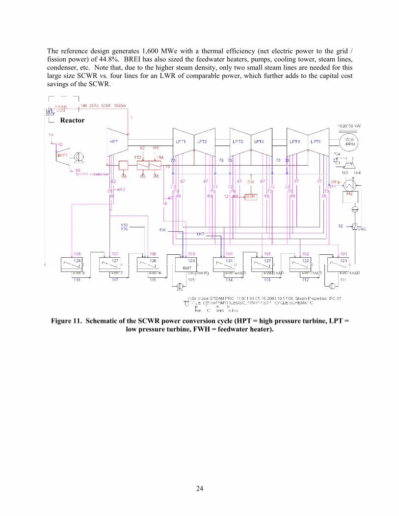
2.8 Balance of Plant (BoP) The reference SCWR system has a power conversion cycle that is very similar to a supercritical
coal-fired plant, with the boiler replaced by the nuclear reactor. BREI has performed a conceptual study of the power conversion cycle for the SCWR to identify an optimal configuration for the goals of thermal efficiency and electric power output maximization and capital cost minimization. Particular attention was also given to ensure that all components are either commercially available or within current design capabilities. The following trade-offs affecting the goals were considered: full vs. reduced speed of the turbine-generator module, single-shaft vs. multi-shaft arrangement of the turbine-generator module, steam-turbine-driven vs. motor-driven feedwater pumps. A schematic of the SCWR power conversion cycle is shown in Figure 11, while the operating conditions are reported in Table XI. The following design choices should be noted:
•= Reduced rotation speed, 1800 rpm •= Single-shaft turbine-generator •= One high-pressure/intermediate-pressure turbine (HPT/IPT) unit and three low-pressure turbine
(LPT) units with six flow paths •= Moisture separator reheater between the HPT/IPT and the LPTs •= Eight feedwater heaters raising the feedwater temperature to 280°C •= Steam-turbine-driven feedwater pumps operating at about 190°C •= Heat rejection in natural draft cooling towers
24
The reference design generates 1,600 MWe with a thermal efficiency (net electric power to the grid / fission power) of 44.8%. BREI has also sized the feedwater heaters, pumps, cooling tower, steam lines, condenser, etc. Note that, due to the higher steam density, only two small steam lines are needed for this large size SCWR vs. four lines for an LWR of comparable power, which further adds to the capital cost savings of the SCWR.
Reactor
Figure 11. Schematic of the SCWR power conversion cycle (HPT = high pressure turbine, LPT =
low pressure turbine, FWH = feedwater heater).

25
Table XI. List of pressures, temperatures, mass flow, and enthalpy at the numbered locations of Figure 11.
Stream p [bar] T [C] T [kg/s] h [kJ/kg]1 Throttle or initial condition outside ST 235 494 1722.47 3167.36 PIPT ahead of intercept valve 12 188 1130.63 2773.711 Condenser (LPT exhaust 0.05 33.1 782.36 2290.312 SSR Inlet 1.24 105.8 0.94 2616.514 After 2nd RH 12 363 149.69 3182.215 LPT Crossover 12 363 982.07 3182.240 Inlet stream of FPT 11.43 361.4 96.15 3179.960 Extr1 (or exh if only 1 group) of FPT 0.07 38.7 96.15 2410.462 Add / extr of ST group 2 70 313.3 265.4 289364 Add / extr of ST group 4 45 259.4 127.38 2805.365 Add / extr of ST group 5 23 219.6 75.74 2684.867 Add / extr of ST group 7 5.4 264.2 13.39 2989.368 Add / extr of ST group 8 2.5 179.2 6.82 2825.170 Add / extr of ST group 10 0.6 86 9.84 2585.172 Add / extr of ST group 12 0.13 51.1 3.33 2382.173 Add / extr of ST group 13 0.05 33.1 130.3 2290.382 Stream to GSC 0.83 0.83 N/A 0.38 2616.5101 Heating steam at FWH1 0.12 49.5 19.96 2379.8102 Heating steam at FWH2 0.58 85 59.06 2582.7103 Heating steam at FWH3 2.4 177.8 40.94 2822.8104 Heating steam at FWH4 5.18 262.8 80.32 2987105 Heating steam at FWH5 11.08 361.1 53.54 3179.9106 Heating steam at FWH6 22.05 217.4 75.74 2682.4107 Heating steam at FWH7 42.17 254.5 127.38 2803108 Heating steam at FWH8 67.11 309.6 157.45 2890.7111 Drain liquid at FWH1 0.12 49.5 200.94 207.3112 Drain liquid at FWH2 0.58 52.9 180.99 221.5113 Drain liquid at FWH3 2.4 87.8 121.93 367.7114 Drain liquid at FWH4 5.18 112 80.99 470.2115 Drain liquid at FWH5 11.08 184.4 1842.92 782.5116 Drain liquid at FWH6 22.05 195.6 588.98 832.7117 Drain liquid at FWH7 42.17 220 513.24 944118 Drain liquid at FWH8 67.11 256.3 385.86 1116.4121 Feedwater into FWH1 19.42 34.2 878.88 145122 Feedwater into FWH2 17.81 47.3 1079.83 199.6123 Feedwater into FWH3 15.55 82.2 1079.83 345.2124 Feedwater into FWH4 14.69 106.1 1079.83 446125 Feedwater into FWH5 11.08 150.5 1079.83 634.5126 Feedwater into FWH6 253.69 190 1842.92 819.2127 Feedwater into FWH7 253.13 214.4 1842.92 926.2128 Feedwater into FWH8 252.53 250.7 1842.92 1090.8142 Feed water leaving condenser 0.35 33.1 782.74 138.8143 Cooling water into condenser 3.74 17.7 30275.3 74.5144 Cooling water leaving condenser 2.51 31 30275.3 130.1145 Feed water into reactor 252.01 280 1842.92 1230146 Steam leaving reactor 246.75 499.7 1842.92 3169.6152 Heating steam of 1st RH 70 313.3 107.95 2893153 Drain of 1st RH N/A N/A 107.95 825.7154 Heating steam of 2nd RH 246.75 499.7 120.46 3169.6155 Drain of 2nd RH N/A N/A 120.46 1188.2156 Moisture separator drain N/A N/A 120.57 798.4201 Cooling tower inlet air N/A 20 32549.72 N/A204 Cooling tower exit air N/A 27.2 33201.16 N/A210 SSR to condenser 1.24 105.8 0.94 2616.5Valve Stem leak 1 => LPcrs N/A N/A 1.13 3167.3Valve Stem leak 2 => SSR N/A N/A 0.05 3167.3HPT LP leak 1 => FWH4 N/A N/A 0.67 2583.4HPT LP leak 2 => SSR N/A N/A 0.89 2583.4

26
Figurfromturbiphys
The feasibility of the 1,600-MWe turbine-generator was verified with various turbine vendors. BREI has generated a stage-by-stage model of the HPT/IPT and LPT demonstrating that the steam parameters at the turbine inlet (494°C and 23.4 MPa), the steam speeds in the LPT exhaust annulus (<225 m/s), the LPT blade lengths (52") and moisture content (<15%) are all within current standard available technology. Note that the overall size of the SCWR turbine generator is similar to a 1,300-1,500 MWe LWR turbine generator (see Figure 12) because the volumetric steam flow processed in the LPT is similar for both plants.
Candidate materials for all BoP components have been
identified by ORNL, and are reported in Table XII. Note that the SCWR builds extensively on the successful materials experience in supercritical fossil plants.
Table XII. Candidate alloys for the SCWR balance of plant.
Component Fossil SCWR
Steam lines P91 P92
P91 P92
Casing cast 0.5%CrMoV 1.25Cr-0.5Mo 2.25Cr-1Mo P122 (HCM12A)
cast 0.5%CrMoV
Valves cast 0.5CrMoV Cast P91 Cast mod P91+WCoNbB
cast 0.5CrMoV
Bolting 1%Cr-Mo-V Type 422: 12%Cr Nimonic 80A
1%Cr-Mo-V 12%Cr
Rotor & discs 1%Cr-Mo-V forged NiCrMoV A469 Class 8 NiCrMoV A470 Class 8 NiCrMoV A471 Class 8 Type 422: 12%CrMoV mod 12%CrMoV 9%Cr-Co-Mo-W-V-Nb-N-B
1%Cr-Mo-V Turbine
Blades forged Type 403: 12Cr Type 422: 12Cr
Type 403 Type 422
Tubes Carbon steel, duplex stainless steels, titanium
Carbon steel, stainless steels, titaCondenser
Body Carbon steel Carbon steel Demineralizer/deareator Carbon steel Carbon steel High and low pressure feedwater heaters
Carbon steel Carbon steel
Condensate and feedwater pumps
F304L F304L
e 12. A large LWR turbine generator,
[Logan and Roy 2003]. The SCWR ne generator is expected to be of similarical size.
Comments Based on fossil experience New alloy Current Developmental Current Developmental (EPRI) Developmental (VGB) Current Current Current Current, low-alloy, bainitic steels Currently used in Europe Developmental Current
duplex nium
Based on fossil experience where SCC on coolant side is an issue Based on fossil experience Based on fossil experience Based on fossil experience
Based on fossil experience

27
2.9 Control Strategy
BREI has reviewed the general characteristics, standards and regulations for the control system in existing nuclear power plants in view of the SCWR application. The SCWR presents several similarities and differences with the BWR and PWR systems that affect the control strategy. The BWR similarities are associated with the direct cycle with feedwater flow entering directly into the reactor vessel and steam flow going directly to the turbine. A balance between feed and steam is required to maintain the water inventory in the vessel. Also, soluble poisons such as boric acid cannot be used for reactivity control. The PWR similarities are associated with the high operating pressure, the single-phase conditions at the core outlet and a core outlet temperature that is a function of power and coolant flow. Unique aspects of the SCWR that influence the control concept include the elimination of the recirculation pumps, the low water inventory in the RPV, the large change in coolant density across the core, the absence of a coolant level under supercritical conditions.
The major systems to be controlled in the SCWR are the reactor coolant system, the feedwater
and condensate system, the steam system, and the turbine generator system. The main variables to be controlled include the reactor power, the core outlet temperature during supercritical pressure operation (e.g., during full power operation), the reactor pressure, the reactor level during subcritical pressure operation (e.g., during start-up) and the feedwater flow.
Assuming that the SCWR will be operated in a base load rather than a load follow manner, and
considering the general characteristics of the SCWR plant, BREI has made the following two recommendations for the SCWR control system:
♦= Control of the main reactor variables. The control rods accomplish the primary control of the
thermal power. The turbine control valve provides the control of the pressure, and the feedwater flow (i.e., the feedwater pumps) provides the primary control of the outlet temperature. The control of the coolant inventory in the vessel is accomplished by assuring that steam and feed flow are balanced while maintaining the correct core outlet temperature. The control logic for the main four variables is illustrated in Figures 13 through 16. A detailed discussion of the control strategy can be found in the report prepared by Burns and Roe [BREI 2003].
♦= Integrated control system approach. Rather than an approach in which higher functions such as
power or turbine valve control are in manual with lower level control loops in automatic, a coordinated control in which all functions are in automatic is proposed. The relatively small vessel water inventory, the nuclear/thermal-hydraulic coupling, the lack of level indication under supercritical conditions and the absence of recirculation flow makes control more challenging. Thus, the use of an integrated control would allow the system to anticipate changes and react accordingly.
An example of how the SCWR integrated control system will function is provided next. Assume
that the reactor is operating at 100% power and the operator decides to lower the power to 95%; then the following sequence will follow:
i. The operator dials in the new thermal power set point. ii. A signal is sent by the control system to the various control subsystems such as reactor power
control, feedwater control and pressure control. iii. The reactor power control system inserts the control rods. iv. The core thermal power decreases and the core outlet temperature decreases.

28
v. The feedwater pumps will reduce the feedwater flow to re-establish the nominal core outlet temperature.
vi. The steam flow will also decrease and thus will the reactor pressure. vii. The turbine control valve will close slightly to re-establish the nominal pressure.
viii. The system will stabilize at 95% power with a reduced feedwater flow and steam flow and with the nominal pressure and core outlet temperature set points re-established.
CRD Movement
Reactor Power Control
Thermal Power Setpoint
Core Thermal Power
Rx Power Error
Core Outlet Temp
Core Outlet Temp Setpoint
+
-
-
-
+
+
Core Outlet Temp Error
To Feed Water Flow Control
To Reactor Pressure Control
TCV or
TBVPosition
RPV PressureControl
Measured RPVPressure
RPV PressureError
Core Thermal Power
Core ThermalPower Setpoint
+
-
-
-
+
+
RX Power Error
To ReactorPower Control
RPV PressureSetpoint
MeasuredSteam Flow
Figure 13. SCWR power control logic. Figure 14. SCWR pressure control logic
CRDMovement
Reactor Power Control
Core Outlet Temp
-
+
Core Outlet Temp Error
Core Outlet Temp Setpoint
FeedWater
ElementControl
Feed Water Flow Control
Reactor Power Error
FW-Steam Mismatch Error
-
+
Feed WaterTemperature
Compensation
FeedWater
ElementControl
Feed WaterFlow Control
MeasuredSteam flow
FW-Steam Mismatch Error
Core Outlet Temp **
Core OutletTemp Setpoint *
+
-
-
-
+
+
Core Outlet Temp Error
To Reactor Power
MeasuredFeedwater
Flow
* This is RCS Level Setpoint subcritical
** This is RCS Level during operation
Figure 15. SCWR core outlet temperature control logic. Figure 16. SCWR inventory control logic.
2.10 Start-up Procedures and Related Equipment There are two general means of control used for once-through supercritical fossil plants. These
are constant pressure and variable pressure operation (VPO). Through the 1970’s most of the once-through supercritical units were controlled using constant pressure in the boilers. This was due to the fact that these units were predominately base-loaded and U.S. turbines achieved high efficiencies at reduced load by use of high-pressure control stages for partial arc admission (partial steam flow). Therefore the U.S. power generators had little interest in VPO. On the other hand, in Europe and Japan the use of VPO was quite common. Also, U.S. plants were being asked to cycle more frequently and during 1970’s

29
European turbine suppliers started to sell their turbines to U.S. utilities. With this European equipment the U.S. utilities became familiar with VPO and many adopted its practice for their once-through plants. Many plants built in the late 1970’s and 1980’s included provisions for VPO.
With constant pressure start-up the required components are a start-up turbine bypass, a flush
tank and pressure reducing valves. With VPO start-up the required components are a start-up turbine bypass, a steam water separator, drain valves and recirculation pumps. In fossil plants there are three major economic benefits of VPO, i.e., (i) ramping pressure with load reduces turbine life expenditure per cycle, (ii) when turbine temperature change limits unit ramp rate, VPO can allow more rapid load changes than can constant pressure, and (iii) VPO can significantly improve part load heat rate (i.e., thermal efficiency). However, since the SCWR will be a base-load plant these advantages from VPO are somewhat diminished, particularly the low-load heat rate improvements.
As discussed in Section 2.8, there are several variables to be controlled during the start-up and shutdown of the once-through SCWR. The SCWR will require a start-up system to ensure adequate reactor power control over a range of 0.1% to 100% power, adequate control of the reactor water inventory and maintenance of the core outlet temperature via reactor power and feedwater control systems. The system must allow for the warming of steam piping to the turbine and ensure that only dry steam is supplied to the turbine. Given these requirements the use of a hybrid VPO is attractive. The integrated control system being recommended for the SCWR will vary the pressure during start-up, but will do so in discrete steps with about three pressure set-points that will be established by the operator until supercritical-pressure operation is reached. This type of system can be classified as a VPO or sliding pressure approach. A flowchart of the needed sequence and procedures for both start-up and shutdown of the SCWR plant is provided in Figure 17. The procedures for the SCWR start-up will be similar to a LWR except for the transition to and from supercritical-pressure operation. A quantitative simulation of the SCWR start-up procedures including nuclear effects and sizing of the start-up equipment will performed by BREI in FY-04.

30
ELECTRICAL SYSTEM IN SERVICE
•= 125 / 250 V DC Power Supply •= Uninterruptable Power Supply •= High Voltage (Switchyard) •= Medium Voltage Power Supply •= 480 Volt Power Supply •= Vital AC Power Supply •= Emergency Diesel Generator
SUPPORT SYSTEMS
IN SERVICE •= Control/Service Air •= Domestic (Potable) Water •= Fire Protection •= Service Water •= Pretreatment •= Demineralized Water •= Auxiliary Cooling Water •= Closed Cooling Water •= Turbine Lube Oil •= Stator Cooling
ESTABLISHING CIRCULATING
WATER FLOW •= Start first Circulating Water Pump •= Start second Circulating Water Pump
CONDENSATE SYSTEM
ALIGNMENT •= Condensate Storage Tank •= Condensate Transfer System •= Condenser •= Condensate Polishing
ESTABLISHING CONDENSATE FLOW •= Start first Condensate Pump •= Start first Condensate Booster Pump •= Fill Deaerator
ESTABLISHING FEEDWATER
FLOW •= Align Water/Steam Separator •= Verify Turbine Bypass in service •= Start Motor Drive Feedwater Pump •= Verify flow established
ESTABLISHING SAFETY SYSTEM
•= Automatic Depressurization •= Low Pressure Injection
NUCLEAR HEATING
•= Pull Control Rods to achieve Criticality
•= Start Nuclear Heating •= Monitor Reactor Parameters
PRESSURIZATION
•= Increase system temperature and pressure using nuclear heating
•= Increase Feedwater flow as required
ESTABLISHING CONDENSER VACUUM AND CONDENSER STEAM DUMP
•= Establish Gland Seal Steam to Turbines •= Start Vacuum Pumps •= Place Turbine Bypass Valve in service to
maintain system pressure
STARTING FIRST TURBINE DRIVE FEEDWATER PUMP
•= Start Turbine Driven Feedwater Pump using steam from the Main Steam Header
•= Secure Motor Driven Feedwater Pump
TURBINE GENERATOR •= Admit steam to turbine •= Bring turbine to synchronizing speed •= Synchronize Generator •= Increase Reactor Power as required •= Increase system pressure as required •= Increase Generator output •= Verify Turbine Bypass Valve Closing •= Start Heater Drains Pump
SLIDING PRESSURE OPERATION
•= Increase system temperature using nuclear heating
•= Increase Feedwater flow as required •= Increase Generator output
TRANSITION TO SUPERCRITICAL
OPERATION •= Increase system temperature and pressure
using nuclear heating and feedwater flow •= Isolate Water/Steam Separator when
operating at Supercritical conditions
INCREASING PLANT LOAD •= Increase system temperature using
nuclear heating •= Increase Feedwater flow •= Increase Generator output •= Verify Turbine Driven Feedwater Pump
steam supply shifts to extraction steam •= Start second Condensate Pump •= Start second Condensate Booster Pump •= Start second Turbine Driven Feedwater
Pump
100 % LOAD STEADY STATE OPERATION
•= Monitor Plant Performance at full load conditions
DECREASING PLANT LOAD •= Decrease Generator output •= Decrease system temperature •= Decrease Feedwater flow
SECURING PUMPS
•= Secure first Turbine Driven Feedwater Pump
•= Secure first Condensate Booster Pump
•= Secure first Condensate Pump
TRANSITION SLIDING PRESSURE OPERATION
•= Align Water/Steam Separator •= Decrease Generator output •= Decrease system temperature •= Decrease Feedwater flow •= Verify Water/Steam Separator level when
Supercritical conditions no longer exist
DECREASING PLANT LOAD •= Decrease Generator output •= Decrease system temperature •= Decrease Feedwater flow •= Verify Turbine Driven Feedwater Pump
steam supply shifts to Main Steam
SECURING TURBINE GENERATOR •= Decrease Generator output to minimum •= Initiate a Turbine Generator Trip •= Verify Reactor shutdown •= Verify Turbine Bypass Valve maintains
system pressure
DEPRESSURIZING •= Start Motor Drive Feedwater Pump •= Slowly decrease system pressure using
Turbine Bypass Valve •= Secure Turbine Driven Feedwater Pump
COOL DOWN
•= Cool system by dumping steam to the condenser
•= When steam pressure is low secure Vacuum Pumps
•= Secure Seal Steam System
RESIDUAL HEAT REMOVAL •= Verify core temperature has stabilized •= Secure Motor Drive Feedwater Pump •= Secure Condensate Booster Pump •= Secure Condensate Pump
(a) Start-up (b) Shutdown
Figure 17. Start-up and shutdown procedures for the SCWR.

31
2.11 Coolant Activation (N-16) Because it is a water-cooled nuclear system with a direct thermal cycle, the SCWR shares with
the BWR the issue of coolant activation and transport of the coolant activation products to the turbine and balance of plant. Consistent with the BWR experience, the dominant nuclide contributing to the SCWR coolant radioactivity at full power is 16N, which is produced by an (n,p) reaction on 16O 4. The production and decay of 16N in the SCWR coolant circuit along with the shielding requirements imposed on the balance of plant were analyzed at the INEEL and compared with those in a BWR of similar thermal power rating [Fischer et al., 2003]. The 16N activity distributions in the SCWR and BWR with hydrogen water chemistry are shown in Figure 18. The 16N activities in the steam lines of the SCWR is significantly higher than that of the BWR (∼385 vs. ∼180 µCi/g) for the following four reasons:
♦= The coolant transit time in the SCWR core is about twice that of the BWR core, ♦= The neutron flux is higher in the SCWR because of the higher power density, ♦= The slow coolant pass in the water rods produces a significant 16N activity at the SCWR core
inlet, ♦= All the 16N generated in the SCWR core is sent to the steam lines because there is no
recirculation within the vessel.
A simple gamma attenuation model showed that the higher 16N activity in the SCWR results in shielding requirements only up to 12% higher than for the BWR with hydrogen water chemistry. However, because of the higher SCWR electric power, the specific shielding costs ($/kWe) associated with 16N are expected to be similar to or better than the BWR’s.
(a) BWR (with hydrogen water chemistry) (c) SCWR
Figure 18. 16N activity distribution in the BWR and SCWR.
4 Note that activated corrosion impurities and some released fission products may also be present in the SCWR coolant, but they were not considered in the study because their contribution to the coolant radioactivity under full-power operation is negligible compared with the radioactivity from coolant activation.

32
3. Program Management The Generation-IV SCWR R&D program is managed in the U.S. by the SCWR Product Manager, whose activities include:
1) Generation and maintenance of a reference U.S. SCWR plant design. The design was discussed in Section 2 above and is summarized in a master table, which is continuously updated and periodically distributed to all members of the U.S. team. This approach ensures that the research activities across different functional areas are directed toward the development of a coherent design.
2) Relationship with DOE-NE, which includes periodic reporting on technical progress and costs for
the SCWR activities in the U.S., as well as preparation of research plans for future SCWR activities.
3) Representation of the U.S. SCWR team in GIF, which includes membership in the GIF SCWR
steering committee and preparation of a GIF R&D plan to coordinate SCWR activities worldwide. In FY-03 the steering committee met four times, in Tokyo (Apr 2003), San Diego (Jun 2003), Mito (Jul 2003) and Kyoto (Sep 2003).
4) Promotion of periodic information exchange meetings to disseminate technical findings. In FY-
03 three such meetings have been organized with a broad international attendance in Washington D.C. (Nov 2002), Madison Wisconsin (Apr 2003), and Tokyo Japan (Sep 2003).
5) Promotion of the SCWR concept through the organization of technical sessions at major nuclear
engineering conferences. Also, in FY-03 the Product Manager held seminars on the U.S. SCWR activities at the following organizations: General Electric, Westinghouse, Texas A&M, MIT, Idaho State University, University of Wisconsin at Madison, the Ministry of Energy Technology and Industry (METI) of Japan, the conference of Japan nuclear utilities and vendors.
4. Other SCWR Activities in the U.S. Other non-Generation-IV SCWR activities in the U.S. include four NERI projects and two I-
NERI projects. While these projects have well-defined scope and budgets that pre-date the inception of the Generation-IV program, an attempt has been made to coordinate their activities with the Generation-IV activities, so that DOE-NE’s objective of assessing the feasibility of the SCWR concept can be pursued effectively. The NERI and I-NERI projects are briefly presented next; however much more information can be found in the progress reports that these projects produce quarterly and annually for DOE.
The first NERI project (01-001) is titled “Feasibility Study of Supercritical Light Water Cooled
Reactors for Electric Power Production”, is led by the INEEL, started in 2001 and includes Westinghouse, the University of Michigan, and MIT. Activities at INEEL and Westinghouse include the neutronic, thermal-hydraulic, and mechanical design of the SCWR fuel assembly, core and vessel internals. The reference design for this project is the one described in Section 2, but two other approaches eliminating the need for water rods have been explored, one based on the use of solid moderators (zirconium hydrides) and one based on small hexagonal fuel assemblies in which moderation is provided by the feedwater in the inter-assembly gap. As part of this project a new SCW loop was constructed at the University of Michigan to investigate the susceptibility of candidate structural alloys to stress corrosion cracking in supercritical water at various temperature, pressure, oxygen, pH and conductivity

33
conditions. A schematic of the Michigan loop is illustrated in Figure 19. Also an existing SCW loop is being used at MIT for general corrosion screening of candidate alloys (see Figure 20).
Figure 19. The SCW SCC loop at U-Michigan.
Figure 20. The SCW general corrosion loop at MIT.
A second NERI project (01-091) is titled “Supercritical Water Nuclear Steam Supply System:
Innovations in Materials, Neutronics and Thermal-Hydraulics”, is led by the University of Wisconsin at Madison and ANL, and also started in 2001. R&D activities include core and plant design with the emphasis on an innovative dual-spectrum core concept using a fast central region surrounded by a thermal annular region. Also, instability experiments are performed in a supercritical CO2 natural circulation loop (see Figure 21) and corrosion of surface-treated alloys is investigated in a SCW loop (see Figure 22).
Controller
Computer Effluent
DI Water
DI Water
Cool Down Heat Exchangers
Back Pressure Regulator
Autoclave
Heater
Preheater
PumpPump
Flow Measurement
Cooling WaterInstrumented
Tube
Lexan Shield
Thermocouples
Preheater
FlowFlow
Flow
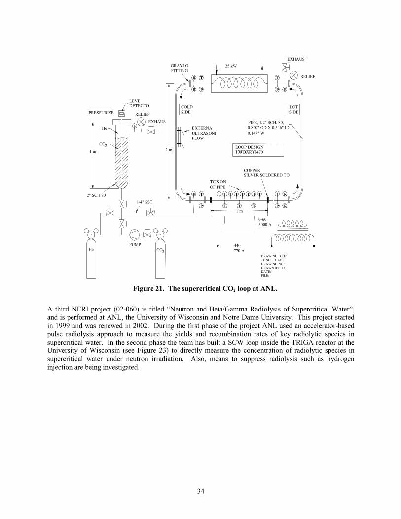
34
0-60 VAC5000 A
440 VAC770 A
TT TT TT TTTTTT TT TTTT
P
CO2
RELIEF
EXHAUST
PRESSURIZER
25 kW CHILLER
DRAWING: CO2 CONCEPTUAL DRAWING NO.: DRAWN BY: D. DATE: 4/11/02FILE:
( )
He
R T
P
R R
EXTERNALULTRASONICFLOW METER
R TT
P
T
P R
RELIEF EXHAUSTP He
CO 2 2 m
1 m
LEVELDETECTOR
1 m
PUMP
R
GRAYLOCFITTING
COPPER CONNECTIONSILVER SOLDERED TO PIPE
COLDSIDE
HOT SIDE
PIPE, 1/2" SCH. 80, SST0.840" OD X 0.546" ID X0.147" W
1/4" SST TUBE
LOOP DESIGN PRESSURE100 BAR (1470
i)
TC'S ON OUTSIDEOF PIPE
2" SCH 80 PIPE
T T T
Figure 21. The supercritical CO2 loop at ANL.
A third NERI project (02-060) is titled “Neutron and Beta/Gamma Radiolysis of Supercritical Water”, and is performed at ANL, the University of Wisconsin and Notre Dame University. This project started in 1999 and was renewed in 2002. During the first phase of the project ANL used an accelerator-based pulse radiolysis approach to measure the yields and recombination rates of key radiolytic species in supercritical water. In the second phase the team has built a SCW loop inside the TRIGA reactor at the University of Wisconsin (see Figure 23) to directly measure the concentration of radiolytic species in supercritical water under neutron irradiation. Also, means to suppress radiolysis such as hydrogen injection are being investigated.

35
TC1
3TC
TC2
5TC
4TC
48
47TC
TC
6TC
TC7
TC8TC
9
TC10TC
11TC15
TC34
TC33TC
32
TC31TC
30
16TC
17TC
18TC
19TC
20TC
21TC
25TC
28TC
29TC
TC38
TC43
TC42
TC41
TC40
TC39
TC26
TC27
TC12
TC13
14TC
L M S
22TC
TC23
24TC
35TC 36
TC 37TC
L
M
S
L M S
44TC
45TC
46TC
L
M
S
1EH
EH2
EH3
5EH
4EH
EH6
EH7
EH8
EH10
EH11
EH12
14EH
EH13
15EH
EH9
Cooler #1
Cooler #2
Heater #1
Heater #2
Hot coolant return
Coolant supply
Hot coolant return
Coolant supply
Remote operatedthrottle valves
Inline flow transducer(orfice type for temp issues??)
Primary coolant pump
To building drain
From building supply
TC52
51TC
50TC
49TC
Inline flow transducer
Remote operatedthrottle valve
54TC TC
53
55TC
Primary coolantsurge tank
Primary coolantpressure transducer
Remote operatedstop valve
Pressurized gas in
Remote operatedstop valve
Pressurized water in
EH16
TC56
Primary inlet
U-tube heat exchanger
Primary outlet
EH17
TC57
Manual Bleed Valve
Manual bleed valve
Water level transducer
Tap #2
Tap #1
Supercritical surge/makeup resevoir
High pressure (4Kpsi)water in
Manual stop valve
Manual stop valve
Surge pressure transducer
High pressure (4Kpsi)gas in
Coil in temp bath as throttle
Test water out for analysis
Tap #3
Experimental water inHPLC pumps
Remote operatedstop valve
Stop valvePort #4
Test section drainTest section
pressure transducer
Test sectionmechanical pressure gauge
Remote operatedstop valve
62.0
00
62.000
Figure 22. The SCW corrosion loop at U-Wisconsin.
section 1 section 2 section 3 section 4waterreservoir
HPLCpump
water bathH2O sampling
DAQ
Preheater
Irradiation volume
Graphitemoderator
Neutron shield
Pb gamma/betashielding
Heating section
Water shielding
89 cm94 cm
6 cm
48 cm92 cm
Figure 23. The in-pile SCW loop for radiolysis studies at U-Wisconsin.

The fourth NERI project (01-130) is titled “Fundamental Understanding of Crack Growth in Structural Components of Generation IV Supercritical Light Water Reactors” and is conducted at the Stanford Research Institute International. A test system for electrochemical and fracture mechanics studies in supercritical water was built as part of this project. Controlled-distance electrochemistry is used to measure the transport of ions or ionic defects in the oxide films on structural components made of stainless steels and nickel base alloys at supercritical temperatures. Ionic transport is then correlated with the susceptibility to cracking using fracture surface topography analysis of crack initiation and growth.
The first I-NERI (2003-008-K) is a collaboration with the Korean Atomic Energy Research Institute (KAERI) in South Korea, is titled “Developing and Evaluating Candidate Materials for generation-IV Supercritical Water Reactors”, started in 2003 and includes the ANL-West as the lead organization, the INEEL, the University of Michigan and the University of Wisconsin at Madison. The scope of this project includes a survey of commercial alloys for application to the SCWR, preparation of surface-treated coupons at the University of Wisconsin, testing of commercial and surface-treated alloys in the SCW loop at the University of Michigan, as well as mechanical testing of advanced alloys at INEEL.
The second I-NERI (2002-016-K) is also a collaboration with South Korea (Seoul National University and KAIST), is titled “Advanced Computational Thermal Fluid Physics (CTFP) and its Assessment for Light Water Reactors and Supercritical Reactors” and involves INEEL as the lead organization, Iowa State University, the University of Maryland, and Pennsylvania State University. This basic thermal fluids research applies first principles approaches (direct numerical simulation and large eddy simulation) coupled with experimentation (heat transfer and fluid mechanics measurements) to develop reliable computational tools for modeling of transport phenomena in supercritical fluids in complex geometries such as the core of a SCWR. The experimental work is performed at the INEEL’s Matched-Index-of-Refraction flow system while the development of the computational methods is performed at the universities.
There exists general
consensus that heat transfer data at prototypical SCWR flow and geometry conditions are urgently needed for reliable design of the SCWR core and safety systems. In FY-03 the INEEL performed the conceptual design and detailed cost estimate for a SCW loop that would allow collection of such data [Buongiorno et al. 2003b]. The INEEL loop is shown in Figures 24 and 25 and comprises a heater-bundle test section, preheaters, cooler, pump, accumulator and various auxiliary
Figure 24. Three-dimensional isometric view of the INEEL SCW heat transfer loop.
36

37
systems including a secondary cooling system, a deareator, a water supply system and water discharge tank.
Air Operated Control Valve (ACV)Block Valve (BKV)
Solenoid Valve (SV)
Pressure Relief Valve (PRV)
s
P
s
P
P
Check Valve (CKV)
Vacuum Breaker
PistonAccumulator
DeaeratorTank
Deaerator Pump
High PressureMakeup Pump
Primary Loop Pump0 - 0.42 kg/sec
Heat Exchanger
Quench Tank
Pressure Regulator (PR)P
P
Secondary LoopPump
280oC
Air Cooled Heat Exchanger
250o C
150oCs
oC550
Ball Valve (BLV)
Surge Tank
Fill Pump
s Vacuum Line
35 MPa NitrogenGas Supply
Vent
P
25 MPa
Preheater0 - 800 kW
Test Section
k0-350 W
Primary Loop
03-GA50036-70-16
Water SupplySystem
PressureRelief Lines
Figure 25. Simplified P&ID of the INEEL SCW heat transfer loop.
5. Conclusions
The research work during the first year of the Generation-IV SCWR program has established that:
1. The SCWR can make substantial use of existing LWR technology in the nuclear island. For example, the design and materials of the SCWR reactor pressure vessel and containment are similar to the PWR’s and BWR’s, respectively.
2. The SCWR can achieve high thermal efficiencies making extensive use of available supercritical
fossil plant technology in the balance of plant. For example, the materials and design of the power conversion cycle as well as the start-up and shutdown procedures and equipment can be drawn from fossil plants with only minor modifications.
3. Based on preliminary one-dimensional analyses, the SCWR appears to be stable with respect to
thermal-hydraulic and thermal/nuclear oscillations because of its relatively low coolant reactivity feedback coefficient.
4. The importance of the loss of feedwater as a key abnormal event has been recognized. The
design of a suitable high-pressure high-capacity fast-acting auxiliary feedwater system will be a major challenge in proving the viability of the SCWR.
5. Limited corrosion and stress-corrosion testing of traditional stainless steels in high-temperature
water has shown that finding materials that would perform satisfactorily in the SCWR
38
environment will be a challenge. However, classes of materials with promising mechanical properties and corrosion resistance have been identified and will be tested.
In summary, the basic assumptions contained in the Generation-IV Roadmap Report have been
confirmed and no new potential showstoppers have been found. The key feasibility issues for the SCWR remain the development of in-core materials and the demonstration of an adequate safety level.
6. References ♦= BREI, Burns & Roe Enterprises Inc., Supercritical Water Reactor (SCWR), Study of Power
Conversion Cycle, Control Strategy and Start-up Procedures, September 2003. ♦= BUONGIORNO, J., W. Corwin, P. MacDonald, L. Mansur, R. Nanstad, R. Swindeman, A.
Rowcliffe, G. Was, D. Wilson, I. Wright, Supercritical Water Reactor (SCWR), Survey of Materials Experience and R&D Needs to Assess Viability, INEEL/EXT-03-00693 (Rev. 1), Idaho National Engineering and Environmental Laboratory, September 2003(a).
♦= BUONGIORNO, J., K. G. Condie, G. E. McCreery, D. M. McEligot, M. E. Nitzel, J. E. O’Brien, The INEEL Heat Transfer Flow Loop for Development of Supercritical-Water-Cooled Reactors, INEEL/PRO-03-00565 (Rev. 1), Idaho National Engineering and Environmental Laboratory, June 2003(b).
♦= FISCHER, B., M. Przywojski, J. Buongiorno, “Nitrogen-16 Generation, Transport and Associated Shielding Requirements in the Supercritical-Water-Cooled Reactor”, submitted to Nuclear Technology, September 2003.
♦= GENERATION IV INTERNATIONAL FORUM (GIF), A technology roadmap for the Generation IV nuclear energy systems, GIF-002-00, 2002.
♦= KATAOKA, K. et al. “Development Project of Supercritical-water Cooled Power Reactor”, Proceedings of ICAPP-2002, Hollywood, Florida, June 9-13, 2002.
♦= JONSSON, N. O., U. Bredolt, T. A. Dolck, A. Johanson, T. Ohlin, L. Oriani, L. Conway, SCWR - Design Review and Design of Safety Systems and Containment – Status, September 2003, SE-03-044 (Rev. 0), September 2003.
♦= LOGAN, E. JR, and R. Roy, Handbook of Turbomachinery, 2nd edition, Marcel Dekker, Chapter 8, 2003.
♦= MCKINLEY, J., S. Teysseyre, G. S. Was, D. B. Mitton, H. Kim, J-K Kim, and R. M. Latanision, “Corrosion and Stress Corrosion Cracking of Austenitic Alloys in Supercritical Water”, Paper 1027, Proceedings of GENES4/ANP2003, Kyoto, JAPAN Paper 1027, Sep. 15-19, 2003.
♦= SPINKS, N. J. et al. “Thermo-economic Assessment of Advanced, High-Temperature CANDU Reactors”, Proceedings of the 10th International Conference on Nuclear Engineering (ICONE-10), Paper 22433, Arlington, Virginia, April 14-18, 2002.
♦= SQUARER, D. et al., High Performance Light Water Reactor (HPLWR), Summary report of the HPLWR Project, HPLWR D 13, European Commission, October 2002.
♦= YANG, W. S., N. Zavaljevski, “Preliminary Stability Analysis for Supercritical Water Reactor”, Paper 87886, Proceedings of Global 2003, New Orleans, November 16-20, 2003.