Embed Size (px)
Citation preview

SUPERIOR DESIGN BY NATURE
WALL FORM SYSTEM
IMPERIAL DESIGN GUIDE
Updated:
January 2017
ii
TABLE OF CONTENTS
Imperial Design Guide – Wall Form System
TABLE OF CONTENTS ................................................................................................................................. i
WARRANTY .................................................................................................................................................. iii
DISCLAIMER ................................................................................................................................................ iii
GENERAL ..................................................................................................................................................... 4
FLEXURAL DESIGN ..................................................................................................................................... 6
AXIAL DESIGN ............................................................................................................................................. 7
COMBINING FLEXURAL AND AXIAL LOADING......................................................................................... 9
DEFLECTION CONTROL ............................................................................................................................. 9
SHEAR DESIGN ......................................................................................................................................... 10
MINIMUM REINFORCEMENT.................................................................................................................... 11
COMPARISON OF DESIGN APPROACH AND TEST DATA .................................................................... 14

iii
Imperial Design Guide – Wall Form System
WARRANTY
We warranty our products to be free of defects and manufactured to meet published physical properties
when cured and tested according to ASTM, CSA and Nexcem Standards.
Under this warranty, Nexcem will replace any Nexcem Wall Form proven to be defective when applied in
accordance with written instructions and in applications recommended by Nexcem for this product.
All claims must be made within 1 (one) year of shipment. Absence of such claim in writing during this
period will constitute a waiver of all claims with respect of such products.
This warranty is in lieu of any and all other warranties expressed and implied.
DISCLAIMER
The recommendations, suggestions, statements and technical data in this technical guide are based on
Nexcem’s best knowledge. They are given for informational purposes only and are not to be
construed as overriding any requirements of any applicable building code.
Nexcem Inc. has no control over installation, workmanship, inspection, building conditions or applications.
There is no responsibility, expressed or implied warranty, either as to merchantability or fitness for the
parttheicular purpose, made as to the performance or results of an installation using Nexcem Wall Forms.
Structures built with the Nexcem Wall Forms should be designed and constructed in accordance with
applicable building codes. Nexcem material is not designed to carry any structural load other than
temporary concrete pressures that occur during construction. The concrete core within the Wall
Form is intended to be the primary load carrying material of the wall system. The design of the Nexcem
wall system should be conducted and reviewed by an engineer.
This document is not intended to override any applicable codes and practices that may be required in
local jurisdictions. The user should refer to applicable building code requirements when exceeding the
limitations of this document, when requirements conflict with the building code, or when an engineered
design is specified. This specification is not intended to limit the appropriate use of concrete or
construction not specifically prescribed. This document is also not intended to restrict the use of sound
judgment or exact engineering analysis of specific applications that may result in designs with improved
performance and economy.

4
Imperial Design Guide – Wall Form System
GENERAL
This guide is intended to convey the standard methods of structural design using the Nexcem Inc.
insulated concrete wall form system in conformance with the requirements of the acceptance criteria for
concrete wall systems as mandated by ICC Evaluation Service Inc. (ICC-ES). Acceptance criteria
guideline AC15 has been used for this report.
Design Assumptions
• The design method complies with current IBC, ASCE 7 and ACI 318 standards. No deviations from
this standard are anticipated. All assumptions listed in the standard are applicable (e.g., assumptions
about stress-strain relationships, acceptable material standards, etc.).
• Nexcem insulated wall formed concrete behaves as conventional reinforced concrete.
• The Nexcem material does not contribute to the design or strength of the wall system, thus, the
strength of the wall under axial, flexural and shear loading is calculated based on net section
properties (ratio of concrete filled wall to gross section properties). To account for this reduction in
area of concrete to the gross concrete section, additional strength reduction factors are noted below,
where applicable. There is a separate factor for shear resistance calculations to reflect the orthotropic
nature of the reinforced concrete wall created by the Nexcem system. This factor was determined
based on empirical testing in accordance with AC15.
Structural Design
Below is the recommended structural design method for reinforced concrete walls using the Nexcem Inc.
concrete wall form system, using the Load and Resistance Factor Design method described in the above
referenced codes and standards
Load Factors:
Refer to the IBC Section 1605 for information on load combinations, including earthquake loading.
Strength Reduction Factors:
Refer to ACI 318 Section 9.3.2 for information on strength reduction factors. Below are the applicable
factors typically used:
= 0.90 for Tension-controlled sections
= 0.65 for Compression controlled sections without spiral reinforcement
= 0.75 for Shear and Torsion

5
Imperial Design Guide – Wall Form System
Additional Resistance Factors:
Based on empirical testing and theoretical analysis, the following additional strength reduction factors
have been established:
D1 = 0.75 To be applied on top of all other concrete resistance factors for flexural, axial, out of plane
shear and deflection calculations. This factor is based on accounting for the percentage of
concrete area within the wall, when the Nexcem web portions are removed along the length
of a Nexcem wall. The Nexcem cores are spaced at 12” o/c and each core is nominally taken
as 9.4”. In other words, 9.4” of concrete resistance is present every 12” of wall length. This
results in a calculated reduction of 9.4 / 12 = 0.78. Testing has proven that a factor of 0.75 is
more accurate to reflect actual strength of the wall. The reduction from a theoretical value of
0.78 to 0.75 is due to the aggregrate response within wall as result of normal construction
methods that result in vertical cores not being precisely aligned.
D2 = 0.85 To be applied on top of all other resistance factors for concrete in-plane shear calculations.
This is based on full scale racking tests and is higher than D1 above because ACI 318
equations already approximate the portion of wall resisting shear loads by taking 80% of the
wall length. This is a conservative empirical assumption that results in a corresponding higher
D2 multiplier when theoretical values are compared against empirical testing. Combining the
D2 and the 0.8 from ACI equations result in a net lower resistance factor (0.8 x 0.85 = 0.68)
for in-plane shear resistance. This net lower D2 reflects the interaction of orthotropic nature
of the concrete grid within the Nexcem wall system (i.e. the angle of crack formation is less
than 45 degrees).

6
Imperial Design Guide – Wall Form System
FLEXURAL DESIGN
Design to resist pure flexural loading shall be in conformance with conventional reinforced concrete
design methods based on accepted practice and the stress-strain relationship of reinforced concrete.
Refer to ACI 318 for more information.
The bending strength of a concrete section is defined as follows:
Mn = D1 • • β1 • f’c • b • a • (d – 0.5 • a)
Where:
Mn = the nominal bending resistance of the reinforced concrete wall.
D1 = 0.75 (see design assumptions above).
= strength reduction factor as per ACI 318 (see above).
β1 = 0.85 for concrete with f’c ≤ 4000 psi (see ACI 318 for higher strength concrete)
f’c = the compressive strength of concrete.
b = the width of the compression block (typically the length of wall).
d = effective depth of section (typically the distance from the outside face of wall on the compression side
to the centroid of steel reinforcing).
a = the depth of the compression block to ensure ductile failure = (As • fy) / (D1 • β1 • f’c • b)
Where
As = the cross sectional area of tensile reinforcing steel.
fy = the yield strength of reinforcing steel.

7
Imperial Design Guide – Wall Form System
AXIAL DESIGN
Design to resist axial loading, with or without flexure, shall be in conformance with conventional reinforced
concrete design based on accepted practice and the stress-strain relationship of reinforced concrete.
Refer to IBC and ACI 318 for more information.
Axial Compression, Non-Slender, Without Flexure
The compressive resistance of a wall section is defined as follows. The use of this formula is allowed by
ACI 318,
Pn = D1 0.8 • • [ 0.85 • f’c • (Ag – As) + fy• As]
Where:
Pn = the factored compressive resistance of the reinforced concrete wall.
= strength reduction factor (see above).
Ag = the gross cross section concrete area.
f’c = the compressive strength of concrete.
As = the cross sectional area of tensile reinforcing steel.
fy = the yield strength of reinforcing steel.
D1 = Nexcem modification factor for axial-flexural strength = 0.7 (see design assumptions above).
Axial Compression With or Without Flexure, Slender
General assumption: it is anticipated that a wall built with the Nexcem Inc. concrete wall form system with
be designed assuming structurally pinned ends at all intermediate supports (i.e., floor levels, foundation,
roof level, etc.), and never in a sway frame condition. Therefore
Klu/r ≤ 34 – 12 • (M1/M2)
Reduces to:
Klu/r ≤ 34
Since M1 = M2 = 0 (no end moments on wall). Therefore, slenderness will be considered for all wall
sections where the effective length divided by the radius of gyration of the section (Klu/r) exceeds or
equals 34.

8
Imperial Design Guide – Wall Form System
Minimum Flexural Loading:
Regardless that there may be no anticipated applied flexural loading on the wall, a minimum bending
moment due to eccentric loading shall be applied to the wall section for design purposes using the
following formula:
Mmin = Pu • (0.6 + 0.03 • h)
Where:
Mmin = the minimum allowable factored bending moment.
Pu = the factored applied load on the wall section.
h = the height of the concrete section in the direction of bending (i.e., concrete thickness of wall).
Slender walls under axial loading will be designed for combined axial and flexural loading assuming
flexural loading that is the greater of the bending moment resulting from the minimum eccentric loading
defined above, and for second order effects using the Moment Magnifier Method as defined in ACI 318,
summarized as follows:
Mc = δns • M2
Where:
Mc = the magnified bending moment, including second order effects.
M2 = the greater of the minimum eccentric bending moment noted above, or the factored moment due to
applied loads.
δns = is the moment amplification factor, calculated as follows:
δns = cP
uPmC
75.01 ≥ 1
Where:
Cm = 1 (typical for walls with transverse loads between supports)
Pu = factored axial load at eccentricity, must be ≤ φ Pn
Pc = critical load, i.e., Pc = 2
2
)( ukl
EI

9
Imperial Design Guide – Wall Form System
Where, EI = d
gc IE
1
15.0
and,
Ec = Young’s modulus for concrete
Ig = the moment of inertia of the gross concrete wall section
βd = the ratio of factored dead load to the total factored axial load.
COMBINING FLEXURAL AND AXIAL LOADING
Flexural and axial compressive loads shall be combined by conventional analysis, with due consideration
for interaction of bending moment and compressive forces in the wall section, considering pure bending,
pure axial and balanced strain conditions. Interaction diagrams for any Wallform can be generated using
the same equations and factors identified above for flexural and axial strength of a given section. Axial-
flexural interaction is beyond the scope of this design guide, however, interaction diagrams for specific
Nexcem Wallform configurations (product type, concrete strength, rebar configuration) are available on
request.
DEFLECTION CONTROL
Deflection of the Nexcem Inc. concrete wall form system under applied lateral load shall be limited to a
maximum allowable deflection of wall span divided by 180, or L/180. This deflection limitation shall
include both immediate and long term deflection (see below).
Immediate deflection shall be calculated using conventional structural analysis techniques, using the
following stiffness formula:
Stiffness = D1 • Ec • Ie
Where:
Ec = 57,000 cf ' (in psi) for normal weight concrete.
Ie = The effective moment of inertia, or,
Ie = cr
a
crg
a
cr IM
MI
M
M
33
1
Where,

10
Imperial Design Guide – Wall Form System
Mcr = the cracking moment of the concrete section, or Mcr =
t
gr
y
If
cr ff '5.7 (psi)
yt = distance from the centroid of concrete to the extreme fiber in tension.
Ma = the applied moment at the stage deflection is computed
Icr = the moment of inertia of a cracked section with reinforcing steel transformed to equivalent concrete.
Long term deflection shall be calculated, where applicable, by the following:
'501
Where:
= 2.0 (assumes a sustained load period of 5 years or more).
ρ’ = ratio of reinforcing steel to gross section area.
SHEAR DESIGN
Design to resist out of plane and in plane shear loading, shall be in conformance with conventional
reinforced concrete design based on accepted practice and the stress-strain relationship of reinforced
concrete. Refer to ACI 318 for more information.
Out of Plane Shear
Out of plane shear design shall be in accordance with IBC and ACI 318. Thus, for out of plane shear, the
wall must be designed to satisfy the following:
Vn ≥ Vu
Where:
Vu = factored applied shear load.
Vn = factored shear resistance of the concrete wall section.
Vn = • (Vc + Vs)
It is not anticipated that shear reinforcement will be typical for out of plane loading for the Nexcem Inc.
concrete wall form system, thus, the above equation reduces to:
Vn = • Vc

11
Imperial Design Guide – Wall Form System
This is only appropriate for out of plane loading, which uses excludes slabs (thus out of plane walls) from
minimum shear reinforcing when Vu exceeds one half of φVn. Thus, it is only necessary to ensure the
factored shear capacity of plane concrete be greater than the factored applied out of plane shear loading.
Vc shall be computed for out of plane shear as follows:
dbfV cc '2 D1
In Plane Shear
In plane shear design shall be in accordance with ACI 318, with the following modifications
Vn ≥ Vu
Where:
Vu = the factored applied shear load.
Vn = factored shear resistance of the concrete wall section.
Vn = (Vc + Vs) if Vu ≤ Vc
or
Vn = (0.20 Vc + Vs) if Vu > Vc
Vc shall be computed for in plane shear as follows:
hdfV cc '2 D2 (modified ACI 11.9.5)
Where d shall be taken as the 0.8 times the length of the wall or 0.8 times the depth of the wall section in
shear (e.g., the wall acting as a lintel over an opening).
D2 = 0.85 To be applied on top of all other resistance factors for concrete in-plane shear calculations.
This is based on results of the full scale racking tests and is higher than D1 above because
ACI 318 equations already approximate the portion of wall resisting shear loads by taking
80% of the wall length. This is a conservative empirical assumption that results in a
corresponding higher D2 multiplier when theoretical values are compared against empirical
testing. Combining the D2 and the 0.8 from ACI equations result in a net lower resistance
factor (0.8 x 0.85 = 0.68) for in-plane shear resistance. This net lower D2 reflects the
interaction of orthotropic nature of the concrete grid within the Nexcem wall system (i.e. the
angle of crack formation is less than 45 degrees).

12
Imperial Design Guide – Wall Form System
For in plane shear, minimum shear reinforcement is required where Vu exceeds one half of Vc. ACI 318
allows that this minimum reinforcing be provided through the minimum wall reinforcing requirements,
which will be defined in the next section. Thus, we are only concerned with calculating the required shear
reinforcing where Vu exceeds Vn. The strength of this added shear reinforcement is calculated as
follows:
Vs =
2s
dfA yv
Where:
Av = the area of shear reinforcement within distance s2.
d = 0.8 L
L = Length of the wall.
s2 = spacing of shear reinforcement along the height of the wall
Stiffness / Deflections
Deflection due to lateral load (in plane shear), is a well known parameter that can be calculated for
normal concrete sections/walls, etc, based on the well known equations. Also, it is known that shear
deflection is a function that varies linearly in relation to wall dimensions (height, length, thickness)
For a normal cantilevered rectangular shear wall:
Deflection due to lateral load on a rectangular = AG
LP
4.02.1
Where:
P = Lateral Load
Le = 0.4x L
L = Length of shear wall
A = Effective area of wall in shear (core width x Le)
G = Shear Modulus = E/(2x1.15)
E = Youngs Modulus = 18.275 (f’c / 10)1/3 (SI)
The above values for E and G are more precise than that calculated from ACI equations. These more
precise values are used in order to more accurately isolate the geometric affects of the Nexcem material
present within the wall. For design, ACI equations for E and G are acceptable and will provide more
conservative deflection (i.e. greater deflections).
In the case of a Nexcem wall, the cross section of the wall is different in vertical section as compared to
horizontal section. The effective area, stiffness, and moment of inertia for Nexcem walls will be different
from that for monolithic walls, but the fundamental linear relationship will remain. All differences between
the Nexcem and a monolithic rectangular section are encompassed within the Le factor = 0.4 x L. This Le
should be used in all deflection equations parameters (see analysis on stiffness).
13
Imperial Design Guide – Wall Form System
MINIMUM REINFORCEMENT
All walls built with the Nexcem Inc. concrete wall form system shall be reinforced in conformance with all
applicable design requirements noted above, but will have minimum reinforcement as follows:
Minimum ratio of vertical reinforcing area to gross concrete area = 0.0012
Minimum ratio of horizontal reinforcing area to gross concrete area = 0.0020

14
Imperial Design Guide – Wall Form System
COMPARISON OF DESIGN APPROACH AND TEST DATA
This section is intended to meet the requirements of section 3.3.2 of ICC Evaluation Service Inc.
acceptance criteria guideline AC15.
Flexural:
Below is the summary table for flexural loading tests on a 3 core standard Nexcem Inc. 8” wall form
(WF20). This table has been taken from test report “Nexcem Axial-Flexurial Test Report” (report
included elsewhere). Refer to this report for further information, including test setup, sample preparation,
etc.
Reinforcing Specimen Maximum Load (kN) Maximum Moment (kNm)
1-15M 1 10.78 4.38
2 11.40 4.64
3 10.79 4.39
3-15M Average 11.0 4.5
1 34.52 14.04
2 31.37 12.76
3 34.43 14.00
Average 33.4 13.6
Table 2: Flexural Test Program Results
36” Reinforced Concrete Wall Form w/ 1 – 15M Vertical Bar
Sample Characteristics:
h = 4.72” (120mm)
As = 0.31 in2
d = 2.36 in
b = 36 in
f'c = 2908 psi (20 MPa)
fy = 58000 psi (400 MPa)
D1 = 0.75
Therefore, using the approach shown for Flexural Design above:

15
Imperial Design Guide – Wall Form System
Mr = D1 • β1 • φ • f’c • b • a • (d – 0.5 • a)
Since we are comparing actual test values to theoretical calculations, no strength reduction factor is used,
i.e., φ = 1.
Thus Mr = Multimate = D1 • β1 • f’c • b • a • (d – 0.5 • a)
Where:
a = (As • fy) / (β1 • f’c • b • D1)
= (0.31 • 58000)/(0.85 • 2908 • 36 • 0.75)
= 17980 / 66738.6
= 0.269 in.
Therefore,
Multimate = D1 • β1 • f’c • b • a • (d – 0.5 • a)
= 0.75 • 0.85 • 2908 • 36 • 0.289 • (2.36 – 0.5 • 0.269)
= 3.32 ft•k
Multimate = 4.52 kN•m
Average test value = 4.52 kN•m.
Therefore, theoretical value and test derived correspond exactly.
36” Reinforced Concrete Wall Form w/ 3 – 15M Vertical Bar
Sample Characteristics:
h = 4.72” (120mm)
As = 0.93 in2
d = 2.36 in
b = 36 in
f'c = 2908 psi (20 MPa)
fy = 58000 psi (400 MPa)
D1 = 0.75
16
Imperial Design Guide – Wall Form System
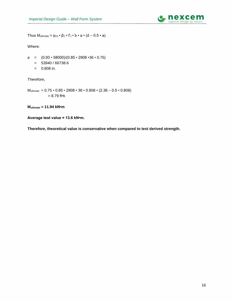
Thus Multimate = D1 • β1 • f’c • b • a • (d – 0.5 • a)
Where:
a = (0.93 • 58000)/(0.85 • 2908 •36 • 0.75)
= 53940 / 66738.6
= 0.808 in.
Therefore,
Multimate = 0.75 • 0.85 • 2908 • 36 • 0.808 • (2.36 – 0.5 • 0.808)
= 8.79 ft•k
Multimate = 11.94 kN•m
Average test value = 13.6 kN•m.
Therefore, theoretical value is conservative when compared to test derived strength.

17
Imperial Design Guide – Wall Form System
Axial - Flexural:
Below is the summary table for axial - flexural loading tests on a 3 core standard Nexcem Inc. 8” wall form
(WF20). This table has been taken from test report “Results of the Flexural and Axial Performance of
the Nexcem Insulated Concrete Form Test Program” (report included elsewhere). Refer to this report
for further information, including test setup, sample preparation, etc.
Reinforcing Eccentricity
(mm)
Specimen Maximum Load (kN)
1-15M 60 1 148.6
60 2 142.2
60 3 133.3
60 Average 141.3
3-15M 60 1 186.2
60 2 167.5
60 3 160.3
60 Average 171.4
Part of Table 3: Axial-Flexural Test Program Results
36” Reinforced Concrete Wall Form w/ 1 – 15M Vertical Bar, Axially Loaded with 60mm Eccentricity
From the test data: average applied axial load at failure = 141.3 kN = 31.77 kips. The weight of the wall
above the buckling point (mid height) = 150 pcf • 0.4 feet • 3 ft • 4 feet • D1 = 0.540 kips.
Therefore:
P = 31.77 + 0.420 = 32.30 kips
Eccentricity = 60mm, = 2.362 inches = 0.197 feet. Therefore, the applied bending moment =
M = 32.30 • 0.197 = 6.36 ft• k > Mn
δns = cP
uPmC
75.01 ≥ 1

18
Imperial Design Guide – Wall Form System
δns = )8.122(75.0
3.321
1
= 1.54 ≥ 1
δns M = 6.36 x 1.54 = 9.7 ft• k > Mn
Strength Interaction (Test Series 1)
0
50000
100000
150000
200000
250000
300000
350000
0 2000 4000 6000 8000 10000 12000 14000
Moment (lb-ft)
Axia
l L
oad
(lb
s)
Interaction Envelope
Design Envelope
Maximum Uncracked Moment
Failure Load (Magnified Mu, Pu)
Wall Type:
Wall Thickness:
Concrete Core Thickness:
Vertical Reinforcement:
Horizontal Reinforcement:
8" R8
8" (nominal)
4.72"
1 - 15M placed in centre of wall
none
c =
ec =
f'c =
s =
fy =
0.0035
1
60 ksi
1
2908 psi
Note that resistance factors φc and φs have been set to unity to compare ultimate theoretical strength to
ultimate test results. From the calculation (which is identical to the design approach described above),
the resultant from combined axial and flexural loading at failure is just inside the interaction curve, which
is a smoothed approximation of the true interaction design envelope

19
Imperial Design Guide – Wall Form System
36” Reinforced Concrete Wall Form w/ 3 – 15M Vertical Bar, Axially Loaded with 60mm Eccentricity
From the test data: average applied axial load at failure = 171.4 kN = 38.53 kips. The weight of the wall
above the buckling point (mid height) = 150 pcf • 0.4 feet • 3 ft • 4 feet • D1 = 0.540 kips.
Therefore:
P = 38.53 + 0..540 = 39.07 kips
Eccentricity = 60mm, = 2.362 inches = 0.197 feet. Therefore, the applied bending moment =
M = 39.07 • 0.197 = 7.69 ft• k
δns = cP
uPmC
75.01 ≥ 1
δns = )8.122(75.0
1.391
1
= 1.74 ≥ 1
δns M = 7.69 x 1.74 = 13.4 ft• k > Mn
20
Imperial Design Guide – Wall Form System
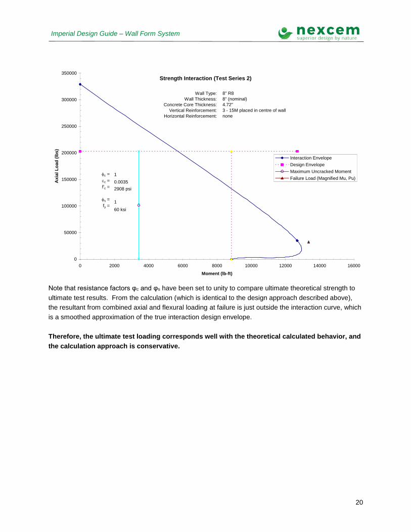
Strength Interaction (Test Series 2)
0
50000
100000
150000
200000
250000
300000
350000
0 2000 4000 6000 8000 10000 12000 14000 16000
Moment (lb-ft)
Axia
l L
oad
(lb
s)
Interaction Envelope
Design Envelope
Maximum Uncracked Moment
Failure Load (Magnified Mu, Pu)
Wall Type:
Wall Thickness:
Concrete Core Thickness:
Vertical Reinforcement:
Horizontal Reinforcement:
8" R8
8" (nominal)
4.72"
3 - 15M placed in centre of wall
none
c =
ec =
f'c =
s =
fy =
0.0035
1
60 ksi
1
2908 psi
Note that resistance factors φc and φs have been set to unity to compare ultimate theoretical strength to
ultimate test results. From the calculation (which is identical to the design approach described above),
the resultant from combined axial and flexural loading at failure is just outside the interaction curve, which
is a smoothed approximation of the true interaction design envelope.
Therefore, the ultimate test loading corresponds well with the theoretical calculated behavior, and
the calculation approach is conservative.
21
Imperial Design Guide – Wall Form System
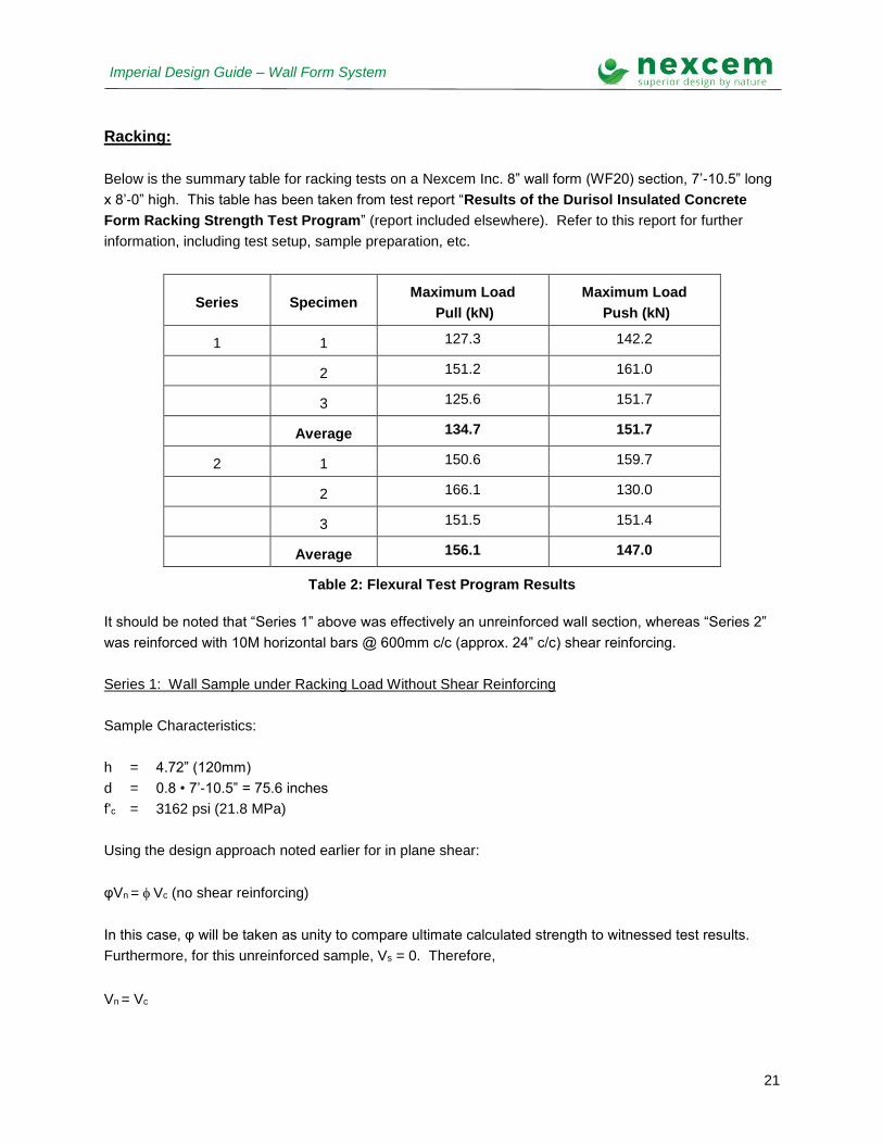
Racking:
Below is the summary table for racking tests on a Nexcem Inc. 8” wall form (WF20) section, 7’-10.5” long
x 8’-0” high. This table has been taken from test report “Results of the Durisol Insulated Concrete
Form Racking Strength Test Program” (report included elsewhere). Refer to this report for further
information, including test setup, sample preparation, etc.
Series Specimen Maximum Load
Pull (kN)
Maximum Load
Push (kN)
1 1 127.3 142.2
2 151.2 161.0
3 125.6 151.7
Average 134.7 151.7
2 1 150.6 159.7
2 166.1 130.0
3 151.5 151.4
Average 156.1 147.0
Table 2: Flexural Test Program Results
It should be noted that “Series 1” above was effectively an unreinforced wall section, whereas “Series 2”
was reinforced with 10M horizontal bars @ 600mm c/c (approx. 24” c/c) shear reinforcing.
Series 1: Wall Sample under Racking Load Without Shear Reinforcing
Sample Characteristics:
h = 4.72” (120mm)
d = 0.8 • 7’-10.5” = 75.6 inches
f'c = 3162 psi (21.8 MPa)
Using the design approach noted earlier for in plane shear:
φVn = Vc (no shear reinforcing)
In this case, φ will be taken as unity to compare ultimate calculated strength to witnessed test results.
Furthermore, for this unreinforced sample, Vs = 0. Therefore,
Vn = Vc
22
Imperial Design Guide – Wall Form System
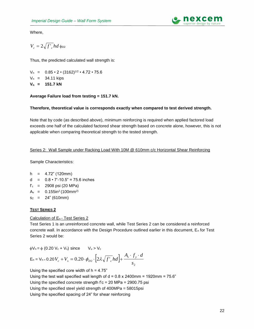
Where,
hdfV cc '2 D2
Thus, the predicted calculated wall strength is:
Vn = 0.85 • 2 • (3162)1/2 • 4.72 • 75.6
Vn = 34.11 kips
Vn = 151.7 kN
Average Failure load from testing = 151.7 kN.
Therefore, theoretical value is corresponds exactly when compared to test derived strength.
Note that by code (as described above), minimum reinforcing is required when applied factored load
exceeds one half of the calculated factored shear strength based on concrete alone, however, this is not
applicable when comparing theoretical strength to the tested strength.
Series 2: Wall Sample under Racking Load With 10M @ 610mm c/c Horizontal Shear Reinforcing
Sample Characteristics:
h = 4.72” (120mm)
d = 0.8 • 7’-10.5” = 75.6 inches
f'c = 2908 psi (20 MPa)
Av = 0.155in2 (100mm2)
s2 = 24” (610mm)
TEST SERIES 2
Calculation of En - Test Series 2
Test Series 1 is an unreinforced concrete wall, while Test Series 2 can be considered a reinforced
concrete wall. In accordance with the Design Procedure outlined earlier in this document, En for Test
Series 2 would be:
Vn = (0.20 Vc + Vs) since Vu > Vc
En = Vn = 0.20 2
2 '220.0s
dfAhdfVV
yv
cDsc
Using the specified core width of h = 4.75”
Using the test wall specified wall length of d = 0.8 x 2400mm = 1920mm = 75.6”
Using the specified concrete strength f’c = 20 MPa = 2900.75 psi
Using the specified steel yield strength of 400MPa = 58015psi
Using the specified spacing of 24” for shear reinforcing

23
Imperial Design Guide – Wall Form System
Using the specified factor for normal density concrete
En = 0.20 x 0.85 x[2 x 1 x (2900.75)1/2 x 4.75mm x 75.6] + [0.155 x 58015 x 75.6] / 24
En = 3575.8 + 28325.8 = 34901.6 lbs = 155.25 kN for Test Series 2
Average Failure Load obtained from testing = 159.1 kN.
Therefore, theoretical value is conservative when compared to test derived strength.


![Team Eccentric[1]](https://img.pdfslide.net/doc/110x75/577d27cd1a28ab4e1ea4dfc9/team-eccentric1.jpg)