Embed Size (px)
Citation preview

FORM #4530.03-090402 PRINTED IN U.S.A. PAGE 1 OF 13
Superlift 5” lift system for 1994- 2001 DODGE RAM 3/4-TON 4WD PICKUP
INSTALLATION INSTRUCTIONS INTRODUCTION Installation requires a professional mechanic. Prior to beginning, inspect the vehicles steering, driveline, and brake systems, paying close attention to the suspension link arms and bushings, anti-sway bars and bushings, tie rod ends, pitman arm, ball joints and wheel bearings. Also check the steering sector-to-frame and all suspension-to-frame attaching points for stress cracks. The overall vehicle must be in excellent working condition; repair or replace all worn parts. Read instructions several times before starting. Be sure you have all needed parts and know where they install. Read each step completely as you go. NOTES:
• Welding is required. Refer to steps 11 and 20.
• Rear lift is sold separately and includes separate instructions.
• An arrow on diagrams indicates which direction is toward the front of the vehicle.
• A foot-pound torque reading is given in parenthesis ( ) after each appropriate fastener.
• Do not fabricate any components to gain additional suspension height.
• Prior to drilling or cutting, check behind the surface being worked on for any wires, lines, or hoses that could be damaged.
• After drilling, file smooth any burrs and sharp edges.
• Prior to operating a torch or saw, protect any heat-sensitive components located in the immediate area by covering them with a water-saturated cloth. Most undercoating are flammable but can be extinguished using a water-filled spray bottle. Have a spray bottle and an ABC rated fire extinguisher on hand.
• Paint or undercoat all exposed metal surfaces.
• Prior to attaching components, be sure all mating surfaces are free of grit, grease, undercoating, etc.
• A factory service manual should be on hand for reference.
• Use the check-off box “” found at each step to help you keep your place. Two “” denotes that one check-off box is for the driver side and one is for the passenger side. Unless otherwise noted, always start with the driver side.

FORM #4530.03-090402 PRINTED IN U.S.A. PAGE 2 OF 13
PARTS LIST … The part number is stamped into each part or printed on an adhesive label. Identify each part and place the appropriate mounting hardware with it. PART NO DESCRIPTION NEW ATTACHING HARDWARE (Qty.- if more than one) (Qty.- if more than one)
01-146 ......................... (2) coil spring, front 55-21-4530................... (2) upper link ............................... (8) bushing half (4) 3/4” x 2.65” sleeve 55-02-4530................... (2) lower link ................................ (4) bushing half (2) 3/4” x 2.375” sleeve 55-03-4530................... link arm drop bracket, .................. (4) 12mm x 40mm bolt driver side (1) 12mm x 110mm bolt (4) 12mm SAE flat washer (2) 12mm USS flat washer (5) 12mm nyloc nut (1) 3/4” x 2.375” sleeve 55-04-4530................... link arm drop bracket, .................. (4) 12mm x 40mm bolt passenger side (1) 12mm x 110mm bolt (4) 12mm SAE flat washer (2) 12mm USS flat washer (5) 12mm nyloc nut (1) 3/4” x 2.375” sleeve 55-22-4530 .................. track bar bracket .......................... (1)18mm x 70mm bolt (1) extra thick flat washer (1) 18mm tapered lock nut (1) 1/2” x 2-1/2” bolt (1) 1/2” nyloc nut (1) special half washer 55-09-4530................... vacuum hose relocation ............... (1)1/4” x 1” bolt bracket (1)1/4” SAE flat washer (1)1/4” nyloc nut 55-10-4530................... (2) brake hose relocation ............. (2)1/4” x 1” bolt bracket, front (2)1/4” SAE flat washer (2)1/4” nyloc nut 1-14-4505..................... (4) triangle reinforcement wedges 55-11-4530................... brake hose relocation .................. 1/4” x 1” bolt bracket, rear 1/4” SAE flat washer 1/4” nyloc nut

FORM #4530.03-090402 PRINTED IN U.S.A. PAGE 3 OF 13
01-4005 ....................... pitman arm 1994-1999 OR 01-4006 ....................... pitman arm 2000-2001
55-09-4505 .................. upper shock plate, ........................ (1) 1/2” X 1” bolt driver side (1) 1/2” nyloc nut (1) travel limiting strap 55-10-4505 .................. upper shock plate, ........................ (1) 1/2” X 1” bolt passenger side (1) 1/2” nyloc nut (1) travel limiting strap 85304........................... (2) shock absorber, front .............. (2) shock boot*, yellow (2) hardware pack and cable tie *(Note: Shock boots, if desired, purchased separately) 85154........................... (2) shock absorber, rear ............... (2) shock boot, yellow (2) hardware pack and cable tie 0034............................. Superlift badge ............................. alcohol wipe pad 00461........................... decal, "Warning To Driver"
FRONT DISASSEMBLY 1) PREPARE VEHICLE... Place vehicle in neutral. Raise front of vehicle with a jack and secure a jack stand beneath
each frame rail, behind the lower trailing arms. Ease the frame down onto the stands, place transmission in low gear or “park”, and chock rear tires. Position a jack so that it supports, but does not raise, the front axle. Remove front tires.
2) FRONT SHOCK BRACKETS… Open the hood and remove the upper shock nuts and retainers on each side. Also remove
the 3 retaining nuts for the upper shock brackets and remove the brackets. Remove the lower shock retaining hardware and pull the shock up through the coil tower
under the hood. Save all hardware for reuse. 3) TRACK BAR AND DRAG LINK… Disconnect the track bar at the axlehousing, then remove the bolt that attaches the bar to the
frame. Save all hardware for reuse. Remove the factory steering stabilizer. Separate the drag link from the pitman arm and let hang. Remove the pitman arm retaining
nut, then separate the pitman arm from the steering sector shaft using a puller tool. Save all hardweare for reuse.

FORM #4530.03-090402 PRINTED IN U.S.A. PAGE 4 OF 13
4) ANTI-SWAY BAR… On each side, unbolt the anti-sway bar links from the axlehousing, then unbolt the anti-sway
bar from the frame. Flip the bar upside down so that the ends of the bar step up instead of down and reinstall on the frame in the factory position.
5) COIL SPRINGS… Carefully lower the front axle until the coil springs become loose. Remove the coils, rubber
insulators, and tower ring. Save the rubber insulators for reuse. NOTE: Use caution when lowering the front axlehousing to avoid damaging the brake lines,
vacuum lines, and front driveshaft. Pry the factory bumpstops from their mounts on the frame using a large screwdriver or pliers
and discard. 6) SUSPENSION LINKS… Cam bolts attach the lower suspension links to the front axle housing. Paint or scribe
alignment marks on each cam bolt and axle bracket so the bolts can later be returned to their original position.
Detach the upper and lower suspension links from the axle and the frame Save all hardware
for reuse. FRONT ASSEMBLY
7) LOWER LINKS… Lubricate the supplied bushing halves and sleeves and install them in the Superlift lower
links (#55-02-4530). Connect a lower link (#55-02-4530) to
the axle using the factory cam bolts, then to the frame using the factory hardware. These bolts should be installed from the outside. Be sure to position the link so that the zerk fittings are easily accessible for vehicle service. Do not fully tighten at this time.
8) LINK ARM DROP BRACKETS… [DIAGRAM 2] Test-fit the link arm
drop brackets (#55-03-4530 driver side and #55-04-4530 passenger side) on the axlehousing. Take one of the supplied 12mm bolts and check to see if the upper holes on the sides of each factory axle bracket (there are two holes per side) are large enough for the bolt to pass through. If not, drill the holes out to 1/2”.

FORM #4530.03-090402 PRINTED IN U.S.A. PAGE 5 OF 13
[DIAGRAM 1] Drill out the lower hole
on the sides of each factory axle bracket to 1/2”. This hole should be drilled from the outside, and the bit should pass through both sides of the axle bracket as shown.
[DIAGRAM 2] Position the supplied
3/4” x 2.375” sleeve inside the factory axle bracket and over the middle holes according to the diagram. Install the supplied 12mm x 110mm bolt with in the lower hole, through the sleeve, with the supplied thick 1/2” washers on both sides. Install a 12mm nyloc nut, but do not tighten at this time.
Install the supplied 12mm x 40mm
bolts, washers, and nyloc nuts in the remaining holes of the “03” and “04” brackets (2 per side). Place a washer under each bolt head, and each head should face the outside of the vehicle.
Torque the 110mm bolts (52-55) and the 40mm bolts (73-77). 9) UPPER LINKS… Lubricate the supplied bushing halves and sleeves and install them in the Superlift upper
links (#55-21-4530). On each side, slide the front
eye of the upper link far enough into the axle bracket to start the rear eye in the factory frame mount. Be sure to position each link so that the zerk fittings can be easily accessed for service. Attach the rear eye using the factory hardware, but do not tighten at this time.
Line up the front link eye in
the “03” and “04” brackets. Position one end of a supplied limiting strap on each factory upper link bolt, then install the bolt from the outside. Do not tighten at this time.

FORM #4530.03-090402 PRINTED IN U.S.A. PAGE 6 OF 13
10) VACUUM HOSE AND ELECTRICAL PLUG RELOCATION… [DIAGRAM 3] Locate the metal vacuum line that runs along the passenger side frame rail.
This line is attached to a rubber hose that connects to the vacuum actuator valve on the differential. Remove the metal line’s retaining screws and attach one end of the furnished vacuum line drop bracket (#55-09-4530) to the frame rail using one of the original screws. Carefully reform the metal line as necessary and attach it to the lower end of the “09” bracket using the supplied 1/4” x 1” bolt, washer, and nyloc nut (8).
Unplug the electrical line at the vacuum
actuator valve and release the line’s plastic retaining clip on the valve bracket. Reconnect the electrical line to the valve.
NOTE: If additional slack is needed for
the electrical line when the installation is complete, remove the line from the top of the crossmember and relocate it to the bottom of the crossmember. The line’s retaining clips can be reused.
11) TRACK BAR BRACKET… [DIAGRAM 4] Prior to installing the
track bar bracket, remove the bolt clamp that holds a steel brake line from the crossmember. Carefully push the line up and out of the way approximately 2 inches.
[DIAGRAM 5] Position the track
bar drop bracket (#55-22-4530) against the factory track bar mount to get an idea where the drop bracket will make contact with the original mount. Closely examine the factory mount to be sure its surface is smooth where it makes contact with the Superlift bracket. Some heavy-duty models have a reinforcement plate welded to the mount that MUST be ground smooth. Also check the fit of the gusset on the “22” bracket that contacts the bottom of the frame for later welding (see diagram 7 for reference). In some cases it may be necessary to trim the gusset slightly so that the bracket fits flush with the factory track bar mount. Grind as necessary, then check-fit the “22” bracket once again to ensure it fully contacts the factory mount.

FORM #4530.03-090402 PRINTED IN U.S.A. PAGE 7 OF 13
CAUTION: The mating surface of the factory track bar mount and the “22” bracket must be
100 percent smooth before proceeding. If it is not, the bracket will cause creaking and popping noises once the installation is complete and will greatly weaken the assembly as a whole.
Dab the end of the supplied 18mm x 70mm bolt with Loctite (also provided) and place the
extra-thick washer under the bolt head. Start the bolt in the factory track bar mount as shown in DIAGRAM 5 and thread it all the way through the “22” bracket. Install the supplied 18mm tapered lock nut and tighten until snug.
Position the “22” bracket so that it is flat against the frame crossmember. Once again
examine the mating surface to be sure the bracket makes full contact with the crossmember. In some cases minor clearancing will be necessary. If so, mark the areas on the crossmember and use a die grinder or similar tool to gain the necessary clearance.
[DIAGRAMS 4 & 6] Using the “22” bracket as a template, drill a 1/2” hole in the
crossmember. Be sure that this hole comes out below the weld on the front-side of the crossmember as shown.
Insert the supplied 1/2” x 2-1/2” bolt with a flat washer in the hole, then install the supplied
special half washer and nyloc nut. Position the half washer so that the thick half is under the weld and the thin half is over the weld as shown. Basically, the washer should provide an even surface for the nut.
Torque the 18mm bolt (200) and 1/2” bolt (70-75), but be sure not to crush the crossmember.

FORM #4530.03-090402 PRINTED IN U.S.A. PAGE 8 OF 13
[DIAGRAM 7] Clean the area where the gusset on the “22” bracket contacts the frame. Once the surfaces are prepped, weld the gusset to the frame as shown. Allow the area to cool, then paint all affected surfaces.
Reform the previously relocated
brake line so that it clears the “05” bracket and slide the down the line approximately 3 inches. Drill a 19/64” hole in the crossmember and reattach the clamp using the factory self-tapping bolt.
12) FRONT COIL SPRINGS… Insert the original three-bolt ring
inside the coil tower and start the nuts to hold the ring in place (do not tighten at this time).
NOTE: If installing the optional dual shock system, refer to those instructions before
proceeding. Place the coil springs in the cups on the differential. Place the rubber isolators on top of the
coils and carefully raise the differential until the coils are firmly seated in the coil towers. Keep a load on the jack to hold the coils in place, but not enough to lift the vehicle frame off the jack stands.
13) FRONT SHOCK ABSORBERS… Install the bushings, sleeves, shock boots, and stickers on the front shock absorbers
(#85304). Extend the shock absorber to its approximate running length of 21”. Slide the new shocks down through the coil towers and secure the lower ends using the
factory hardware. Do not tighten at this time. Install a cup washer and bushing half (supplied with the shock) on the upper stem mount of the shock.
14) UPPER SHOCK PLATES AND LIMITING STRAPS… Install the supplied 1/2” x 1” bolt on the limiting strap tab of the upper shock plate (#55-09-
4505 driver side and #55-10-4505 passenger side). The bolt should be installed from the inside. It must be positioned now because there is not enough room for installation once the plate is in place.
Remove the nuts holding the factory three-bolt ring in place. Install the upper shock plate
(“09” driver side and “10” passenger side) over the three bolts with the limiting strap tab facing the rear of the vehicle. Reinstall the factory nuts and tighten to factory specifications.

FORM #4530.03-090402 PRINTED IN U.S.A. PAGE 9 OF 13
Maneuver the stem mount of the shock absorber through the mounting hole in the center of the Superlift shock plate. Install the remaining bushing half and washer on the shock stem, following by the retaining nut. Tighten the nut until the shock bushings swell slightly.
Tighten the lower shock hardware (100). Attach the upper end of the limiting strap installed in step 4 to the upper shock plate tab
using the 1/2” x 1” bolt, washer, and nyloc nut. Tighten (57). 15) ANTI-SWAY BAR LINKS… Attach the factory anti-sway links to the bar using the factory bushings and hardware. Connect the other end of the links to the axle brackets. The links should be installed abve
the axle brackets, not below as they were from the factory. Tighten to factory specifications. 16) FRONT BRAKE LINE RELOCATION… [DIAGRAM 8] Position the brake line
relocation brackets (#55-10-4530) as shown in the diagram, with the short 90 degree bend at the bottom and facing forward. Secure the “10” bracket to the axle bracket using the factory bolt.
Attach the factory brake line bracket
(crimped to the rubber line) to the “10” bracket using the supplied 1/4” x 1” bolt, washer, and nyloc nut as shown in DIAGRAM 7 (9).
Check the clearance of the factory
brake line bracket with the bolt heads of the Superlift axle bracket. It may be necessary to bend the “arm” of the factory bracket slightly to avoid rubbing against the bolt heads.
17) PITMAN ARM… Install the dropped pitman arm (#01-4005 for 1994-1999 models or #01-4006 for 2000-2001
models) on the steering sector shaft using the original lock washer and nut, and tighten to factory specifications (185).
Loosen the turnbuckle clamps on the drag link and rotate the end of the drag link 180º.
Install the drag link in the bottom end of the pitman arm and secure using the original castellated nut (65) with a new cotter pin (supplied).
Rotate the turnbuckle clamps so that the bolts are above the drag link and tighten (40).

FORM #4530.03-090402 PRINTED IN U.S.A. PAGE 10 OF 13
18) TRACK BAR… Raise the track bar and connect it to the bottom of the track bar bracket. Install the original
castellated nut and tighten (62). Be sure to install the new cotter pin (supplied). Now retorque the lower track bar bolt on the axle to factory specifications
19) CLEARANCE CHECK… With the vehicle still on jack
stands, and the suspension “hanging” at full extension travel, cycle steering lock-to-lock and check all components for proper operation and clearances. Pay close attention to the clearance of the anti-sway bar end link mounts and the drag link / tie rod assembly. On some ’94-’97 models it may be necessary to perform some minor trimming in order to gain adequate clearance for the drag link.
20) COMPRESSION TRAVEL
STOP REINFORCEMENT WEDGES…
[DIAGRAM 9] On each side, the stock frame compression-stop contact points must be reinforced by welding in the supplied triangle-shaped wedges. Weld them in place following the diagram.
After the weld has cooled, paint or undercoat all exposed metal surfaces. 21) TIRES / WHEELS... [DIAGRAM 10] Tighten the lug nuts in the sequence
shown to the factory specifications. WARNING: When the tires / wheels are installed,
always check for and remove any corrosion, dirt, or foreign material on the wheel mounting surface, or anything that contacts the wheel mounting surface (hub, rotor, etc.). Installing wheels without the proper metal-to-metal contact at the wheel mounting surfaces can cause the lug nuts to loosen and the wheel to come off while the vehicle is in motion.
WARNING: Retighten lug nuts at 500 miles after any
wheel change, or anytime the lug nuts are loosened. Failure to do so could cause wheels to come off while vehicle is in motion.
FORM #4530.03-090402 PRINTED IN U.S.A. PAGE 11 OF 13
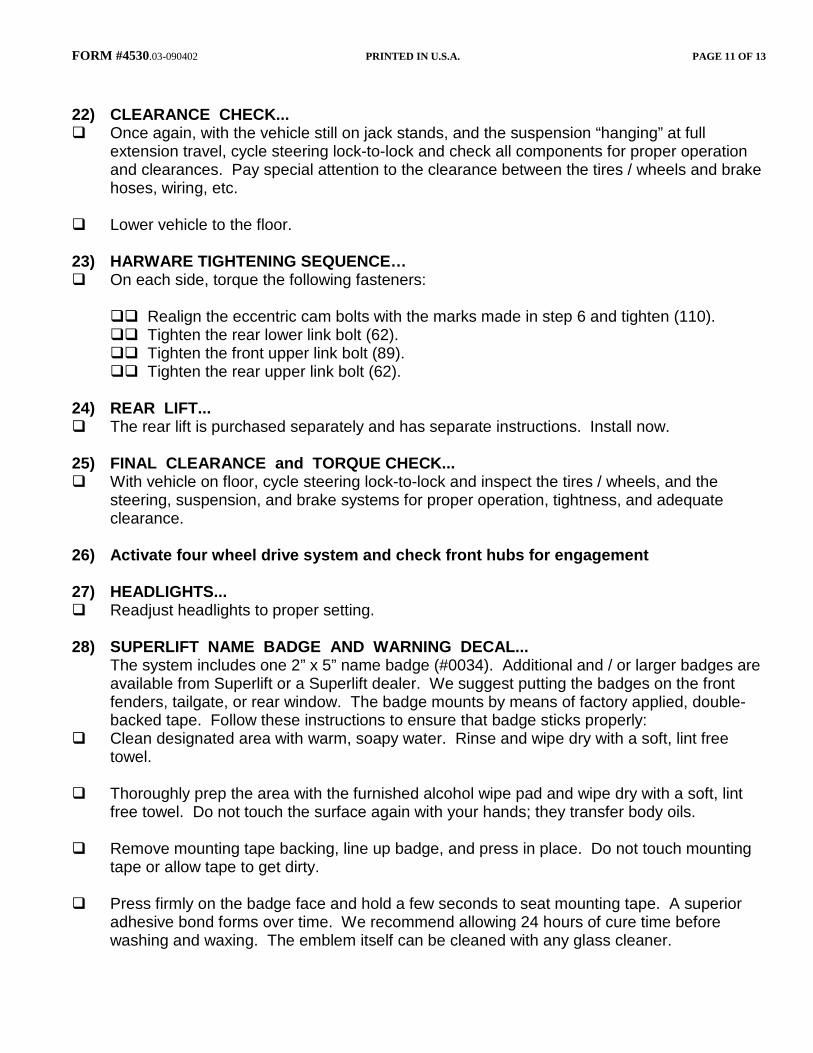
22) CLEARANCE CHECK... Once again, with the vehicle still on jack stands, and the suspension “hanging” at full
extension travel, cycle steering lock-to-lock and check all components for proper operation and clearances. Pay special attention to the clearance between the tires / wheels and brake hoses, wiring, etc.
Lower vehicle to the floor. 23) HARWARE TIGHTENING SEQUENCE… On each side, torque the following fasteners: Realign the eccentric cam bolts with the marks made in step 6 and tighten (110). Tighten the rear lower link bolt (62). Tighten the front upper link bolt (89). Tighten the rear upper link bolt (62). 24) REAR LIFT... The rear lift is purchased separately and has separate instructions. Install now. 25) FINAL CLEARANCE and TORQUE CHECK... With vehicle on floor, cycle steering lock-to-lock and inspect the tires / wheels, and the
steering, suspension, and brake systems for proper operation, tightness, and adequate clearance.
26) Activate four wheel drive system and check front hubs for engagement 27) HEADLIGHTS... Readjust headlights to proper setting. 28) SUPERLIFT NAME BADGE AND WARNING DECAL... The system includes one 2” x 5” name badge (#0034). Additional and / or larger badges are
available from Superlift or a Superlift dealer. We suggest putting the badges on the front fenders, tailgate, or rear window. The badge mounts by means of factory applied, double-backed tape. Follow these instructions to ensure that badge sticks properly:
Clean designated area with warm, soapy water. Rinse and wipe dry with a soft, lint free towel.
Thoroughly prep the area with the furnished alcohol wipe pad and wipe dry with a soft, lint
free towel. Do not touch the surface again with your hands; they transfer body oils. Remove mounting tape backing, line up badge, and press in place. Do not touch mounting
tape or allow tape to get dirty. Press firmly on the badge face and hold a few seconds to seat mounting tape. A superior
adhesive bond forms over time. We recommend allowing 24 hours of cure time before washing and waxing. The emblem itself can be cleaned with any glass cleaner.

FORM #4530.03-090402 PRINTED IN U.S.A. PAGE 12 OF 13
Install the WARNING TO DRIVER decal on the inside of the windshield, or on the dash, within driver’s view. Refer to the “NOTICE TO DEALER AND VEHICLE OWNER” section below.
29) ALIGNMENT... Realign vehicle to factory specifications. IMPORTANT PRODUCT USE INFORMATION As a general rule, the taller a vehicle is, the easier it will roll over. Offset, as much as possible, what is lost in roll over resistance by increasing tire track width. In other words, go “wide” as you go “tall”. Many sportsmen remove their mud tires after winter / hunting season and install ones more appropriate for street driving; always use as wide a tire and wheel combination as possible to enhance vehicle stability. We strongly recommend, because of roll over possibility, that the vehicle be equipped with a functional roll bar and cage system. Seat belts and shoulder harnesses should be worn at all times. Avoid situations where a side rollover may occur. Generally, braking performances and capabilities are decreased when significantly larger / heavier tires and wheels are used. Take this into consideration while driving. Do not add, alter, or fabricate any factory or aftermarket parts to increase vehicle height over the intended height of the Superlift product purchased. Mixing component brands is not recommended. Most states have some type of law limiting vehicle height. The amount of lift allowed, and how the lift may be achieved, varies greatly. Several states offer exemptions for farm or commercially registered vehicles. It is the owner’s responsibility to check state and local laws to ensure that their vehicle will be in compliance. Superlift makes no claims regarding lifting devices and excludes any and all implied claims. Superlift will not be responsible for any altered product or any improper installation or use of our products. We will be happy to answer any questions concerning the design, function, and correct use of our products. IMPORTANT MAINTENANCE INFORMATION It is the ultimate buyer’s responsibility to have all bolts / nuts checked for tightness after the first 100 miles and then every 1000 miles. The steering, suspension and driveline systems, along with wheel alignment should be inspected by a qualified professional mechanic at least every 3000 miles. NOTICE TO DEALER AND VEHICLE OWNER Any vehicle equipped with a Superlift lifting device must have the enclosed “Warning to Driver” decal installed on the inside of the windshield or on the vehicle’s dash, within driver’s view. The “Warning to Driver” decal is to act as a constant safety reminder for whoever may be operating the vehicle. The WARRANTY IS VOID unless this decal is in place. INSTALLING DEALER... It is your responsibility to install warning decal and forward these installation instructions to the vehicle owner for review of warnings, product use and maintenance information. Replacement warning decals are available free upon request. These instructions are to be kept with the vehicle registration papers and owners manual for the service life of the vehicle.

FORM #4530.03-090402 PRINTED IN U.S.A. PAGE 13 OF 13
SUPERLIFT LIMITED LIFETIME WARRANTY Suspension products bearing the Superlift (LKI Ent.) name are warranted for as long as the original purchaser owns the vehicle that the LKI product was originally installed on. This warranty is non-transferable. Warranty covers only the product, no labor, time loss, or freight incurred. Any product that has been abused, altered, incorrectly installed, or used in competition is not covered. Product finish, spring bushings, Polyurethane products, and normal wear is not covered. The LKI product is subject to replacement or repair. No other warranties are expressed or implied. An authorized Superlift dealer must inspect the part in question and confirm that the “Warning to Driver” decal is properly displayed. A copy of the sales invoice is required for warranty consideration.
SUPERLIFT SUSPENSION SYSTEMS 300 Huey Lenard Loop Rd.
West Monroe, Louisiana 71292 Phone: (318) 397-3000
Sales / Tech: 1-800-551-4955 FAX: (318) 397-3040 www.superlift.com