Embed Size (px)
Citation preview

Superresolved phase-shifting Gabor holography by CCD shift
This article has been downloaded from IOPscience. Please scroll down to see the full text article.
2009 J. Opt. A: Pure Appl. Opt. 11 125408
(http://iopscience.iop.org/1464-4258/11/12/125408)
Download details:
IP Address: 147.156.26.39
The article was downloaded on 14/01/2010 at 09:22
Please note that terms and conditions apply.
The Table of Contents and more related content is available
HOME | SEARCH | PACS & MSC | JOURNALS | ABOUT | CONTACT US
IOP PUBLISHING JOURNAL OF OPTICS A: PURE AND APPLIED OPTICS
J. Opt. A: Pure Appl. Opt. 11 (2009) 125408 (6pp) doi:10.1088/1464-4258/11/12/125408
Superresolved phase-shifting Gaborholography by CCD shiftV Mico1, L Granero2, Z Zalevsky3 and J Garcıa1
1 Departamento de Optica, Universitat de Valencia, C/Dr Moliner, 50, 46100 Burjassot, Spain2 AIDO—Technological Institute of Optics, Color and Imaging, C/Nicolas Copernico 7-13,46980 Paterna, Spain3 School of Engineering, Bar-Ilan University, Ramat-Gan, 52900, Israel
E-mail: [email protected]
Received 4 July 2009, accepted for publication 11 August 2009Published 21 September 2009Online at stacks.iop.org/JOptA/11/125408
AbstractHolography in the Gabor regime is restricted to weak diffraction assumptions. Otherwise,diffraction prevents an accurate recovery of the object’s complex wavefront. We have recentlyproposed a modified Gabor-like setup to extend Gabor’s concept to any sample provided that itbe non-diffusive. However, the resolution of the final image becomes limited as a consequenceof the additional elements considered in the proposed setup. In this paper we present anexperimental approach to overcome such a limitation in which the former configuration is usedwhile the CCD camera is shifted to different off-axis positions in order to generate a syntheticaperture. Thus, once the whole image set is recorded and digitally processed for each cameraposition, we merge the resulting band-pass images into one image by assembling a syntheticaperture. Finally, a superresolved image is recovered by Fourier transformation of theinformation contained in the generated synthetic aperture. Experimental results validate ourconcepts for a gain in resolution of close to 2.
Keywords: digital holography, synthetic aperture generation, Fourier image formation, andsuperresolution
(Some figures in this article are in colour only in the electronic version)
1. Introduction
In-line microscopy without lenses (or lensless microscopy) wasoriginally proposed by Gabor as a method to overcome thelimitations introduced by lenses in electron microscopy [1].Basically, Gabor’s concept is based on an in-line architecture,where the sample is illuminated by a coherent beam and arecording device, which is placed behind the sample, recordsthe produced diffracted wavefront which is known as Gabor’shologram. In this configuration, the non-diffracted lightplays the role of a reference beam that interferes with thediffracted components generated by the sample. Thus, itis possible to recover the object’s complex wavefront byusing classical holographic tools in the reconstruction process.However, Gabor’s concept needs to be applied under severesample constraints: the samples must be considered as weakdiffractive. Only in this case, can the sample’s diffractedlight be considered as a perturbation of the reference beam
and Gabor’s underlying principle become true. Otherwise,the amount of light blocked by the object is significant andthe diffraction which dominates the process will prevent thesample’s complex wavefront from being accurately recovered.
The simplest way to remove the Gabor limitation is byreinserting a reference beam at the recording plane. Thus,holography dominates the process independently of the typeof imaged object. Leith and Upatnieks [2–4] reported ondifferent off-line holographic schemes that improve the finalimage reconstruction since they avoid the distortion causedby overlapping, in the observation direction, of the threeholographic terms arising from the in-line architecture.
Nowadays, digital lensless in-line holographic microscopy(the original idea proposed by Gabor merged nowadays withdigital capabilities) combines the development of modernsolid-state image sensors with the numerical processingcapabilities that are provided by computers. This type ofholography has a variety of applications in three-dimensional
1464-4258/09/125408+06$30.00 © 2009 IOP Publishing Ltd Printed in the UK1
J. Opt. A: Pure Appl. Opt. 11 (2009) 125408 V Mico et al
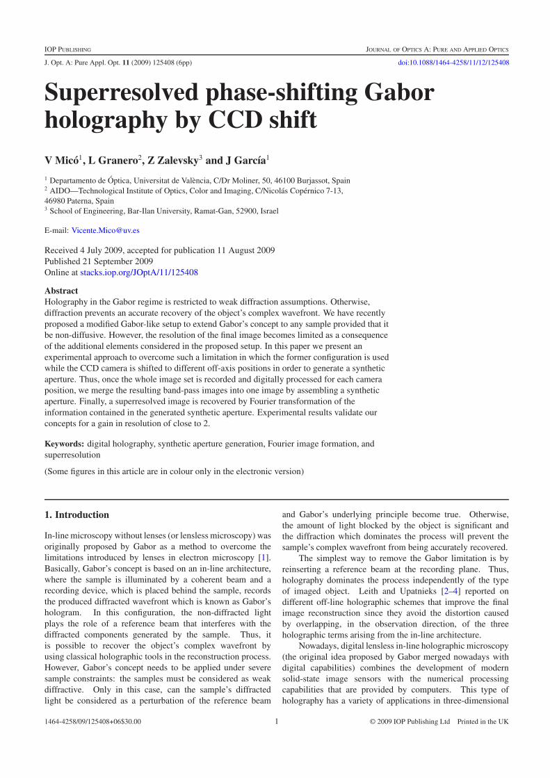
Figure 1. Experimental setup arrangement for the proposed approach: (a) transmissive and (b) reflective configurations.
(3D) imaging with micrometer resolution including underwaterobservations, tracking moving objects and particles, as wellas the study of erosion processes in coastal sediments [5–14].However, all of these approaches suffer from the samelimitation reported in the original idea of Gabor. Once again,and in the same direction pointed out by Leith and Upatnieks,digital in-line holography applying an external reference beamhas also been reported on extensively in the literature [15, 16].Other ingenious approaches are based on digital lenslessFourier holographic architectures where the object and thereference beams are generated from the same plane, followinga common path until reaching the CCD [17, 18].
Recently, Mico et al have validated a new concept inthe field of Gabor’s holography that allows the recovery ofthe complex amplitude of the wavefront incoming from thesample [19]. It is based on a Gabor-like setup, but with theaddition of two new elements. First, a condenser lens, betweenthe input sample and the CCD, which provides focusing ofthe illumination at an intermediate plane (Fourier plane). Andsecond, a spatial light modulator (SLM) which is placed atthe Fourier plane to allow a phase-shifting procedure [20, 21]by modulating its pixels according to the DC term of theobject spectrum. With these modifications, the approachreported in [19] becomes useful for any kind of sample (notonly weakly diffracting objects as in Gabor’s concept), itremoves both zero order and twin image terms from thereconstruction (avoiding distortion and improving the signal-to-noise ratio in the reconstructed images), and eliminates theneed to perform coordinate transformation for high numericalapertures and magnifications (because the complex amplitudedistribution can be precisely propagated). However, due tothe need to locate the Fourier plane between the sample andCCD, the achievable resolution of the method is reduced bydiffraction [22], since it is related to the distance between thesample and the CCD (among other factors).
In this paper, we present a combination of techniquesthat enable one to overcome the resolution limit imposed bydiffraction in the configuration presented in [19]. The basicprinciple is based on shifting the CCD to different off-axispositions in order to synthesize an expanded aperture whichimproves the system’s resolution. Although other authors hadalso implemented synthetic aperture methods by shifting theCCD [23–28], the presented application is novel and provideshighly promising results. Essentially, the way to recover each
frequency band corresponding to each CCD position is thesame one as described in [19]. Since the central part of thesample’s spectrum is responsible for the DC term of the image,that is, for the non-diffracted light in Gabor’s concept, therecorded in-line hologram can be phase shifted in time bymodulating that pixel of the SLM which spatially coincideswith the DC term. By previous calibration of the phase-stepproduced by the SLM, the complex amplitude distribution ofthe diffracted sample wavefront can be recovered by applyingconventional phase-shifting algorithms. This procedure isapplied to each one of the recording positions of the CCDcamera. Following that, the recovered distribution can bepropagated digitally up to the object plane by taking intoaccount a linear phase factor in the back propagation. Such alinear phase factor comes from the CCD displacement. Finally,all the propagated distributions are used to assemble a syntheticexpanded aperture that yields a superresolved image by Fouriertransformation.
Thus, and in summary, the whole proposed procedurecould be understood as a technique based on time multiplexingthe spatial-frequency content diffracted by the input sample ina similar way to that which sequential off-axis illumination per-forms in digital holographic microscopy [29–36], but where thesynthetic aperture is generated by CCD displacement [23–28].The way to recover the complex wavefront diffracted by theobject is by phase-shifting the DC term of the object spec-trum in a similar way to that performed in common-path point-diffraction interferometers [37–41]. This mixing of methodsis first described in section 2 and experimentally validated insection 3.
2. System description and methodology
The experimental setup is depicted in figure 1 andcan be implemented in both transmissive and reflectiveconfigurations. As can be seen, a condenser lens is used tofocus the laser beam onto the SLM and the input object isplaced between the lens and the SLM. In this configuration,the object spectrum is generated at the SLM plane. Finally, aCCD camera records the incoming amplitude distribution. Forthe reflective configuration, a beam splitter is needed to allowthe recording process.
Considering this architecture, it is possible to recoverthe complex amplitude distribution of the wavefront that is
2
J. Opt. A: Pure Appl. Opt. 11 (2009) 125408 V Mico et al
diffracted by the input object [19]. Basically, the techniqueimplies the modulation of the DC term of the image (centralpart of the object spectrum) by phase modulating the pixels ofthe SLM that coincide with the spatial position of the DC term.Thus, after preliminary calibration of the phase-step introducedby the SLM, it is possible to apply a conventional phase-shifting procedure over the intensity images that are providedby the CCD [16]. In the experiments, the SLM provides 64phase levels covering the required full 2π range. Since thepixel size of the SLM is smaller than the central lobe of thespectrum (given by the object extent and its distance to theCCD [41]), an accurate and controllable phase reconstructionis expected. Thus, an in-line hologram is recorded by theCCD and stored in the computer’s memory for each of the64 phases originated at the SLM. After that, a phase-shiftingalgorithm is applied to the whole set of 64 stored intensitiesto perform the recovery of the complex wavefront that isdiffracted by the input object. And finally, the resultingamplitude distribution is digitally back propagated to the objectplane using the convolution method applied to the diffractionRayleigh–Sommerfeld integral [17, 19]. This method can beapplied provided that there is a DC term in the object spectrumand without the need for the weak diffraction assumption (asrequired for conventional Gabor holograms).
Now, we will focus on the way to improve the resolutionof the method reported in [19]. Since the method needs toprovide the object spectrum in a plane between the input objectand the CCD camera, there is a minimum distance at which tolocate the CCD after the input object. Given the CCD sensorsize, such a distance is related to the numerical aperture (NA)of the condenser lens in the transmissive configuration, andwith the condenser lens NA and the size of the beam splitterin the reflective configuration. Let us call this distance d .This fact means that the resolution of the proposed imagingsystem will be limited according to the relation Ri = λ/NAi ,where R is the resolution of the imaging system, λ is theillumination wavelength, NA is the numerical aperture definedby the CCD size at distance d from the input object, and thesub-index i designates the horizontal and vertical directions(given that the CCD is rectangular). So, different resolutionlimits, that depend on the selected observation direction, areobtained.
To overcome this resolution limit, we propose shifting theCCD in order to generate a synthetic aperture. Since the objectthat was selected to validate the proposed method is composedof horizontal and vertical lines, we shift the CCD to 4 off-axis positions (2 horizontally and 2 vertically), but any othersynthetic aperture could be synthesized if it is required. Theonly restriction to apply in the proposed method is that theNA of the condenser lens should be high enough to ensurenon-diffracted light (reference beam) at the positions where theCCD is displaced. This situation is depicted in figure 1. Thus,the synthetic numerical aperture (SNA) can be expanded untilreaching at least the NA of the condenser lens. However, sincethe CCD is a few millimeters in size, the NA of the condenserlens is not a restrictive factor.
Once the phase-shifting procedure is applied for a givenCCD off-axis recording position, we perform back propagation
up to the input plane, by taking into account a linear phasefactor in the propagation, to allow the overlapping of thesame portion of the object field of view. This linear phaseis responsible for a prismatic effect in the propagation andit can be calculated, first by visual criterion, and then a fineadjustment is obtained by maximizing the correlation peakbetween the on-axis recovered image and the off-axis oneswhen considering different linear phases. Thus, we ensure therecovery of a different spectral content of the same input objectfield of view.
Finally, a synthetic aperture is assembled by placing thespatial-frequency content of the recovered band-pass imagesto its original position in the object spectrum. However, a fineadjustment of the phase of each band-pass image is needed,since each recording position will have different recordingphase conditions due mainly to two reasons. First, we mustconsider the addition of a global phase to each recoveredband-pass image. This global phase is due to subwavelengthdistance mismatches in the optical path that are impossibleto match on each recording separately. And second, we findthe replacement of each recovered rectangular aperture to itsoriginal position in the object spectrum. This procedure isachieved in two steps. By knowing the displacement of theCCD in comparison to the CCD size, it is possible to adda linear phase factor to the recovered band-pass image inorder to shift each elementary aperture to its rough positionin the Fourier domain. Later, a final and fine adjustment isachieved by the addition of smaller linear phase factors inboth horizontal and vertical directions. In addition, this finetuning process compensates for phase variations coming frommisalignments in the optical setup. This procedure is repeatedfor every elementary rectangular aperture considered in theexperiment. The full adjustment can be guided by an imagequality criterion and automated to yield a superresolved imageby simple inverse Fourier transformation of the informationcontained in the generated synthetic aperture.
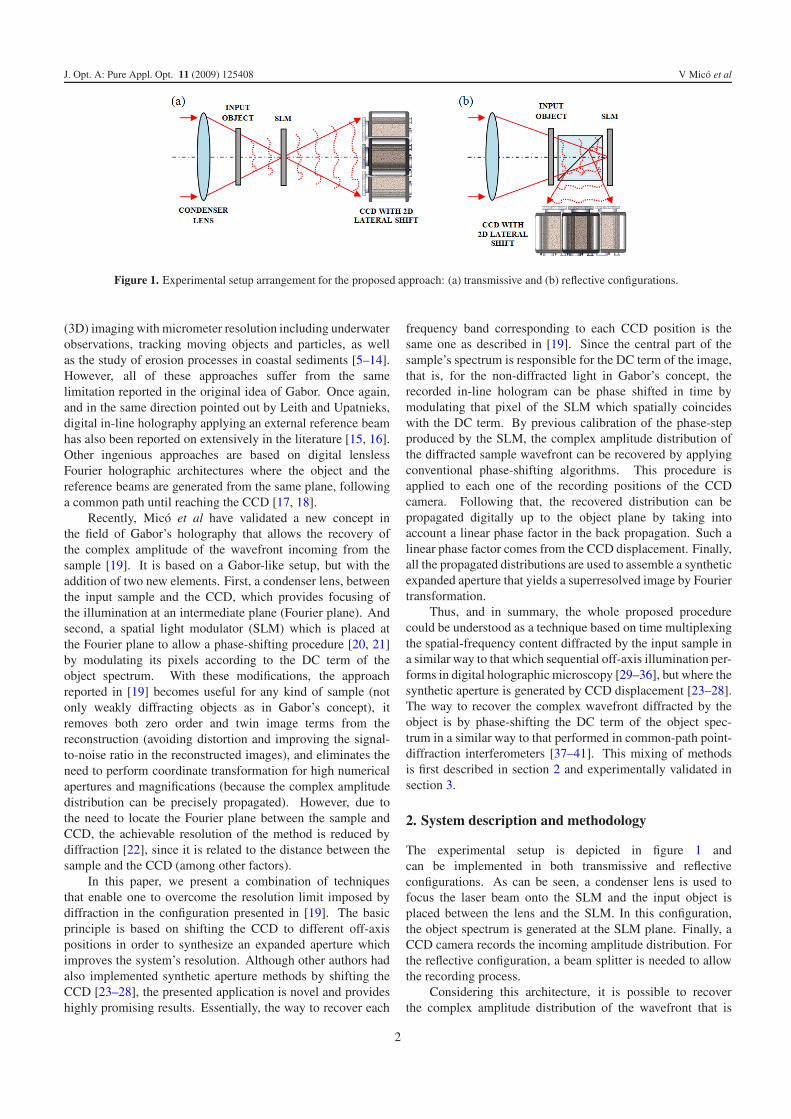
3. Experimental validation
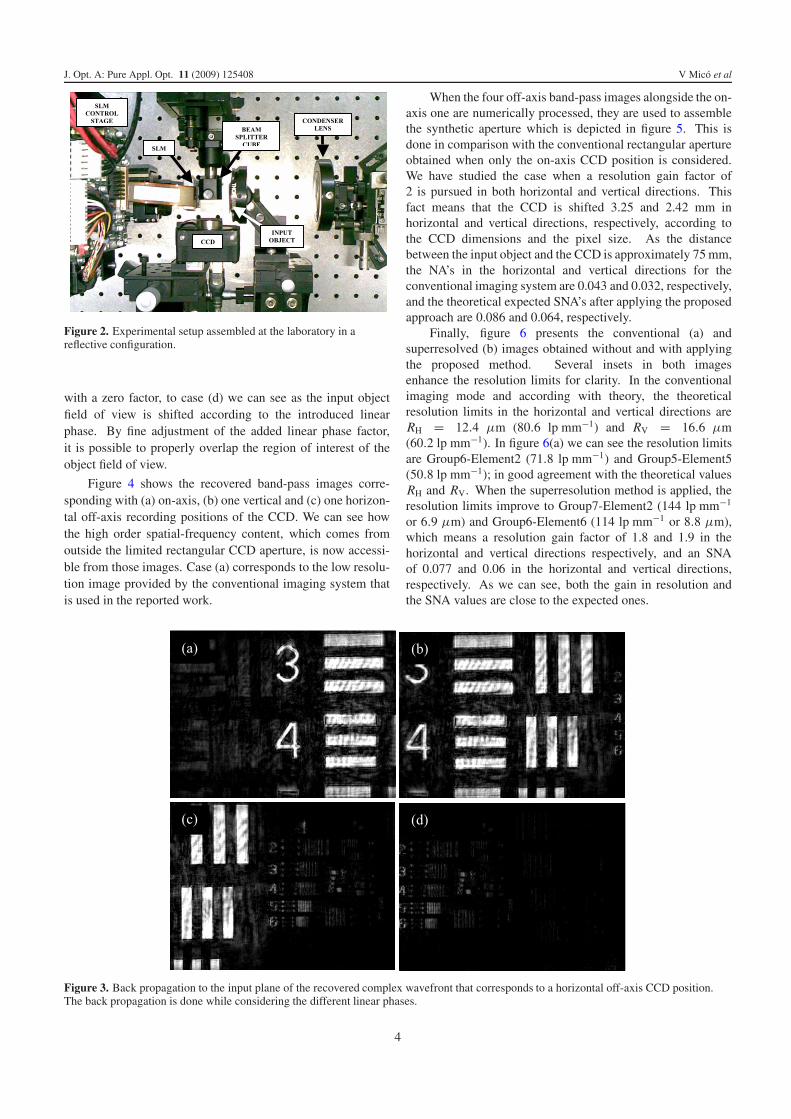
The reflective configuration that is depicted in figure 1was selected for the experimental implementation, and it ispresented in figure 2. A doublet lens (80 mm focal lengthand 60 mm diameter) is used as a condenser lens to focusthe laser beam (532 nm wavelength) onto a reflective SLM(Holoeye HEO 1080 P, 1920 pixel × 1080 pixel resolution,8 μm pixel pitch). The SLM is controlled by a computer thatallows the gray levels to be changed for the relevant pixels ofSLM that coincide with the DC term of the object spectrum.A negative USAF resolution test target is used as an inputobject to demonstrate the resolution improvement. Finally, abeam splitter cube (20 mm × 20 mm size) is used to reflectthe light onto a CCD camera (Basler A312f, 582 pixels ×782 pixels, 8.3 μm pixel size, 12 bits/pixel). Optical mountsand micrometric translation stages complete the experimentalsetup.
As an example of back propagation with different linearphase factors, figure 3 shows the case when the CCD is shiftedto a left (horizontal) position. From case (a), corresponding
3
J. Opt. A: Pure Appl. Opt. 11 (2009) 125408 V Mico et al
Figure 2. Experimental setup assembled at the laboratory in areflective configuration.
with a zero factor, to case (d) we can see as the input objectfield of view is shifted according to the introduced linearphase. By fine adjustment of the added linear phase factor,it is possible to properly overlap the region of interest of theobject field of view.
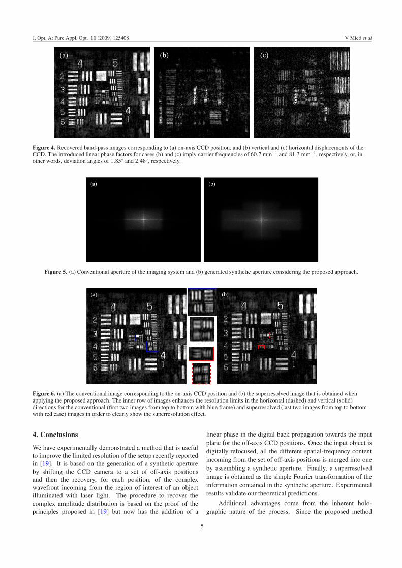
Figure 4 shows the recovered band-pass images corre-sponding with (a) on-axis, (b) one vertical and (c) one horizon-tal off-axis recording positions of the CCD. We can see howthe high order spatial-frequency content, which comes fromoutside the limited rectangular CCD aperture, is now accessi-ble from those images. Case (a) corresponds to the low resolu-tion image provided by the conventional imaging system thatis used in the reported work.
When the four off-axis band-pass images alongside the on-axis one are numerically processed, they are used to assemblethe synthetic aperture which is depicted in figure 5. This isdone in comparison with the conventional rectangular apertureobtained when only the on-axis CCD position is considered.We have studied the case when a resolution gain factor of2 is pursued in both horizontal and vertical directions. Thisfact means that the CCD is shifted 3.25 and 2.42 mm inhorizontal and vertical directions, respectively, according tothe CCD dimensions and the pixel size. As the distancebetween the input object and the CCD is approximately 75 mm,the NA’s in the horizontal and vertical directions for theconventional imaging system are 0.043 and 0.032, respectively,and the theoretical expected SNA’s after applying the proposedapproach are 0.086 and 0.064, respectively.
Finally, figure 6 presents the conventional (a) andsuperresolved (b) images obtained without and with applyingthe proposed method. Several insets in both imagesenhance the resolution limits for clarity. In the conventionalimaging mode and according with theory, the theoreticalresolution limits in the horizontal and vertical directions areRH = 12.4 μm (80.6 lp mm−1) and RV = 16.6 μm(60.2 lp mm−1). In figure 6(a) we can see the resolution limitsare Group6-Element2 (71.8 lp mm−1) and Group5-Element5(50.8 lp mm−1); in good agreement with the theoretical valuesRH and RV. When the superresolution method is applied, theresolution limits improve to Group7-Element2 (144 lp mm−1
or 6.9 μm) and Group6-Element6 (114 lp mm−1 or 8.8 μm),which means a resolution gain factor of 1.8 and 1.9 in thehorizontal and vertical directions respectively, and an SNAof 0.077 and 0.06 in the horizontal and vertical directions,respectively. As we can see, both the gain in resolution andthe SNA values are close to the expected ones.
Figure 3. Back propagation to the input plane of the recovered complex wavefront that corresponds to a horizontal off-axis CCD position.The back propagation is done while considering the different linear phases.
4
J. Opt. A: Pure Appl. Opt. 11 (2009) 125408 V Mico et al
Figure 4. Recovered band-pass images corresponding to (a) on-axis CCD position, and (b) vertical and (c) horizontal displacements of theCCD. The introduced linear phase factors for cases (b) and (c) imply carrier frequencies of 60.7 mm−1 and 81.3 mm−1, respectively, or, inother words, deviation angles of 1.85◦ and 2.48◦, respectively.
Figure 5. (a) Conventional aperture of the imaging system and (b) generated synthetic aperture considering the proposed approach.
Figure 6. (a) The conventional image corresponding to the on-axis CCD position and (b) the superresolved image that is obtained whenapplying the proposed approach. The inner row of images enhances the resolution limits in the horizontal (dashed) and vertical (solid)directions for the conventional (first two images from top to bottom with blue frame) and superresolved (last two images from top to bottomwith red case) images in order to clearly show the superresolution effect.
4. Conclusions
We have experimentally demonstrated a method that is usefulto improve the limited resolution of the setup recently reportedin [19]. It is based on the generation of a synthetic apertureby shifting the CCD camera to a set of off-axis positionsand then the recovery, for each position, of the complexwavefront incoming from the region of interest of an objectilluminated with laser light. The procedure to recover thecomplex amplitude distribution is based on the proof of theprinciples proposed in [19] but now has the addition of a
linear phase in the digital back propagation towards the inputplane for the off-axis CCD positions. Once the input object isdigitally refocused, all the different spatial-frequency contentincoming from the set of off-axis positions is merged into oneby assembling a synthetic aperture. Finally, a superresolvedimage is obtained as the simple Fourier transformation of theinformation contained in the synthetic aperture. Experimentalresults validate our theoretical predictions.
Additional advantages come from the inherent holo-graphic nature of the process. Since the proposed method
5
J. Opt. A: Pure Appl. Opt. 11 (2009) 125408 V Mico et al
recovers both the amplitude and phase information that isdiffracted by the object, quantitative superresolved phase in-formation (in a way that is similar to the approach discussedin [35]), and superresolved imaging for 3D samples (in a waythat is similar to [36]) are also possible.
Acknowledgment
This work has been partially supported by the SpanishMinisterio de Educacion y Ciencia under the project FIS2007-60626.
References
[1] Gabor D 1948 A new microscopic principle Nature 161 777–8[2] Leith E N and Upatnieks J 1962 Reconstructed wavefronts and
communication theory J. Opt. Soc. Am. 52 1123–30[3] Leith E N and Upatnieks J 1963 Wavefront reconstruction with
continous-tone objects J. Opt. Soc. Am. 53 1377–81[4] Leith E N and Upatnieks J 1964 Wavefront reconstruction with
diffuse illumination and three-dimensional objects J. Opt.Soc. Am. 54 1295–301
[5] Xu W, Jericho M H, Meinertzhagen I A and Kreuzer H J 2001Digital in-line holography for biological applications Proc.Natl Acad. Sci. USA 98 11301–5
[6] Watson J et al 2001 Simultaneous in-line and off-axis subseaholographic recording of plankton and other marine particlesMeas. Sci. Technol. 12 L9–15
[7] Hobson P R and Watson J 2002 The principles and practice ofholographic recording of plankton J. Opt. A: Pure Appl. Opt.4 S34–49
[8] Pedrini G and Tiziani H J 2002 Short-coherence digitalmicroscopy by use of a lensless holographic imaging systemAppl. Opt. 41 4489–96
[9] Xu W, Jericho M H, Meinertzhagen I A and Kreuzer H J 2003Tracking particles in 4D with in-line holographicmicroscopy Opt. Lett. 28 164–6
[10] Sun H, Perkins R G, Watson J, Player M A and Paterson D M2004 Observations of coastal sediment erosion using in-lineholography J. Opt. A: Pure Appl. Opt. 6 703–10
[11] Malkiel E, Abras J N and Katz J 2004 Automated scanning andmeasurements of particle distributions within a holographicreconstructed volume Meas. Sci. Technol. 15 601–12
[12] Repetto L, Piano E and Pontiggia C 2004 Lensless digitalholographic microscope with light-emitting diodeillumination Opt. Lett. 29 1132–4
[13] Garcia-Sucerquia J, Xu W, Jericho S K, Klages P,Jericho M H and Kreuzer H J 2006 Digital in-lineholographic microscopy Appl. Opt. 45 836–50
[14] Garcia-Sucerquia J, Xu W, Jericho M H and Kreuzer H J 2006Immersion digital in-line holographic microscopy Opt. Lett.31 1211–3
[15] Schnars U and Jueptner W P 2005 Digital Holography (Berlin:Springer)
[16] Kreis T 2005 Handbook of Holographic Interferometry:Optical and Digital Methods (Weinheim: Wiley–VCHVerlag GmbH & Co. KGaA)
[17] Haddad W S, Cullen D, Solem J C, Longworth J W,McPherson A, Boyer K and Rhodes Ch K 1992Fourier-transform holographic microscope Appl. Opt.31 4973–8
[18] Takaki Y and Ohzu H 1999 Fast numerical reconstructiontechnique for high-resolution hybrid holographicmicroscopy Appl. Opt. 38 2204–11
[19] Mico V, Garcıa J, Zalevsky Z and Javidi B 2009 Phase-shiftingGabor holography Opt. Lett. 34 1492–4
[20] Yamaguchi I and Zhang T 1997 Phase-shifting digitalholography Opt. Lett. 22 1268–70
[21] Yamaguchi I, Kato J, Ohta S and Mizuno J 2001 Imageformation in phase-shifting digital holography andapplications to microscopy Appl. Opt. 40 6177–85
[22] Abbe E 1873 Beitrage zur theorie des mikroskops und dermikroskopischen wahrnehmung Arch. Mikrosk. Anat.9 413–68
[23] Le Clerc F, Gross M and Collot L 2001 Synthetic apertureexperiment in the visible with on-axis digital heterodyneholography Opt. Lett. 26 1550–2
[24] Massig J H 2002 Digital off-axis holography with a syntheticaperture Opt. Lett. 27 2179–81
[25] Binet R, Colineau J and Lehureau J-C 2002 Short-rangesynthetic aperture imaging at 633 nm by digital holographyAppl. Opt. 41 4775–82
[26] Kreiss T and Schluter K 2007 Resolution enhancement byaperture synthesis in digital holography Opt. Eng.46 055803
[27] Di J, Zhao J, Jiang H, Zhang P, Fan Q and Sun W 2008 Highresolution digital holographic microscopy with a wide fieldof view based on a synthetic aperture technique and use oflinear CCD scanning Appl. Opt. 47 5654–8
[28] Martınez-Leon L and Javidi B 2008 Synthetic aperturesingle-exposure on-axis digital holography Opt. Express16 161–9
[29] Schwarz Ch J, Kuznetsova Y and Brueck S R 2003 Imaginginterferometric microscopy Opt. Lett. 28 1424–6
[30] Mico V, Zalevsky Z, Garcıa-Martınez P and Garcıa J 2006Superresolved imaging in digital holography bysuperposition of tilted wavefronts Appl. Opt. 45 822–8
[31] Mico V, Zalevsky Z and Garcıa J 2006 Superresolution opticalsystem by common-path interferometry Opt. Express14 5168–77
[32] Indebetouw G, Tada Y, Rosen J and Brooker G 2007 Scanningholographic microscopy with resolution exceeding theRayleigh limit of the objective by superposition of off-axisholograms Appl. Opt. 46 993–1000
[33] Kuznetsova Y, Neumann A and Brueck S R J 2007 Imaginginterferometric microscopy—approaching the linear systemlimits of optical resolution Opt. Express 15 6651–63
[34] Price J R, Bingham P R and Thomas C E Jr 2007 Improvingresolution in microscopic holography by computationallyfusing multiple, oblique illuminated object waves in theFourier domain Appl. Opt. 46 827–33
[35] Mico V, Zalevsky Z and Garcıa J 2008 Common-pathphase-shifting digital holographic microscopy: a way toquantitative imaging and superresolution Opt. Commun.281 4273–81
[36] Mico V, Zalevsky Z, Ferreira C and Garcıa J 2008Superresolution digital holographic microscopy forthree-dimensional samples Opt. Express 16 19260–70
[37] Kadono H, Takai N and Asakura T 1987 New common-pathphase-shifting interferometer using a polarization techniqueAppl. Opt. 26 898–904
[38] Mercer C R and Creath K 1994 Liquid-crystal point-diffractioninterferometer Opt. Lett. 19 916–8
[39] Medecki H, Tejnil E, Goldberg K A and Bokor J 1996Phase-shifting point diffraction interferometer Opt. Lett.21 1526–8
[40] Iemmi C, Moreno A and Campos J 2005 Digital holographywith a point diffraction interferometer Opt. Express13 1885–91
[41] Neal R M and Wyant J C 2006 Polarization phase-shiftingpoint-diffraction interferometer Appl. Opt. 45 3463–76
6